1
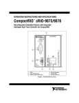
Gas Continuous Flow Hot Water System
Installation Manual
Congratulations
Contents
Congratulations and thank you for choosing our gas
continuous flow hot water system. We are sure you will find
your new hot water system a pleasure to use. Before you
install the hot water system, we recommend that you read
through the entire installation manual, which provides the
description of the hot water system, its functions and how to
install it correctly. To avoid the risks that are always present
when you use an appliance, it is important that the hot water
system is installed correctly and that you read the safety
instructions carefully to avoid misuse and hazards.
Important........................................................................... 3
After unpacking the hot water system please check it is not
damaged. If in doubt, do not use the hot water system but
contact your local Electrolux Customer Care Centre using the
number located at the back of this installation guide.
NOTE: The actual gas heating appliance that is part of this
gas continuous flow hot water system will here after be
refered to as "water heater" for the purposes of this manual.
The gas continuous flow hot water system as a whole may
also be refered to as "hot water system" for simplicity.
environmental tips
Information on disposal for users
• Most of the packing materials are recyclable.
Please dispose of those materials through your local
recycling depot or by placing them in appropriate
collection containers.
• If you wish to discard this gas continuous hot water
system, please contact your local authorities and ask for
the correct method of disposal.
caution
• The hot water system is not intended for use by young
children or infirm persons without supervision.
• Children should be supervised to ensure that they do not play with the hot water system.
• Contact an authorised installer for installation of this hot
water system.
• Contact an authorised service technician for repair or
maintenance of this hot water system.
• If the power cord is to be replaced, replacement work
must be performed by authorised personnel only.
• Installation work must be performed in accordance
with national standards by authorised personnel only.
Wrong connection can cause over heating or fire.
•This hot water system should be installed in accordance
with AS/NZS 3000 and your electricity suppliers rules.
• The installation of this hot water system must comply
with the standards set in AS/NZS 3500.4 - Hot Water
Supply Systems.
Conditions of use
This hot water system is intended to be used in household
and similar applications such as :
• staff kitchen areas in shops, offices and other working environments.
• farm houses.
• by clients in hotels, motels and other residential type environments.
• bed and breakfast type environments
2 contents Kelvinator Gas Continuous Flow hot water system
Important safety instructions............................................ 4
For the plumber................................................................. 5
Dimensions and connection points.................................... 6
Installation.......................................................................... 8
Clearances.......................................................................... 9
Gas connection................................................................. 10
Water connection............................................................. 11
Electrical connection........................................................ 12
Remote controller........................................................... 13
Remote controller Installation......................................... 14
Commissioning Instructions............................................. 16
Troubleshooting............................................................... 18
PCB error codes............................................................... 19
Warranty........................................................................... 23
Important
This Installation Manual has been prepared for the installers
of the gas continuous flow hot water system.
This symbol indicates never to do this
Meanings of symbols used in this manual are shown below:
warning
This symbol indicates information concerning your
personal safety
This symbol indicates always do this
warning
caution
This symbol indicates information on how to avoid
damaging the gas continuous flow hot water system.
tips & information
This symbol indicates tips and information about
use of the gas continuous flow hot water system.
environmental tips
This symbol indicates tips and information about
economical and ecological use of the gas continuous flow
hot water system.
For the installer
The installation must be completed in accordance with the
information supplied in this Installation Manual.
All other relevant National, State or Local regulations must
also be conformed with and these include (but are not
limited to):
•
Australian Standard AS3500.1 – Water Supply
•
Australian Standard AS3500.4 – Hot Water Supply
•
Australian Standard AS3000 – Electrical Installation
•
Australian Gas Association Code AS5601 –
Gas Appliance Installation
•
Local Water, Gas & Electrical Authority Regulations
Municipal Building Codes
Connect with power properly.
Otherwise, it may cause electric shock or fire due to
excess heat generation.
Always ensure effective earthing.
No earthing may cause electric shock.
Disconnect the power and turn off the gas inlet
valve to the water heater if strange sounds, smell, or
smoke comes from it.
It may cause fire and electric shock.
Do not operate or stop the water heater by switching
on or off the power.
It may cause electric shock or fire due to heat generation.
Do not damage or use an unspecified power cord.
It may cause electric shock or fire.
If the power cord is damaged, it must be replaced by
the manufacturer or an authorised service centre or a
similarly qualified person in order to avoid a hazard.
Do not modify power cord length or share the outlet
with other appliances.
It may cause electric shock or fire due to heat generation.
Do not operate with wet hands or in damp environment.
It may cause electric shock.
Do not allow water to run into electric parts.
It may cause failure of machine or electric shock.
Do not use the socket if it is loose or damaged.
It may cause fire and electric shock.
Do not open the water heater during operation.
It may cause electric shock.
warning
Installation must be performed by a qualified installer (for
example, a licensed plumber or gas fitter).
Do not allow the power cord to rest close to hot
surfaces.
It may cause fire and electric shock.
Do not disassemble or modify the water heater.
It may cause failure and electric shock.
warning
This gas continuous flow hot water system is not intended
for use by persons (including children) with reduced
physical, sensory or mental capabilities, or lack of
experience or knowledge, unless they have been given
supervision or instruction concerning use by a person
responsible for their safety. Children should be supervised
to ensure that they do not play with the gas continuous flow
hot water system.
Kelvinator Gas Continuous Flow hot water system important notes 3
Important safety instructions
Ensure the following safety instructions are read and
understood before commencing installation.
warning
For the continued safety of this appliance it must be
installed, operated and maintained in accordance with the
manufacturer's instructions.
warning
Vapours from flammable liquids will explode and catch fire
causing death or severe burns.
Do not use or store flammable products such as gasoline,
solvents or adhesives near the water heater.
Keep flammable products:
warning
If you do not follow these instructions exactly, a fire or
explosion may result causing property damage, personal
injury or loss of life.
1. Far away from the water heater
2. In approved containers
3. Tightly closed
4. Out of children's reach
Vapours:
1. The gas continuous flow hot water system does not have
a pilot. It is equipped with an internal ignition device that
automatically lights the burner. Do not try and light the
burner by hand.
2. BEFORE OPERATING use a suitable gas detector to
check all around the hot water system for evidence of
leaking gas. Be sure to check close to the ground if you
are using LP gas as it is heavier than air and may settle on
the ground.
1. Cannot be seen
2. Vapours are heavier than air
3. Go a long way on the floor
4. Can be carried from other rooms to the main burner by
air currents
WHAT TO DO IF YOU SMELL GAS.
• Do not try to light the water heater.
• Do not touch any electrical switch
• Do not use any phone in your building
• Check and isolate the main gas valve
• Immediately call your gas supplier from a neighbour's
phone. Follow the gas supplier's instructions
• If you cannot reach your gas supplier, call the fire
department
3. When turning the gas valve knob, do so only by hand,
never use tools. If you can not do this, do not try and
repair it.
4. Do not use the water heater if any part has been under
water. Immediately call a qualified service technician
to inspect the water heater and to replace any
damaged parts.
4 important safety instructions Kelvinator Gas Continuous Flow hot water system
FLAMMABLES
FLAMMABLE VAPOURS
For the plumber
PLEASE NOTE this water heater is supplied factory set to
comply with the requirements of AS 3498.
If you are installing a 60°C or 70°C gas continuous flow hot
water system, a tempering valve is to be installed for the
hot water supplying sanitary fixtures primarily used for the
purpose of personal hygiene.
Please follow all the installation instructions in this manual
including the following instructions regarding the water
heater outlet connection:
• For information relating to burner test point pressures
and injector sizes refer to the rating plate located on the
right hand side of the cabinet for each model (please
refer to the diagram at the bottom of this page showing
the locations of the labels on the water heater).
• For information relating to overall dimensions and
connection points refer to diagrams on pages 6 & 7.
• Before installing in areas over 1500 m above sea level,
contact the manufacturer for instructions.
1. When connecting the hot water supply to the fixtures in
the property, a minimum of three (3) metres of pipework
must be used between the outlet of the water heater and
the first tap or outlet. If you are installing a 60°C or 70°C
model, only a minimum of one (1) meter of pipework is
necessary. See diagram to the right.
2. The hot water outlet line from the water heater should be
covered with 20mm pipe insulation or similar to prevent
heat loss and persons coming in contact with it.
3. When the installation is completed, the temperature of
the hot water supplying sanitary fixtures primarily used
for the purpose of personal hygiene, for example the
bathroom shower/taps, shall be checked to ensure it does
not exceed 50°C. If a 50°C model gas continuous flow hot
water system has been installed, all hot water taps and
fixtures need to be checked to ensure they do not
exceed 50°C.
KGC20BNA
KGC20KNA
KGC20SNA
KGC20BLA
KGC20KLA
KGC20SLA
KGC26BNA
KGC26KNA
KGC26SNA
KGC26BLA
KGC26KLA
KGC26SLA
Capacity L/min
20L/min
26L/min
Gas Input MJ/h
160
195
1.13 min.
1.13 min.
kPa – Nat. Gas
2.75 max.
2.75 max.
Supply Inlet Pressure
kPa - LPG
2.61 min
2.61 min
2.89 max
2.89 max
Water Supply
150* min
150* min.
Pressure kPa
1200 max
1200 max
Height mm
542
542
Depth mm
170
215
Width mm
350
350
MODELS
Supply
Inlet Pressure
Weight kg
15.7
17.2
Gas Connection mm
20 BSP
20 BSP
Water Connections
15 BSP
15 BSP
Electronic
Electronic
240 AC
240 AC
0.8A
0.8A
Ignition
Electrical Supply Voltage
Operating current
*The water heater will operate at reduced performance if inlet water supply
pressure is below 340 kPa.
Note: If the gas supply pressure exceeds the maximum
value in the above table for the respective gas type, fit an
appropriate pressure limiting valve at the inlet to the gas inlet
of the water heater.
• Total length to first tap or outlet is required to be a
minimum of 3 metres from the outlet connection of
the water heater (minimum 1 metre for 60°C and 70°C
models).
• Pipe size is nominal 1/2" from hot water outlet to the first
tap or outlet.
Accessories
4 tapping screws are included with the water heater.
Serial number
label position
Rating label
position
Gas type label
position
Kelvinator Gas Continuous Flow hot water system for the plumber 5
Exterior view –
KGC20BNA/KGC20BLA
KGC20KNA/KGC20KLA
KGC20SNA/KGC20SLA
top fixing positions
top fixing positions
350mm
170mm
330mm
94mm
60mm
37mm
19mm
31mm power
41mm hot
49mm cold
490mm
542mm
198mm
hot
46mm:cold
cold
79mm
power
34mm
133mm
86mm:gas
gas
124mm
114mm:hot
124mm:power
bottom fixing positions
bottom fixing positions
gas
hot
108mm
98mm
70mm
30mm
cold
335mm
6 dimensions KGC20BNA/KGC20BLA, KGC20KNA/KGC20KLA, KGC20SNA/KGC20SLA Kelvinator Gas Continuous Flow hot water system
47mm gas
15.7mm
520mm
137mm
Exterior view –
KGC26BNA/KGC26BLA
KGC26KNA/KGC26KLA
KGC26SNA/KGC26SLA
top fixing positions
215mm
182mm
top fixing positions
350mm
330mm
94mm
60mm
15.7mm
19mm
37mm
44.5mm gas
25mm power
41mm hot
49mm cold
490mm
520mm
542mm
198mm
hot
cold power
84mm 34mm
133mm gas – 124mm
61mm:cold
125mm:gas
154mm:hot
169mm:power
bottom fixing positions
bottom fixing positions
hot
gas
138mm
153mm
cold
109mm
45mm
335mm
Kelvinator Gas Continuous Flow hot water system dimensions – KGC26BNA/KGC26BLA, KGC26BLA/KGC26KLA, KGC26SNA/KGC26SLA 7
Installation
The water heater requires careful and correct installation
to ensure safe and efficient operation. This manual must be
followed exactly. Read the SAFETY GUIDELINES and the
IMPORTANT sections at the beginning of this manual.
Confirm the water heater suitability
Check the gas type label and the rating plate for the correct
gas type, gas pressure, water pressure and electrical rating
for your application. Do not install this water heater if these
requirements can’t be met.
If this water heater is to be installed in a recess box, please
refer to the installation manual supplied with the recess box
for specific instructions regarding this type of installation.
caution
• The water heater must be installed outdoors only. Do not
install the water heater indoors.
• This equipment is not suitable for pool or spa heating.
• Water hardness may affect the water heater. It may be
damaged. It is important that the water heater is installed
in water conditions that are suitable for its efficient,
long term use.
• This is a water heating apparatus only and the final fitness
of water delivered is dependent upon the quality of water
supplied to this system.
• The connection, attachment, integration or general
association of other equipment or parts not specified by
the water heater which either directly or indirectly affect
the operation or performance of this equipment – could
void the warranty.
• Before making connections to the water heater, remove
any transit protection designed to prevent dirt and debris
from entering the water heater.
• The manifold pressure is preset at the factory. It is
computer controlled and does not need adjustment.
• Occupants are to be advised of any inconveniences which
could occur such as disconnection of services.
• Please follow the electrical earthing procedure outlined in
AS3500.4 before cutting or uncoupling existing metallic
pipework.
• To ensure the optimal performance of the water heater, it
should be installed as close as practical to the most used
hot water fixtures and have 20mm insulation covering the
hot water piping. This will minimise heat loss, water usage
and cost to the customer. Keep in mind though that a
minimum distance of three metres is required between the
outlet of the water heater and the first fixture (minimum
one metre for 60°C and 70°C models).
• The water heater requires a fireproof back plate if installed
on timber wall.
Selecting an installation location
Carefully read this section before selecting the installation
location and installing the water heater. The installer must
follow these precautions exactly.
8 installation Kelvinator Gas Continuous Flow hot water system
caution
• Although the water heater is designed to operate with
minimal noise, it is recommended that you do not install
the water heater adjacent to bedrooms or other areas
designed to be quiet.
• Locate your water heater close to a drain where leakage
will not damage surrounding areas. As with any water
heating appliance, the potential for leakage at some time
during the life of the product does exist.
• The water heater shall be installed far away from any
flammable or combustible materials including wood and
cardboard. It must also have adequate ventilation to allow
the proper combustion of the gas inside the heater to
take place.
warning
• Ensure every care is taken to warn occupants of the
building and the public of any injury that may occur from
falling tools, open trenches, water connections or any
other general hazard.
• Make sure the water heater will have enough
combustion air and proper ventilation.
• Keep the area around the water heater clean. Particles
may clog the air vent, reduce fan function, or cause
improper combustion.
• Locate the water heater to allow for easy access for
service and maintenance. Install the water heater so that
it can be connected or removed easily.
• Do not locate your water heater in a pit or any location
where gas and water can accumulate.
• Check the proximity of gas and electrical lines so as not
to create a hazard and avoid access problems for other
services.
• It must be located in accordance with the requirements
of AS5601 and have sufficient clearances from eaves,
windows, vents etc. – see the diagram on p.9.
• Exemption from Prescribed Statutory Requirement:
AS5601-2000 Clause 5.13.6.5, This relates to the physical
separation distance specification where multiple
appliances are employed. That equates to a minimum
150mm horizontal flue separation distance allowing
appliances to be placed side by side in the same
vertical plane
• Most load bearing walls such as brick, brick/veneer,
weatherboard and stud-frames are suitable locations.
• Securely fasten the water heater to the wall with a fixing
solution suitable to the type of material the wall is made
from. A minimum of two screws or bolts at the top and
two screws or bolts at the bottom must be used.
Note: Refer to pages 6 & 7 for fixing positions.
Clearances for outdoor heater locations –
AS5601
This diagram and reference table has been taken from the AS/NZS 5601 standard regarding gas installations. Any references on this page to
clauses or appendix figures are referring directly to this standard.
j
T
j
openable
window
j
h
a
e
h
n
f
e
P
h
c
see note 3
d
g
k
c
T
g
k
d
b
T
see note 2
T – Flue terminal
I – Mechanical air inlet
Reference
a
b
c
d
e
f
g
h
j
k
n
M – Gas meter
P – Electricity meter
or fuse box
Shading indicates prohibited
areas for flue terminals
Item
Below eaves, balconies and other projections:
• appliances up to 50MJ/h input
• appliances over 50MJ/h input
From the ground above a balcony surface*
From a return wall or external corner*
From a gas meter (M) (see 4.7.11 for vent terminal location
of regulator)
From an electricity meter or fuse box (P)
From a drain or soil pipe
Horizontally from any building structure* or obstruction facing
a terminal
From any other flue terminal, cowl or combustion air intake
Horizontally from an openable window, door, non-mechanical
air inlet or any other opening into a building with the exception
of sub-floor ventilation
• Appliances up to 150 MJ/h input
• Appliances over 150 MJ/h input up to 200 MJ/h input
• Appliances over 200 MJ/h input
• All fan-assisted flue appliances in the direction of discharge
From a mechanical air inlet, including a spa blower
Vertically below an openable window, non-mechanical air
outlet or any other opening into a building with the exception
of sub-floor ventilation
• Space heaters up to 50 MJ/h input
• Other appliances up to 150 MJ/h input
• Appliances over 50 MJ/h input up to 150 MJ/h input
• Appliances over 150 MJ/h input
Minimum clearances (mm)
200
300
300
300
1000
500
75
500
300
300
500
1500
1500
1000
150
500
1500
1500
*unless appliance is certified for closer installation.
1. All distances are measured to the nearest part of the
terminal.
4. See Appendix J, figures J2(a) and J3(a) for clearances
required from a flue terminal to an LP gas cylinder. A flue
terminal is considered to be a source of ignition.
2. Prohibited area below electricity meter or fuse box
extends to ground level.
5. For appliances not addressed above, acceptance should
be obtained from the technical regulator.
3. See clause 15.3.6.6 for restrictions on a flue terminal
under a covered area.
Exemption from prescribed statuatory requirements
referred to above has been granted to allow multiple series
of the water heaters to be positioned side by side.
NOTES:
Kelvinator Gas Continuous Flow hot water system clearances 9
Gas connection
Measuring inlet gas pressure and testing gas leakage
caution
1. Turn off the electrical supply to the water heater and
manual gas valve located on the outside of the water
heater before beginning gas connection.
2. Confirm the position of the gas inlet. Do not connect
any water lines to the gas inlet. It may be critically
damaged.
The inlet gas pressure to the water heater should be checked
and leak tested before operating for the first time. This is
only to be done by a licensed professional.
1. Shut off the manual gas valve on the supply gas line.
2. Open a faucet. The water heater should turn on and the
gas in the gas pipe line should purge. Leave the faucet on
to keep the water heater running until it shuts down due
to lack of gas supply. Then shut the faucet off.
3. Remove the screw for the pressure port located on the
gas inlet of the water heater shown in the diagram below.
power cord
4. Connect the manometer to the pressure port.
5. Re-open the manual gas valve. Check to see that there
are no gas leaks.
6. Open some of the fixtures that use the highest flow rate
to turn on the water heater.
gas inlet supply
gas valve
7. Check the inlet gas pressure. When the water heater is on
a maximum burn, the inlet gas pressure within must be
within the appropriate range. (Please refer to page 5)
Sizing and connection
Check the gas type label to make sure that the water heater
was built for the type of gas you will be using, and that the
gas inlet pressure is within the appropriate range. (Please
refer to page 5)
1. Gas pressure below this specified range for the water
heater and/or insufficient gas volume will adversely affect
performance.
2. Inlet gas pressure must not exceed the above maximum
values; gas pressure above the specified range will cause
dangerous operating conditions and damage to the
water heater.
3. Until testing of the main gas line supply pressure is
completed, ensure the gas line to the water heater is
disconnected to avoid any damage to the water heater.
warning
Conversion of this water heater from natural gas to
propane or propane to natural gas cannot be done in the
field. Contact your local retailer or distributor to get the
correct water heater for your gas type.
• Size the gas piping according to AS5601 installation code
for the correct pipe sizing for the water heater.
• Always use approved connectors to connect the water
heater to the gas line. The service technician should
purge the gas line of any debris before connecting to the
water heater.
• Install a manual gas shut-off valve between the water
heater and the gas supply line.
• The regulator is preset at the factory. It is computer
controlled and is not to be adjusted by any person other
than a qualified Service Provider.
• When the gas connections are completed, it is necessary
to perform a gas leak test either by applying soapy water
to all gas fittings and observing for bubbles or by using a
gas leak detection device.
10 gas connection Kelvinator Gas Continuous Flow hot water system
This water heater and its individual shut-off valve must be
isolated from the gas supply piping system by unplugging
the water heater and turning off the main gas valve during
any pressure testing of the gas supply piping system at test
pressures above 3kPa.
Water connection
warning
Do not reverse the hot outlet and cold supply line
connections to the water heater as this will cause your
heater to operate improperly.
filter
gate or ball
valve on inlet
drain plug
filter
Remove the filter by turning it counterclockwise. Clean under
running water with an old toothbrush then replace.
hot water
outlet
cold water
intlet
gate or ball
valve on inlet
• All pipes, pipe fittings, valves and other components,
including soldering materials, must be suitable for
potable water systems.
• A manual shut off valve must be installed on the cold
water inlet to the water heater between the main water
supply line and the water heater.
• Only a gate valve or a ball valve is to be used on the cold
water supply.
• No stop taps or check valves are to be used as this will
void the warranty and damage the water heater.
• Check that the cold water pressure is sufficient for the
water heater. If it is above 1000kPa an approved pressure
limiting valve must be fitted to the installation.
1. Turn off the water inlet supply valve.
2. Open a hot water tap to release the line pressure.
NOTE: This filter is designed to be cleaned as part of
regular maintenance.
• Before installing the water heater, flush the water line
to remove all debris, and after installation is complete,
purge the air from the line. Failure to do so may cause
damage to the water heater.
• There is a wire mesh filter on the water heater cold inlet
to prevent debris from entering the water heater. Clean
the filter after initial installation to ensure it has not
been blocked.
Kelvinator Gas Continuous Flow hot water system water connection 11
Electrical connection
Weather-proof power outlet
1. The water heater must be electrically grounded. Please
ensure that the earth on the outlet that the supply cord
connects to is wired correctly. If in doubt check the
continuity of the earth at the outlet to the earth stake on
the premises.
2. The water heater requires an AC 240V 50Hz
electrical power supply and draws a current of 0.8A.
3. The water heater must be connected to a weather-proof
power outlet. This outlet shall be no more than 1 meter
from the base of the water heater for easy access.
4. Means for disconnection must be incorporated in the
fixed wiring in accordance with the wiring rules.
5. The insulation of the fixed wiring must be protected by
insulating sleeving having an appropriate temperature rating.
6. If the supply cord is to be replaced, this must be done
by a service technician, electrician or similarly qualified
person in accordance with the wiring rules.
Wiring diagram
Heater
BR
W
Y&G
BK
BK
BK
BL
W
W
W
AC240V
Ground
W
Thermostat
BK
BK
BK
W
Heater
W
W
Fuse
5A
7
MV
SV1
Hilimit
O.H.C.F
PK
PK
BL
BL
BL
BL
BL
BL
SV3
Flow
Sensor
BK
W
P
3
P
9
73
R
MAIN PCB
GS00W-AU
BL
Y
O
W
Y
G
O
Flame rod
Elect rod
W
R
BK
R
Inlet
thermistor
BK
BK
+85-
Decrease button
Flow
Adjust
Valve
Remote
Controller
Burning LED
OFF
Increase button
Proportional
Valve
64 65
Dip Switch
1 2 3 4 5 6 78
Ground
イ
10
+
R
W
BK
BK
IG
Air-fuel ratio rod
17
BK
Transformer
53
18
Mixing
thermistor
W
Ground
Only
Model 26
Model 24
FM
BK
W
34
C
BL
LB
G
O
R
SV2
7
BK
MIN button
MAX button
12 electrical connection Kelvinator Gas Continuous Flow hot water system
Remote controller (optional 60°C models only)
The water heater can be installed with a remote controller.
Each remote controller has two functions which can adjust
the set temperature and indicate the error code on the
remote controller.
• The set temperature can be adjusted only when the
priority lamp on the remote controller is lit. Press the
priority button on the controller to set it to priority.
Make sure there is no water flowing through the water
heater when you do this.
• If there is a problem with the installation or water heater,
the remote controller will display a numerical error code.
Main remote controller model KGCMRCA
• KGCMRCA must be installed inside as it is NOT water
resistant.
• Allows the output temperature from the water heater to
be adjusted within the range of 37ºC to 55ºC.
• The temperature options are:
37ºC, 38ºC, 39ºC, 40ºC, 41ºC, 42ºC, 43ºC, 44ºC,
45ºC, 46ºC, 47ºC, 50ºC, 55ºC.
• When “BURNER ON” lamp is lit, the set temperature can
not be adjusted to 55ºC. If you wish to set it to 55ºC, you
should close the hot water tap.
• Where a tempering valve is installed, the temperature will
not be able to rise beyond the setting of the tempering
valve e.g. 50°C.
°C
PRIORITY
BURNER ON
HOT
PRIORITY
COOL
Main
ON/OFF
MADE IN JAPAN
main
°C
PRIORITY
BURNER ON
HOT
PRIORITY
COOL
Shower
ON/OFF
MADE IN JAPAN
PRIORITY
°C
Kelvinator Gas Continuous Flow hot water system remote controller 13
Remote controller installation
1. Crimp the fork terminals to the wires. Minimum 18AWG
wire (No polarity).・Maximum 100m long
25mm
use the fork terminals
warning
• The remote controller must be installed inside
and in an area that isn't wet or damp as it is NOT
water resistant. This includes bathrooms and other
potentially wet areas.
• DO NOT position the remote controls in the vicinity
of chemicals.
• DO NOT position the remote controls over a cooker,
grill or toaster.
45mm
remote control
wiring
• DO NOT position the remote controls where materials
may spill onto them.
2. Attach the fork terminal to the connector base of the
backside unit with two screws tight.
3. Install the wiring downward through the cable trench and
out the bottom of the connector base.
4. Attach the remote control on the wall with the two
included screws. (If you need to attach the remote control
to gyprock, you should use the anchor plug.)
83.5mm
connector base
15
14 remote controller Kelvinator Gas Continuous Flow hot water system
• Please note if the controls are to be fitted to a metal
surface an insulation plate should be provided behind
the mounting position.
Connection of remote controller
wiring to the water heater
1. Turn off the power supply to the water heater.
caution
2. Remove the front cover from the water heater. There are
3 screws on the front cover.
DO NOT jump or short-circuit wires.
Computer will be damaged.
3. Put the remote wires through the hole on the bottom of
the water heater's casing.
4. Remove the plastic cover and connect remote control
wires to remote terminals directly. (There is no polarity in
the terminations).
5. Replace the plastic cover and the front cover and connect
the power plug.
plastic cover
remote control
terminal
remote control
cable
1 2 3 4 5 6 7 8
1 2 3 4 5 6 7 8
Remove the plastic cover and
connect the terminals directly
behind the cover
Put the remote wires through
the hole on the bottom of the
unit's casing.
Remote control cable connections
KGCMRCA
1 2 3 4 5 6 7 8
1 2 3 4 5 6 7 8
typical cable layout
Kelvinator Gas Continuous Flow hot water system remote controller 15
Commissioning instructions
These steps are to be followed after the installation of the
gas continuous flow hot water system to ensure its safety
and performance. If the hot water system cannot be setup to
perform correctly as specified in this manual, please call the
service centre (number located in the warranty section of this
manual) for further instructions.
6. Open the gas isolation valve fully by hand at the inlet to
the water heater
7. Check the gas pipe work for leaks and stop the leaks as
necessary
caution
drain plug
filter
gate or ball
valve on inlet
1. Remove and clean the filter located on the cold water
inlet to the water heater (refer to page 11 of this manual).
filter
If there is a gas leak that cannot be stopped, do not try to
start the water heater. Do not touch any electrical switches,
use a mobile phone or any other ignition source. Close the
main gas isolating valve to the premises and walk a safe
distance away. Call the gas supplier and follow the gas
supplier’s instructions.
8. Check the inlet gas pressure (refer page 10 of this
manual).
9. Plug the power cord into the socket outlet and switch on
the electrical supply.
2. Open all the hot taps and fixtures in the house.
10.Open a hot water tap or fixture.
3. Open the cold water isolation valve fully at the inlet to the
water heater
4. Check all pipe work for leaks and stop the leaks as
necessary
5. Once all the air has been forced out of the system and
water is flowing freely from every hot tap or fixture, close
all hot taps and fixtures
• If there is sufficient water flow the water heater should start up automatically
11. Check each hot water tap or fixture to ensure that there
is sufficient flow to operate the water heater (minimum 3
litres per minute).
12.Check the temperature of the hot water at each hot tap or
fixture intended primarily for personal hygiene to ensure
the temperature is not higher than 50°C.
16 commissioning instructions Kelvinator Gas Continuous Flow hot water system
Commissioning instructions
(continued)
13.If a remote controller has been installed, check that the
controller operates correctly (refer page 13 of
this manual).
°C
PRIORITY
BURNER ON
HOT
PRIORITY
COOL
Main
ON/OFF
MADE IN JAPAN
The gas continuous flow hot water system should now be
operating correctly.
Now that commissioning has been completed
and the gas
°C
PRIORITY
continuous flow hot water BURNER
system
has been set up to operate
ON
correctly, select the correct model number of the water
heater on page 5 of the user manual. Fill out your details, the
HOT
serial number, installation date and
include any important
ON/OFF
PRIORITY
notes to the customer.
The user manual
is then to be handed
COOL
to the customer or left in a suitable location on the premises.
If the customer is available they are to be instructed on
the safe and correct operating of the water heater and any
auxiliary equipment.
Shower
MADE IN JAPAN
If the hot water system isn’t going to be used for a long time
and needs to be turned off after commissioning, follow these
instructions:
• Switch off the electrical supply at the power outlet that
the water heater is plugged into °C
PRIORITY
• Close the gas isolation BURNER
valve
located on the inlet to the
ON
water heater
• Close the cold water isolationHOTvalve located on the inlet to
the water heaterPRIORITY
ON/OFF
COOL
Note: If there is a risk of freezing conditions, do not switch off
power to the water heater unless it is drained of water first.
Please see the section on freeze prevention on page 9 of the
user manual for more information.
Ensuite
MADE IN JAPAN
Kelvinator Gas Continuous Flow hot water system commissioning instructions 17
Troubleshooting
Temperature and amount of hot water
Problem
It takes a long time for hot water to
reach the fixtures.
The water is not hot enough
The water is too hot
The hot water is not available when a
fixture is opened.
The hot water gets cold and stays cold
Fluctuation in hot water temperature.
Possible solutions
The time it takes to deliver hot water from the water heater to your fixtures
depends on the length of piping between the two. The longer the distance or
the bigger the pipes, the longer it will take to get hot water.
If a tempering valve is installed, is it set too low or malfunctioning?
Are the cold water and hot water lines cross connected?
Is the gas supply valve fully open?
Is the gas line sized properly?
Is the gas supply pressure enough?
Is the set temperature set too low?
Is the combustible air inlet or exhaust outlet blocked?
Is the set temperature set too high?
Does the water heater have a 240V 50Hz power supply available?
If you are using the remote controller, is the power button turned on?
Is the gas supply valve fully open?
Is the water supply valve fully open?
Is the filter on cold water inlet clean?
Is the hot water fixture sufficiently open to draw at least 3.0l/min through the
water heater?
Is the water heater frozen?
Is there gas available to the water heater and (if applicable) does the gas
storage tank have enough gas in it?
Is the flow rate enough to keep the water heater running?
Is the gas supply valve fully open?
Is the filter on the cold water inlet clean?
Are the fixtures clean of debris and obstructions?
Is the filter on the cold water inlet clean?
Is the gas line sized properly?
Is the supply gas pressure enough?
Are the cold water and hot water lines cross connected?
Water heater
Problem
Burner does not ignite when water
goes through the water heater.
The fan motor is still spinning after
operation has stopped.
White vapour clouds are coming from
the hot air outlet of the water heater
Possible solutions
Is the flow rate over 3.0l/min?
Is there a 240V 50Hz power supply available to the water heater?
Are the cold water and hot water lines cross connected or reversed?
If you use the remote controller, is the power button turned on?
This is normal. After operation has stopped, the fan motor keeps running for
15 – 75 seconds in order to re-ignite quickly, as well as push all exhaust gas
out of the flue.
It is normal to see water vapour clouds or steam coming from the hot air outlet
of the water heater especially during cold and wet days.
Remote controller (optional)
Problem
Remote controller does not display
anything when the power button is
turned on.
Possible solutions
Press the ON/OFF button.
If the lamp does not light:
Make sure the water heater has power supply.
Make sure the connection to the water heater is correct.
An ERROR code is displayed
Call a service technician.
Remote controller can not change
the set temperature.
Is priority lamp lit? If it is not, press the priority button after closing all hot
water taps.
18 troubleshooting Kelvinator Gas Continuous Flow hot water system
PCB error codes
The water heater is self diagnostic for safety and
convenience when troubleshooting.
If there is a problem with the installation or the water
heater an LED will blink on the PCB. Consult the following
chart for the cause of each error signal.
1 2 3 4 5 6 7 8
The LED on the PCB
will blink
The PCB is located at the bottom left-hand side of the
cabinet and the error codes can be read from the LED
on the PCB.
Error Codes on the PCB
The LED on the PCB
LED light blinks once
Symptom
Incorrect dipswitch setting (gas )
Proportional valve/computer
Output thermistor
LED light blinks twice
Inlet thermistor
Air-fuel ratio rod failure
Ignition failure
Flame loss
LED light blinks three times
Abnormal main gas valve or gas solenoid valve
False flame detection
Imperfect combustion
LED light blinks four times
Inlet water supply pressure or flow abnormal
LED light blinks five times
Remote controller KGCMRCA fault
Kelvinator Gas Continuous Flow hot water system PCB error codes 19
Notes
20 notes Kelvinator Gas Continuous Flow hot water system
Notes
Kelvinator Gas Continuous Flow hot water system notes 21
Notes
22 notes Kelvinator Gas Continuous Flow hot water system
Warranty
FOR SALES IN AUSTRALIA AND NEW ZEALAND
APPLIANCE: HOT WATER SYSTEMS
This document sets out the terms and conditions of the product
warranties for Electrolux Appliances. It is an important document.
Please keep it with your proof of purchase documents in a safe place
for future reference should you require service for your Appliance.
1. In this warranty
(a) ‘acceptable quality’ as referred to in clause 10 of this warranty has
the same meaning referred to in the ACL;
(b) ‘ACL’ means Trade Practices Amendment (Australian Consumer
Law) Act (No.2) 2010;
(c) ‘Appliance’ means any Electrolux product purchased by you
accompanied by this document;
(d) ‘ASC’ means Electrolux’ authorised serviced centres;
(e) ‘Electrolux’ means Electrolux Home Products Pty Ltd of 163
O’Riordan Street, Mascot, NSW 2020, ABN 51 004 762 341 in
respect of Appliances purchased in Australia and Electrolux (NZ)
Limited of 3-5 Niall Burgess Road, Mount Wellington, in respect of
Appliances purchased in New Zealand;
(f) ‘major failure’ as referred to in clause 10 of this warranty has the
same meaning referred to in the ACL and includes a situation when
an Appliance cannot be repaired or it is uneconomic for Electrolux, at
its discretion, to repair an Appliance during the Warranty Period;
(g) ‘Warranty Period’ means:
(i) where the Appliance is used for personal, domestic or household
use (i.e. normal single family use) as set out in the instruction
manual, the Appliance is warranted against manufacturing
defects in Australia and in New Zealand for the period of 1 year,
following the date of original purchase of the Appliance. Specific
components are warranted against manufacturing defects in
Australia for the periods listed below if there is evidence provided
to Electrolux that the Appliance was installed by a licensed
plumber; and in New Zealand if there is evidence that the
Appliance was installed according to the Electrolux installation
guidelines which can be inspected on the Kelvinator website;
• Hot water tank cylinders - parts 5 years , labour 3 years
• Continuous Gas
- Heat Exchanger – parts 10 years, labour 3 years
- all others components - parts 3 years, labour 3 years
• Heat Pump Refrigerant Sealed System - 2 years parts and labour
• Solar Collectors - parts 5 years, labour 3 years, 1 year for all
other parts (mounting and connection sets)
(ii) where the Appliance is used for commercial purposes (including
being used to directly assist a business or where the Appliance is
used in a multi-family communal or share type environment), the
Appliance will then be warranted against manufacturing defects
in Australia for 0 years and in New Zealand for 0 years, following
the date of original purchase of the Appliance.
(h) ‘you’ means the purchaser of the Appliance not having purchased
the Appliance for re-sale, and ‘your’ has a corresponding meaning.
2. This warranty only applies to Appliances purchased and used in Australia
or New Zealand and is in addition to (and does not exclude, restrict, or
modify in any way) any non-excludable statutory warranties in Australia
or New Zealand.
3. During the Warranty Period Electrolux or its ASC will, at no extra charge
if your Appliance is readily accessible for service, without special
equipment and subject to these terms and conditions, repair or replace
any parts which it considers to be defective. Electrolux or its ASC may
use remanufactured parts to repair your Appliance. You agree that
any replaced Appliances or parts become the property of Electrolux.
This warranty does not apply to light globes, batteries, filters or similar
perishable parts.
4. Parts and Appliances not supplied by Electrolux are not covered by this
warranty.
5. You will bear the cost of transportation, travel and delivery of the
Appliance to and from Electrolux or its ASC. If you reside outside of the
service area, you will bear the cost of:
(a) travel of an authorised representative;
(b) transportation and delivery of the Appliance to and from Electrolux or
its ASC,
In all instances, unless the Appliance is transported by Electrolux or an
Electrolux authorised representative, the Appliance is transported at the
owner’s cost and risk while in transit to and from Electrolux or its ASC.
6. Proof of purchase is required before you can make a claim under this
warranty.
7. You may not make a claim under this warranty unless the defect claimed
is due to faulty or defective parts or workmanship. Electrolux is not liable
in the following situations (which are not exhaustive):
(a) the Appliance is damaged by:
(i) accident
(ii) misuse or abuse, including failure to properly maintain or service
(iii) normal wear and tear
(iv) power surges, electrical storm damage, excessive water pressure,
excessive inlet water temperature or incorrect power supply
(v) incomplete or improper installation
(vi) incorrect, improper or inappropriate operation
(vii) insect or vermin infestation
(viii) failure to comply with any additional instructions supplied with
the Appliance;
(ix) quality of water that is not in accordance with the “Water Quality”
guidelines in the installation instructions;
(b) the Appliance is modified without authority from Electrolux in writing;
(c) the Appliance’s serial number or warranty seal has been removed or
defaced;
(d) the Appliance was serviced or repaired by anyone other than
Electrolux, an authorised repairer or ASC.
8. This warranty, the contract to which it relates and the relationship
between you and Electrolux are governed by the law applicable where
the Appliance was purchased. Where the Appliance was purchased in
New Zealand for business purposes the Consumer Guarantee Act does
not apply.
9. To the extent permitted by law, Electrolux excludes all warranties and
liabilities (other than as contained in this document) including liability for
any loss or damage whether direct or indirect arising from your purchase,
use or non use of the Appliance.
10. For Appliances and services provided by Electrolux in Australia, the
Appliances come with a guarantee that cannot be excluded under the
ACL. You are entitled to a replacement or refund for a major failure and
for compensation for any other reasonably foreseeable loss or damage.
You are also entitled to have the Appliance repaired or replaced if the
Appliance fails to be of acceptable quality and the failure does not
amount to a major failure. The benefits to you given by this warranty are
in addition to your other rights and remedies under a law in relation to
the Appliances or services to which the warranty relates.
11. At all times during the Warranty Period, Electrolux shall, at its discretion,
determine whether repair, replacement or refund will apply if an
Appliance has a valid warranty claim applicable to it.
12. For Appliances and services provided by Electrolux in New Zealand,
the Appliances come with a guarantee by Electrolux pursuant to the
provisions of the Consumer Guarantees Act, the Sale of Goods Act and
the Fair Trading Act.
13. To enquire about claiming under this warranty, please follow these steps:
(a) carefully check the operating instructions, user manual and the terms
of this warranty;
(b) have the model and serial number of the Appliance available;
(c) have the proof of purchase (eg an invoice) available;
(d) telephone the numbers shown below.
14. You accept that if you make a warranty claim, Electrolux and its ASC
may exchange information in relation to you to enable Electrolux to meet
its obligations under this warranty.
Important Notice
Before calling for service, please ensure that the steps listed in point 13 above have been followed.
FOR SERVICE
or to find the address of your nearest
state service centre in Australia
Please call 13 62 26
For the cost of a local call (Australia only)
FOR SERVICE
or to find the address of your nearest
authorised service centre in New Zealand
Free call 0800 10 66 10
(New Zealand only)
KHWS_Warr_Oct11
SERVICE AUSTRALIA
ELECTROLUX HOME PRODUCTS
www.electrolux.com.au
SERVICE NEW ZEALAND
ELECTROLUX HOME PRODUCTS
www.electrolux.co.nz
FOR SPARE PARTS
or to find the address of your nearest
state spare parts centre in Australia
Please call 1300 666 019
For the cost of a local call (Australia only)
FOR SPARE PARTS
or to find the address of your nearest
state spare parts centre in New Zealand
Free call 0800 10 66 20
(New Zealand only)
Kelvinator Gas Continuous Flow hot water system warranty 23
If you’d like further information about Kelvinator
appliances, please visit your retailer, phone or email
our Customer Care team or visit our website.
telephone: 1300 363 640
fax:
1800 350 067
email:[email protected]
web:www.kelvinator.com.au
Kelvinator. We are part of the Electrolux family.
Share more of our thinking at www.electrolux.com.au
P/No. KHWGCFI/1
© Copyright 2011 Electrolux Home Products Pty Ltd ABN 51 004 762 341
Print code: KMAN_KHWGCFI_Nov11