1
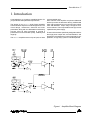
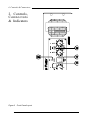
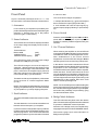
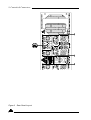
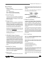
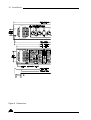
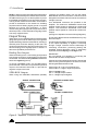
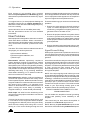
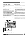
AM1200
Operation Manual
IMPORTANT!
Please read carefully.
This operation manual contains important information regarding
safety precautions, installation, performance, operation and
maintenance of your AM1200 power amplifier. You should
familiarize yourself with the contents of this
manual before operating your amplifier.
Safety Precautions
and Labelling
The rear panel of the unit has a number of markings and
internationally recognized symbols related to the
hazards and precautions that should be taken when
operating MAINS connected equipment.
The presence of a LIGHTNING FLASH with an arrowhead
contained within the boundaries of an equilateral triangle
is intended to alert the user that dangerous uninsulated
voltages may exist within the unit's enclosure. These
voltages may be of a sufficient magnitude as to
constitute the risk of an electrical shock.
This symbol is reinforced with the text:
!CAUTION!
RISK OF ELECTRICAL SHOCK
DO NOT OPEN
The presence of an EXCLAMATION MARK contained
within the boundaries of an equilateral triangle is
intended to alert the user that there is important
operating and maintenance literature that accompanies
the unit.
!WARNING!
DO NOT EXPOSE TO EITHER
RAIN OR MOISTURE
The unit should not be operated in a situation where it
may encounter the entry of water, rain, or any fluids. To
expose the unit to the above conditions may make the
operation of the unit hazardous and increase the risk
of electrical shock.
REFER SERVICING TO
QUALIFIED PERSONNEL.
NO USER SERVICEABLE
PARTS INSIDE.
The user should not attempt to service the unit. Only
qualified and knowledgeable personnel familiar with
the internal workings of the unit should attempt any
repair, servicing or authorized modification to the
unit. The unit does not contain any parts which the
user can service or re-use in this or any other product.
If you are in need of special assistance and the
information you require is outside the scope of this
manual, please contact your nearest service agent or
Australian Monitor direct:
THE TECHNICAL OFFICER
AUSTRALIAN MONITOR
C/- AUDIO TELEX COMMUNICATIONS PTY LTD
PRIVATE BAG 149,
SILVERWATER. N.S.W. 1811
AUSTRALIA.
Local
International
Phone
(02) 9647-1411
61-2-9647-1411
Fax
(02) 9748-2537
61-2-9748-2537
Email
Internet
[email protected]
www.australianmonitor.com.au
Features:
- 4, 3 or 2 channel operation.
- Input signal strapping (loop through) connectors.
- Custom designed, 3RU heavy duty alloy chassis.
- Active balanced inputs.
- Modular construction.
- 21 Position detented attenuators.
- Symmetrical layout - even weight distribution.
- Massive heat-sink / heat-exchangers.
- Linear, well-regulating, high current power supply.
- Efficient front to back cooling.
- Dual isolated high current secondaries.
- Dual, twin speed axial fans.
- High efficiency toroidal mains transformer.
- Front and rear carry handles.
- Continuous high power capability.
- Front and rear mounting points.
- Lateral Mosfet Class AB output stage.
- High-quality, close-tolerance components used
- Binding post and Neutrik "Speakon" output
throughout.
connection.
Protection Features
- Suppression of inrush current at mains turn-on.
- Mains Circuit Breaker.
- Input muting at turn-on.
- Independent DC supply rail fuses per channel.
- Input overvoltage protection.
- Layout, grounding, decoupling and componentry
- Radio-frequency interference suppression.
have been optimized to provide the user with
- Thermal protection and indication.
stability, reliability and longevity.
- Short-circuit protection and indication.
Contents
Page
1.
2.
3.
4.
5.
6.
7.
Introduction
Controls, Connectors and Indicators
2.1 Front Panel
2.2 Rear Panel
Installation
Operation
Bridge Mode
Two Ohm or Not Two Ohm
Maintenance
5
6
7
9
11
13
15
16
17
8.
9.
Warranty
Specification
18
19
List of Illustrations
Page
Figure 1. Block Diagram
Figure 2. Front Panel Layout
Figure 3. Rear Panel Layout
Figure 4. Case Dimensions
Figure 5. "Speakon" Connector Wiring
Figure 6. Bridge Mode Speaker Wiring
5
6
8
10
12
15
Introduction 5
1. Introduction
Congratulations on choosing Australian Monitor for
your professional amplification requirements.
The design of your AM1200 Audio Power Amplifier
embraces all the aspects of a well designed unit. The
visual design, mechanical, electrical and sonic
parameters, along with our dedicated manufacturing
process, have all been optimized to provide a
professional tool that exhibits quality, reliability and
longevity.
The AM1200 amplifiers are 3 unit (5.25") tall, 19" wide
rack mountable units.
Each channel of the amplifier comprises a balanced
active input with an attenuator driving a differential
class A drive stage which in turn drives a fan-cooled,
class AB MOSFET output stage configured as a
source follower. The unit operates from a high current
capable linear power supply.
These units have been specifically designed to deliver
their high power output with minimal distortion, and
provide the critical degree of control required by your
speakers, at high duty cycles for extended periods.
Figure 1 Amplifier Block Diagram
6 Controls & Connectors
2. Controls,
Connectors
& Indicators
Figure 2 Front Panel Layout
Controls & Connectors 7
Front Panel
is 2 ohms or less.
Figure 1 shows the panel layout of the AM1200. The
functions of the controls and indicators are as follows:
1. Attenuator
Level control for your amplifier is provided by a 21
position detented potentiometer and indicates gain
reduction in decibels from the 0 dB position
(maximum gain, no attenuation).
2. Status Indicator
This is a dual colour LED which displays the status
of the output stage and displays three levels of
operation.
These levels are:
Below -20dB
-20dB and above
1dB below actual clipping
(unlit)
(green)
(red)
The LED will turn green once the output voltage
exceeds the -20dB point (3.5 volts).
The LED will change to red once the output exceeds the -1dB point before actual clipping of the
amplifier’s output stage. The threshold of the -1dB
point is referred to the amplifier supply rails and
alters with changes in the mains supply, changes
in the load and duty cycle fluctuations.
The attack and decay time (ballistics), of the status
circuit are those of a Peak Programme Meter
(P.P.M.)
NOTE: The amplifier is not damaged by running into
clipping, but speakers may be. To maximise the life
of your speakers, try to keep clipping infrequent.
3. Fault Indicator
This amber LED will illuminate when a fault condition
exists.
The fault detection circuit monitors the difference
between drive and output in your amplifier.
If you have a short on the speaker output (or a blown
negative rail fuse) the LED will flash brightly in sync
with the programme. This LED will also flash with
programme peaks for gross overloads or if the load
The circuit has two stages of operation:
1. It will provide indication (e.g. gross overload) but
does not affect the input signal (a faint flash).
2. It will indicate and mute the input signal (e.g.
shorted output) (brightly flashing or permanently
on).
4. Power Switch
Press the switch DOWN for power ON and UP for
power OFF. At start-up (turn-on) the input to the
amplifier is muted by 30dB for approximately two
seconds.
5. On / Thermal Indicator
When switching the amplifier on, this red LED will
momentarily flash Red, indicating correct operation
of the Mains In-Rush Current Suppression circuit.
After establishment of the Inrush Current
Suppression circuit the LED will change to Green
indicating the unit is on and receiving mains power.
In the advent of a thermal overload this LED will
illuminate red indicating that the internal operating
temperature of one or all amplifier channels has
exceeded a safe level of operation and the amplifier
will be shut down. The fans will continue to run and
once the amplifier has cooled down sufficiently, the
amplifier will start up automatically providing Inrush
Current Suppression and input signal muting until
establishment of the amplifier after which it will
return to normal operating mode.
NOTE: You should always ensure that the fan grille
is kept clean and free from the build up of dust and
lint. This will ensure longer operation of your amplifier
and reduce the possibility of it prematurely going
into thermal shutdown mode.
6. Bridge Mode Indicator
This LED will illuminate yellow when the relative
pairs of channels of the amplifier have been selected
to operate in a "BRIDGE" mode of operation.
Selection of the bridge mode is accomplished by
engaging the rear panel "PUSH TO BRIDGE" Switch.
See section 5 (page 15) for more information on
Bridge mode operation.
8 Controls & Connectors
Figure 3 Rear Panel Layout
Controls & Connectors 9
Rear Panel
7. Balanced Input
A female 3-pin XL type connector is provided on
each input:
Pin 1 = Signal Ground;
Pin 2 = Hot (non-inverting or in phase);
Pin 3 = Cold (inverting or reverse phase).
7a.Signal Strapping
A male 3-pin XL type connector is provided on
channels A and D and is wired in parallel with the
female input XLR for strapping / looping signal
between amplifiers.
8. Bridge Switch
Pushing this switch in engages the BRIDGED/
MONO mode of operation for the relative pair of
channels. In this mode, your amplifier will only
accept signal applied to the Channel-A input XLR
(for channels A and B) or signal applied to the
Channel-D input XLR (for channels D and C).
Channel-A will now control the level of the A/B
bridged pair and Channel-D will now control the
level of the D/C bridged pair.
Speaker termination should be sourced from the
red binding-post outputs.
9. SPEAKON Output Connector
The NEUTRIK (NL4MP) 4 way SPEAKON connector
is provided as the main speaker output termination.
This emerging standard of loudspeaker to amplifier
connection allows access to both channels of the
amplifier via the one connector for bi-amp
applications. Channel-A (or D) is considered the
dominant channel and has both channels wired to
the Speakon connector. See the installation section
of this manual for detailed information on Speakon
wiring.
9a.Binding Post Outputs
Binding posts (banana jacks) are provided for
speaker output termination with banana plugs or
bare wire. The red post is used as positive and the
black post is used as negative.
10.Mains Lead
Your amplifier is supplied with a heavy duty mains
lead (power cord) appropriately rated for the mains
supply voltage marked on the rear panel of your
amplifier.
The wires in the mains lead are coloured in
accordance with the following code:
BROWN
BLUE
GREEN AND YELLOW
= ACTIVE;
= NEUTRAL;
= EARTH.
! CAUTION !
Your amplifier must always be earthed!
11.Mains Circuit Breaker
A “push to reset” thermal acting circuit breaker is
supplied on your amplifier providing overall protection
of your amplifier’s power supply and the
interconnecting mains. The breaker will isolate the
"active" mains conductor in the event of a high
current internal fault or in continued overload
conditions.
The breaker will not be able to be reset immediately
after tripping. A cool down period of around 30
seconds is required before the breaker will reset
back into circuit. If the breaker "trips" immediately
after a reset, then a fault may have developed within
the amplifier.
12.D.C. Rail Fuses
Your AM1200 amplifier is fitted with 8 Amp fuses per
rail - per channel, as overload protection for the
output stage of your amplifier.
These fuses are in series with the high current
supply rails to the amplifier's output stage and will
blow when:
1) An internal fault exists;
2) There is a sustained overload;
3) There is a sustained short circuit;
4) Sustained load fault.
Note: The front panel Fault Indicator will illuminate
and pulse in sync. with the program source if the
negative supply Rail fuse blows.
Distortion will result and the front panel Status LED
will illuminate RED if the Positive Rail fuse blows.
Replace only with 8 Amp, 3AG fast acting type
fuses.
10 Installation
Figure 4 Dimensions
Installation 11
3. Installation
Mains Lead Wiring
WARNING
Your amplifier must be earthed at all times!
When you first receive your amplifier it may not have
a mains plug attached. You must ensure that an
appropriate plug is used and corresponds with the
amplifier’s current (ampere) requirements and meets
the approval of your local energy authority.
Please refer termination of this lead to qualified
personnel. Australian Monitor takes no
responsibility for any damage or harm resulting
from improper termination of this lead!
The wires in the mains lead are coloured in accordance
with the following code:
GREEN AND YELLOW = EARTH
Connect to the terminal marked with the letter E, with
the EARTH SYMBOL or coloured GREEN.
BLUE = NEUTRAL
Connect to the terminal marked with the letter N (or
coloured WHITE in USA and Canada, or coloured
BLACK in the United Kingdom).
BROWN = ACTIVE (LIVE)
Connect to the terminal marked with the letter A or L
(or coloured BLACK in USA and Canada or coloured
RED in the United Kingdom).
Power Requirements
Mains Voltage
100 to 120 volts
220 to 240 volts
Circuit Breaker Rating
20 Amps
10 Amps
Power Consumption at idle
Consumption at rated 4 ohm power
= 250 Watts
= 2300 Watts
Ensure that your mains voltage is the same as the rear
panel mains voltage marker (+/- 10%).
Mounting
We recommend that you provide additional support for
the amplifier, especially if road use is planned, as the
weight can bend some racks otherwise. This support
can be provided by secure shelving, support rails or a
rear rack mounting strip to match up with the rear rack
mount points provided on your amplifier.
Cooling
Each pair of channels in your AM1200 amplifier is
cooled by an axial fan which draws cool air from the
front of the unit and expels the heated air via the rear
of the unit. These units offer two speed fans which run
at half speed, switching to full speed when the internal
heatsink temperature exceeds 600 C (1280 F).
An unrestricted airflow into and out from the unit must
be provided. Any restriction of the air flow will cause
heat to build up within the unit and possibly force the
unit into its thermal shutdown mode.
If the units are to be operated in an environment
where the airflow is restricted such as sealed racks or
even when running 2 ohm loads, the cooling should
be supplemented by extra cooling fans to evacuate
the heated air and aid the flow of cool air through the
unit.
Input Wiring
IMPORTANT! Do not directly connect pin 1 on the
amplifier’s input or strapping XLR, to the amplifier’s
chassis, speaker ground or power ground!
NOTE: Input signal ground is not to be used as
a safety ground (earth).
The input to your amplifier is a balanced 3-pin system
and requires all three pins to be connected. Only high
quality twin-core shielded cable should be used.
When wiring for a balanced source the connector
going to the input of your amplifier should be wired as
follows:
Pin 2 = HOT (In Phase - non inverting).
Pin 3 = COLD (Reverse Phase - inverting).
Pin 1 = GROUND / SHIELD.
Your amplifier is designed for standard 19" rack
mounting and occupies 3 EIA rack units (5.25"). The
mounting centres are:
When wiring from an unbalanced source you must
ensure that pin 3 is connected to pin 1 (input ground),
either by linking the pins in the input connector or by
the source equipment's output wiring.
Vertical:
When wiring for an unbalanced source:
2.25" (57.15mm)
Horizontal: 18.15" (461.1mm) to 18.62" (473.0mm).
The slots in the mounting flange will accept bolt
diameters up to 1/4" (6.35mm).
Pin 2 = HOT (in phase with the amplifier’s output),
Pin 3 = GROUND/SHIELD (joins to pin 1).
Pin 1 = GROUND/SHIELD
12 Installation
NOTE: In-line XLR connectors often have a termination
lug that connects directly to the chassis of the connector.
Do not link this lug to pin 1 at the amplifier’s input as
it will defeat the amplifier’s input grounding scheme.
This lug is often referred to as a "drain” and is used to
provide a termination to the chassis for shielding
purposes when a floating signal ground is required
between the source and destination, or when
disconnecting the signal ground is required to reduce
earth loop noise, or noise induced into signal grounds
from stray magnetic fields.
Output Wiring
When wiring to your speakers always use the largest
gauge wire your connector will accept. The longer the
speaker lead the greater the losses will be, resulting in
reduced power and less damping at the load. We
recommend using a heavy duty two core flex (four core
flex if bi-amping) 10 to 12 gauge (2mm2 to 2.5mm2 or
50/0.25 or equivalent) as a minimum.
Binding Post Outputs
When terminating to the 4 mm binding post (banana
jack) output connectors, banana plugs or bare wires
can be used. The red terminal is positive and the black
terminal is negative (ground).
If running in BRIDGE mode, only the red binding
posts are used. Channels A or D provide the positive
output to the load and channel B or C provide the
negative output to the load.
SPEAKON Outputs
When using the NEUTRIK SPEAKON (NL4MP)
connector for speaker output, use only the mating
NEUTRIK NL4FC in-line connector. This connector is
designed so that both channels can be sourced from
a single connector.
Four SPEAKON connectors are provided on the
amplifier. The Channel-A SPEAKON carries both
speaker output signals for Channel-A & Channel-B
outputs. The Channel-D SPEAKON carries both
speaker output signals for Channel-D & Channel-C
outputs.
(see Figure 5: Speakon Connector Wiring Diagrams).
The Channel-B and Channel-C SPEAKON carry only
their own output.
This arrangement allows you the option of connecting
to the outputs separately or together. Connecting
through a single connector has the advantage of
minimising connections, preserving phasing and
simplified channel allocation, which is particularly
important when bi-amping or in bridge mode.
IMPORTANT
Do not overload your amplifier by connecting the
Channel-B or Channel-C output twice!
Channel-A or D is used as the “dominant” channel and
when sourcing a dual output from Channel-A or D the
following standard should be used:
Channel-A or D = Left or Low Frequencies.
Channel B or C = Right or High Frequencies.
When in bridge mode:
Pin 1+ = Bridge Output Positive
Pin 2+ = Bridge Output Negative.
SINGLE CONNECTION
BRIDGED CONNECTION
DUAL CONNECTION
BI-AMP CONNECTION
Figure 5. "Speakon" Connector Wiring Diagram
Operation 13
4. Operation
IMPORTANT
All signal source equipment should be adequately
earthed. This not only ensures your safety but
everybody else's as well. Faults can and do occur in
mains connected equipment where the chassis can
become “live” if it is not properly earthed. In these
instances the fault in a “floating” (un-grounded) piece of
equipment will look for the shortest path to ground
which could possibly be your amplifier's input. If the
fault current is large enough it will destroy the input to
your amplifier and look for the next available path,
which may be you!
Before making any connections to your amplifier
observe the following:
1. Ensure the mains voltage supply matches the label
on the rear panel of your amplifier (+/- 10%).
2. Ensure that the power switch is OFF (UP)
3. Ensure that all system grounds (earths) are
connected from a common point. Avoid powering
equipment within a system from multiple power
sources that may be separated by large distances.
4. Check the continuity of all interconnecting leads to
your amplifier, ensure that there are no open or
short circuited conductors.
5. Ensure that the power handling of your load
(speakers) can adequately cope with the power
output of the amplifier.
Very Important
Due to the high power ability of the AM1200 you need
to be aware that certain precautions need to be
followed to ensure longevity of your amplifier:
- Never turn your amplifier on unless all connections
(inputs and speakers) have been made!
- Never plug in a signal lead after the amplifier has
been turned on! Turn the unit off first.
- Never drive the output into clipping if the load is
open circuit or there is no speaker load connected!
Powering Up
REMEMBER
The amplifier should be the last piece of equipment that
you turn on and the first piece of equipment that you
turn off.
We recommend turning the attenuators on your
amplifier down when turning the unit on.
When you power up your amplifier, your amplifier
goes through an establishment period before it will
accept signal. The Inrush Current Suppression (ICS)
circuit is in operation for the first 0.5 seconds. This
limits the mains current to prevent "nuisance tripping"
of circuit breakers.
During this period the THERMAL LED will flash red
whilst the mains voltage gradually charges up the
power supply. You will then hear a relay “click”,
indicating mains is now directly applied to the amplifier.
While the ICS circuit operates there is also a 30dB
mute on the signal input. After two seconds this mute
will release, allowing any applied signal to pass
unattenuated.
When switching the amplifier off, wait a couple of
seconds before switching the unit on again. This allows
the ICS circuit to reset.
Level Matching
The normal operating position for the attenuator is
the "0 dB" position (fully clockwise, no attenuation).
In this position the amplifier operates at full gain.
Turning the attenuator back (anticlockwise) reduces
the input sensitivity by the amount marked on the
attenuator scale (dial).
NOTE: If full power output is required you should
operate your amplifier with the front panel attenuator
above the -15dB position, otherwise clipping of the
input circuitry and its resultant distortion will occur
before full output power is achieved.
Sensitivity
Your amplifier is a linear device operating with a fixed
input to output voltage gain (less attenuation). The
maximum output voltage swing is determined by the
applied mains voltage, load, load type and the duty
cycle of the applied signal.
The voltage gain factor of your amplifier is: 37 times or
31.4dB.
The input sensitivity for your amplifier when the
attenuator is at the “0” dB attenuation position (fully
clockwise) is nominally:
+3.0dBu (1.10volts in) for rated power into a 8 ohm
load.
+1.6dBu (0.93 volt in) for rated power into a 4 ohm
load.
14 Operation
Each channel of your amplifier has a nominal
balanced input impedance of 18k Ohms (@1kHz)
and should not present a difficult load for any signal
source.
produces a voltage drop due to the wire’s resistance.
This voltage difference between the amp earth and
source equipment earth appears to the amplifier's
input as a signal and is amplified as hum.
Your signal source (i.e. the equipment feeding the
amplifier) should have an output impedance of
600 Ohms or lower to avoid unwanted high frequency
loss in the cabling.
There are three things you can do to avoid earth loop
problems:
Input overload occurs at +20.5dBu (8.25 volts).
See the specification section for more detailed
information.
Hum Problems
Most equipment is designed for minimum hum when
used under ideal conditions. When connected to
other equipment, and to safety earth in an electrically
noisy environment however, problems will often
occur.
The three "E"s of hum and hum related noise which
can plague your audio system are:
a) Electrostatic radiation,
b) Electromagnetic radiation, and
c) Earth loops
Electrostatic radiation capacitively couples to
system elements causing an interference voltage
that mainly affects higher impedance paths, such
as amplifier inputs. The source is generally a nearby
high voltage such as a mains lead or a speaker lead.
The problem can usually be reduced by moving the
offending lead away, or by providing additional
electrostatic shielding (i.e. an earthed conductor
which forms a barrier to the field).
Electromagnetic radiation induces interference
currents into system elements that mainly effect
lower impedance paths. Radio transmitters or stray
magnetic fields from mains transformers are often
the cause of this problem. It is generally more
difficult to eliminate this kind of interference, but
again, moving the source away or providing a
magnetic shield (i.e. a steel shield) should help.
Earth loops can arise from the interfacing of the
various pieces of equipment and their connections
to safety earth.
This is by far the most common cause of hum, and
it occurs when source equipment and the amplifier
are plugged into different points along the safety
earth where the safety earth wiring has a current
flowing in it. The current flowing through the wire
1. Ensure your mains power for the audio system is
“quiet” i.e. without equipment on it such as airconditioning, refrigeration or lighting which may
generate noise in the earth circuit.
2. Ensure all equipment within the system shares
a common ground/ safety earth point. This will
reduce the possibility of circulating earth currents
as the equipment will be referenced to the same
ground potential.
3. Ensure that balanced signal leads going to the
amplifier are connected to earth at one end only.
Signal Ground Lifting
When proper system hook-up has been carried out,
you may still have some hum or hum related noise.
This may be due to any of the previously mentioned
gremlins.
One of the most effective ways to reduce earth loop
or electromagnetically induced hum is to disconnect
input signal ground at the input connector of your
amplifier. This effectively breaks the earth loop path
or open circuits the input ground path so no
electromagnetically induced currents can flow
through the amplifier.
NOTE: If the input signal ground is lifted you must
ensure adequate shielding of the input wiring. If the
signal source equipment does not provide adequate
shielding (i.e. a definitive connection to ground) you
must disconnect the shield from the input connector's
ground pin (Pin-1) and reconnect it to the "drain"
contact on the input connector. This will ensure the
shield on your input wiring actually goes to the
amplifier chassis and subsequently to earth.
DO NOT CONNECT PIN-1 DIRECTLY TO THE
DRAIN CONNECTION.
You will defeat the amplifiers internal grounding
scheme and possibly cause instability to the
amplifier.
This should only be done when the amplifier is
operated from a balanced signal source.
NOTE: Be wary of quasi-balanced outputs, these
are often no more than floating unbalanced outputs.
Bridge Mode 15
5. Bridge Mode
The term BRIDGE is used when two independent
amplifier channels are used to drive the same load. The
load is in series (a bridge) between the two amplifier
channels.
up your amplifier for running it in BRIDGE mode.
Whilst the amplifier is off,
1. Connect the signal source to the Channel-A (or D)
female input XLR. The Channel-A (or D) attenuator
becomes the level control for both channels.
2. Engage the “push to bridge” switch.
Channel A is used as the "dominant" channel and its
output is in phase with the input signal, and channel
B has its phase reversed so it is exactly 1800 out of
phase with the input signal.
As two amplifiers with a phase difference of 1800 are
now driving the load you will now have double the
voltage into the load. This means you will now have four
times the power into that load. The output can now be
considered as an active balanced output.
A common use of an amplifier in BRIDGE mode is for
driving 70 volt & 100 volt distribution lines. In BRIDGE
mode, The AM1200 can produce over 70 volts with line
impedances greater than 8 ohms and over 80 volts with
line impedances greater than 16 ohms.
Equally the units can be used in bridge mode to provide
the correct voltage/power requirements for an applicable load.
As shown in Figure 6, there are three steps in setting
Figure 6 Bridge Mode Speaker Connection
3. Connect your load between the red binding post
output terminals, where the positive side of the
load is connected to the channel A (or D) output
(marked BRIDGE+) and the negative side of the
load goes to the channel B (or C) output (marked
BRIDGE-). There are no further connections required.
You can also source the output from the Channel-A (or
D) SPEAKON output connector where Channel-A (or
D) will be on the pin marked 1+ and Channel-B (or C)
will be on the pin marked 2+.
NOTE: You should check after market manufactured
Speakon interconnecting speaker leads before connecting them to your amplifier. Some leads are manufactured for specific purposes, or specific use, and
may have pins shorted inside the connector. Any
speakon lead with shorted pins will obviously short the
output of your amplifier (either to ground, or output to
output - be careful).
16 Two Ohm or Not Two Ohm
6. Two Ohm or
Not Two Ohm
NOTE: Ensure adequate ventilation and monitor the
FAULT indicators to guard against thermal shutdown
when driving two ohm loads.
A preamble.
The load that a loudspeaker presents to an amplifier is
very complex and at different frequencies can be
inductive, capacitive, resistive, or a combination of
these (reactive). With the complex interaction of these
attributes, which alter from loudspeaker to loudspeaker,
a definitive load for an amplifier does not really exist.
Loudspeakers operating within an enclosure are
specified with a nominal impedance. This nominal
impedance is only a rough guide to the load it presents
to an amplifier.
As an example, a loudspeaker with a nominal impedance
of say 8 ohms, may have an impedance of over 50
ohms at resonance (bass frequencies), drop to less
than 6 ohms after the resonance peak (through its mid
band area) and then increase to over 16 ohms for higher
frequencies.
A 4 ohm load makes an amplifier work "harder" than an
8 ohm load at the same voltage, as double the current
is required.
Though various loudspeakers may be marked with the
same nominal impedance, some loads are more difficult
than others.
Bass frequencies usually exhibit higher impedances
and require higher voltages to achieve the desired
result. They also reflect higher energy back to the
amplifier simply due to the amount of cone excursion
involved at lower frequencies.
The Mid frequency band usually offers the lowest
impedances and the highest duty cycles requiring both
high voltage and high current.
The High frequency region usually offers a moderate
impedance and usually does not need much voltage
but the instantaneous current demand can be much
greater than you think.
As well as this burden on the amplifier, the transient
waveforms found in actual use can demand a lot more
current than the "steady-state" sinewaves used in
most amplifier bench tests.
The power output of your AM1200 amplifier quoted on
the specification sheet is derived from a voltage
excursion into a resistive load for a sine wave at a given
frequency. Though this method is in line with the
various standards that exist, it only gives an indication
to the maximum voltage swing (before clipping) for a
given load. This method of rating power does not give
an indication of the current (Ampere) capability of the
amplifier, nor does it show the amplifier’s ability to
sustain high energy waveforms.
Your AM1200 amplifier has been specifically designed
to be able to deliver more than twice the current than
that shown on the specification sheet to cope with
difficult loads and/or high energy waveforms.
This extra current reserve is the result of over engineering
and is the headroom the amplifier utilizes to control the
loudspeaker and deal with the “reactive energy” from
the loudspeaker load that has to be dissipated within
the amplifier.
Your AM1200 amplifier is able to drive 2 ohm loads or
operate in BRIDGE mode into 4 ohms. The operator
must be aware that when driving 2 ohm loads or bridged
4 ohm loads that the currents running in the output
stage are very large and will cause greater heat build
up within the amplifier than higher impedance loads.
The Front Panel FAULT Indicators can be used to
provide an indication of the "difficulty" of the load and
will give the operator an indication of the heat build up
in the output stage.
If the fault indicators flash with the "clip" LEDs or do not
illuminate until well into clipping then the load can be
considered as normal or easy.
If the fault indicator starts to flash before the "clip"
LEDs then the load should be considered complex
and/or difficult.
For the more complex and/or difficult loads, the
illumination of the "fault" LED on programme peaks
should be interpreted as the output level limit. Driving
the output continuously past this point could result in
muting of the output stage, breakers tripping or
premature thermal shutdown.
The fault detection circuit is also thermally
compensated, and fault indication will occur earlier
when the unit is hot. If the "fault" LED continually
lights earlier than normal, then the unit is heating
up. If the signal level is not reduced to compensate
for the heating of the unit then thermal shutdown
may occur.
Maintenance 17
7. Maintenance
Your A M 1 2 0 0 amplifier will need minimal
maintenance. No internal adjustments need to be
made to the unit to maintain optimum performance.
To provide years of unhindered operation we suggest
a maintenance inspection be carried out on a regular
basis, say every 12 months or so.
Fans
Due to the openness of the air path through your
AM1200 amplifier, very little dust should settle
within the amplifier. The unit has been designed so
that any dust and/or foreign particles that do settle
within the amplifier will not unduly hinder the cooling
of the unit.
The mesh grille in front of the fans will act to limit the
amount of dust and lint entering the unit. You will
find in time that there will be a build up of dust and
lint on the grille which may start to hinder the airflow
through the unit. You should periodically remove the
dust and keep the grille clean.
Over time, dust may build up on the leading edge of
the fan blades and reduce their cooling efficiency.
The time taken for this to happen will depend on the
environment and the amount of use.
The fan blades are accessible once the lids are
removed and can be easily cleaned. You need only
hold the fan rotor still and wipe the dust off the
blades. Many users stall the fan and use
compressed air to blow the dust off the fan blades.
It is important to note that the fan blades must be
held still whilst blowing air over the blades otherwise
you may burn out the bearings in the fan.
NOTE:
Make sure the unit is off and is unplugged from the
mains. Give the main filter capacitors time to discharge
before removing lids and inspecting the fans.
Fuses
There are eight (8) rail fuses provided on the back panel
of the unit. These rail fuses are in series with the
positive and negative output supply to each amplifier
channel and provide overall protection for the output
stage. If the amplifier is subjected to heavy use such
as short circuits, 2 ohm or bridged 4 ohm loads, these
fuses will eventually fatigue and may require replacing
to ensure they do not fail at an inconvenient time.
You should replace the fuse if the element is sagging
or discoloured. Only ever replace with the same type
fuse and current rating.
When checking for a failed fuse, do not rely on visual
inspection alone. You should use an ohmmeter to
check continuity.
NOTE:
Make sure the unit is off and is unplugged from the
mains and give the main filter capacitors time to
discharge before replacing fuses.
Only competent or qualified persons should
attempt any service or maintenance of your amplifier!
18 Warranty
8. Warranty
Australian Monitor warrants the original purchaser of
each AM1200 amplifier (purchased at an authorised
Australian Monitor dealer) that it will be free from
defects in materials and workmanship for a period of
two (2) years from the original date of purchase.
Australian Monitor will, at its option, repair or replace
any unit or component covered by this warranty
which becomes defective or malfunctions under
normal use and service during the period of this
warranty, at no charge for parts or labour to the
original owner.
This warranty does not cover thermal problems
due to obstructed airflow, or defects or malfunctions resulting from accidents, misuse, abuse,
operation with the incorrect AC mains voltage,
connection to faulty equipment, modification or
alteration without prior factory approval or service
by unauthorised personnel.
It is the owner's responsibility to ensure that normal
maintenance inspections are carried out at regular
intervals as recommended in the maintenance section
of this manual. Australian Monitor reserves the right
to refuse warranty service where the owner fails to
take reasonable care in use and maintenance of the
amplifier.
To validate this warranty, the original purchaser must
complete and mail the warranty registration card
directly to Australian Monitor within fourteen (14)
days of purchase.
To obtain warranty service, the equipment should be
shipped to an authorised Australian Monitor dealer or
direct to Australian Monitor. Freight to Australian
Monitor is at the owner's expense.
Units with a defaced serial number will not be accepted
for warranty service. Any evidence of alteration,
erasure or forgery of the purchase receipt will also
void this warranty.
Australian Monitor accepts no liability for any
consequential damages, whether direct or
indirect, arising from the use or misuse of its
products.
Australian Monitor reserves the right to alter its
designs and specifications at any time without notice
or obligation to previous purchasers.
AM-SERIES 2 YEAR WARRANTY REGISTRATION
IMPORTANT
Please complete this card and return it immediately after unpacking the product.
This card is to be sent DIRECTLY to Australian Monitor.
NOTE! Warranty is effective ONLY upon receipt of this card.
COMPANY
NAME
MODEL
ADDRESS
SERIAL No
DATE PURCHASED
CITY
STATE
DEALER
CODE
COUNTRY
Ensure that you fill out and send your warranty registration card.
Use this copy to record a duplicate of the details.
Specification 19
AM1200Specifications
General
The AM1200 will deliver or exceed - 200 watts RMS into an 8 ohm load - 300 watts RMS into a 4 ohm load - 600
watts RMS bridged into an 8 ohm load *for a single, pair, or all four channels being driven continuously (with less
than 0.05% IMD and THD from 1 watt to rated power) from 20Hz to 20kHz.
Output Condition
Output Power
E.I.A. Power @ 1 kHz, <0.05 % THD+N.
8 ohm
4 ohm
2 ohm
Single channel driven.
All channels driven.
220W
200W
370W
320W
450W
-
Bridge mode @ 1 kHz, <0.05 % THD+N.
16 ohm
8 ohm
4 ohm
Single pair (C & D only)
Both pairs
410W
400W
670W
640W
800W
-
Dynamic Power @ 1 kHz, at onset of clipping,
20 cycles @ 0dB, 480 cycles @ -20 dB.
Single channel driven re 4 ohm
Bridged pair driven re 8 ohm
Bridged pair driven re 4 ohm
Distortion
THD+N
IMD SMPTE
IMD DIM 30
(0.5 dB below clipping re 4 ohms)
(@ 1 kHz)
<0.003%
(60 Hz & 7 kHz 4:1)
<0.015%
(3.15kHz square & 15 kHz) <0.008%
Output Impedance @ 1 kHz
410 Watts
750 Watts
1000 Watts
Input Sensitivity (nominally)
For rated power re 8 ohm
For rated power re 4 ohm
Voltage Gain
1.10 Vrms (+3.0 dBu)
0.92 Vrms (+1.5 dBu)
37 times (31.4 dB)
<0.011 ohms
Input CMRR
Damping Factor @ 1 kHz re 8 ohms
>720:1
@ 1 kHz (re 8 ohm rating)
Output Rise Time
<2.2µS
Signal / Noise ratio
>90 dB
(80%, leading edge of 20kHz square wave)
"A" weighted (re 8 ohm rating)
>60V per µS
(leading edge, 20kHz square wave @ clipping)
Crosstalk
Frequency Response
Weight Net 57.2 lb (26kg), Shipping 63.8lb (29kg)
Slew Rate
20 Hz - 20 kHz
-3dB points
< -0.3, -0.15 dB
5 Hz - 140 kHz
Input Impedance
Line to Line (Balanced)
@ 1 kHz (re 8 ohm rating)
Dimensions
excluding handles
including handles
18k ohms
H
x W x D
133 x 483 x 375
133 x 483 x 460
>101 dB
>90 dB
(mm)
(mm)
(19 inch EIA rack mounting, 3 units high)
Test conditions
Input source = 600 ohm, Balanced and ground referenced (CMRR test had floating ground & 50 ohm
source). Mains regulated to 240 volts / 50hz. All measurements taken at binding post output terminals.
Standard production units measured. No compensation applied.
www.australianmonitor.com.au
Distributed by:
Audio Telex Communications Pty Ltd
ACN 001345482
www.audiotelex.com.au
International Enquiries
Ph: 612 9647 1411, Fax: 612 9748 2537, E-mail: [email protected]
Sydney
Ph: (02) 9647 1411, Fax: (02) 9648 3698, E-mail: [email protected]
Melbourne
Ph: (03) 9890 7477, Fax: (03) 9890 7977, E-mail: [email protected]
Brisbane
Ph: (07) 3852 1312, Fax: (07) 3252 1237, E-mail: [email protected]
Adelaide
Ph: (08) 8352 4444, Fax: (08) 8352 4488, E-mail: [email protected]
Perth
Ph: (08) 9228 4222, Fax: (08) 9228 4233, E-mail: [email protected]
Auckland
Ph: (09) 415 9426, Fax: (09) 415 9864, E-mail: [email protected]
2000