1
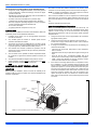
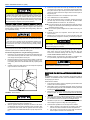
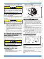
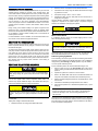
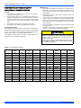
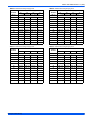
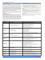
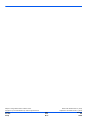
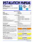
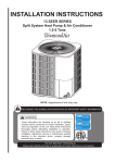
INSTALLATION MANUAL
TI
FI
ED
T O ARI
C
ER
PL
-C
RY
UN I
NI N G
G W IT H
OI
IT
TA
Y
D
ON
MA N U F A C T U R
AS
AIR
NI
ER
M
C
O
R-410A
OUTDOOR SPLIT-SYSTEM
AIR CONDITIONING
R
RT
IF
RI
I CA
T
F
U I P M EN T
O
EQ
E
C
A
T IO
NS
I ON S E C
10
S T A NDA R D 2
CERTIFICATION APPLIES ONLY
WHEN THE COMPLETE
SYSTEM IS LISTED
WITH ARI.
MODELS: 15 SEER - CZE / AC5B / AL5B SERIES
2 TO 5 TONS
LISTED
This product was manufactured
in a plant whose quality system
is certified/registered as being
in conformity with ISO 9001.
TABLE OF CONTENTS
GENERAL . . . . . . . . . . . . . . . . . . . . . . . . . . . . . . . . . . . . . . . . . . . . . . 1
SAFETY . . . . . . . . . . . . . . . . . . . . . . . . . . . . . . . . . . . . . . . . . . . . . . . . 1
UNIT INSTALLATION . . . . . . . . . . . . . . . . . . . . . . . . . . . . . . . . . . . . . 2
INSTALLATIONS REQUIRING TXV . . . . . . . . . . . . . . . . . . . . . . . . . . 4
ELECTRICAL CONNECTIONS . . . . . . . . . . . . . . . . . . . . . . . . . . . . . . 5
EVACUATION . . . . . . . . . . . . . . . . . . . . . . . . . . . . . . . . . . . . . . . . . . .7
SYSTEM CHARGE . . . . . . . . . . . . . . . . . . . . . . . . . . . . . . . . . . . . . . .7
SYSTEM START-UP . . . . . . . . . . . . . . . . . . . . . . . . . . . . . . . . . . . . . .8
WIRING DIAGRAM . . . . . . . . . . . . . . . . . . . . . . . . . . . . . . . . . . . . . .11
LIST OF TABLES
R-410A Saturation Properties . . . . . . . . . . . . . . . . . . . . . . . . . . . . . . . . . . . . . . . . 8
15Z24AC Subcooling Charging Chart . . . . . . . . . . . . . . . . . . . . . . . . . . . . . . . . . 9
15Z36AC Subcooling Charging Chart . . . . . . . . . . . . . . . . . . . . . . . . . . . . . . . . . 9
15Z48AC Subcooling Charging Chart . . . . . . . . . . . . . . . . . . . . . . . . . . . . . . . . . 9
15Z60AC Subcooling Charging Chart . . . . . . . . . . . . . . . . . . . . . . . . . . . . . . . . . 9
Diagnostic Label . . . . . . . . . . . . . . . . . . . . . . . . . . . . . . . . . . . . . . . . . . . . . . . . 10
LIST OF FIGURES
Typical Installation . . . . . . . . . . . . . . . . . . . . . . . . . . . . . . . . . . . . . . . . . . . . . . . . 2
Tubing Hanger . . . . . . . . . . . . . . . . . . . . . . . . . . . . . . . . . . . . . . . . . . . . . . . . . . . 3
Underground Installation . . . . . . . . . . . . . . . . . . . . . . . . . . . . . . . . . . . . . . . . . . . . 3
Heat Protection . . . . . . . . . . . . . . . . . . . . . . . . . . . . . . . . . . . . . . . . . . . . . . . . . . . 4
Typical Field Wiring . . . . . . . . . . . . . . . . . . . . . . . . . . . . . . . . . . . . . . . . . . . . . . . 5
CFM Selection Board . . . . . . . . . . . . . . . . . . . . . . . . . . . . . . . . . . . . . . . . . . . . . . 5
Single Stage Non-Variable Speed Furnace (Y Connection Only) . . . . . . . . . . . . 6
Non-Variable Speed Furnace (Y1 & Y2 Connection) . . . . . . . . . . . . . . . . . . . . . 6
Typical Variable Speed Furnace/Air Handler Wiring . . . . . . . . . . . . . . . . . . . . . 6
N1AH, F2RP/F2FP, F2RC/F2FC Air Handler and 2-Speed Fan Kit Wiring . . . . . 6
Wiring Diagram . . . . . . . . . . . . . . . . . . . . . . . . . . . . . . . . . . . . . . . . . . . . . . . . . 11
SECTION I: GENERAL
The outdoor units are designed to be connected to a matching indoor
coil with sweat connect lines. Sweat connect units are factory charged
with refrigerant for the highest sales volume evaporator plus 15 feet of
field supplied lines.
Matching indoor coils are available with a thermal expansion valve or
an orifice liquid feed sized for the most common usage. The orifice size
and/or refrigerant charge may need to be changed for some system
combinations, elevation differences, or total line lengths. See tabular
data sheet provided in unit literature packet for charge requirements.
Refer to Application Data covering “General Piping Recommendations
and Refrigerant Line Length” (Part Number 036-61920-001).
SECTION II: SAFETY
This is a safety alert symbol. When you see this symbol on
labels or in manuals, be alert to the potential for personal
injury.
Understand and pay particular attention to the signal words DANGER,
WARNING, or CAUTION.
DANGER indicates an imminently hazardous situation, which, if not
avoided, will result in death or serious injury.
WARNING indicates a potentially hazardous situation, which, if not
avoided, could result in death or serious injury.
CAUTION indicates a potentially hazardous situation, which, if not
avoided may result in minor or moderate injury. It is also used to
alert against unsafe practices and hazards involving only property damage.
Improper installation may create a condition where the operation of
the product could cause personal injury or property damage.
Improper installation, adjustment, alteration, service, or maintenance can cause injury or property damage. Refer to this manual
for assistance or for additional information, consult a qualified contractor, installer, or service agency.
This product must be installed in strict compliance with the
enclosed installation instructions and any applicable local, state,
and national codes including, but not limited to building, electrical,
and mechanical codes.
R-410A systems operate at higher pressures than R-22 systems.
Do not use R-22 service equipment or components on R-410A
equipment. Service equipment Must Be Rated for R-410A.
INSPECTION
As soon as a unit is received, it should be inspected for possible damage during transit. If damage is evident, the extent of the damage
should be noted on the carrier’s delivery receipt. A separate request for
inspection by the carrier’s agent should be made in writing. See Local
Distributor for more information.
66901 / 035-20393-001 Rev. C (1204)
66901 / 035-20393-001 Rev. C (1204)
Requirements For Installing/Servicing R-410A Equipment
•
•
•
•
•
•
•
Gauge sets, hoses, refrigerant containers, and recovery systems
must be designed to handle the POE type oils and the higher
pressures of R-410A.
Manifold sets should be 800 PSIG high side and 250 PSIG low
side with 550 PSIG low side retard.
All hoses must have a 700 PSIG service pressure rating.
Leak detectors should be designed to detect HFC refrigerant.
Recovery equipment (including refrigerant recovery containers)
must be specifically designed to handle R-410A.
Do not use an R-22 TXV.
A liquid-line filter drier is required on every unit.
The outdoor unit must have sufficient clearance for air entrance to the
condenser coil, for air discharge, and for service access. See Figure 1.
NOTE: For multiple unit installations, units must be spaced a minimum
of 18 inches apart. (coil face to coil face.)
If the unit is to be installed on a hot sun exposed roof or a black-topped
ground area, the unit should be raised sufficiently above the roof or
ground to avoid taking the accumulated layer of hot air into the outdoor
unit.
Provide an adequate structural support.
ADD-ON REPLACEMENT/RETROFIT
The unit should be installed in accordance with all National, State, and
Local Safety Codes and the limitations listed below:
When this unit is being used as a replacement for an R-22 unit, it is
required that the outdoor unit, indoor coil, and metering device all be
replaced. Line-set change out is also recommended. The following
steps should be performed in order to insure proper system operation
and performance.
1.
Limitations for the indoor unit, coil, and appropriate accessories
must also be observed.
1.
Change-out of the indoor coil to an approved R-410A coil with the
appropriate metering device.
2.
Only variable speed air handlers or variable speed furnaces
should be used with these models.
2.
3.
The outdoor unit must not be installed with any duct work in the air
stream. The outdoor fan is the propeller type and is not designed
to operate against any additional external static pressure.
Change-out of the line-set when replacing an R-22 unit with an
R-410A unit is highly recommended to reduce cross-contamination of oils and refrigerants.
3.
If change-out of the line set is not practical, then the following precautions should be taken.
LIMITATIONS
4.
The maximum and minimum conditions for operation must be
observed to ensure a system that will give maximum performance
with minimum service.
5.
The unit should not be operated at outdoor temperatures below
60° F without an approved low ambient operation accessory kit
installed.
6.
The maximum allowable line length for this product is 75 feet.
7.
Indoor evaporator coil orifice must be removed prior to the installation of a factory supplied balanced port TXV kit.
SECTION III: UNIT INSTALLATION
LOCATION
Before starting the installation, select and check the suitability of the
location for both the indoor and outdoor unit. Observe all limitations and
clearance requirements.
•
Inspect the line set for kinks, sharp bends, or other restrictions,
and for corrosion.
• Determine if there are any low spots which might be serving as oil
traps.
• Flush the line set with a commercially available flush kit to
remove as much of the existing oil and contaminants as possible.
• Install a suction line filter-drier to trap any remaining contaminants, and remove after 50 hours of operation.
4. If the outdoor unit is being replaced due to a compressor burnout,
then installation of a 100% activated alumina suction-line filter
drier is required, in addition to the factory installed liquid-line drier.
Operate the system for 10 hours. Monitor the suction drier pressure drop. If the pressure drop exceeds 3 psig, replace both the
suction-line and liquid-line driers. After a total of 10 hours run time
where the suction-line pressure drop has not exceeded 3 psig,
replace the liquid line drier, and remove the suction-line drier.
Never leave a suction-line drier in the system longer than 50 hours
of run time.
THERMOSTAT
NEC CLASS 1
WIRING
TO INDOOR
BLOWER
NEC CLASS 2
WIRING
WEATHERPROOF
DISCONNECT SWITCH
48” OVERHEAD
CLEARANCE
TO COIL
SEAL OPENINGS WITH
PERMAGUM OR EQUIVALENT
24” SERVICE
ACCESS
CLEARANCE
18” FRONT
& SIDES
NOTE: ALL OUTDOOR WIRING MUST BE WEATHERPROOF
FIGURE 1: Typical Installation
2
Unitary Products Group
66901 / 035-20393-001 Rev. C (1204)
GROUND INSTALLATION
The unit may be installed at ground level on a solid base that will not
shift or settle, causing strain on the refrigerant lines and possible leaks.
Maintain the clearances shown in Figure 1 and install the unit in a level
position.
Normal operating sound levels may be objectionable if the unit is placed
directly under windows of certain rooms (bedrooms, study, etc.).
NOTE: Using a larger than specified line size could result in oil return
problems. Using too small a line will result in loss of capacity
and other problems caused by insufficient refrigerant flow. Slope
horizontal vapor lines at least 1" every 20 feet toward the outdoor unit to facilitate proper oil return.
PRECAUTIONS DURING LINE INSTALLATION
1.
Install the lines with as few bends as possible. Care must be taken
not to damage the couplings or kink the tubing. Use clean hard
drawn copper tubing where no appreciable amount of bending
around obstruction is necessary. If soft copper must be used, care
must be taken to avoid sharp bends which may cause a restriction.
When installing units on a roof, the structure must be capable of supporting the total weight of the unit, including a pad, lintels, rails, etc.,
which should be used to minimize the transmission of sound or vibration into the conditioned space.
2.
The lines should be installed so that they will not obstruct service
access to the coil, air handling system, or filter.
3.
Care must also be taken to isolate the refrigerant lines to minimize
noise transmission from the equipment to the structure.
UNIT PLACEMENT
4.
The vapor line must be insulated with a minimum of 1/2" foam rubber insulation (Armaflex or equivalent). Liquid lines that will be
exposed to direct sunlight and/or high temperatures must also be
insulated.
Isolate the unit from rain gutters to avoid any possible wash out of the
foundation.
ROOF INSTALLATION
1.
Provide a base in the pre-determined location.
2.
Remove the shipping carton and inspect for possible damage.
3.
Compressor tie-down bolts should remain tightened.
4.
Position the unit on the base provided.
Tape and suspend the refrigerant lines as shown. DO NOT allow tube
metal-to-metal contact. See Figure 2.
5.
Use PVC piping as a conduit for all underground installations as
shown in Figure 3. Buried lines should be kept as short as possible
to minimize the build up of liquid refrigerant in the vapor line during
long periods of shutdown
6.
Pack fiberglass insulation and a sealing material such as permagum around refrigerant lines where they penetrate a wall to reduce
vibration and to retain some flexibility.
7.
See application part number 036-61920-000 for additional piping
information.
LIQUID LINE FILTER-DRIER
The air conditioning unit’s copper spun bi-flow filter/dryer is located on
the liquid line.
NOTE: Replacements for the liquid line drier must be exactly the same
as marked on the original factory drier. See Source 1 for O.E.M.
replacement driers.
Sheet Metal Hanger
Failure to do so or using a substitute drier or a granular type may
result in damage to the equipment.
Liquid
Line
Incorrect
Apply with Models
Filter-Drier
Source 1 Part No.
CZE / AC5B / AL5B
029-22195-000
All
Tape
Correct
Insulated Vapor Line
PIPING CONNECTIONS
FIGURE 2: Tubing Hanger
TO INDOOR COIL
This system uses R-410A refrigerant which operates at higher pressures than R-22. No other refrigerant may be used in this system.
Gauge sets, hoses, refrigerant containers, and recovery systems
must be designed to handle R-410A. If you are unsure, consult the
equipment manufacturer.
Never install a suction-line filter drier in the liquid line of an R-410A
system. Failure to follow this warning can cause a fire, injury or
death.
The outdoor condensing unit must be connected to the indoor evaporator coil using field supplied refrigerant grade copper tubing that is internally clean and dry. Units should be installed only with the tubing sizes
for approved system combinations as specified in tabular data sheet.
The charge given is applicable for total tubing lengths up to 15 feet. See
Application Data Part Number 036-61920-000 for installing tubing of
longer lengths and elevation differences.
Unitary Products Group
LIQUID LINE
PVC
TO OUTDOOR UNIT
INSULATED
CAP
VAPOR LINE
CONDUIT
FIGURE 3: Underground Installation
PRECAUTIONS DURING BRAZING OF LINES
All outdoor unit and evaporator coil connections are copper-to-copper
and should be brazed with a phosphorous-copper alloy material such
as Silfos-5 or equivalent. DO NOT use soft solder. The outdoor units
have reusable service valves on both the liquid and vapor connections.
The total system refrigerant charge is retained within the outdoor unit
during shipping and installation. The reusable service valves are provided to evacuate and charge per this instruction.
Serious service problems can be avoided by taking adequate precautions to ensure an internally clean and dry system.
3
66901 / 035-20393-001 Rev. C (1204)
Dry nitrogen should always be supplied through the tubing while it
is being brazed, because the temperature is high enough to cause
oxidation of the copper unless an inert atmosphere is provided. The
flow of dry nitrogen should continue until the joint has cooled.
Always use a pressure regulator and safety valve to insure that only
low pressure dry nitrogen is introduced into the tubing. Only a small
flow is necessary to displace air and prevent oxidation.
PRECAUTIONS DURING BRAZING SERVICE VALVE
Precautions should be taken to prevent heat damage to service valves
by wrapping a wet rag around it as shown in Figure 4. Also, protect all
painted surfaces, insulation, and plastic base during brazing. After brazing, cool joint with wet rag.
This is not a backseating valve. The service access port has a
valve core. Opening or closing valve does not close service access
port.
If the valve stem is backed out past the chamfered retaining wall,
the O-ring can be damaged causing leakage or system pressure
could force the valve stem out of the valve body possibly causing
personal injury.
The valve can be opened by removing the plunger cap and fully inserting a hex wrench into the stem and backing out counter-clockwise until
valve stem just touches the chamfered retaining wall.
Connect the refrigerant lines using the following procedure:
1.
Remove the cap and Schrader core from both the liquid and vapor
service valve service ports at the outdoor unit. Connect low pressure nitrogen to the liquid line service port.
2.
Braze the liquid line to the liquid valve at the outdoor unit. Be sure
to wrap the valve body with a wet rag. Allow the nitrogen to continue flowing. Refer to the Tabular Data Sheet for proper liquid line
sizing.
3.
Carefully remove the rubber plugs from the evaporator liquid and
vapor connections at the indoor coil.
6.
Protect the vapor valve with a wet rag and braze the vapor line
connection to the outdoor unit. The nitrogen flow should be exiting
the system from the vapor service port connection. After this connection has cooled, remove the nitrogen source from the liquid fitting service port.
7.
Replace the Schrader core in the liquid and vapor valves.
8.
Go to “SECTION IV” for TXV installation.
9.
Leak test all refrigerant piping connections including the service
port flare caps to be sure they are leak tight. DO NOT OVERTIGHTEN (between 40 and 60 inch - lbs. maximum).
NOTE: Line set and indoor coil can be pressurized to 250 psig with dry
nitrogen and leak tested with a bubble type leak detector. Then
release the nitrogen charge.
NOTE: Do not use the system refrigerant in the outdoor unit to purge or
leak test.
10. Evacuate the vapor line, evaporator, and the liquid line to 500
microns or less.
11. Replace cap on service ports. Do not remove the flare caps from
the service ports except when necessary for servicing the system.
Do not connect manifold gauges unless trouble is suspected.
Approximately 3/4 ounce of refrigerant will be lost each time a standard manifold gauge is connected.
12. Release the refrigerant charge into the system. Open both the liquid and vapor valves by removing the plunger cap and with an
allen wrench back out counter-clockwise until valve stem just
touches the chamfered retaining wall. See Page 4 "PRECAUTIONS DURING BRAZING SERVICE VALVE".
13. Replace plunger cap finger tight, then tighten an additional 1/12
turn (1/2 hex flat). Cap must be replaced to prevent leaks.
Never attempt to repair any brazed connections while the system is
under pressure. Personal injury could result.
See "System Charge” section for checking and recording system
charge.
SECTION IV: INSTALLATIONS REQUIRING
TXV
For installations requiring a TXV, the following are the basic steps for
installation. For detailed instructions, refer to the Installation Instructions
accompanying the TXV kit.
Install TXV kit as follows:
FIGURE 4: Heat Protection
1.
First, relieve the holding charge by depressing the Schrader valve
located in the end of the liquid line.
2.
After holding charge is completely discharged, loosen and remove
the liquid line fitting from the orifice distributor assembly. Note that
the fitting has right hand threads.
3.
Remove the orifice from the distributor body using a small diameter wire or paper clip. Orifice is not used when the TXV assembly
is installed.
4.
After orifice is removed, install the thermal expansion valve to the
orifice distributor assembly with supplied fittings. Hand tighten and
turn an additional 1/8 turn to seal. Do not overtighten fittings.
5.
Reinstall the liquid line to the top of the thermal expansion valve.
Hand modify the liquid line to align with casing opening.
The evaporator is pressurized.
4.
Braze the liquid line to the evaporator liquid connection. Nitrogen
should be flowing through the evaporator coil.
5.
Slide the grommet away from the vapor connection at the indoor
coil. Braze the vapor line to the evaporator vapor connection. After
the connection has cooled, slide the grommet back into original
position. Refer to the Tabular Data Sheet for proper vapor line sizing.
4
6.
Install the TXV equalizer line into the vapor line as follows:
a.
Select a location on the vapor line for insertion of the equalizer line which will not interfere with TXV bulb placement.
b.
Use an awl to punch through the suction tube and insert the
awl to a depth to achieve a 1/8” diameter hole.
Unitary Products Group
66901 / 035-20393-001 Rev. C (1204)
7.
Install TXV equalizer line in 1/8” hole previously made in vapor
line. Equalizer line should not be bottomed out in the vapor line.
Insert equalizer line at least 1/4” in the vapor line. Braze equalizer
line making sure that tube opening is not brazed closed.
4.
Remove the service access panel to gain access to the unit wiring.
Route wires from disconnect through power wiring opening provided and into the unit control box.
5.
Install the proper size time-delay fuses or circuit breaker, and
make the power supply connections.
Dry nitrogen should always be supplied through the tubing while it
is being brazed, because the temperature is high enough to cause
oxidation of the copper unless an inert atmosphere is provided. The
flow of dry nitrogen should continue until the joint has cooled.
Always use a pressure regulator and safety valve to insure that only
low pressure dry nitrogen is introduced into the tubing. Only a small
flow is necessary to displace air and prevent oxidation.
SERVICE
ACCESS
PANEL
All connections to be brazed are copper-to-copper and should be
brazed with a phosphorous-copper alloy material such as Silfos-5 or
equivalent. DO NOT use soft solder.
Install the TXV bulb to the vapor line near the equalizer line, using the
two bulb clamps furnished with the TXV assembly. Ensure the bulb is
making maximum contact. Refer to TXV installation instruction for view
of bulb location.
In all cases, mount the TXV bulb after vapor line is brazed and has
had sufficient time to cool.
a.
Bulb should be installed on a horizontal run of the vapor line if
possible. On lines under 7/8" OD the bulb may be installed on
top of the line. With 7/8" OD and over, the bulb should be
installed at the position of about 2 or 10 o'clock.
b.
If bulb installation is made on a vertical run, the bulb should
be located at least 16 inches from any bend, and on the tubing sides opposite the plane of the bend. The bulb should be
positioned with the bulb tail at the top, so that the bulb acts as
a reservoir.
c.
Bulb should be insulated using thermal insulation provided to
protect it from the effect of the surrounding ambient temperature.
SECTION V: ELECTRICAL CONNECTIONS
GENERAL INFORMATION & GROUNDING
CORNER
COVER
CONTROL
WIRING
POWER
WIRING
FIGURE 5: Typical Field Wiring
FIELD CONNECTIONS CONTROL WIRING
1.
Route low voltage wiring into bottom of control box. Make low voltage wiring connections inside the junction box per Figures 7-9.
2.
The complete connection diagram and schematic wiring label is
located on the inside surface of the unit service access panel.
3.
Replace the corner cover and service access panel that were
removed in Steps 2 and 4 of the “Field Connections Power Wiring”
section.
4.
All field wiring to be in accordance with national electrical codes
(NEC) and/or local-city codes.
5.
Mount the thermostat about 5 ft. above the floor, where it will be
exposed to normal room air circulation. Do not place it on an outside wall or where it is exposed to the radiant effect from exposed
glass or appliances, drafts from outside doors, or supply air grilles.
6.
Route the 24-volt control wiring (NEC Class 2) from the outdoor
unit to the indoor unit and thermostat.
NOTE: To eliminate erratic operation, seal the hole in the wall at the
thermostat with permagum or equivalent to prevent air drafts
affecting the operation of in the thermostat.
CFM SELECTION BOARD SETTINGS
Check the electrical supply to be sure that it meets the values specified
on the unit nameplate and wiring label.
Power wiring, control (low voltage) wiring, disconnect switches, and
over current protection must be supplied by the installer. Wire size
should be sized per NEC requirements.
CFM SELECTION BOARD
TAP SELECTION
D
C
B
A
D
C
B
A
COOL
HEAT
ADJ
DELAY
REMOVE FOR
HEAT PUMP
All field wiring must USE COPPER CONDUCTORS ONLY and
be in accordance with Local, National, Fire, Safety, & Electrical
Codes. This unit must be grounded with a separate ground
wire in accordance with the above codes.
HUMIDISTAT
FIGURE 6: CFM Selection Board
The complete connection diagram and schematic wiring label is located
on the inside surface of the unit service access panel.
For proper system operation the CFM Selection Board jumpers must be
set properly.
FIELD CONNECTIONS POWER WIRING
Refer to the Tabular Data Sheet for the recommended air flow settings
for each size condensing unit.
1.
Install the proper size weatherproof disconnect switch outdoors
and within sight of the unit.
2.
Remove the screws at the bottom of the corner cover. Slide corner
cover down and remove from unit. See Figure 5.
Set the cooling speed per the instructions for the air handler or furnace
by selecting the correct COOL and ADJ taps. Verify the airflow using
the LED display on the CFM selection board.
3.
Run power wiring from the disconnect switch to the unit.
Unitary Products Group
The HUMIDISTAT jumper must also be removed if a dehumidistat is
installed.
5
66901 / 035-20393-001 Rev. C (1204)
THERMOSTAT
VARIABLE
SPEED 2
AIR HANDLER
C
Y1
Y1
Y2
Y2
O
O
2 -STAGE
AIR CONDITIONER
BLK
YEL
C
THERMOSTAT
BLU/YEL
W
X/L
R
VARIABLE
SPEED
FURNACE
C
C
Y1
Y1
Y2
Y2
O
O
2-STAGE
AIR CONDITONER
BLK
YEL
BLU/YEL
W
X/L
RED
R
1
X/L
X/L
R
R
RED
1
HUM
Y
HUM
W2
Y
E
W1
W2
G
G
E
G
1
HUMIDISTAT CONTACTS OPEN ON HUMIDITY RISE.
HUMIDISTAT JUMPER ON CFM SELECTION BOARD MUST BE REMOVED.
2
Y1, Y2, AND HUM LOCATED ON CFM SELECTION BOARD.
FIGURE 7: Typical Variable Speed Air Handler Thermostat Wiring
THERMOSTAT
VARIABLE
SPEED 2
FURNACE
C
C
Y1
Y1
HUMIDISTAT CONTACTS OPEN ON HUMIDITY RISE.
HUMIDISTAT JUMPER ON CFM SELECTION BOARD MUST BE REMOVED.
FIGURE 9: Typical Previous Generation Variable Speed Furnace
Thermostat Wiring
2-STAGE
AIR CONDITIONER
BLK
YEL
BLU/YEL
Y2
O
1
W1
G
O
W
X/L
X/L
R
R
RED
1
HUM
Y2/Y
W2
E
G
W1/W
G
1
HUMIDISTAT CONTACTS OPEN ON HUMIDITY RISE.
HUMIDISTAT INSTALLED? JUMPER MUST BE IN YES POSITION.
2
HUM LOCATED ON CFM SELECTION BOARD.
FIGURE 8: Typical Variable Speed Furnace Thermostat Wiring
6
Unitary Products Group
66901 / 035-20393-001 Rev. C (1204)
DEHUMIDIFICATION CONTROL
2.
Determine indoor coil adjustment from tabular data sheet.
A dehumidification control accessory 2HU06700124 may be used with
variable speed air handlers or furnaces in high humidity areas. This
control works with the variable speed indoor unit to provide cooling at a
reduced air flow, lowering evaporator temperature and increasing latent
capacity. The humidistat in this control opens the humidistat contacts on
humidity rise. To install, refer to instructions packaged with the accessory and Figures 7-9. Prior to the installation of the dehumidification
control, the jumper across the HUMIDISTAT terminals on the indoor
variable speed air handler or furnace CFM selection board must be
removed.
3.
Calculate the line charge using the tabular data sheet if line length
is greater than 15 feet.
During cooling, if the relative humidity in the space is higher than the
desired set point of the dehumidification control, the variable speed
blower motor will operate at lower speed until the dehumidification control is satisfied. A 40-60% relative humidity level is recommended to
achieve optimum comfort.
If a dehumidification control is installed, it is recommended that a minimum air flow of 325 cfm/ton be supplied at all times.
4.
Total system charge = item 1 + item 2 + item 3.
5.
Permanently stamp the unit data plate with the total amount of
refrigerant in the system.
Use the following subcooling charging method whenever additional
refrigerant is required for the system charge. A superheat charging
method is not suitable for TXV equipped systems.
Refrigerant charging should only be carried out by a qualified air
conditioning contractor.
Measurement Method
If a calibrated charging cylinder or accurate weighing device is available, add refrigerant accordingly.
SECTION VI: EVACUATION
It will be necessary to evacuate the system to 500 microns or less. If a
leak is suspected, leak test with dry nitrogen to locate the leak. Repair
the leak and test again.
To verify that the system has no leaks, simply close the valve to the vacuum pump suction to isolate the pump and hold the system under vacuum. Watch the micron gauge for a few minutes. If the micron gauge
indicates a steady and continuous rise, it’s an indication of a leak. If the
gauge shows a rise, then levels off after a few minutes and remains
fairly constant, it’s an indication that the system is leak free but still contains moisture and may require further evacuation if the reading is
above 500 microns.
SECTION VII: SYSTEM CHARGE
R-410A refrigerant cylinders are rose colored, and have a dip tube
which allows liquid to flow out of the cylinder in the Upright Position. Always charge the system slowly with the tank in the upright
position.
The factory charge in the outdoor unit includes enough charge for the
unit and the highest sales volume evaporator. Some indoor coil
matches may require additional charge. See tabular data sheet provided in unit literature packet for charge requirements.
Do not leave the system open to the atmosphere. Unit damage
could occur due to moisture being absorbed by the POE oil in the
system. This type of oil is highly susceptible to moisture absorption.
The “TOTAL SYSTEM CHARGE” must be permanently stamped on the
unit data plate.
Total system charge is determined as follows:
1.
Determine outdoor unit charge from tabular data sheet.
Unitary Products Group
Compressor damage will occur if system is improperly charged. On
new system installations, charge system per tabular data sheet for
the matched coil and follow guidelines in this instruction.
Check flare caps on service ports to be sure they are leak tight. DO
NOT OVERTIGHTEN (between 40 and 60 inch - lbs. maximum).
Subcooling Charging Method
This condensing unit must only be used with the matching thermostatic
expansion valve kit listed in the Tabular Data Sheet. This unit must be
charged during second-stage (Y1 & Y2) operation only. See Tables 27 for unit specific subcooling charts.
For mix matched systems, the recommended subcooling is 10°F
1.
Set the system running in the Second-Stage (Y1 + Y2) cooling
mode by setting the thermostat at least 6°F below the room temperature.
2.
Operate the system for a minimum of 15-20 minutes.
3.
Refer to the tabular data sheet for the recommended airflow and
verify this indoor airflow (it should be about 400 SCFM per ton).
4.
Measure the liquid refrigerant pressure P and temperature T at the
service valve.
5.
Calculate the saturated liquid temperature ST from Table 1.
6.
Subcooling temperature TC = Saturated Temperature (ST) - Liquid
Temp (T).
Example: The pressure P and temperature T measured at the liquid
service port is 360 Psig and 93°F. From Table 1, the saturated temperature for 360 Psig is 109°. The subcooling temperature TC =
109°-93°=16°F
Add charge if the calculated subcooling temperature TC in Step 6 is
lower than the recommended level. Remove and recover the refrigerant
if the subcooling TC is higher than the recommended level. See Table 1
for R-410A saturation temperatures.
7
66901 / 035-20393-001 Rev. C (1204)
SECTION VIII: SYSTEM START-UP
Maintenance
INDICATIONS OF PROPER OPERATION
1.
Dirt should not be allowed to accumulate on the outdoor coils or
other parts in the air circuit. Clean as often as necessary to keep
the unit clean. Use a brush, vacuum cleaner attachment, or other
suitable means.
2.
The outdoor fan motor is permanently lubricated and does not
require periodic oiling.
3.
If the coil needs to be cleaned, it should be washed with Calgon
Coilclean (mix one part Coilclean to seven parts water). Allow
solution to remain on coil for 30 minutes before rinsing with clean
water. Solution should not be permitted to come in contact with
painted surfaces.
4.
Refer to the furnace or air handler instructions for filter and blower
motor maintenance.
5.
The indoor coil and drain pan should be inspected and cleaned
regularly to prevent odors and assure proper drainage.
Cooling
1.
The outdoor fan should be running, with warm air being discharged from the top of the unit.
2.
The indoor blower (furnace or air handler) will be operating, discharging cool air from the ducts. Coils or other parts in the air circuit should be cleaned as often as necessary to keep the unit
clean. Use a brush, vacuum cleaner attachment, or other suitable
means.
3.
The vapor line at the outdoor unit will feel cool to the touch.
4.
The liquid line at the outdoor unit will feel warm to the touch.
Instructing the Owner
Assist owner with processing warranty cards and/or online registration.
Review Owners Manual, provide a copy to the owner, and provide guidance on proper operation and maintenance. Instruct the owner or the
operator how to start, stop, and adjust temperature setting.
The installer should also instruct the owner on proper operation and
maintenance of all other system components.
IT IS UNLAWFUL TO KNOWINGLY VENT, RELEASE OR DISCHARGE REFRIGERANT INTO THE OPEN AIR DURING
REPAIR, SERVICE, MAINTENANCE OR THE FINAL DISPOSAL OF THIS UNIT.
WHEN THE SYSTEM IS FUNCTIONING PROPERLY AND
THE OWNER HAS BEEN FULLY INSTRUCTED, SECURE
THE OWNER’S APPROVAL.
TABLE 1: R-410A Saturation Properties
8
TEMP. °F
PRESSURE
PSIG
TEMP. °F
PRESSURE
PSIG
TEMP. °F
PRESSURE
PSIG
TEMP. °F
PRESSURE
PSIG
TEMP. °F
PRESSURE
PSIG
45
129.70
60
169.60
75
217.40
90
274.10
105
340.50
46
132.20
61
172.60
76
220.90
91
278.20
106
345.30
47
134.60
62
175.50
77
224.40
92
282.30
107
350.10
48
137.10
63
178.50
78
228.00
93
286.50
108
355.00
49
139.60
64
181.60
79
231.60
94
290.80
109
360.00
50
142.20
65
184.60
80
235.30
95
295.10
110
365.00
51
144.80
66
187.70
81
239.00
96
299.40
111
370.00
52
147.40
67
190.90
82
242.70
97
303.80
112
375.10
53
150.10
68
194.10
83
246.50
98
308.20
113
380.20
54
152.80
69
197.30
84
250.30
99
312.70
114
385.40
55
155.50
70
200.60
85
254.10
100
317.20
115
390.70
56
158.20
71
203.90
86
258.00
101
321.80
116
396.00
57
161.00
72
207.20
87
262.00
102
326.40
117
401.30
58
163.90
73
210.60
88
266.00
103
331.00
118
406.70
59
166.70
74
214.00
89
270.00
104
335.70
119
412.20
Unitary Products Group
66901 / 035-20393-001 Rev. C (1204)
TABLE 2: 15Z24AC Subcooling Charging Chart
Outdoor
Ambient
DB (°F)
65
TABLE 4: 15Z48AC Subcooling Charging Chart
Indoor Wet Bulb (°F)
57
62
67
72
Liquid Pressure (psig) at Base Valve
234 (10)
235 (11)
238 (11)
70
255 (11)
256 (12)
75
277 (12)
278 (12)
80
299 (12)
85
323 (12)
90
95
Outdoor
Ambient
DB (°F)
Indoor Wet Bulb (°F)
57
62
67
72
Liquid Pressure (psig) at Base Valve
241 (10)
65
235 (9)
237 (9)
240 (10)
245 (10)
259 (12)
263 (11)
70
255 (10)
257 (10)
260 (10)
266 (11)
282 (13)
285 (12)
75
277 (11)
279 (11)
282 (11)
288 (12)
300 (12)
304 (13)
309 (13)
80
299 (11)
301 (11)
304 (11)
310 (12)
324 (12)
328 (13)
333 (13)
85
322 (11)
323 (11)
327 (11)
333 (12)
347 (12)
348 (13)
353 (13)
358 (13)
90
346 (10)
347 (10)
351 (11)
357 (11)
372 (13)
373 (13)
378 (13)
383 (13)
95
370 (10)
371 (10)
375 (10)
381 (11)
100
398 (13)
399 (13)
404 (13)
410 (14)
100
395 (10)
396 (10)
400 (10)
406 (11)
105
425 (13)
426 (13)
431 (14)
437 (14)
105
421 (10)
421 (10)
426 (10)
432 (11)
110
453 (13)
454 (13)
459 (14)
465 (14)
110
448 (10)
448 (10)
452 (10)
459 (11)
115
482 (13)
483 (14)
488 (14)
493 (14)
115
475 (10)
475 (10)
479 (10)
486 (10)
120
511 (13)
512 (14)
517 (14)
523 (14)
120
504 (9)
504 (9)
507 (9)
514 (10)
125
542 (13)
543 (13)
548 (13)
553 (13)
125
532 (9)
532 (9)
535 (9)
542 (9)
TABLE 3: 15Z36AC Subcooling Charging Chart
Outdoor
Ambient
DB (°F)
TABLE 5: 15Z60AC Subcooling Charging Chart
Indoor Wet Bulb (°F)
57
62
67
72
Liquid Pressure (psig) at Base Valve
Outdoor
Ambient
DB (°F)
Indoor Wet Bulb (°F)
57
62
67
72
Liquid Pressure (psig) at Base Valve
65
229 (9)
231 (10)
234 (11)
240 (12)
65
70
250 (10)
252 (11)
255 (12)
260 (13)
70
266 (11)
269 (12)
274 (12)
278 (13)
75
272 (11)
274 (11)
277 (12)
282 (13)
75
288 (12)
291 (12)
296 (12)
301 (13)
80
295 (11)
297 (11)
300 (12)
305 (13)
80
311 (12)
314 (12)
319 (12)
324 (13)
85
318 (11)
320 (11)
323 (12)
328 (13)
85
336 (12)
339 (12)
344 (12)
349 (13)
90
343 (11)
345 (11)
348 (11)
352 (12)
90
361 (12)
364 (12)
369 (12)
375 (13)
95
368 (11)
370 (11)
373 (11)
377 (12)
95
386 (12)
389 (12)
394 (12)
400 (12)
100
394 (11)
396 (11)
399 (11)
403 (12)
100
413 (12)
415 (12)
420 (12)
427 (12)
105
421 (11)
423 (11)
426 (11)
430 (12)
105
440 (12)
442 (12)
447 (12)
454 (12)
110
449 (11)
451 (11)
454 (11)
457 (12)
110
468 (12)
470 (12)
474 (12)
481 (12)
115
478 (11)
480 (11)
483 (11)
486 (12)
115
497 (12)
499 (12)
503 (12)
510 (12)
120
507 (10)
509 (10)
512 (11)
515 (11)
120
526 (11)
528 (11)
532 (11)
539 (11)
125
537 (10)
539 (10)
542 (10)
545 (10)
125
556 (10)
558 (10)
562 (11)
569 (11)
Unitary Products Group
244 (10)
247 (11)
252 (11)
255 (12)
9
66901 / 035-20393-001 Rev. C (1204)
Comfort AlertTM Diagnostics — The Comfort AlertTM diagnostics
module facilitates troubleshooting heat pump and air conditioning system failures. This Comfort AlertTM module is designed only for singlephase systems with scroll compressors that have internal overload protection. By monitoring and analyzing data from the compressor and the
thermostat demand, the module can detect the cause of electrical and
system related failures without any sensors. A flashing LED indicator
communicates the ALERT code and guides the service technician more
quickly and accurately to the root cause of a problem.
NOTE: This module does not provide safety protection! The Comfort
AlertTM module is a monitoring device and cannot control or shut down
other devices.
LED Description (See Table 1)
POWER LED (Green): indicates voltage is present at the power connection of the module. ALERT LED (Yellow): communicates an abnormal system condition through a unique flash code. The ALERT LED will
flash a number of times consecutively, pause and then repeat the process. The number of consecutive flashes, defined as the Flash Code,
correlates to a particular abnormal condition. Detailed descriptions of
specific ALERT Flash Codes are shown in Table 6 of this manual.
TRIP LED (Red): indicates there is a demand signal from the thermostat but no current to the compressor is detected by the module. The
TRIP LED typically indicates the compressor protector is open or may
indicate missing supply power to the compressor.
The scroll compressor’s run (R), common (C) and start (S) wires are
routed through the holes in the Comfort AlertTM module marked “R,” “C”
and “S.”
24 VAC Power Wiring — The Comfort AlertTM module requires a constant nominal 24 VAC power supply. The wiring to the module’s R and C
terminals must be directly from the indoor unit or thermostat.
The Comfort AlertTM module requires a thermostat demand signal to
operate properly.
NOTE: After the thermostat demand signal is connected, verify that 24
VAC across Y and C when demand is present.
TABLE 6: Diagnostic Label
Status LED
Green “POWER”
Red “TRIP”
Yellow “ALERT”
Flash Code 2
Yellow “ALERT”
Flash Code 3
Yellow “ALERT”
Flash Code 4
Status LED Description
Module has power
Status LED Troubleshooting Information
Supply voltage is present at module terminals
Thermostat demand signal Y1 is present,
but the compressor is not running
1.
2.
3.
4.
5.
6.
Compressor protector is open
Outdoor unit power disconnect is open
Compressor circuit breaker or fuse(s) is open
Broken wire or connector is not making contact
Low pressure switch is open
Compressor contactor has failed open
System Pressure Trip
Low pressure switch fault
1.
2.
3.
4.
5.
6.
Low refrigerant charge
Evaportor blower is not running
Evaportor coil is frozen
Faulty metering device
Condenser coil is dirty
Liquid line restriction (filter drier blocked if present in system)
Short Cycling
Compressor is running only briefly
1.
2.
3.
4.
5.
High pressure switch fault
Condenser coil poor air circulation (dirty, blocked, damaged)
Condenser fan is not running
Return air duct has substantial leakage
Thermstat demand signal is intermittent
Locked Rotor
1.
2.
3.
4.
Run capacitor has failed
Low line voltage (contact utility if voltage at disconnect is low)
Excessive liquid refrigerant in compressor
Compressor bearings are seized
1.
2.
3.
4.
5.
6.
Outdoor unit power disconnect is open
Compressor circuit breaker or fuse(s) is open
Compressor contactor has failed open
Low pressure switch is open
Open circuit in compressor supply wiring or connections
Unusually long compressor protector reset time due to exteme ambient
termperature
7. Compressor windings are damaged
Yellow “ALERT”
Flash Code 5
Open Circuit
Yellow “ALERT”
Flash Code 6
Open Start Circuit
Current only in run circuit
1. Run capacitor has failed
2. Open circuit in compressor start wiring or connections
3. Compressor start winding is damaged
Yellow “ALERT”
Flash Code 7
Open Run Circuit
Current only in start circuit
1. Open circuit in compressor run wiring or connections
2. Compressor run winding is damaged
Yellow “ALERT”
Flash Code 8
Welded Contactor
Compressor always runs
1. Compressor contactor has failed closed
2. Thermostat demand signal not connected to module
Yellow “ALERT”
Flash Code 9
Low Voltage
Control circuit < 17 VAC
1. Control circuit transformer is overloaded
2. Low line voltage (contact utility if voltage at disconnect is low)
10
Unitary Products Group
66901 / 035-20393-001 Rev. C (1204)
SECTION IX: WIRING DIAGRAM
FIGURE 10: Wiring Diagram
Unitary Products Group
11
Subject to change without notice. Printed in U.S.A.
Copyright © by York International Corp. 2004. All rights reserved.
Unitary
Product
Group
66901 / 035-20393-001 Rev. C (1204)
Supersedes: 035-20393-001 Rev. A (0704)
5005
York
Drive
Norman
OK
73069