1
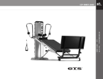
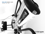
800 541 4900
®
EFISPORTSMEDICINE.COM
TOTAL GYM POWER TOWER
TM
®
OWNER’S GUIDE
TOTAL GYM POWER TOWER OWNER’S GUIDE
TM
CONGRATULATIONS
Thank you for purchasing Total Gym PowerTower™ . We welcome you as a
valued customer and trust your PowerTower will provide you with unsurpassed
convenience and versatility year after year.
®
Functional exercise equipment from efi Sports Medicine has set the standard for
physical rehabilitation, athletic training and sports performance training for more
than three decades.
Now, PowerTower adds the dynamic dimension of electrical power.
It allows:
• Unrestricted movement through all three planes of motion
In this Guide you will find tips about PowerTower and its
component parts, operation, maintenance and care. Additionally,
you will find safety tips and precautions to help ensure your
safety and the safety of your patients and clients. Your Guide also
includes warranty information. Please save this Owner's Guide and
refer to it in the future.
If you have any questions about PowerTower or if you need service,
please contact us. Our goal is to provide you with the premier
training tool for functional exercise, and we stand ready to assist
you every step of the way.
Sincerely,
• Proprioceptive training in every movement
• Recruitment of the core automatically
• Unloaded, early closed-chain exercise in a functional environment
• Calibrated, incremental increases and decreases in load
Tom Campanaro,
President/CEO
PowerTower enables you to fine-tune clients’ exercise regimens. Resistance is
adjustable during an exercise in progress with the press of a switch. The client
remains on the glideboard as you raise or lower the level of resistance.
efi Sports Medicine
7755 Arjons Drive
San Diego, CA 92126
As a result, your clients experience fewer transitions and more cohesive exercise
sessions. Plus, adjusting the resistance level is effortless.
U.S.A. area code (858) 586-6080
800 541 4900 toll-free inside U.S.A.
[email protected]
©2005, efi Corporation.
Your PowerTower arrives with very little required in the way of assembly. Simply
follow this Guide and in minutes your PowerTower will be operational.
CAUTION: As with any exercise program, participants should consult a physician before starting a workout on PowerTower. Changes or modifications to this PowerTower may void the
warranty and may violate U.S. Federal Communications Commission (FCC) Rules. Weight Capacity: PowerTower is rated at a maximum user weight capacity of 350 lbs [160 kg].
Additional weights with a weight bar can be applied to the glideboard. Do not exceed 650 lbs [295 kg] of weight-bearing on the PowerTower.
TOTAL GYM POWER TOWER OWNER’S GUIDE
®
TM
TOTAL GYM POWER TOWER OWNER’S GUIDE
®
TM
TABLE OF CONTENTS
Parts Identifier..............................................................................................................................................................................................2
Box and Hardware Packet Contents ..............................................................................................................................................................3
Warnings ..............................................................................................................................................................................................................4
Adjusting LAT Bars......................................................................................................................................................................................14
Folding Platform ........................................................................................................................................................................................15
Telescoping Squat Stand ............................................................................................................................................................................16
Pulley Locator Brackets ..............................................................................................................................................................................16
Rail Lock & Screw (optional) ......................................................................................................................................................................16
Folding Foot Holder ....................................................................................................................................................................................17
Adjusting the Rail Handle ..........................................................................................................................................................................18
Folding and Storage ..............................................................................................................................................................................19-22
Getting Started......................................................................................................................................................................................23-24
Safety Precautions ......................................................................................................................................................................................25
Troubleshooting ..........................................................................................................................................................................................26
Maintenance and Care................................................................................................................................................................................27
Reading Resistance Chart ..........................................................................................................................................................................27
Resistance Chart ........................................................................................................................................................................................28
Warranty Information ..................................................................................................................................................................................29
1
EFISPORTSMEDICINE.COM
Installing LAT Bars ..................................................................................................................................................................................9-13
800 541 4900
Parts Assembly..........................................................................................................................................................................................7-8
®
Specifications ..............................................................................................................................................................................................6
TOTAL GYM POWER TOWER
FCC Rules ..............................................................................................................................................................................................................6
OWNER’S GUIDE
Grounding Instructions ................................................................................................................................................................................5
TM
Fuse Replacement ........................................................................................................................................................................................4
PARTS IDENTIFIER - POWER TOWER
TM
ZY (see INSET 8)
^
^
ZX (see INSET 8)
INSET 1.
A
Z
^
B
C (see INSET 1)
Y (see INSET 7)
^
D
E (see INSET 2)
X
When parts are referenced
throughout this guide,
corresponding letters from
this PARTS IDENTIFIER page
are also listed. For example,
when “Tower” appears within
this guide, (A) will appear
behind “Tower” as a cue to refer
back to this page if needed.
E1
C
E2
INSET 3.
INSET 4. (SIDE VIEW)
R
F
G
^
^
^
F (see INSET 3)
W (on back of Tower; see INSET 6)
INSET 2.
V (on back of Rail; see INSET 6)
H
INSET 5. (BACK SIDE VIEW)
INSET 6.
V
T
U
S
^ ^ ^
^
O
T (on back of Tower; see INSET 5)
S (on back of Tower; see INSET 5)
R (on back of Tower; see INSET 4)
INSET 7. (SIDE VIEW)
M L
N
Q
INSET 8. (BACK TOP VIEW)
ZY
ZX
K
I
P
2
W
Y
J
^
A. Tower
E2. Lower Foot Pad Assembly
L. Glideboard Wheel Housing
S. Power Cord
Z. Tower Slot
B. Lateral Adjustable Training
(LAT) bars
F. Glideboard “D” Ring
M. Support Strut Knob
T. On/Off Switch
ZX. Safety Key
G. Glideboard
N. Support Strut
U. Handles
ZY. Up/Down Switch
C. Pulley Locator Brackets
H. Telescoping Squat Stand
O. Emergency Stop Touchpad
V. Rail Lock
D. Dynamic Arm Pulley System
I. Folding Platform
P. Tower Base
W. Center Rail Crossbar
E. Folding Foot Holder
J. Lower Rail Base
Q. Transport Wheels
X. Upper Rails
E1. Upper Foot Pad Assembly
K. Lower Rails
R. Electric DC Motor
Y. Tower Crossbar
TOTAL GYM POWER TOWER OWNER’S GUIDE
®
TM
PARTS ASSEMBLY - POWER TOWER
TM
Your PowerTowerTM arrives with some assembly required. Enclosed in your PowerTowerTM boxes you will find:
BB. LAT Bars & Arm Pulley
Cable Assembly
BOX CONTENTS
CC. Folding Platform
DD. Telescoping Squat Stand
HARDWARE PACKET CONTENTS
GG. Wrenches (2)
HH. Bronze Washers (4)
II. Chrome Washers (2)
JJ. Socket Head Screws (2)
KK. Rail Lock Screw (1)
Wrench handle
is a hex key.
LL. Quick Links (2)
MM. PowerTower Owner’s Guide (1)
NN. Handles (2)
OO. Safety Key (1)
3
EFISPORTSMEDICINE.COM
FF. One Hardware Packet Box
OWNER’S GUIDE
EE. Empty Spacer Box
800 541 4900
®
TOTAL GYM POWER TOWER
TM
AA. Tower, Rail &
Glideboard Assembly
NOTE: Letters in (parentheses) refer to the PARTS IDENTIFIER on page 2 and/or the PARTS ASSEMBLY on page 3. Use as needed for clarification.
IMPORTANT INFORMATION ABOUT YOUR
POWER TOWERTM
Your PowerTowerTM is an electrically powered
device. When using an electrical appliance,
basic precautions should always be followed,
including the following:
READ ALL INSTRUCTIONS BEFORE USING
THE POWER TOWER
DANGER – to reduce the risk of electric shock,
always unplug the PowerTower from the
electrical outlet immediately after using and
before cleaning.
WARNING – To reduce the risk of burns, fire,
electric shock, or injury to persons:
1. Inspect the PowerTower before each use
to ensure proper operation. Do not use
this equipment unless all moving parts
are working properly.
2. The PowerTower should never be left
unattended when plugged in. Unplug
from outlet when not in use, and before
putting on or taking off parts.
3. Keep the area near the base of the
Tower (A) clear to allow air flow into the
motor. Keep towels, blankets or loose
clothing off and clear of PowerTower and
its surrounding area. Keep all openings
free of lint, hair, and the like.
4. Close supervision is necessary when this
equipment is used by, on, or near
children, invalids, disabled or injured
persons.
4
5. Care should be taken at all times when
getting on and off the PowerTower or any
exercise equipment. Falling on or off the
product could result in injury, or
possibly death.
6. Use the PowerTower only for its intended
use. Do not use attachments not
recommended by the manufacturer.
7. Never operate the PowerTower if it has a
damaged Power Cord (S) or plug, if it is
not working properly, emits an odor or
unusual noise, if it has been dropped or
damaged, or dropped into water. Contact
the manufacturer for examination and
repair.
8. Do not pull the PowerTower by the Power
Cord (S) or use the Power Cord (S) as a
handle.
9. Keep the Power Cord (S) away from heated
surfaces.
10. Place the PowerTower on a flat level
surface. Allow ample clearance for the
Rails (K, X) to lower to their fully extended
position. Do not store anything under
the PowerTower.
11. Never drop or insert any object, including
fingers, into any PowerTower opening.
12. Do not use the PowerTower outdoors.
13. Do not operate where aerosol (spray)
products are being used or where oxygen
is being administered.
14. To disconnect, turn all controls to the OFF
position, then remove plug from outlet.
15. Keep fingers, loose clothing, and hair
away from moving parts.
FUSE REPLACEMENT
To replace 5A Fuse in Tower (A) back:
- Unplug the Power Cord (S) from the
power outlet.
- Locate the fuse assembly near the power
outlet on the Tower (A).
- Use a flathead screwdriver to pull out
the fuse assembly.
- There are (2) 5A fuses in the fuse assembly.
One is a spare.
- The other is in use (Fig. 1).
- Remove the old fuse from the clamp.
- Push the old fuse far enough into the hole of
the fuse assembly to release the spare fuse
(Fig. 2).
- Place the spare fuse into clamp (Fig. 3).
- Dispose of the old fuse. Replace the
fuse assembly.
Figure 1
Figure 2
Figure 3
TOTAL GYM POWER TOWER OWNER’S GUIDE
®
NOTE: Letters in (parentheses) refer to the PARTS IDENTIFIER on page 2 and/or the PARTS ASSEMBLY on page 3. Use as needed for clarification.
DANGER - Improper connection of the equipmentgrounding conductor can result in a risk of electric
shock. Check with a qualified electrician or
serviceman if you are in doubt as to whether the
product is properly grounded. Do not modify the plug
provided with the product – if it will not fit the outlet,
have a proper outlet installed by a qualified electrician.
A PowerTower that is for use on a nominal 120-volt
circuit has a grounding plug that looks like the plug
illustrated in Figure 1. A temporary adapter that looks
like the adapter illustrated in Figure 2 may be used
to connect this plug to a 2-pole receptacle as shown
in Figure 2 if a properly grounded outlet is not
available. The temporary adapter should be used
only until a properly grounded outlet (Figure 1) can
be installed by a qualified electrician. The green
colored rigid ear, lug, or the like extending from the
adapter must be connected to a permanent ground
such as a properly grounded outlet box cover.
Whenever the adapter is used, it must be held in
place by a metal screw.
5
EFISPORTSMEDICINE.COM
TM
The PowerTower is equipped with a Power Cord (S)
having an equipment-grounding conductor and a
grounding plug. The plug must be plugged into an
appropriate outlet that is properly installed and
grounded in accordance with all local codes
and ordinances.
Depending on your country of residence, you can
purchase a 120 VAC or 230 VAC PowerTower.
Some adapters may be permitted, similar to the type
explained below:
®
FOLLOW THESE GROUNDING INSTRUCTIONS
The PowerTower must be grounded. If it should
malfunction or break down, grounding provides a
path of least resistance for electric current to reduce
the risk of electric shock.
800 541 4900
See grounding instructions.
Figure 2
TOTAL GYM POWER TOWER
WARNING: Connect the
PowerTowerTM to a properly
grounded outlet only. Improper
connection of the equipment
grounding connector can result
in the risk of electric shock. Do
not modify the plug that is
provided with the PowerTower. If
it will not fit in the outlet, have
a proper outlet installed by a
qualified electrician.
Figure 1
OWNER’S GUIDE
IMPORTANT NOTICE ABOUT
PROPER GROUNDING
TM
NOTE: Letters in (parentheses) refer to the PARTS IDENTIFIER on page 2 and/or the PARTS ASSEMBLY on page 3. Use as needed for clarification.
FCC RULES
Warning: Changes or modifications to this unit not expressly approved by
the party responsible for compliance could void the user’s authority to
operate the equipment.
SPECIFICATIONS
Power:
115 Volts and 5 Amps or
230 Volts and 3 Amps
50 or 60 cycles depending on the country where it is sold.
NOTE: This equipment has been tested and found to comply with the limits
for a Class B digital device, pursuant to Part 15 of the FCC Rules. These
limits are designed to provide reasonable protection against harmful
interference in a residential installation. This equipment generates, uses
and can radiate radio frequency energy and, if not installed and used in
accordance with the instructions, may cause harmful interference to
radio communications.
Incline Speed:
Approximately 30 seconds to ascend/
20 seconds to descend. (Varies under load)
However, there is no guarantee that interference will not occur in a
particular installation. If this equipment does cause harmful interference
to radio or television reception, which can be determined by turning the
equipment off and on, the user is encouraged to try to correct the
interference by one or more of the following measures:
- Reorient or relocate the receiving antenna.
- Increase the separation between the equipment and receiver.
- Connect the equipment into an outlet on a circuit different from
that to which the receiver is needed.
Consult the dealer or an experienced radio/TV technician for help.
Dimensions:
Standing: 110” x 36” x 76” [L/W/H]
(2.5 m x .9 m x 1.9 m)
Folded: 24” x 36” x 63” [L/W/H]
(.6 m x .9 m 1.5 m)
Resistance:
• 4° to 34° increments are marked.
• 11 levels of calibration at 3° increments
appear on the Resistance Chart (see page 28).
• 3% to 72% of body weight
User Height Limit:
6’5” (2.0 m)
Weight Capacity:
PowerTowerTM is rated at a maximum user weight capacity of
350 lbs. [160 kg]. Additional weights can be applied to the
glideboard on a weight bar, up to 650 lb [295 kg] maximum total.
FCC ID: UHJPOWERTOWER
6
ETL #3100548
TOTAL GYM POWER TOWER OWNER’S GUIDE
®
NOTE: Letters in (parentheses) refer to the PARTS IDENTIFIER on page 2 and/or the PARTS ASSEMBLY on page 3. Use as needed for clarification.
PARTS ASSEMBLY
TM
1
3.
While unfolding the PowerTower, as an extra precaution, hold the side of the Tower (A)
with one hand to steady the Tower (A).
4.
With the other hand, push the Lower Rails (K) off and away from the Tower Base (P)
by grasping the padded Center Rail Crossbar (W)and allow the Rails (K, X) to unfold
slowly away from the Tower (A) until the Rails (K, X) are fully extended.
CAUTION: Do not touch the hinge.
2
3
4
7
EFISPORTSMEDICINE.COM
POWER TOWER SET-UP
800 541 4900
Pull and twist the retractable Support Strut Knob (M) to loosen it.
®
2.
TOTAL GYM POWER TOWER
To begin assembly, remove your PowerTowerTM from the box. Stand the PowerTower upright.
Find Hardware Packet (see page 3 for Hardware Packet Contents).
OWNER’S GUIDE
1.
TM
PUTTING YOUR POWER TOWERTM INTO OPERATION IS EASY.
NOTE: Letters in (parentheses) refer to the PARTS IDENTIFIER on page 2 and/or the PARTS ASSEMBLY on page 3. Use as needed for clarification.
53
9
PARTS ASSEMBLY (CONTINUED)
5.
Engage and tighten the Support Strut Knob (M). You need to lean
the tower backward slightly to engage the pin.
IMPORTANT SAFETY NOTICE: The Support Strut Knob (M) must be
engaged and tightened during PowerTowerTM use.
6
Lift
8
8
Remove the packing foam from the four wheels. To reposition the
Glideboard (G) for use, kneel beside the Glideboard (G). Lift and
pull one side of the metal Glideboard Wheel Housings (L) away
from the Rails (K, X).
7.
Lift the opposite side of the Glideboard (G) until the wheels lift
completely off the Rails (K, X).
8.
Move the Glideboard (G) about 6 inches up the Rails (K, X)
toward the Tower (A), until the metal stop on the underside of
the Glideboard (G) rests above the rubber bumper. Lower the
Glideboard (G) and pull the Glideboard Wheel Housings (L) out
as you lower the Glideboard (G) back into place.
9.
Connect the Power Cord (S) to the back of the PowerTower.
Then connect the PowerTower to an appropriate receptacle.
10.
Turn on the PowerTower with the On/Off Switch (T) at the bottom
back of the Tower (A).
11.
Remove the Safety Key (ZX) from the Hardware Packet. Use the
loop in the Safety Key (ZX) lanyard to tie it to the Tower’s (A)
back handle. Insert the Safety Key (ZX) into the hole on top of
the Tower (A). Your PowerTower will not operate if the Safety Key
(ZX) is not in place.
12.
Raise the Rails (K, X) to the desired level by using the Up/Down
Switch (ZY) on top of the Tower (A).
10
Pull
7
6.
11
12
TOTAL GYM POWER TOWER OWNER’S GUIDE
14.
Ensure that the Support Strut Knob (M) is engaged and tight.
REMOVE THE SHIPPING SLEEVES - PHASE 1
15. Your PowerTowerTM arrives with shipping sleeves on the ends of the Tower Crossbar (Y).
The shipping sleeves serve one purpose: to protect the Tower Crossbar (Y) during shipping.
NOTE: For easiest assembly, keep the Tower Crossbar (Y) centered throughout the assembly
process, with each end extending about equal distance from the Tower (A).
®
HARDWARE PACKET TOOLS NEEDED: To remove the first shipping sleeve, face the Tower (A)
back and take one of the supplied Wrenches (GG) in each hand. The Wrenches (GG)are
located in the Hardware Packet (contents shown on page 3).
15
OWNER’S GUIDE
16.
14
16
9
EFISPORTSMEDICINE.COM
Raise the Rails (K, X) to Tower (A) to 20 degrees for ease of assembly, as shown.
800 541 4900
13.
13
TM
INSTALLING LAT BARS
TM
TOTAL GYM POWER TOWER
®
NOTE: Letters in (parentheses) refer to the PARTS IDENTIFIER on page 2 and/or the PARTS ASSEMBLY on page 3. Use as needed for clarification.
NOTE: Letters in (parentheses) refer to the PARTS IDENTIFIER on page 2 and/or the PARTS ASSEMBLY on page 3. Use as needed for clarification.
17
INSTALLING LAT BARS (CONTINUED)
17.
Apply one Wrench (GG) to the nyloc nut on one side of the Tower Crossbar (Y). Use the
other Wrench (GG) to loosen the nyloc nut on the other side of the Tower Crossbar (Y) by
turning counterclockwise. Set the shipping sleeve aside.
18.
Remove the nyloc nut, Chrome Washer (II) and the Bronze Washer (HH). Set them aside.
19.
Lift the Upper Rail (X) with one hand. Remove the first shipping sleeve from the
Tower Crossbar (Y) with the other hand.
20.
To remove the remaining shipping sleeve, immobilize the exposed end of the
Tower Crossbar (Y) by applying one of the Wrenches (GG) to the notch.
18
19
20
10
TOTAL GYM POWER TOWER OWNER’S GUIDE
22.
Hold the Upper Rail (X) with one hand. Remove the shipping sleeve from the Tower
Crossbar (Y) with the other hand. Set the shipping sleeve aside.
Now that the shipping sleeves have been removed, you are ready to attach the first
LAT Bar (B). You may discard the shipping sleeves or retain them in the event you need
to ship your PowerTowerTM in the future.
23
24.
Slide a Bronze Washer (HH) onto the LAT Bar (B) cylinder. Stand beside the Tower (A) and
align the LAT Bar (B) cylinder with the Tower Crossbar (Y).
®
POSITIONING THE LAT BARS - PHASE 2
23. To position the first LAT Bar (B) for mounting, make sure the long, vertical side of the
LAT Bar (B) aligns closest to the Tower (A). (The slotted holes face the back of the
PowerTower, the black knob on the LAT Bar (B) faces the Glideboard (G).)
24
25.
OWNER’S GUIDE
REMINDER: Keep the Tower Crossbar (Y) centered during assembly.
Slide the LAT Bar (B) cylinder onto the Tower Crossbar (Y) until it is securely seated on the
Upper Rail (X).
HINT: You will need to lift the Upper Rail (X) to slide the LAT Bar (B) cylinder inside the hole
in the Upper Rail (X).
25
11
EFISPORTSMEDICINE.COM
Use the other Wrench (GG) to loosen the remaining nyloc nut by turning it counterclockwise.
22
800 541 4900
21.
21
TM
INSTALLING LAT BARS (CONTINUED)
TM
TOTAL GYM POWER TOWER
®
NOTE: Letters in (parentheses) refer to the PARTS IDENTIFIER on page 2 and/or the PARTS ASSEMBLY on page 3. Use as needed for clarification.
NOTE: Letters in (parentheses) refer to the PARTS IDENTIFIER on page 2 and/or the PARTS ASSEMBLY on page 3. Use as needed for clarification.
26
INSTALLING LAT BARS: POSITIONING THE LAT BARS - PHASE 2 (CONTINUED)
26.
Rotate the LAT Bar (B) upside-down until the other LAT Bar (B) is installed, and both nyloc nuts
on the Tower Crossbar (Y) have been tightened.
27.
Return the Chrome Washer (II) to the end of the Tower Crossbar (Y) that extends beyond the
LAT Bar (B) cylinder.
Attach and finger tighten the nyloc nut onto the Tower Crossbar (Y) with the other hand.
27
28.
Press against the nyloc nut to push the Tower Crossbar (Y) until it lies flush against the
LAT Bar (B) cylinder. This will help seat the LAT Bar (B) against the Upper Rail (X).
Repeat Phase 2 for the other LAT Bar (B). Tighten both LAT Bars (B) with the Wrenches (GG)
until the nyloc nuts get hard to turn (no threads should be showing).
28
29
12
ATTACHING THE LAT BAR BRACKET - PHASE 3
29. Remove the remaining contents (shown on page 3)from your Hardware Packet. Lower the
LAT Bar (B) to the Pull-up position.
TOTAL GYM POWER TOWER OWNER’S GUIDE
®
NOTE: Letters in (parentheses) refer to the PARTS IDENTIFIER on page 2 and/or the PARTS ASSEMBLY on page 3. Use as needed for clarification.
INSTALLING LAT BARS: ATTACHING THE LAT BAR BRACKET - PHASE 3 (CONTINUED)
30.
Place a Chrome Washer (II) followed by a Bronze Washer (HH) on a Socket Head Screw (JJ).
31.
Feed the Socket Head Screw (JJ) partially through the elongated slot.
TM
30
Attach the Handles (U) to the ends of the Dynamic Arm Pulley System (D) using the
Quick Links (LL).
32
With these steps completed, your LAT Bars (B) are assembled.
OWNER’S GUIDE
33.
®
Repeat Phase 3 (Attaching the Lat Bar Bracket) on the opposite side.
33
13
EFISPORTSMEDICINE.COM
Tighten the Socket Head Screw (JJ) with the hex end handle of the Wrench (GG).
800 541 4900
32.
31
TOTAL GYM POWER TOWER
Thread the Socket Head Screw (JJ) into the hole in the rail. Align the Socket Head Screw (JJ)
with the hole in the Upper Rail (X) inside the LAT Bar (B) bracket. Finger tighten the Socket
Head Screw (JJ)
TM
Place another Bronze Washer (HH) on the Socket Head Screw (JJ) on the other side of
the bracket.
NOTE: Letters in (parentheses) refer to the PARTS IDENTIFIER on page 2 and/or the PARTS ASSEMBLY on page 3. Use as needed for clarification.
ADJUSTING THE LAT BARS
34
34.
Knob
35
36
37
14
To adjust the LAT Bars (B), pull the retractable knob on the LAT Bar to disengage the Lat Bar
from the Upper Rail (X) and rotate LAT Bars to the desired position. Ensure that the pin on the
retractable knob is properly engaged.
LAT BAR ADJUSTS TO THREE POSITIONS
35.
NORMAL USE: parallel (upright) to the Tower (A), perpendicular to Rails (K,X)
36.
PULL-UP POSITION: angled upwards from the Rails (K,X)
37.
FOLD UP POSITION: parallel to the Rails (K,X)
TOTAL GYM POWER TOWER OWNER’S GUIDE
40.
Pull the retractable pin on the right side and move the pin over the hole. Release the pin.
41.
Move the Folding Platform (H) until all the pins engage completely.
39
40
41
15
EFISPORTSMEDICINE.COM
Using the two holes just above the Lower Rail Base (J), slide the fixed pin into the hole
in the outside left Lower Rail as you face the Tower (A).
800 541 4900
39.
TM
Align the bottom of the Folding Platform (H) with the Lower Rails (K) just above the
Lower Rail Base (J).
®
38.
38
TOTAL GYM POWER TOWER
FOLDING PLATFORM
TM
OWNER’S GUIDE
®
NOTE: Letters in (parentheses) refer to the PARTS IDENTIFIER on page 2 and/or the PARTS ASSEMBLY on page 3. Use as needed for clarification.
NOTE: Letters in (parentheses) refer to the PARTS IDENTIFIER on page 2 and/or the PARTS ASSEMBLY on page 3. Use as needed for clarification.
TELESCOPING SQUAT STAND
42
43
42.
Align the Telescoping Squat Stand (H) over the Folding Platform (I) struts until the
Telescoping Squat Stand (H) pins contact the top of the Folding Platform (I) struts.
43.
Pull the retractable pins and adjust the Telescoping Squat Stand (H) to the desired height,
then release the pins and raise or lower the Telescoping Squat Stand (H) until both pins
engage in one of the three adjustment holes in the Folding Platform (I) struts.
PULLEY LOCATOR BRACKETS
44.
The Pulley Locator Brackets (C) are designed to adjust easily. Pull back on the pin, move the
Pulley Locator Bracket (C) to the desired position on the LAT Bars (B) and allow the pin to
engage the slotted hole. You should rotate the pulley toward the center of the LAT Bar as
shown when moving the Pulley Locator Bracket (C) around the bends.
RAIL LOCK & SCREW (OPTIONAL)
44
45.
45
Rail Lock
Rail Lock Screw
16
If you intend to use your PowerTowerTM to do plyometrics at high inclines, and you do not intend
to fold the PowerTower for storage often, you may wish to use this rail lock feature. Unfold the
PowerTower, sit on the Glideboard (G), and screw in the long Rail Lock Screw (KK) (provided in
the Hardware Packet) finger tight in to the Rail Lock (V). To remove it for storage, reverse the
process.
TOTAL GYM POWER TOWER OWNER’S GUIDE
48.
To begin using the Folding Foot Holder (E), push in the center post snap button and raise the
Upper Foot Pad Assembly (E1).
49.
Sit at the top of the Glideboard (G) and place your heels past the pads of the Lower Root Pad
Assembly (E2). Lower the Upper Foot Pad Assembly (E1) by pushing it down until the center
post snap button has re-engaged.
NOTE: Remember to return the Folding Foot Holder (E) to its original “lowered” position to avoid
interference with the Glideboard (G) during other exercises.
47
48
49
17
EFISPORTSMEDICINE.COM
Prior to use, rotate the Folding Foot Holder (E) to the upright position. Simply pull on the
retractable knob and raise the Folding Foot Holder (E) until the pin on the knob has engaged
the Upper Rail (X). Be sure the Folding Foot Holder (E) is securely mounted in the upright
position before proceeding.
800 541 4900
47.
TM
Your PowerTowerTM arrives with the Folding Foot Holder (E) in the down position.
®
46.
46
TOTAL GYM POWER TOWER
FOLDING FOOT HOLDER
TM
OWNER’S GUIDE
®
NOTE: Letters in (parentheses) refer to the PARTS IDENTIFIER on page 2 and/or the PARTS ASSEMBLY on page 3. Use as needed for clarification.
NOTE: Letters in (parentheses) refer to the PARTS IDENTIFIER on page 2 and/or the PARTS ASSEMBLY on page 3. Use as needed for clarification.
50
51
52
18
ADJUSTING THE RAIL ANGLE
50.
To raise or lower the Rail (K, X) angle, stand alongside the Tower (A). Reach on top of the
Tower (A) to the Up/Down Switch (ZY). Micro switches at the upper and lower ranges of
resistance (4 degrees and 34 degrees respectively) halt movement at upper and lower
resistance limits. Any time you release the Up/Down Switch (ZY), movement ceases.
51.
Any time you wish to use the glideboard free from the pulley cable assembly, simply unfasten
and release the center cable pulley snap hook.
52.
Snap the center cable pulley to one of the LAT Bar pulley Locator brackets as shown.
TOTAL GYM POWER TOWER OWNER’S GUIDE
®
NOTE: Letters in (parentheses) refer to the PARTS IDENTIFIER on page 2 and/or the PARTS ASSEMBLY on page 3. Use as needed for clarification.
TM
FOLDING AND STORAGE
53
5
1
6
56
57
58
19
EFISPORTSMEDICINE.COM
2
55
800 541 4900
57-58. Lower the LAT Bars (B) into the folding position - parallel to Rails (K, X).
4
®
Pull the retractable knob on the LAT Bars (B).
54
3
TOTAL GYM POWER TOWER
56.
LAT Bar Positions
OWNER’S GUIDE
54-55. Position the Pulley Locator Brackets (C) at the fourth position on the LAT Bars (B).
TM
FOR STORAGE, POWERTOWER FOLDS EASILY.
Press the Up/Down Switch (ZY) to raise or lower the Rails (K, X). Stop about halfway up the
53.
Tower (A). Remove the Rail Lock Screw (KK) if it has been installed. HINT: Sit on the
Glideboard (A) and remove the Rail Lock Screw (KK) from the Rail Lock (V) if it has been
installed.
NOTE: Letters in (parentheses) refer to the PARTS IDENTIFIER on page 2 and/or the PARTS ASSEMBLY on page 3. Use as needed for clarification.
FOLDING AND STORAGE (CONTINUED)
59
59.
Attach the center pulley to the Glideboard “D” Ring (F).
60.
Lower the Folding Foot Holder (E) to the down position.
61-62. Fold the Folding Platform (I) and Telescoping Squat Stand (H). Pull the left side (as you face
the Tower (A)) retractable pin, while pushing the Telescoping Squat Stand (H) forward until
the retractable pin locks in place in the folded position.
60
61
62
20
TOTAL GYM POWER TOWER OWNER’S GUIDE
®
TM
FOLDING AND STORAGE (CONTINUED)
The Tower (A) will lean backward slightly.
65.
Release the Support Strut Knob (M) by unscrewing the knob and pulling it out.
HINT: Gently rock the Tower (A) backward to help release tension on the Support Strut Knob (M)
then pull it forward to the vertical position.
64
IMPORTANT: Failure to release Support Strut Knob (M) can damage your PowerTowerTM.
®
Hold the Tower (A) while grasping the padded Center Rail Crossbar (W). Pull the Rails (K, X)
up and toward the Tower (A).
65
OWNER’S GUIDE
66.
66
hold
21
EFISPORTSMEDICINE.COM
64.
800 541 4900
Press the Up/Down Switch (ZY) until the Rails (K, X) descend to the lowest possible position
and automatically stop.
TM
63.
63
TOTAL GYM POWER TOWER
NOTE: Letters in (parentheses) refer to the PARTS IDENTIFIER on page 2 and/or the PARTS ASSEMBLY on page 3. Use as needed for clarification.
NOTE: Letters in (parentheses) refer to the PARTS IDENTIFIER on page 2 and/or the PARTS ASSEMBLY on page 3. Use as needed for clarification.
67
69
68
FOLDING AND STORAGE (CONTINUED)
67.
Pull the rails into A-frame position, making sure the Support Strut Knob (M) remains
disengaged.
68.
Push the Rails (K, X) and the Tower (A) together. Stand the Lower Rail Base (J) on the
Tower Base (P).
IMPORTANT NOTES:
69.
When storing your PowerTowerTM, hang the Handles (U) out of the way, making sure that
Dynamic Arm Pulley System (D) cables remain free from contact with hinges, the floor,
or wheels.
To move the PowerTower, stand behind the Tower (A), grasp the Tower (A) top, pull back in
hand truck fashion and roll. To unfold PowerTower and return it to use, see the beginning of
these instructions.
70
NOTE: Be sure to secure the Handles (U) away from the Tower Base (P) and Transport Wheels (Q)
before moving.
OPTIONAL ACCESSORY
71
70.
WEIGHT BAR
71.
The Weight Bar lets you add standard plate weights to the PowerTower to achieve greater
resistance.
Observe the instructions provided with each accessory.
22
TOTAL GYM POWER TOWER OWNER’S GUIDE
®
NOTE: Letters in (parentheses) refer to the PARTS IDENTIFIER on page 2 and/or the PARTS ASSEMBLY on page 3. Use as needed for clarification.
GETTING STARTED
TM
72
When using PowerTowerTM, wear athletic shoes and comfortable lightweight clothing. Tie long
hair back to avoid contact with the center pulley. Before you begin, check to ensure that all
parts are in place and working properly.
73.
Pull the Glideboard (G) up the Rails (K, X) to the height needed to sit in the proper position for
the specific exercise you will perform.
74.
EXAMPLE: If you are performing a sitting exercise, sit at the top of the Glideboard (G).
75.
If the exercise requires you to lie back, first sit at the bottom of the Glideboard (G) with one
Dynamic Arm Pulley System (D) Handle (U) in each hand.
74
75
23
EFISPORTSMEDICINE.COM
Grasp both Handles (U) in the hand closest to the Tower (A) as you stand to one side of the
PowerTower.
OWNER’S GUIDE
72.
®
PROPER FORWARD ANCHORING SEQUENCE WITH ARM PULLEY SYSTEM ATTACHED TO THE GLIDEBOARD
800 541 4900
73
TOTAL GYM POWER TOWER
Remember to control the Glideboard (G) at all times, particularly when getting on or off your
PowerTower. The following tips will help you stabilize the Glideboard (G) as you approach the unit for
mounting in various positions. Use these mounting concepts when teaching patients to get on and off
the unit.
TM
Begin your exercise program at a low incline. As your proficiency increases, raise the incline
to increase the intensity.
NOTE: Letters in (parentheses) refer to the PARTS IDENTIFIER on page 2 and/or the PARTS ASSEMBLY on page 3. Use as needed for clarification.
76
76.
When lying on your back, be sure your head is supported on the Glideboard (G). If the
Glideboard (G) travels all the way to the top or bottom of its rolling distance during the
exercise, adjust your body up or down on the Glideboard (G).
PROPER BACKWARD ANCHORING SEQUENCE WITH DYNAMIC ARM PULLEY SYSTEM (D)
ATTACHED TO GLIDEBOARD (G)
77.
Grasp Handles (U), then make a fist and place your knuckles at the top of the Glideboard (G) to
anchor it in place. Now it is safe to sit, straddle or kneel on the Glideboard (G).
78.
When kneeling on the Glideboard (G), place knees one at a time just behind your fists
as you face the Glideboard (G).
79.
Move to the starting position of the exercise and begin by using slow, controlled movements.
77
!
78
79
24
WARNING
Always control the Glideboard (G) while mounting or dismounting your PowerTower TM. PowerTower is rated at a
maximum user weight capacity of 350 lbs [160 kg] . Additional weights can be applied with a weight bar to
the Glideboard (G). Do not exceed 650 lb [295 kg] of weight-bearing on the PowerTower.
TOTAL GYM POWER TOWER OWNER’S GUIDE
Inspect your PowerTower before each use to
ensure proper operation. Check all parts for
wear before each use. Do not use your
PowerTower if it is not completely assembled
or has been damaged in any manner. Contact
efi Sports Medicine Customer Service for
replacement parts or repairs.
!
Follow the instructions that are outlined in this
Owner’s Guide for operating your PowerTower.
WARNING
Failure to read and follow the safety instructions in this manual may result in serious injury or death. Hazards include
falling, overexertion, strained muscles, pinched fingers or pulled hair. Changes or modifications to this PowerTower
may void the warranty and may violate U.S. Federal Communications Commission (FCC) Rules.
25
EFISPORTSMEDICINE.COM
PowerTower is rated at a maximum user weight
capacity of 350 lbs [160 kg]. Additional
weights can be applied to the glideboard with a
weight bar, up to 650 lb [295 kg] maximum total.
TM
Keep fingers, loose clothing and hair away from
moving parts. Wear appropriate exercise attire
and tie long hair back.
Follow instructions in this Owner’s Guide when
getting on and off the unit. Falling on or off
could result in severe or fatal injury.
Place your PowerTower on a flat, solid surface
with nonskid material underneath. Keep the
rail base free from obstructions.
800 541 4900
Do not over exert with this or any exercise
program. If any pain or tightness in the chest
is experienced, or an irregular heartbeat,
shortness of breath, or faintness, nausea or
dizziness, stop exercising immediately and
consult your physician before resuming any
exercise program. (Clinicians should follow
these recommendations if these symptoms
are observed in patients.)
Use only accessory items recommended by the
manufacturer. Only use accessories in the
manner specified by the manufacturer.
®
Before starting this or any exercise program,
consult your physician, who can assist in
planning a program that is age and ability
specific. Certain exercise programs or types
of equipment may not be appropriate for
all people.
This product is designed and intended for
commercial use. Clinicians should inform
patients of and monitor their adherence to all
safety precautions. Use only as instructed.
Do not permit anyone to stand on the
PowerTowerTM or use it as furniture. Children
should only use the PowerTower when closely
attended and supervised by an adult. Do not
leave children or patients unattended on the
PowerTower.
TOTAL GYM POWER TOWER
SAFETY PRECAUTIONS
TM
OWNER’S GUIDE
®
NOTE: Letters in (parentheses) refer to the PARTS IDENTIFIER on page 2 and/or the PARTS ASSEMBLY on page 3. Use as needed for clarification.
NOTE: Letters in (parentheses) refer to the PARTS IDENTIFIER on page 2 and/or the PARTS ASSEMBLY on page 3. Use as needed for clarification.
TROUBLESHOOTING
In the event your PowerTowerTM does not function properly, there are steps you can take to determine where a problem may have occurred.
Please follow these troubleshooting directions:
1. Power source. Make sure that the Power Cord (S) is plugged into the PowerTower and the wall. Check and determine that the plug on the wall
is switched on. If there is a ground fault interrupter, check to see if it has been tripped.
2. PowerTower Power Switch. Make sure that the On/Off Switch (T) on the Tower (A) has been turned on. The light should glow red to indicate
that the power is going into the PowerTower.
3. Fuse. If the red light indicator on the Tower’s (A) On/Off Switch (T) is not glowing, check the fuse located near the power outlet on the back of
the Tower (A). Follow 5A fuse replacement instructions in the IMPORTANT INFORMATION ABOUT YOUR POWER TOWERTM section (page 4) of this
guide.
4. Power Cord. Make sure the Power Cord (S) is not damaged. If Power Cord (S) appears damaged, go to Step 8 below and call Customer Service.
5. Support Strut. Make sure the Support Strut (N) is free of any objects that may have been placed on top of it. Handles (U), Dynamic Arm Pulley
System (D) cables and pulleys, Folding Foot Holder (E) or any other objects will engage a sensor on the Support Strut (N) and cause the Electric
DC Motor (R) to cease to operate.
6. Support Strut wires. If the wires that connect the Support Strut (N) to the Tower Base (P) have been damaged or broken, the PowerTower will
not operate. Go to Step 8 below and call Customer Service.
7. AC voltage. An interruption in the flow of voltage can cause the PowerTower to cease functioning. As an example, should the AC voltage drop
40%, the PowerTower Electric DC Motor (R) will cease to operate. After the supply of voltage has been fully restored, the user can reset the
machine by turning the On/Off Switch (T) off and then on again. The PowerTower will then resume functioning.
8. Safety Key. Make sure the Safety Key (ZX) is inserted into the connector hole located on top of the Tower (A). Your PowerTower will not operate
if the Safety Key (ZX) is not in place.
9. After troubleshooting. If there is still a problem after checking all of the above items, please call 800 541 4900 to speak to a
Customer Service Representative.
26
TOTAL GYM POWER TOWER OWNER’S GUIDE
®
Clean the Glideboard (G) material with a
non oil-based window cleaner. DO NOT use
Armor All® or like substances. These will
make the glideboard slippery. Wipe down
your PowerTower with a clean cloth.
Check and/or tighten the shoulder bolts in
the rails weekly.
RESISTANCE CHART
HOW TO READ THE RESISTANCE CHART
FOR POWER TOWERTM
(SEE NEXT PAGE TO VIEW CHART)
PowerTower uses a variable angle incline plane
to create exercise resistance by modifying the
user’s body weight—a steeper angle generates
more resistance. The Resistance Chart for
PowerTower is calculated to indicate the
resistance load at each level relative to a
percentage of body weight. Down the left side
of the chart, note the PowerTower levels 1-11.
Each level’s degree of slope is noted. Across
the top, the numbers represent body weight in
ten-pound increments. Below each weight
reference in pounds are two corresponding
columns. Each left column represents a
percentage of body weight. Each right column
shows the actual amount of load in pounds. An
additional Resistance Chart has also been
supplied with weight references in kilograms.
Example in kg: a 70 kg person using level 5
would be lifting 21 kilograms or 30% of total
body weight. When figuring exercises that
incorporate both Dynamic Arm Pulley System
(D) cables, use 50% of the charted numbers.
TM
would be lifting 45 pounds or 30% of total body
weight. When figuring exercises that incorporate
the bilateral pulley cables, use 50% of the
charted numbers.
27
EFISPORTSMEDICINE.COM
CAUTION: DO NOT use any lubricants or
silicone based products on the rails or rollers.
This will cause the rollers to slide rather than
roll, and will damage the rollers.
You may use lubricant on the bearings, folding
hinges and chains when needed. When
lubricating these parts, remove any residue
of lubricant from the cables, rails or roller
surfaces.
Replace all parts that show signs of wear.
Contact Customer Service at 800-541-4900.
Example in lbs: a 150 lb person using level 5
800 541 4900
Use chrome or car polish on all chrome parts
to keep your PowerTower looking its best and
to prevent dust build-up. Clean rail surfaces
on a regular basis with a non oil-based
window cleaner.
Power Cord (S) • Handles (U) • Dynamic Arm
Pulley System (D) Cables and Nylon Coating •
Pulleys • Rollers • Glideboard (G) • Folding
Platform (I) • Telescoping Squat Stand (H)
Frame • Tower (A) • Tower Base (P) • Up/Down
Switch (ZZ) • Foam Rubber Parts
PowerTower can be adjusted between marked
levels. NOTE: Chart is accurate within a 4%
margin of error.
®
Your PowerTowerTM will offer you or your
rehabilitation or wellness facility and your
clientele years of easy operation if you follow
these simple tips for maintenance and care.
With periodic cleaning, moving parts and
rolling surfaces will maintain their smooth
function.
Periodically check the following parts for signs
of fraying, cracking or wear:
TOTAL GYM POWER TOWER
MAINTENANCE AND CARE
TM
OWNER’S GUIDE
NOTE: Letters in (parentheses) refer to the PARTS IDENTIFIER on page 2 and/or the PARTS ASSEMBLY on page 3. Use as needed for clarification.
RESISTANCE CHARTS FOR TOTAL GYM POWER TOWERTM
BODY WT - Lbs. 100
110
120
LEVEL SLOPE % WT.
% WT.
% WT.
11
10
9
8
7
6
5
4
3
2
1
8
130
140
% WT. % WT.
150
160
% WT.
% WT.
170
180
190
% WT. % WT.
200
% WT. % WT.
210
220
230
240
250
260
% WT.
% WT.
% WT.
% WT.
% WT.
% WT.
270
%
WT.
280
%
290
WT. %
WT.
300
% WT.
310
%
WT.
320
%
WT. %
330
340
WT. %
WT.
350
%
WT.
34 69 69 68 75 67 81 66 86 66 92 65 97 64 103 64 108 63 114 63 120 63 125 62 131 62 136 62 142 62 148 61 153 61 159 61 164 61 170 61 176 60 181 60 187 60 192 60 198 60 204 60 209
31 64 64 63 69 62 74 61 79 60 84 60 90 59 95 59 100 58 105 58 110 58 115 57 121 57 126 57 131 57 136 56 141 56 146 56 151 56 157 56 162 56 167 55 172 55 177 55 182 55 187 55 193
28 58 58 57 63 56 68 56 72 55 77 54 82 54 86 54 91 53 96 53 100 53 105 52 110 52 115 52 119 52 124 51 129 51 133 51 138 51 143 51 147 51 152 51 157 50 161 50 166 50 171 50 176
25 52 52 51 57 51 61 50 65 50 69 49 74 49 78 48 82 48 86 48 90 47 95 47 99 47 103 47 107 46 112 46 116 46 120 46 124 46 128 46 133 46 137 46 141 45 145 45 150 45 154 45 158
22 46 46 46 50 45 54 44 58 44 61 43 65 43 69 43 73 42 76 42 80 42 84 42 88 42 91 41 95 41 99 41 103 41 106 41 110 41 114 41 118 40 121 40 125 40 129 40 133 40 136 40 140
19 40 40 40 44 39 47 39 50 38 53 38 57 37 60 37 63 37 66 37 70 36 73 36 76 36 79 36 83 36 86 36 89 36 92 35 96 35 99 35 102 35 105 35 109 35 112 35 115 35 119 35 122
16 34 34 34 37 33 40 33 42 32 45 32 48 32 51 31 53 31 56 31 59 31 62 31 64 31 67 30 70 30 73 30 76 30 78 30 81 30 84 30 87 30 89 30 92 30 95 30 98 30 100 29 103
13 28 28 27 30 27 32 27 35 26 37 26 39 26 41 26 44 25 46 25 48 25 50 25 53 25 55 25 57 25 59 25 62 25 64 24 66 24 68 24 71 24 73 24 75 24 77 24 80 24 82 24 84
10 22 22 21 23 21 25 21 27 20 28 20 30 20 32 20 34 20 35 20 37 19 39 19 41 19 42 19 44 19 46 19 48 19 49 19 51 19 53 19 55 19 56 19 58 19 60 19 61 19 63 19 65
7
15 15 15 16 15 18 14 19 14 20 14 21 14 22 14 24 14 25 14 26 14 27 14 29 14 30 13 31 13 32 13 33 13 35 13 36 13 37 13 38 13 39 13 41 13 42 13 43 13 44 13 46
4
9
9
9
8 10 8 11 8 11 8 12 8 13 8 14 8 14 8 15 8 16 8 16 8 17 8 18 8 18 8 19 8 20 8 21 8 21 8 22 8 23 8 23 7 24 7 25 7 25 7 26
If you are looking for a more detailed chart, please visit www.efisportsmedicine.com/support/downloads/charts/
50
55
LEVEL SLOPE % WT.
% WT.
% WT.
11
10
9
8
7
6
5
4
3
2
1
8
BODY WT - Kgs. 45
28
60
65
% WT. % WT.
70
75
% WT.
% WT.
80
85
90
% WT. % WT.
95
% WT. % WT.
100
105
110
115
120
125
% WT.
% WT.
% WT.
% WT.
% WT.
% WT.
130
%
WT.
135
%
WT. %
140
WT.
145
% WT.
150
%
WT.
155
%
WT. %
160
WT. %
165
WT.
170
%
WT.
34 69 31 68 34 67 37 66 40 65 42 65 45 64 48 64 51 63 54 63 56 62 59 62 62 62 65 61 68 61 70 61 73 61 76 61 79 60 82 60 84 60 87 60 90 60 93 60 96 60 98 60 101
31 64 29 63 31 62 34 61 37 60 39 60 42 59 44 59 47 58 49 58 52 57 55 57 57 57 60 57 62 56 65 56 67 56 70 56 73 56 75 56 78 55 80 55 83 55 85 55 88 55 91 55 93
28 58 26 57 29 56 31 55 33 55 36 54 38 54 40 53 43 53 45 53 47 52 50 52 52 52 54 52 57 51 59 51 61 51 64 51 66 51 68 51 71 50 73 50 76 50 78 50 80 50 83 50 85
25 52 24 51 26 51 28 50 30 49 32 49 34 48 36 48 38 48 41 47 43 47 45 47 47 47 49 46 51 46 53 46 55 46 57 46 60 46 62 46 64 45 66 45 68 45 70 45 72 45 74 45 76
22 47 21 46 23 45 25 44 27 44 28 43 30 43 32 43 34 42 36 42 38 42 40 42 42 41 43 41 45 41 47 41 49 41 51 41 53 40 55 40 57 40 58 40 60 40 62 40 64 40 66 40 68
19 40 18 40 20 39 21 38 23 38 25 38 26 37 28 37 30 37 31 36 33 36 34 36 36 36 38 36 39 36 41 36 43 35 44 35 46 35 47 35 49 35 51 35 52 35 54 35 56 35 57 35 59
16 34 15 34 17 33 18 33 20 32 21 32 22 32 24 31 25 31 26 31 28 31 29 31 31 30 32 30 33 30 35 30 36 30 37 30 39 30 40 30 42 30 43 30 44 29 46 29 47 29 48 29 50
13 28 13 27 14 27 15 27 16 26 17 26 18 26 19 26 20 25 22 25 23 25 24 25 25 25 26 25 27 25 28 25 29 24 31 24 32 24 33 24 34 24 35 24 36 24 37 24 38 24 40 24 41
10 22 10 21 11 21 11 21 12 20 13 20 14 20 15 20 16 20 17 19 18 19 18 19 19 19 20 19 21 19 22 19 23 19 24 19 24 19 25 19 26 19 27 19 28 19 29 19 30 19 31 18 31
7
15 7 15 7 15 8 14 9 14 9 14 10 14 10 14 11 14 12 14 12 14 13 14 14 13 14 13 15 13 15 13 16 13 17 13 17 13 18 13 18 13 19 13 20 13 20 13 21 13 21 13 22
4
9
4
4
8
5
8
5
8
5
8
6
8
6
8
6
8
7
If you are looking for a more detailed chart, please visit www.efisportsmedicine.com/support/downloads/charts/
8
7
8
7
8
8
8
8
8
8
8
9
8
9
8
9
8 10 8 10 8 11 7 11 7 11 7 12 7 12 7 12 7 13
TOTAL GYM POWER TOWER™ PURCHASE RECORD
TOTAL GYM POWER TOWER OWNER’S GUIDE
®
TM
Date Purchased
______________________________________________________________________
Purchased From __________________________________________________________________
WARRANTY CLAIMS
Model Number ________________________________________________________________________
efi Sports Medicine treats warranty claims as
a priority. To process these quickly, a Return
Merchandise Authorization (RMA) number is required
to properly link your merchandise with your claim.
efi Sports Medicine does not accept returned
merchandise without an accompanying RMA number.
Contact efi Sports Medicine Customer Service
Department at 800-541-4900 if you are making
a warranty claim. A representative will issue you an
RMA number and instructions for proper packaging
of the equipment for shipping.
Serial Number ________________________________________________________________________
_______________________________________________________________________________
_______________________________________________________________________________
OWNER’S GUIDE
Shipping Damage: FOB origin, unless otherwise
specified. efi Sports Medicine accepts no
responsibility for damage in shipping.
efi Sports Medicine does, however, make every effort
to facilitate the satisfactory resolution of claims
made against delivery agents for damage during
shipping.
_______________________________________________________________________________
_______________________________________________________________________________
_______________________________________________________________________________
_______________________________________________________________________________
_______________________________________________________________________________
_______________________________________________________________________________
_______________________________________________________________________________
_______________________________________________________________________________
If the PowerTower appears to have sustained
damage in shipping, or if the PowerTower appears
to have shifted in delivery but no damage is evident,
retain the shipping boxes until the PowerTower has
been fully assembled to assure there is no functional
damage that is not initially visible. In the event of
damage during shipping, retaining the shipping
boxes helps to facilitate your claim against the
shipper.
_______________________________________________________________________________
_______________________________________________________________________________
_______________________________________________________________________________
________________________________________________________________________________
______________________________________________________________________________
_______________________________________________________________________________
©2006, efi Corp.
Take photographs of damaged boxes or contents
before opening.
EFISPORTSMEDICINE.COM
IMPORTANT! - Save your invoice. Please retain
packaging instructions.
_______________________________________________________________________________
800 541 4900
TOTAL GYM POWER TOWER ™
_______________________________________________________________________________
Retain this form for your records.
29
efi Sports Medicine
7755 Arjons Drive
San Diego, CA 92126
©2003, efi Corporation.
efisportsmedicine.com
FCC ID: UHJPOWERTOWER
ETL #3100548
©2003/2007, efi Corp./93223. All rights reserved. Patents Pending. Also covered by one or more of the following patents: D405,132; 4,004,801; 5,169,363; 5,967,955; D493,853; 6,921,355
LIMITED WARRANTY TOTAL GYM® POWER TOWER TM
Subject to the exclusions and other terms and conditions set forth below, Engineering Fitness International Corp.
(“efi”) warrants the following components to be free from defects in materials and workmanship under normal usage
for the period(s) specified below. This limited warranty is your exclusive remedy and applies to new products purchased in the United States, which are accompanied by this written warranty.
efi, at its option, will repair, replace or refund the purchase price of any product that does not conform to this
warranty. Repairs or replacement will be made at no charge to the customer for parts or labor, provided that the
customer shall be responsible for any transportation and shipping costs. efi may use functionally equivalent
reconditioned/refurbished/pre-owned or new products, accessories and parts.
This warranty is valid only for the original purchaser, and proof of purchase will be required. This warranty will be
valid only if the Ownership Registration Certificate is completed and received by efi no later than 30 days after the
date of purchase. This warranty extends only to the first purchaser, and is not transferable.
Warranties outside the United States may vary. Ask for details.
Exclusions from Coverage
Normal Wear and Tear. Periodic maintenance, repair and replacement of parts due to normal wear and tear are
excluded from coverage.
Ornamental Decorations. Ornamental decorations such as emblems, graphics and other decorative elements, are
excluded from coverage.
Abuse and Misuse. Defects or damage that result from improper operation, storage, misuse or abuse, accident or
neglect, subjecting the product to abnormal usage or conditions or other acts which are not the fault of EFI are
excluded from coverage. Use of the product in any manner that is inconsistent with the instructions provided by
efi is considered misuse and any defects or damage that result from such misuse are excluded from coverage.
(contined on reverse side...)
TEAR AT PERFORATION.
To register for ownership, complete form on reverse side
and return by mail, in envelope, to:
If you have any questions about your model or if you need service,
please contact Customer Service at 800 541 4900.
TEAR AT PERFORATION.
efi Sports Medicine
7755 Arjons Drive
San Diego, CA 92126
LIMITED WARRANTY TOTAL GYM® POWER TOWER TM (...contined from reverse side)
[Commercial Use. Defects or damage that result from use of the product for commercial purposes are excluded
from coverage.]
Use of Non-efi Accessories. Defects or damage that result from the use of Non-efi branded or certified
accessories are excluded from coverage.
Unauthorized Service or Modification. Defects or damages that result from service, maintenance, repairs,
adjustment, installation or alteration conducted by anyone other than efi or its authorized representatives are
excluded from coverage.
Limitation of Liability
THE WARRANTIES AND REMEDIES CONTAINED HEREIN ARE EXCLUSIVE AND IN LIEU OF ALL OTHER WARRANTIES,
WHETHER EXPRESS, IMPLIED OR STATUTORY, INCLUDING ANY LIABILITY ARISING UNDER ANY WARRANTY OF
MERCHANTABILITY OR FITNESS FOR A PARTICULAR PURPOSE, STATUTORY OR OTHERWISE.
IN NO EVENT SHALL EFI BE LIABLE FOR ANY INCIDENTAL, SPECIAL, INDIRECT OR CONSEQUENTIAL DAMAGES,
WHETHER RESULTING FROM THE USE, MISUSE OR INABILITY TO USE THE PRODUCT OR FROM DEFECTS IN THE
PRODUCT.
efi retains the exclusive right to repair or replace the product or offer a full refund of the purchase price at its sole
discretion. SUCH REMEDY SHALL BE YOUR SOLE AND EXCLUSIVE REMEDY FOR ANY BREACH OF WARRANTY.
NON-COMMERCIAL WARRANTY:
Frame: Limited Lifetime (excluding coatings)
Wear items: 2 years
(includes moving parts and items not listed)
Foam, rubber, upholstery, straps and webbing:
6 months
Motor: 2 years
COMMERCIAL WARRANTY:
Frame: 5 years (excluding coatings)
Wear items: 1 year
(includes moving parts and items not listed)
Foam, rubber, upholstery, straps and webbing:
90 days
Motor: 2 years
TEAR AT PERFORATION.
OWNERSHIP REGISTRATION CERTIFICATE
PowerTower
Purchase Date _____/_____/_____ Product Name ________________________________________________
Purchaser’s Name (print)
______________________________________________________________________________________
Address ________________________________________________________________________________
City ________________________________________________ State ________________ Zip_________
Phone _____________________ Email Address ______________________________________________
TEAR AT PERFORATION.
SERIAL NUMBER(S) ____________________________________________________________________
Signature ____________________________________________________________________________
Complete this form and return by mail, in envelope, to register ownership.