1
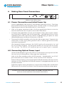
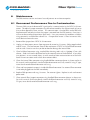
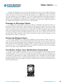
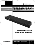
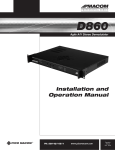
PICO MACOM
PRR
Series Optical Return Receiver
PRR Owners Manual
Please read this manual thoroughly before use.
Keep this manual handy for future reference.
Visit Our Web-Site www.picomacom.com
Contact Us 858.546.5050
Toll Free 800.421.6511
Fiber Optic Series
PICO MACOM
Pico Macom PRR Optical Return Receiver
OWNERS MANUAL
This manual is intended for use by purchasers of Pico Macom PRR receiver(s) and their qualified technicians.
This document is the property of Pico Macom, and embodies proprietary subject matter. All design, manufacture, reproduction, use and sale rights regarding the same are expressly reserved. This manual may not be
reproduced without written consent from Pico Macom. All copyright, patent and trade secrets for this manual,
the product, and its included software are expressly reserved by Pico Macom.
SAFETY CONSIDERATIONS
Caution
Risk of electrical Shock
Do Not Open
Avis – Risqué de choc electrique Ne Pas Ouvrir
For user safety, one or more of the caution labels shown here may be affixed to the side or rear
panels of this equipment. The significance of the two symbols enclosed by triangles is described
below.
This symbol means that dangerous voltages are present within the equipment. These
voltages are not insulated and may be of sufficient strength to cause serious bodily
injury if touched. This symbol may also appear on schematics.
This symbol calls attention to a critical procedure or means that refer you to the instruction manual for operating or service information. Only qualified service personnel are to install or service the equipment. This symbol may also appear in text and
on schematics.
WARNIN G: To reduce the risk of fire or electrical shock, do not expose this equipment to rain or
moisture.
CONTACT US 858.546.5050
www.picomacom.com
PICO MACOM
Fiber Optic Series
IMPORTANT SAFEGUARDS
Pico Macom strongly advises you to read and understand the following safety instructions prior to installing
and operating this equipment.
•
Read These Instructions First. All safety and operating instructions should be read before installing or
operating this equipment. Safety and operating instructions should be retained for future reference.
•
Retain This Instruction Manual. Safety and operating instructions should be retained for future reference.
•
Heed Warnings. All warnings on the equipment and in this Owner’s Manual should be adhered to.
•
Ventilation. Do not block or cover openings in this equipment. These are provided for ventilation and
protection from overheating. Maximum operating ambient temperature is 40°C.
•
Power Sources. Operate this equipment only from the type of power source indicated on the rear panel.
CAUTION: For continued protection against risk of fire, replace the fuse (if necessary) with one of
only the same type and rating.
•
Grounding or Polarization. This equipment may be equipped with a polarized AC line plug (a plug having one blade wider than the other or a different shape). This plug will fit into the power outlet only one
way. This is a safety feature. If you are unable to insert the plug into the outlet, try reversing the plug. If
the plug still does not fit, contact your electrician to replace your obsolete outlet. Do not defeat the safety
purpose of a polarized plug.
•
Servicing. Refer all servicing to qualified personnel. Opening or removing covers may expose dangerous
voltages. When replacement parts are required, make sure the service technician uses only replacement
parts recommended by Pico Macom. Unauthorized substitutions may result in fire, electric shock, or improper operation of the unit.
•
Cleaning. Unplug the unit from the AC power outlet before cleaning. Do not use liquid or aerosol
cleaners.
•
Lightning. For added protection during a lightning storm or when the equipment is left unattended or
unused for long periods, unplug it from the power outlet and disconnect the cables between the equipment and the antenna subsystem. These precautions will prevent damage to the equipment that could be
caused by lightning strikes or power line surges.
•
NOTE TO CATV SYSTEM INSTALLERS: This reminder is provided to call your attention to NEC Articles
810-21, 820-22, and 820-40 that provide guidelines for proper grounding. In particular, these articles
specify that the cable ground shall be connected to the building grounding system, as close to the point
of cable entry as practical.
•
Optical Output Safety, General. Optical Transmitter units that are used with the PRR receivers may emit
harmful invisible laser radiation. These products may emit harmful laser radiation if powered on and the
case is opened or the beam path is exposed.
CONTACT US 858.546.5050
www.picomacom.com
PICO MACOM
Fiber Optic Series
Laser Safety Information:
The PRR Receivers are designed for use with fibers that have output power levels that are classified as Class 1M
per IEC/EN 60825-1/A2:2001 and comply with FDA/CDRH, 21 CFR 1040.10 and 1040.11 except for
deviations pursuant to Laser Notice No. 50 dated 26 July, 2001.
When using Optical signals of these levels, viewing the laser output or the fiber output with certain optical
instruments (for example, eye loupes, magnifiers and microscopes) within a distance of 100 mm may pose an
eye hazard.
CONTACT US 858.546.5050
www.picomacom.com
PICO MACOM
Fiber Optic Series
TABLE OF CONTENTS
Chapter 1 Introduction.................................................................................................................. 6
1. Introducing the Pico Macom PRR Optical Return Receiver............................................. 6-7
Chapter 2 Specifications................................................................................................................ 8
1. RF Performance............................................................................................................... 8
2
Optical Performance....................................................................................................... 8
3. General........................................................................................................................... 8
Chapter 3 Installation and Operation............................................................................................ 9
1. Unpacking The Unit........................................................................................................ 9
2. Before Mounting............................................................................................................. 9
3. Rack Mounting................................................................................................................ 9
3.1 Spacing........................................................................................................................... 9
3.2 Cooling........................................................................................................................... 9
3.3 Securing the Unit............................................................................................................ 9
4. Making Rear Panel Connections...................................................................................... 10
4.1 Power Connection and Initial Power Up......................................................................... 10
4.2 Connecting Optical Power Input..................................................................................... 10
4.3 RF Output Connections................................................................................................... 11
5. Front Panel Operations................................................................................................... 11
5.1 Setting RF ADJUST.......................................................................................................... 11
6. Maintenance................................................................................................................... 12
6.1 Decreased Performance Due to Contamination............................................................... 12
Chapter 4 Customer Support Information...................................................................................... 13
1. If You Need Help............................................................................................................ 13
2. Repair Procedure............................................................................................................ 13
3. Claims............................................................................................................................. 13
WARRANTY................................................................................................................................... 14
CONTACT US 858.546.5050
www.picomacom.com
Fiber Optic Series
PICO MACOM
Chapter 1
Introduction
1.
Introducing the Pico Macom PRR Optical Return
Receiver
OPTICAL RETURN PATH RECEIVER
RECEIVER 1
POWER
RF ADJUST
ON LINE
RECEIVER 1
OPTICAL
RF ADJUST
ON LINE
RECEIVER 1
OPTICAL
RF ADJUST
ON LINE
RECEIVER 1
OPTICAL
RF ADJUST
ON LINE
OPTICAL
The Pico Macom PRR Optical Return Receiver is a 1 RU (1.75 high x 19 inches wide) rack
mountable chassis with one, two, or four Optical Return Receivers included. The PRR-1 model
has one optical input and one RF output; the PRR-2 model has two optical inputs and two corresponding optical outputs; the PRR-4 model has four optical inputs and four corresponding RF
outputs. The PRR-1, PRR-2, and PRR-4 models are otherwise the same and this manual refers
to the PRR to include all three models unless specifically stated as PRR-1, PRR-2, or PRR-4.
(PRR-4 is shown above.)
2 OPTICAL IN
1 OPTICAL IN
ON/OFF
RF
RF
RF
RF
90-264 VAC
47-63 Hz
The PRR receives a wide range of optical carriers, from 1290 nm to 1600 nm, allowing use
with common 1310 nm and common 1550 nm wavelength transmitters. The optical input is
monitored and the front panel OPTICAL LED is lighted when a signal in the 1290 to 1600 nm
wavelengths is present.
Optical input connectors on the standard PRR are SC/APC type, common to the cable industry
and used for their low loss and back reflection. Other connectors, most commonly, FC/APC
type are used and may be available; see your sales representative for special ordering.
The PRR outputs RF signals within the 5 to 200 MHz range, using a cable industry standard Fconnector. Each RF signal taken from the optical input, effectively providing 1, 2 or 4 separate
receivers in one chassis. These signals may carry analog NTSC modulated carriers or QPSK or
QAM digital carriers or any mixture of carriers within the 5-200 MHz. range. Each RF output
of up to 45 dBmV may be attenuated using front panel adjustments.
There is no AGC in this unit. Each of the 2 or 4 outputs has a rear panel test port at approximately -20 dBc from the primary outputs, so you may monitor the RF signal without intruding
on the system operation.
The PRR is used typically in a hub to receive return path signals for the HFC nodes. The PRR
will operate satisfactorily with typical nodes from any manufacturer which can provide the
PRR’s required input power level in the return path link.
CONTACT US 858.546.5050
www.picomacom.com
PICO MACOM
Fiber Optic Series
The PRR receiver includes an autoranging power supply and may be installed in 120 or 240 VAC
systems by purchasing an appropriate power cord at the local PC computer shop if the supplied
cord is not appropriate. (A NEMA-15P is supplied in North America.) When powered, the front
panel POWER LED will be lighted and each receiver’s ONLINE LED will be lighted. Operation is
simple, with only the RF ADJUST to be configured and, once set up for your application, the PRR
will continued to operate unattended. The PRR will return to your set operating condition after
power outages and brown-outs.
This manual details the unit specifications, describes any issues that may be critical to your installation, discusses the operation, and, finally, outlines actions if you have problems with the unit.
If you read and follow the installation and operation chapters, the PRR should provide you years
of simple, reliable operation. In case of difficulty, the PRR is supported by the Standard Gold
Warranty program.
CONTACT US 858.546.5050
www.picomacom.com
Fiber Optic Series
PICO MACOM
Chapter 2
Specifications
1.
RF Performance
SPECIFICATION
LIMITS
Frequency Range
5 to 200 MHz
Connector
F-connector, female
Impedance
75 ohm
Output Return Loss
> 8 dB
Output RF Level
> 45 dBmV
RF Output Control Range
> 10 dB
RF Frequency Response (Flatness)
+ 1.5 dB
Carrier–to-Noise Ratio
> 50 dBc*
Composite Second Order (CSO)
> 60 dBc*
Composite Triple Beat (CTB)
> 65 dBc*
Rear Panel Test Port Level
-20 dB from primary output, typ.
* Results typical, based 0 dBm Optical Return Receiver input level.
2.
Optical Performance
SPECIFICATION
LIMITS
Wavelength
1290-1600 nm.
Input Level
-2 to +1 dBm
Output Connector
SC/APC (FC/APC optional)
Return Loss
> 45 dB
3.
General
SPECIFICATION
LIMITS
Input Power
90 VAC to 264 VAC at 47 Hz to 63 Hz, 30 watt typ.
Power Cord
Standard: NEMA 15P to IEC320 male on chassis.
Special order possible
Fuse
5MF 500/250V (BEL) (spare in IEC320 socket)
Temperature Range
-10 to +50°C (+40°C max. recommended)
Relative Humidity (non-condensing)
0 to 95%
Altitude
0 to 15,000 ft
Weight
PRR-1: 7.2 lb.| PRR-2: 7.5 lb. | PRR-4: 8.2 lb.
Size:
1 RU (1.75”)H x 19”W x 13”D
CONTACT US 858.546.5050
www.picomacom.com
PICO MACOM
Fiber Optic Series
Chapter 3
Installation and Operation
1.
Unpacking the Unit
Please inspect the cartons on receipt and note damage to the carton and inspect for possible
unit damage. If damage is found, please contact shipper immediately, before unpacking, to
follow that shipper’s procedure for claims.
Please open the carton and unpack carefully. Locate the power cord. Do not connect a unit
to power if there is serious mechanical damage to prevent possibly unsafe conditions.
2.
Before Mounting
The PRR receiver has no internal configuration switches and no internal user adjustments or
controls. To prevent unsafe conditions, please do not open the unit. Opening the PRR receiver will also void the warranty.
3.
Rack Mounting
The unit is designed for installation in an EIA standard 19-inch (480 mm) equipment rack.
3.1 Spacing
It is generally a good practice to leave one open slot (approximately 1 3/4 inch) between
units to allow for cooling and provide maximum reliability. From the front of the rack, cover
any open slots with a blank plate to prevent dust from entering the rack.
3.2 Cooling
If other equipment is installed in the same rack or nearby racks as the PRR receiver, check
to ensure that adequate cooling measures have been provided for all equipment in the rack.
Do not restrict the airflow through the equipment’s vents on the top cover. The PRR has been
designed to effectively dissipate its own heat, but heat from other rack-mounted components
may adversely affect the unit, including side exhaust an adjacent rack.
3.3 Securing the Unit
Slide the PRR receiver into the rack opening. Please use FOUR mounting screws in the front panel mounting handles (included with the unit). Insert one screw in the lower hole on the left and on the right, and then snug both screws to hold the chassis. Place additional screws in the upper holes, and screw until snug. Tighten all four screws equally and securely.
CONTACT US 858.546.5050
www.picomacom.com
Fiber Optic Series
PICO MACOM
OPTICAL RETURN PATH RECEIVER
RECEIVER 1
POWER
4.
RF ADJUST
ON LINE
RECEIVER 1
OPTICAL
RF ADJUST
ON LINE
RECEIVER 1
OPTICAL
RF ADJUST
ON LINE
RECEIVER 1
OPTICAL
RF ADJUST
ON LINE
OPTICAL
Making Rear Panel Connections
2 OPTICAL IN
1 OPTICAL IN
ON/OFF
RF
RF
RF
RF
90-264 VAC
47-63 Hz
PRR Rear Panel (PRR-4 Shown)
4.1 Power Connection and Initial Power Up
Insert the supplied power cord into the IEC320 male power socket on the chassis. Plug the opposite end of the cord into your local power source. The PRR includes an autoranging power
supply for power source of 120 or 220 or 240 VAC, 50 or 60 cycles.
• Make sure the power connection includes a third wire ground; please do not use two wire
extension cords between the main power source and the PRR receiver.
• If the power cord supplied does not match your local power sockets, please acquire a replacement at the local PC computer store with the correct plug. A qualified technician may cut the
supplied plug off the cord, strip the wires and affix an appropriate plug, but please use a three
connection power plug and connect all three wires in the cord.
• The rear panel includes a grounding stud (at the right side near power input). To prevent noise
and hum bars in the RF signal, please ground this stud to a common ground with the other
signal processing equipment.
After connecting the power cord, press the ON/OFF switch on the rear panel to “on” and
the unit will begin to operate. The front panel POWER LED will light and the ONLINE
LEDs will light. The OPTICAL LED should not light until an optical signal is connected.
4.2 Connecting Optical Power Input
Connect the desired optical signal to the OPTICAL IN connector on the rear panel of the PRR.
Your may have an incoming fiber or a fiber jumper from a patch panel.
Make sure the fiber connector matches the PRR connector. Standard product uses SC/APC
plastic connectors that are GREEN in color. Do not use a blue SC/UPC connector.
Remove and retain the plug in the rear panel optical bulkhead connector or the cover over the
connector, or lift the hinged lid of the bulkhead connector if so equipped to provide access to
the optical connector.
Prepare the jumper by cleaning the optical tip. Failure to clean the fiber cables inserted into the
PRR receiver will cause dirt to accumulate in the PRR connector and decrease output power.
Failure to clean the fiber cables before insertion into the PRR is considered abuse and
repairs due to dirty connectors are not covered under warranty.
CONTACT US 858.546.5050
www.picomacom.com
10
Fiber Optic Series
PICO MACOM
Example of a fiber cable cleaner (source: Fiber Instrument Sales, www.fiberinstrumentsales.com).
4.3 RF Output Connections
Connect a RF output coax cable to a rear panel F-connector labeled RF OUT and route to combiners, transmitters or other equipment which use the RF signal. Install a second coax for the
PRR-2 and up to 4 for the PRR-4, if desired.
You may monitor each output signal from the rear panel test port. The PRR includes a -20
dB directional coupler to divert a small amount of the signal from the primary RF OUT to this
output. The -20 dB level is approximate and varies due to parts variations.
5.
Front Panel Operations
The PRR has one user adjustment per RF output, the RF ADJUST on the front panel.
RECEIVER 1
RF ADJUST ONLINE OPTICAL
Detail of front panel for one receiver
5.1 Setting RF ADJUST
You must determine the RF level needed by the equipment receiving the RF signal from each
RF OUT port based on that equipment manufacturer’s recommendations.
We recommend using a spectrum analyzer to measure the RF OUT port’s level. Connect the
spectrum analyzer to the RF OUT port; note the spectrum analyzer may require 50-75 Ohm
matching and the loss from that matching device must be added to the spectrum analyzer reading.
The PRR, with the RF ADJUST control set to fully clockwise position will output approximately
45 dBmV. To reduce the output to the desired level, rotate RF ADJUST for the RF OUT port
with the spectrum analyzer to the desired level.
Repeat this process for each RF OUT port that you will be using.
CONTACT US 858.546.5050
www.picomacom.com
11
PICO MACOM
6.
Fiber Optic Series
Maintenance
The PRR receiver contains no internal user adjustments or maintenance points.
6.1 Decreased Performance Due to Contamination
The most likely cause of decreased RF signal quality is contamination in the OPTICAL IN connector. The optical jumper connectors may be contaminated by the slightest touch to human
skin or other apparently clean surfaces. This contamination is transferred in to the PRR bulkhead connector and remains when the jumper is removed from the PRR receiver. Over time, it
will cause decreased and intermittent input levels. Users may correct this condition as follows
using commonly available fiber cleaner kits. One possible source is Fiber Instrument Sales,
www.fiberinstrumentsales.com.
1. Remove fiber jumper from OPTICAL IN connector
2. Unplug unit from power source. Open top cover by removing 12 screws, sliding top plate back
and lift at rear. Find and remove internal fiber connector at OPTICAL IN bulkhead connector
and set aside. Exercise care that you do not bend or damage the internal fiber.
3. Clean bulkhead connector using standard fiber cleaning tools such as Optipop 2.5mm stick
cleaner. Slide stick into the bulkhead and scrub contamination of the bulkhead. A less effective solution is to use canned (clean) air with nozzle to blow contamination out of the bulkhead. Do not use cotton swabs which leave cottons debris.
4. Clean the internal fiber connector using handheld fiber connector cleaner (as shown earlier in
this manual) and insert directly into the bulkhead connector until fully seated. If using FC type,
screw ferrule onto bulkhead connector until snug.
5. Clean and insert protective cover in inside of bulkhead connector if an external fiber connector
is not to be plugged into the PRR immediately.
6. Replace PRR top cover and snug 12 screws. Do not over tighten. Replace in rack and connect
power cord.
7. Clean external fiber (jumper) connector using handheld fiber connector cleaner (as shown earlier in this manual) and insert directly into the bulkhead connector until fully seated. If using
FC type, screw ferrule onto bulkhead connector until snug.
CONTACT US 858.546.5050
www.picomacom.com
12
PICO MACOM
Fiber Optic Series
Chapter 4
Customer Support Information
1.
If You Need Help
If you need assistance while working with the Pico Macom products call Pico Macom
Field Support at 858-546-5050, or 800 421-6511 between 8 AM and 5 PM Pacific Time.
Alternatively, you may contact us via email at [email protected].
2.
Repair Procedure
Pico Macom has established a streamlined process to ensure the rapid return of products
when repair is required.
As a system operator, you must return the unit to Pico Macom for repair.
After speaking with a technician, if a Return Material Authorization (RMA) is deemed necessary, an RMA will be generated to identify the product during the receipt and repair process
and to track the product in work and during return shipment. Should you make an inquiry,
the RMA number will be required. Any communication from the repair facility will identify
the product by the RMA number.
When shipping a product for repair, please follow these steps:
•
•
•
•
•
3.
Pack the unit securely.
Enclose a note describing the problem.
Enclose a copy of the invoice showing warranty status.
Make sure the RMA number is on the outside of the box, on or near the shipping label.
Ship the unit prepaid to the repair facility indicated by the technician.
Claims
Claims for shortages, erroneous charges, or price corrections must be presented within 30
days of invoice date. Freight damage claims should be filed directly with the delivering carrier
within seven days.
NEW and UNOPENED EQUIPMENT may be returned for credit with prior approval from
Pico Macom within 30 days of invoice date. A 20 percent processing and handling charge
will be assessed on any new items returned for credit. Please call our Sales Administrator at the
number above for further information.
CONTACT US 858.546.5050
www.picomacom.com
13
PICO MACOM
Fiber Optic Series
Limited Warranty
Pico Macom warrants to the original purchaser that all of its new products are of sound design,
quality materials and workmanship at the time of manufacture and will be free from related defects
for one year from the original purchase date. Pico Macom will repair or, at its discretion, replace
without cost to the original purchaser, the product which, upon inspection by Pico Macom, appears
to be defective or not conforming to factory specifications. Pico Macom will cover the cost of parts,
labor, and return freight from factory.
Five-Year Limited Warranty
Most products designated as “Headend Electronics” are further covered by an extended 4-year
period beyond the expiration of the original 1-year warranty, for a full 5-year period. Qualified
equipment requiring factory repair during the extended 4-year period is covered under our re-certification program. Re-certification fees under this program shall not to exceed 20% of the product’s
List Price and whenever possible, Pico Macom will attempt to upgrade performance to the latest improved specification.
Warranty Limitations
This warranty excludes coverage of damage or inoperability resulting from (1) use or installation
other than in strict accordance with Pico Macom’s written instructions, (2) disassembly or repair by
someone other than Pico Macom or a Pico Macom authorized repair center, (3) misuse, misapplication
or abuse, (4) alteration, (5) lack of reasonable care or (6) wind, ice, snow, rain, lightning, power surges,
or any other weather conditions or acts of God. Pico Macom’s warranty with respect to third-party proprietary sub-assembly modules and/or private-label products are limited to the duration and terms of
third-party vendors’ warranty. Pico Macom shall in no event and under no circumstances be liable or
responsible for any consequential, indirect, incidental, punitive, direct or special damages based upon
breach of warranty, breach of contract, negligence, strict tort liability or otherwise or any other legal
theory, arising directly or indirectly from the sale, use, installation or failure of any product acquired by
buyer from Pico Macom. This limited warranty extends to the original purchaser. Pico Macom reserves
the right to modify or discontinue this warranty at Pico Macom’s sole discretion without notification.
No other warrantees are expressed or implied.
Uptime Loaner Program
Our Uptime loaner program is designed to provide domestic users of our headend products and
commercial systems the best possible support and service. This program is established to minimize
downtime resulting from equipment failure in critical service situations. We offer this program free of
charge (excluding freight) to qualified purchasers within the warranty period. The program provides a
free equipment loan of like qualified equipment enabling seamless operation for the time required to
repair and return the unit.
The process is simple. Call our Customer Service desk requesting a return-merchandise-authorization (RMA) number for the failed equipment and ask for a loaner unit. We will issue an invoice for the
List Price of the loaner unit plus shipping costs. When you receive the loaner unit, pack the failed unit
in the loaner unit’s box and ship it freight prepaid to Pico Macom for repair. When you receive the
repaired unit, a new RMA number will be provided in the box. Carefully pack the loaner unit and affix
the new RMA number on the box and ship it back to us for full credit excluding shipping costs.
CONTACT US 858.546.5050
www.picomacom.com
14
Fiber Optic Series
PICO MACOM
To qualify for the program, you must have current open-terms with us and in good standing. We
must receive your failed unit within one week after the loaner unit is shipped to you, and must likewise
receive the loaner unit within one week after the repaired unit is shipped back to you. Daily rental
fees not to exceed 10% of the equipment’s List Price will apply beyond one week after the loaner or
repaired unit are shipped to you. Other limitations may apply, so please call us for additional information on qualifying equipment and procedures. Pico Macom reserves the right to modify or discontinue
the Uptime Loaner Program at any time, and at its sole discretion.
Damage or Shortage Claims
Our shipping staff carefully packs and ships your orders in compliance with common carriers’ requirements. Please make note of any obvious damage or shortage on the freight bill or carrier’s receipt
next to your signature. The carrier’s agent must too sign acknowledging the loss. Failure to do so may
result in the carrier’s refusal to honor the claim. Please open your order immediately upon receipt to
check for concealed damage and compare the packing list to the items shipped. If damaged, keep
the original shipping cartons for possible inspection by the carrier. You must report claims for loss or
damage within 3 days of delivery, while claims for erroneous charges or price corrections must be
presented within 30 days of invoice date.
Returning Shipped Items
To return any shipped items, including those shipped for warranty repairs or credit, call our Customer Service desk to request a Return Merchandise Authorization (RMA) number. Please reference the
original invoice number and purchase date, and product serial number (if any). Be certain to mark the
RMA number on the package boldly and legibly. Unless we specify a different carrier, please ship your
returned items to us via UPS freight prepaid and fully insured. If returned for credit, we will promptly
process your request upon receipt of your return order.
Our Return Policy: Your Satisfaction Guaranteed
Our goal is your complete satisfaction. If for any reason, our products were not quite what you
anticipated, simply call your customer service rep and we will be happy to assist you in replacing or returning the order. You may return current, non-discontinued items for full credit for up to 30 days from
invoice date. Our requirements are simple: Excepting defective items, the products must be returned in
their original packaging and in re-salable condition. Restocking fees may otherwise apply beyond this
period or if products are not returned in their original condition. Please contact your customer service
rep for more information.
Five Year Limited Warranty **
CONTACT US 858.546.5050
www.picomacom.com
15
PICO MACOM
6260 Sequence Drive
San Diego
California 92121
Phone: 858.546.5050
Sales: 858.546.5055
Fax: 858.546.5051
www.picomacom.com
[email protected]
Printed in the U.S.A.