1
BES-961BC
BES-1261BC
INSTRUCTION MANUAL
Please read this manual before using the machine.
Please keep this manual within easy reach for quick reference.
NINE NEEDLE SIX HEAD ELECTRONIC EMBROIDERY MACHINE
TWELVE NEEDLE SIX HEAD ELECTRONIC EMBROIDERY MACHINE
Precautions
• Unauthorized commercial or industrial use of trademarks or copyrighted materials (such as
paintings, drawings, photos, logos, etc.) owned by other companies or persons is illegal. The
use of such materials without the permission of their owners may result in criminal or civil liability.
• This manual may be subsequently modified without prior notice.
• Brother Industries, Ltd. shall assume no responsibility for any consequences of using this manual.
Thank you very much for buying a BROTHER sewing machine. Before using your new machine,
please read the safety instructions below and the explanations given in the instruction manual.
With industrial sewing machines, it is normal to carry out work while positioned directly in front
of moving parts such as the needle and thread take-up lever, and consequently there is always a
danger of injury that can be caused by these parts. Follow the instructions from training personnel
and instructors regarding safe and correct operation before operating the machine so that you
will know how to use it correctly.
SAFETY INSTRUCTIONS
1 Safety indications and their meanings
This instruction manual and the indications and symbols that are used on the machine itself are
provided in order to ensure safe operation of this machine and to prevent accidents and injury to
yourself or other people. The meanings of these indications and symbols are given below.
Indications
DANGER
The instructions which follow this term indicate situations where
failure to follow the instructions will almost certainly result in death
or severe injury.
CAUTION
The instructions which follow this term indicate situations where
failure to follow the instructions could cause injury when using the
machine or physical damage to equipment and surroundings.
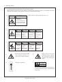
Symbols
................. This symbol (
) indicates something that you should be careful of.
The picture inside the triangle indicates the nature of the caution that must be
taken. (For example, the symbol at left means "beware of injury".)
................. This symbol (
) indicates something that you must not do.
................. This symbol (
) indicates something that you must do.
The picture inside the circle indicates the nature of the thing that must be done.
(For example, the symbol at left means "you must make the ground connection".)
BES-961BC • BES-1261BC
1
2 Notes on safety
DANGER
Wait at least 5 minutes after turning off the power switch and disconnecting the power cord from the wall
outlet before opening the face plate of the control box. Touching areas where high voltages are present can
result in severe injury.
CAUTION
Installation
Machine installation should only be carried out
by a qualified technician.
Contact your Brother dealer or a qualified electrician for any electrical work that may need to
be done.
The sewing machine weighs more than 720 kg.
The installation should be carried out by four
or more people.
Do not connect the power cord until installation is complete, otherwise the machine may
operate if the start switch is pressed by mistake, which could result in injury.
Be sure to connect the ground. If the ground
connection is not secure, you run the risk of
receiving a serious electric shock.
Be sure to wear protective goggles and gloves
when handling the lubricating oil or grease, so
that no oil or grease gets into your eyes or onto
your skin, otherwise inflammation can result.
Furthermore, do not drink the oil or grease under any circumstances, as they can cause vomiting and diarrhoea.
Keep the oil out of the reach of children.
Avoid setting up the sewing machine near
sources of strong electrical noise such as highfrequency welding equipment.
If this precaution is not taken, incorrect machine
operation may result.
The casters should be secured in such a way
so that they cannot move.
When securing the cords, do not bend the cords
excessively or fasten them too hard with
staples, otherwise there is the danger that fire
or electric shocks could occur.
Sewing
This sewing machine should only be used by
operators who have received the necessary
training in safe use beforehand.
Attach all safety devices before using the sewing machine. If the machine is used without
these devices attached, injury may result.
The sewing machine should not be used for any
applications other than sewing.
Do not touch any of the moving parts or press
any objects against the machine while sewing,
as this may result in personal injury or damage
to the machine.
Turn off the power switch at the following times,
otherwise the machine may operate if the start
switch is pressed by mistake, which could result in injury.
• When threading the needle
• When replacing the bobbin and needle
• When not using the machine and when leaving the machine unattended
Do not get on the table.
Table may be damaged.
2
Do not touch the pulse motor and sewing machine bed section during operation or for 30 minutes after operation. Otherwise burns may result.
If an error occurs in machine operation, or if abnormal noises or smells are noticed, immediately
turn off the power switch. Then contact your
nearest Brother dealer or a qualified technician.
If the machine develops a problem, contact your
nearest Brother dealer or a qualified technician.
BES-961BC • BES-1261BC
CAUTION
Cleaning
Turn off the power switch before starting any
cleaning work, otherwise the machine may operate if the start switch is pressed by mistake,
which could result in injury.
Be sure to wear protective goggles and gloves
when handling the lubricating oil or grease, so
that no oil or grease gets into your eyes or onto
your skin, otherwise inflammation can result.
Furthermore, do not drink the oil or grease under any circumstances, as they can cause vomiting and diarrhoea.
Keep the oil out of the reach of children.
Maintenance and inspection
Maintenance and inspection of the sewing machine should only be carried out by a qualified
technician.
If the power switch needs to be left on when
carrying out some adjustment, be extremely
careful to observe all safety precautions.
Ask your Brother dealer or a qualified electrician to carry out any maintenance and inspection of the electrical system.
Use only the proper replacement parts as specified by Brother.
Turn off the power switch and disconnect the
power cord from the wall outlet at the following
times, otherwise the machine may operate if the
treadle is depressed by mistake, which could
result in injury.
• When carrying out inspection, adjustment
and maintenance
• When replacing consumable parts such as
the rotary hook and knife.
If any safety devices have been removed, be absolutely sure to re-install them to their original
positions and check that they operate correctly
before using the machine.
Any problems in machine operation which result from unauthorized modifications to the machine will not be covered by the warranty.
BES-961BC • BES-1261BC
3
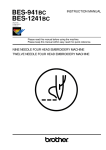
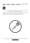
3 Warning labels
* The following warning labels appear on the sewing machine.
Please follow the instructions on the labels at all times when using the machine. If the labels have been
removed or are difficult to read, please contact your nearest Brother dealer.
1
Safety devices: Finger guard, Belt cover, etc.
CAUTION
Moving parts
may cause injury.
Operate with safety devices.
turn off main switch before
changing needle, cleaning
etc.
2
3
DANGER
GEFAHR
Hochspannung
verletzungsgefahr!
Un voltage non adapté
provoque des blessures.
Turn off main
switch and unplug
power cord before
opening this cover.
Vor Öffnen des
Gehäuses
Hauptschalter
ausschalten und
Netzstecker ziehen!
Pour ouvrir cette plaque,
couper le contact
general de la machine
et debrancher le cable
d’alimentation.
CAUTION
PELIGRO
DANGER
Hazardous voltage
will cause injury,
ACHTUNG
Un voltaje inadecuado
puede provocar las
heridas.
Antes de abrir esta
tapa, desconecte la
máquina y
desenchufela de la red.
ATTENTION
ATENCION
Table may
Der Tisch kann
be damaged. beschädigt
werden.
Vous risquez
d’endommager
la table.
La mesa se
puede dañar.
Do not get on Nicht auf den
the table.
Tisch stehen.
No montez pas
sur la table.
No pise la
mesa.
4
Never touch or push the thread
take up during operation as it
may result in injuries machine.
5
6
Direction of operation
7
Never touch or push the
needle bar during operation
as it may result in injuries or
damage to the sewing machine.
高温注意
CAUTION
Do not touch this part during activitation or
for 30 minutes after shut-off. Otherwise burns
may result.
4
BES-961BC • BES-1261BC
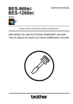
6
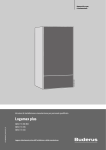
4
3
Finger guard
7
Belt cover
5
3
2
■BES-961BC
7
1
2
1
BES-961BC • BES-1261BC
5
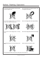
Before Starting Operation
Do not force open the shutter for direct contact
with the magnetic area.
Do not bring disks near magnetic matters such
as magnetic screwdriver.
Do not store floppy disks in an extremely
high or low ambient temperature.
Do not use floppy disks under high humidity.
Do not use or store floppy disks in a dusty
place.
Do not store floppy disks under direct sunlight.
Do not bend the disk. Do not put things on the
disk.
Avoid contact with solvent or drink.
Do not remove the disk out of the drive during the access lamp is lit.
6
BES-961BC • BES-1261BC
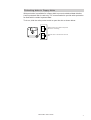
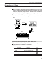
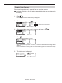
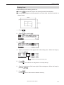
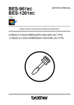
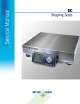
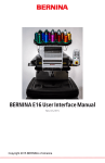
Protecting data in floppy disks
Write-protection is available for a floppy disk to prevent undesired data deletion.
A write-protected disk is read-only. It is recommended to provide write-protection
for disks which contain important data.
To do so, slide the write-protect notch to open the slot as shown below.
Slide the notch in this direction to prevent
data loss or overwriting.
Slide the notch in this direction to write
data.
BES-961BC • BES-1261BC
7
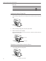
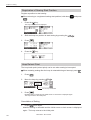
Procedure of Reading This Manual
Explanation of models
This manual explains two models:
- BES-961BC (9 needles)
- BES-1261BC (12 needles)
Explanation for individual model is provided by identifying the model name. Check
the model before using the machine. The display is BES-961BC.
Configuration of this manual
This manual consists of the following chapters:
Chapter 1
Preparation of Embroidery Machine
This Chapter describes the specifications, installation and preparatory procedures of
starting up the machine.
Chapter 2
Embroidering Procedures
Provides explanations on the operation panel and briefly reviews the flow of
embroidering processes.
Chapter 3
Selection of Data and Embroidering
This Chapter describes procedures of reading sewing data and sewing.
Chapter 4
Editing of Embroidering Data
Explains how to edit the embroidery data.
Chapter 5
Setting
This Chapter describes procedures of setting the machine and working environment.
Chapter 6
Operation of Machine
Provides information on machine operation during embroidering.
Chapter 7
Maintenance
Describes appropriate maintenance of the machine.
Chapter 8
Standard Adjustment
Explains how to adjust the needles.
8
BES-961BC • BES-1261BC
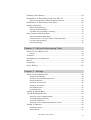
Chapter 9
List of Error Messages
Provides information on error codes and action to be taken.
Chapter 10
Troubleshooting
Provides troubleshooting for the machine.
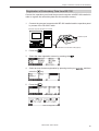
Connection and Installation of Optional Equipment
Describes connections between the machine/computer and optional equipment
available.
BES-961BC • BES-1261BC
9
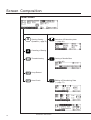
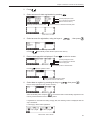
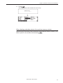
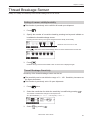
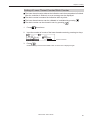
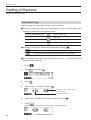
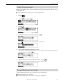
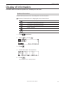
Screen Composition
Initial Screen
START
STOP
Starting Sewing
Selection of Embroidery data
Operation (→ page 72)
(→ page 61)
Canceling of Sewing
Thread trimming
Setting of Needle Bars
(→ page 92)
Hoop Retract
Area Check
Editing of Enbroidering Data
(→ page 77)
↓
↓
10
BES-961BC • BES-1261BC
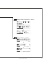
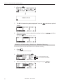
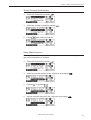
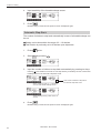
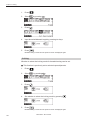
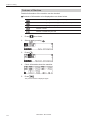
Setting of thread breakage sensor (→page 93)
↓
↓
Setting of Machine (→page 96)
↓
↓
BES-961BC • BES-1261BC
11
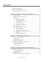
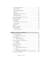
Contents
SAFTY INSTRUCTIONS............................................................................... 1
Before Starting Operation .......................................................................... 6
Procedure of Reading This Manual ........................................................... 8
Screen Composition ................................................................................. 10
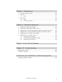
Chapter 1 Preparation of Embroidery Machine
1. Specifications ..................................................................................... 18
2. Names of Machine Components ....................................................... 19
3. Installation ........................................................................................... 21
3-1.
3-2.
3-3.
3-4.
3-5.
3-6.
3-7.
Transportation of Machine ..................................................................... 21
Installation of Machine ........................................................................... 23
Preparation of Needle Bar Case ............................................................ 24
Mounting of Table .................................................................................. 26
Mounting of Cotton Stand ...................................................................... 30
Lubrication to Needle Bar Case ............................................................. 32
Grounding .............................................................................................. 33
4. Preparation for Embroidering ............................................................ 34
4-1.
4-2.
4-3.
4-4.
4-5.
4-6.
Upper Threading .................................................................................... 34
Replacement of Bobbin .......................................................................... 37
Replacing and Selecting Needle ............................................................ 38
Attachment of Embroidery Hoop and Frame ......................................... 39
Bed Retract ............................................................................................ 45
Adjustment of Thread Tension ............................................................... 47
Chapter 2 Embroidering Procedures
Functions of Operation Panel .................................................................. 50
Operation Panel ................................................................................................ 50
Switches at Machine Heads .............................................................................. 53
Switches on Tension Plate ................................................................................ 53
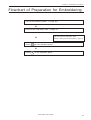
Flowchart of Preparation for Embroidering ............................................ 55
Turn on the Machine Power .............................................................................. 56
Retrieve the Embroidery Data ........................................................................... 57
Start Embroidering ............................................................................................ 57
Chapter 3 Selection of Data and Embroidering
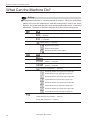
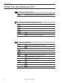
What Can the Machine Do? ...................................................................... 60
Selection of Embroidery Data ........................................................................... 60
Embroidering Operation .................................................................................... 60
Selection of Data ....................................................................................... 61
Registration of Embroidery Data from Floppy Disk ........................................... 61
12
BES-961BC • BES-1261BC
Reading from Memory .............................................................................. 64
Registration of Embroidery Data from BE-100 ....................................... 65
Deletion of Embroidery Data from Machine Memory ........................................ 66
Modification of Embroidery Data Name .................................................. 68
Sewing Operation ...................................................................................... 72
Before Starting Sewing ..................................................................................... 72
Starting Sewing Operation ................................................................................ 72
Feedhold and Cancellation of Sewing ............................................................... 73
Step Forward and Step-Back ................................................................... 74
Step Forward/Step-Back Mode ......................................................................... 74
Setting Amount or Timing of Step Forward/Step-Back ..................................... 74
For Step Forward (Back) ................................................................................... 75
Resuming Sewing ............................................................................................. 75
Chapter 4 Editing Embroidering Data
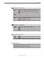
What Can the Machine Do? ...................................................................... 78
Editing ............................................................................................................... 78
Rotation ...................................................................................................... 79
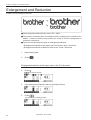
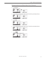
Enlargement and Reduction ..................................................................... 80
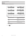
Mirror .......................................................................................................... 82
Repetition ................................................................................................... 84
Other Editing.............................................................................................. 86
Chapter 5 Settings
What Can the Machine Do? ...................................................................... 90
Setting of Needle Bars ...................................................................................... 90
Setting of Thread Breackage Sensor ................................................................ 90
Setting of Machine ............................................................................................ 90
Setting of Environmenet .................................................................................... 91
Display of Information ....................................................................................... 91
Hoop Retract point ............................................................................................ 91
Hoop Movement ................................................................................................ 91
Setting of Needle Bars .............................................................................. 92
Thread Breakage Sensor .......................................................................... 93
Setting of sensor validity/invalidity .................................................................... 93
Thread Breakage Sensitivity ............................................................................. 93
Automatic Step-Back ......................................................................................... 94
Setting of Lower Thread Counter/Stitch Counter .............................................. 95
Setting of Machine .................................................................................... 96
Embroidery Hoop .............................................................................................. 96
Speed Range .................................................................................................... 97
BES-961BC • BES-1261BC
13
Speed of Each Speed Range ............................................................................ 98
Setting of Mending ............................................................................................ 99
Thread Trimming Length ................................................................................. 101
Thread Withdrawal Feed Length ..................................................................... 101
Inching ............................................................................................................. 102
Sewing Area .................................................................................................... 103
Registration of Sewing Start Position .............................................................. 103
Hoop Retract Point .......................................................................................... 104
Hoop Automatic Retract .................................................................................. 104
Movement to Registered Sewing Start Point .................................................. 105
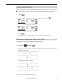
Setting of Environment ........................................................................... 106
Return to Start Point ........................................................................................ 106
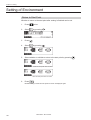
Speed Range .................................................................................................. 107
Power Voltage ................................................................................................. 107
Setting of RS-232C Communication Speed .................................................... 108
Display Language ........................................................................................... 109
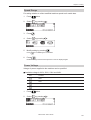
Alarm Sound ................................................................................................... 110
Boring .............................................................................................................. 111
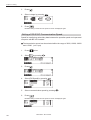
Display of Information ............................................................................ 113
Pattern Information .......................................................................................... 113
Features of Machine ....................................................................................... 114
Information about Versions ............................................................................. 115
Chapter 6 Operation of Machine
1. Operating Procedures ...................................................................... 118
1-1.
1-2.
Power Source ...................................................................................... 118
Preparation for Embroidering ............................................................... 118
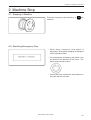
2. Machine Stop .................................................................................... 119
2-1.
2-2.
Stopping of Machine ............................................................................ 119
Resetting Emergency Stop .................................................................. 119
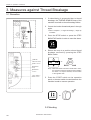
3. Measures against Thread Breakage ............................................... 120
3-1.
3-2.
Remedies ............................................................................................. 120
Mending ............................................................................................... 122
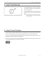
4. Jog Embroidering ............................................................................. 123
5. Hoop Feed Position .......................................................................... 123
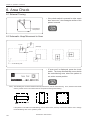
6. Area Check ........................................................................................ 124
6-1.
6-2.
External Tracing ................................................................................... 124
Automatic Hoop Movement in Area ..................................................... 124
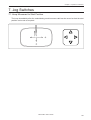
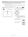
7. Jog Switches ..................................................................................... 125
7-1.
7-2.
Hoop Movement to Start Position ........................................................ 125
Inching Mode during Embroidering (Forcible Hoop Movement) .......... 126
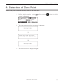
8. Detection of Zero Point .................................................................... 127
14
BES-961BC • BES-1261BC
Chapter 7 Maintenance
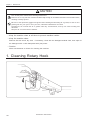
1. Cleaning Rotary Hook ...................................................................... 130
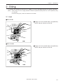
2. Oiling .................................................................................................. 131
2-1.
Head .................................................................................................... 131
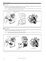
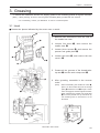
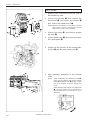
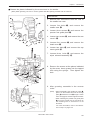
3. Greasing ............................................................................................ 133
3-1.
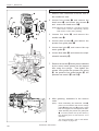
3-2.
Head .................................................................................................... 133
Feed Guide Section ............................................................................. 137
Chapter 8 Standard Adjustment
1. Adjusting Needle Bar Height ........................................................... 140
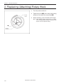
2. Replacing (Attaching) Rotary Hook ................................................ 144
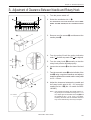
3. Adjustment of Clearance Between Needle and Rotary Hook ....... 145
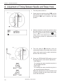
4. Adjustment of Timing Between Needle and Rotary Hook ............ 146
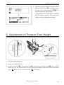
5. Adjustment of Presser Foot Height ................................................ 147
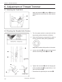
6. Adjustment of Thread Trimmer ....................................................... 148
6-1.
6-2.
6-3.
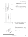
Attaching the Fixed Knife ..................................................................... 148
Checking the Movable Knife Position .................................................. 148
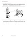
Adjusting the Belt Tention .................................................................... 150
Chapter 9 List of Error Message
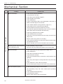
Chapter 10 Troubleshooting
Mechanical Section ................................................................................. 156
Electrical Section .................................................................................... 158
Connection and Installation of Optional Equipment
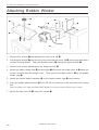
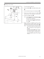
Attaching Bobbin Winder ....................................................................... 160
BES-961BC • BES-1261BC
15
16
BES-961BC • BES-1261BC
Chapter 1
Preparation of Embroidery Machine
Chapter 1 Preparation of Embroidery Machine
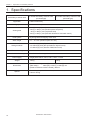
1. Specifications
Embroidery machine used
Application
Pattern embroidery
Sewing speed
Maximum 1000 spm
12 needle embroidery machine head
(six-head type)
Sewing area
450 (V) x 400 (H) mm (border frame area)
430 (V) x 300 (H) mm (tubular square hoop area)
85 (V) x 360 (H) mm (cap frame area)
450 (V) x 600 (H) mm (with bed retracted or with head control)
Feed system
By timing belt and stepping motor drive
Stitch length
0.1 ~ 12.7 mm (minimum pitch: 0.1 mm)
Storage medium
3.5 2DD floppy disk (Tajima format)
3.5 2HD floppy disk (the equivalent to Tajima format)
3.5 2DD floppy disk (Barudan FDR/FMC format)
Thread trimming
Automatic thread trimmer
Needle thread breakage
Power supply
Weight
Dimensions
Options
18
9 needle embroidery machine head
(six-head type)
Needle thread breakage detector
Single phase 200 V, 220 V, 230 V, 240 V,1.7 kVA
720 kg
720 kg
(Before assembly) 3650 (W) x 810 (L) x 1650 (H) mm
(After setup)
3650 (W) x 1400 (L) x 1650 (H) mm
(Distance between machine heads) 400 mm
Embroidery hoops in different sizes, Bobbin winder,
Parts for boring
BES-961BC • BES-1261BC
Chapter 1 Preparation of Embroidery Machine
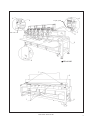
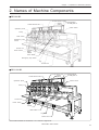
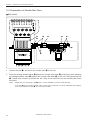
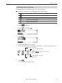
2. Names of Machine Components
■ BES-961BC
Thread tension switch
Thread guide B
Thread
Thread guide C
guide A
Thread tension dial
Cotton stand
Operation panel
Pulley
Start switch
Emergency stop
switch
Control box
Power switch
F table
Start switch
Emergency stop switch
Leg
Thumb bolt
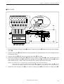
■ BES-1261BC
Thread tension switch
Thread
guide A
Thread tension dial
Operation panel
Thread guide B
Thread guide C
Cotton stand
Pulley
Control box
Power switch
F table
Head switch
Leg
Thumb bolt
The machine heads are numbered 1 to 6 from the right front.
BES-961BC • BES-1261BC
19
Chapter 1 Preparation of Embroidery Machine
■ Accessories
Standard Accessories
Embroidery hoop
• Tubular square hoop 30 x 43 (6)
• Tubular round arm set R (6)
• Tubular round arm set L (6)
Optional Accessories
• Holder base 30 x 43 (6)
Other embroidery hoops in different sizes
• Sash frame assembly
* Other Tajima embroidery hoops that can
be used with BAS-412A and 416A
• Cap frame (6)
Cap frame drive assembly (6)
Base frame set (12)
Set frame base set (1)
Others
20
F table assembly
• Bobbin winder
• Parts for boring
BES-961BC • BES-1261BC
Chapter 1 Preparation of Embroidery Machine
3. Installation
DANGER
Embroidery machines should be installed only
by trained engineers.
Electric wiring should be laid by your distributor or electric experts.
A machine weighs more than 720 kg. Installation should be carried out by 4 or more workers.
Install a machine in a place away from a highfrequency welding machine or other machines
that may generate a strong electric noise. Failure to do so may cause the embroidery machine
to malfunction.
Establish grounding as designated. Improper
grounding may result in an electric shock.
Do not connect the power source until installation is completed. Doing so may start the machine unintentionally through an accidental
activation of the START switch, resulting in
bodily injuries.
* After installation is completed, get the power supply from a dedicated outlet.
* When connecting multiple machines, exercise care not to exceed the capacity of the outlet.
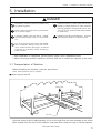
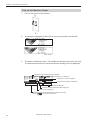
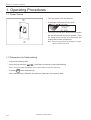
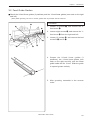
3-1 Transportation of Machine
When relocating the machine, push the steel frame.
Note) Never push the cover or carriage.
■ When using a fork lift
Center pillar
a
a +20
Lift forks
Open the forks of the lift approximately 10 cm to the right from the even position to the center
pillar viewed from the rear of the machine, and pass them under the legs to lift the machine.
BES-961BC • BES-1261BC
21
Chapter 1 Preparation of Embroidery Machine
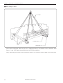
■ When using a crane
Rope
L-shaped steel
Rectangular bar
Place two rectangular bars on the four L-shaped steels on the bottom of the machine steel
frame. Loop four ropes around the bars and lift the machine.
Note) When lifting the machine, make sure that the ropes do not contact the machine table or the tension plate.
22
BES-961BC • BES-1261BC
Chapter 1 Preparation of Embroidery Machine
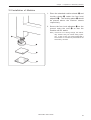
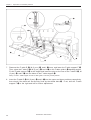
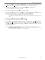
3-2 Installation of Machine
1. Place the attached cushion sheets w and
leveling plates e under the four level
adjusters q. The leveling plates e should
be placed above the cushion sheets
respectively.
2. Secure the four level adjusters q on the
ground using the nuts r so that the
machine will be stable.
Note) If the floor is not strong enough, the embroidery machine may be rocked during operation. In such a case, it is recommended that a
secure base of concrete be placed below the
embroidery machine.
r
q
e
w
BES-961BC • BES-1261BC
23
Chapter 1 Preparation of Embroidery Machine
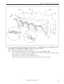
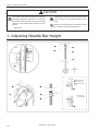
3-3 Preparation of Needle Bar Case
■ BES-961BC
w
q
y
e
i
u
r
t
1. Loosen the bolt q, and move the needle case w to the left.
2. Press the change bracket collar r against the change case base e on the light, while pressing
the change bracket collar t against the change case base y on the left, and tighten the bolt
q. Check that needles at needle bar No.1 and 9 are inserted into the needle plate holes
smoothly.
Note)
• Check that the connecting shaft u does not have backlash in the horizontal direction.
• If the bolt i of the change bracket collar on the right is loosened, it may be dislocated during adjustment of the needle bar case w. Do not loosen this bolt.
24
BES-961BC • BES-1261BC
Chapter 1 Preparation of Embroidery Machine
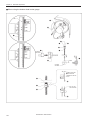
■ BES-1261BC
Bridge
r
Connecting shaft
Fixing bracket
Fixing bracket B
t
o
q
q
o
u
y
i
e
w
1. Remove 3 pieces of fixing screw q,loosen 2 pieces of screw w and remove the color change
cover e.
2. Remove the bolts r and detach the fixing bracket for transportation from the bridge and the
connecting shaft.
3. Loosen the bolts t and move the needle bar case y left side.
4. Press the change bracket collar i against the change case base u, while pressing the left
side change bracket collar o against the change case base u, and tighten the bolts t.Check
that needle bar No.1 and 12 are inserted into the needle plate holes smoothly.
(Notes) • Check that ther is no play for the connecting shaft in the horizontal direction.
• If the bolt of the right side change bracket collar i is loosened, the change bracket collar i may be
dislocated and adjusting position of the needle bar case y will be required. So don’t loosen this bolt.
5. Attach the color change cover e by 3 pieces of fixing screw q and 2 pieces of fixing screw w.
BES-961BC • BES-1261BC
25
Chapter 1 Preparation of Embroidery Machine
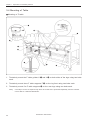
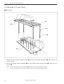
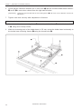
3-4 Mounting of Table
■ Mounting of F table
q
r
q
w
q
w
e
e
w
1. Tentatively mount the F table guides U q and L w on both sides of the legs using two bolts
each.
2. Tentatively mount there F table supports F e on the leg front using two bolts each.
3. Tentatively mount five F table stoppers r on the rear legs using two bolts each.
Note)
• The steps 1 and 3 are required only when the F table set is purchased separately from the machine.
• The F table is a standard attachment.
26
BES-961BC • BES-1261BC
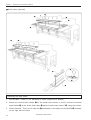
Chapter 1 Preparation of Embroidery Machine
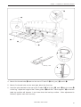
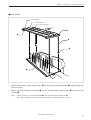
o
i
Pin
t
y
u
q
Lower by 1 mm
e
4. Mount four thumb bolts i each on the rear of F table R t, M (2 pcs.) y, and L u.
5. Mount five thumb bolts on the steel pipe below the front leg.
6. Insert the pins attached to the rear of the F table R t, M (2 pcs.) y, and L u into the cover o
on the leg. Adjust the height of the F table guide U q and the F table support F e so that the
table top surface will become 1 mm lower than the bed top surface. After adjustment is
finished, tighten each bolt securely.
BES-961BC • BES-1261BC
27
Chapter 1 Preparation of Embroidery Machine
r
e
i
w
u
y
e
t
w
7. Dismount the F table R t, M (2 pcs.) y, and L u once, and lower the F table support F e.
Then, place the F table R t, M (2 pcs.) y, and L u on the F table guide L w bending section.
Fix the F table support F e at this height and insert the pins on the rear of the F table R t, M
(2 pcs.) y, and L u into the holes of the F table stopper r.
Note) Fix the F table stopper and the F table guide L securely at this position.
8. Insert the F table R t, M (2 pcs.) y, and L u into the upper and lower positions respectively,
then check if the table can be securely fixed by the thumb bolts i. If not, shift the F table
support F e to the right and left for further adjustment.
28
BES-961BC • BES-1261BC
Chapter 1 Preparation of Embroidery Machine
u
y
t
!0
o
!0
9. Fix the legs and the table using the F table stays A (3 pcs.) o and B (2 pcs.) !0 while the F
table R t, M (2 pcs.) y, and L u are fixed at the upper position.
* Dismounting can be carried out in the reverse procedures.
Note)
• Use two F table stays (B) with one notch at both ends of the F table R t and L u.
• When mounting the F table stays A (3 pcs.) o and B (2 pcs.) !0, fit the F table stay notch into the table,
then fix the notch to the legs using the thumb bolts.
Dismounting can be carried out in the reverse procedures.
• When the F table is at the lower position, the F table stays A and B need not be used.
BES-961BC • BES-1261BC
29
Chapter 1 Preparation of Embroidery Machine
3-5 Mounting of Cotton Stand
■ BES-961BC
Thread guide C
Thread guide B
Thread guide A
Front
r
e
w
t
q
1. Attach four thread guide support bars w to the cotton stand assembly q, while fitting into
the four holes.
2. Mount the thread guide assembly e on the thread guide support bars w using the four
screws r.
Note)
• When mounting, use one flat washer t below the thread guide support bar w.
• Pay careful attention to the front and back directions of the thread guides (A, B, C).
30
BES-961BC • BES-1261BC
Chapter 1 Preparation of Embroidery Machine
■ BES-1261BC
Thread guide C
Thread guide B
Thread guide A
Front
r
e
w
t
q
1. Attach four thread guide support bars w to the cotton stand assembly q, while fitting into
the four holes.
2. Mount the thread guide assembly e on the thread guide support bars w using the four
screws r.
Note)
• When mounting, use one flat washer t below the thread guide support bar w.
• Pay careful attention to the front and back directions of the thread guides (A, B, C).
BES-961BC • BES-1261BC
31
Chapter 1 Preparation of Embroidery Machine
3-6 Lubrication to Needle Bar Case
Proper lubrication is necessary for keeping the machine head in good condition.
CAUTION
Turn off the power switch before starting any cleaning work, otherwise the machine may operate if the start
switch is pressed by mistake, which could result in injury.
Before operating the machine for the first
time after unpacking or after leaving the
machine without operation for a long
period of time, supply one or two drops of
oil to two sections of the needle bar. (See
the left figure.)
Note)
• Use the Brother's specified embroidery machine oil (Nisseki Embroidery Lube No. 10
or the equivalent).
• Supplying an excessive amount of oil will
cause dripping onto the material.
BES-961BC
BES-1261BC
32
BES-961BC • BES-1261BC
Chapter 1 Preparation of Embroidery Machine
3-7 Grounding
Note)
• When connecting the power supply, make sure to connect it to the grounding cable (with green and
yellow stripes).
• When plugging in the outlet, use a plug suited to the outlet.
Grounding cable
BES-961BC • BES-1261BC
33
Chapter 1 Preparation of Embroidery Machine
4. Preparation for Embroidering
CAUTION
Turn off the power switch before starting preparation.
Failure to do so may start the machine unintentionally through an accidental activation of the START switch,
resulting in bodily injuries.
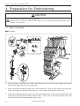
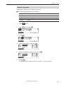
4-1 Upper Threading
■ BES-961BC
1
2
3
Needle Bar No.3,6,9
No.2,5,8
4
No.1,4,7
5
6
7
8
1. Pass the upper thread from the cotton stand through the hole of the thread guide right above
each cotton stand bar from the lower side.
2. Pass the thread through the upper hole of the pretension. Push up the tension disc with your
finger, and place the thread under the disc. Then, pass it through the lower hole.
3. Pass the thread through the upper hole of the 2nd pretension. Push up the tension disc with
your finger, and place the thread under the disc. Then, pass it through the lower hole, and
wind it around the thread breakage pulley twice.
34
BES-961BC • BES-1261BC
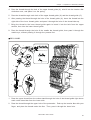
Chapter 1 Preparation of Embroidery Machine
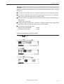
4. Pass the thread through the hole of the upper thread guide (U), wind it into the tension disk
clockwise once, and place it on the spring.
5. Pass the thread through each hole of the upper thread guide (U) and the thread guide (C).
6. After passing the thread through the hole of the thread guide (U), insert the thread into the
right side of the inner thread guide, and pass it through the hole of the thread take-up.
7. Bring the thread to the inner thread guide again to insert it into the hole from the upper
section, then into the lower thread guide.
8. Pass the thread through the hole of the needle bar thread guide, then pass it through the
needle eye, without passing it through the presser foot.
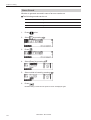
■ BES-1260BC
1
2
3
Needle Bar No.3,6,9,12
No.2,5,8,11
4
No.1,4,7,10
5
6
7
8
1. Pass the upper thread from the cotton stand through the hole of the thread guide right above
each cotton stand bar from the lower side.
2. Pass the thread through the upper hole of the pretension. Push up the tension disc with your
finger, and place the thread under the disc. Then, pass it through the lower hole.
BES-961BC • BES-1261BC
35
Chapter 1 Preparation of Embroidery Machine
3. Pass the thread through the upper hole of the 2nd pretension. Push up the tension disc with
your finger, and place the thread under the disc. Then, pass it through the lower hole, and
wind it around the thread breakage pulley twice.
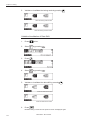
4. Pass the thread through the hole of the upper thread guide (U), wind it into the tension disk
clockwise once, and place it on the spring.
5. Pass the thread through each hole of the upper thread guide (U) and the thread guide (C).
6. After passing the thread through the hole of the thread guide (U), insert the thread into the
right side of the inner thread guide, and pass it through the hole of the thread take-up.
7. Bring the thread to the inner thread guide again to insert it into the hole from the upper
section, then into the lower thread guide.
8. Pass the thread through the hole of the needle bar thread guide, then pass it through the
needle eye, without passing it through the presser foot.
36
BES-961BC • BES-1261BC
Chapter 1 Preparation of Embroidery Machine
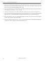
4-2 Replacement of Bobbin
Note) Remove dust, lint and oil from the bobbin case before replacement.
■ Removing bobbin case
1. Open the rotary hook cover B q.
w
2. Hold the knob w and take out the bobbin
case.
3. Close the knob and take out the bobbin e.
q
e
■ Replacing bobbin
1. Put a new bobbin in the bobbin case.
2. Slide the thread under the tension spring
t through the notch r.
Pull out by about
50 mm
3. Pull out the thread from the hole of the
tension spring t.
4. Pull out the thread by about 50 mm.
t
r
■ Attaching bobbin case
w
1. Hold the knob w and attach the bobbin
case securely.
2. Close the rotary hook cover B q.
q
BES-961BC • BES-1261BC
37
Chapter 1 Preparation of Embroidery Machine
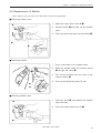
4-3 Replacing and Selecting Needle
■ Removing needle
Loosen the set screw q and remove the needle
q.
■ Attaching needle
q
With the flat side facing the front, insert the
needle all the way until it meets the end of the
needle bar. Tighten the set screw q firmly.
w
Note)
• Set the needle so that the notched part will
come on the rotary hook side.
• The needle should not be angled to the left
(when viewed from the front).
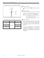
* Relationship between materials and needles
Material
Needle
Denim
Leather
Handkerchief
Shirt
Towel
38
Needle thickness
#14,
#16, #18
DB x K5
#9, #10
#11,
#12, #13
■ Selecting needle
• When using special threads such as gold,
silver, and rame yarn, use a heavy-duty
needle (#11 ~ #16). For better finish, paste
the waxed paper on the back of the
material.
• In general, use DBxK5 #11 ~ #18 according
to the material thickness. For knitted
materials, use DBxK23 #11 because its
rounded point prevents the knit thread from
breaking.
BES-961BC • BES-1261BC
Chapter 1 Preparation of Embroidery Machine
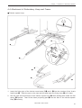
4-4 Attachment of Embroidery Hoop and Frame
■ Tubular square hoop
r
e
w
q
y
u
t
q
1. Insert the fixing pins of the tubular round arms R q and L w into the notches of the X-axis
feed frame e. Slide the arm to the right and left and lower the fixing lever r to fix them.
2. Set the right and left fixtures of the tubular square hoop t while sliding them under the flat
spring y upward. Then fit the frame projecting part u into the hole of the tubular square
hoop t securely.
BES-961BC • BES-1261BC
39
Chapter 1 Preparation of Embroidery Machine
• By changing the tubular round arm mounting width, various sizes can be set.
Note) Change the width, referring to the pin position.
400mm
360mm
600mm
500mm
Note) If two pins cannot be inserted properly, remove one of them.
40
BES-961BC • BES-1261BC
Chapter 1 Preparation of Embroidery Machine
■ Holder base (optional)
w
q
r
i
y
y
e,t
Felt
e
u
Table
y
1mm
r
1mm
t
Attaching the holder base frame
1. Set the table. (Refer to "3-4 Mounting of Table" (Page 26) for details.)
2. Mount the frame connecting plate R w on the X-axis feed frame q, using six bolts, washers,
and nuts.
3. Insert the frame connecting plate y into the holder base frame L e, holder base frame C r,
and holder base frame R t, using bolts and washers.
4. From the front, put the holder base frame C assembly r under the frame connecting plate R
w and fix it using four bolts.
5. Check that the clearance between the table and the mounted holder base frame C assembly
r is even when viewed from the machine front.
[Adjustment]
Loosen three bolts of the F table support F y and move it in the direction of the arrow for adjustment.
BES-961BC • BES-1261BC
41
Chapter 1 Preparation of Embroidery Machine
6. Check that the clearance between the Y-axis cover u and the mounted holder base frames L
e and R t is even when viewed from the right and left sides.
[Adjustment]
Loosen the right and left bolts of the F table guide U i and move it in the direction of arrow for
adjustment.
7. Tighten each bolt securely after adjustment is finished.
Attaching the holder base
1. Mount the holder base mounting frame e on the X-axis feed frame q and holder base frame
C w, using three clamp screws.
2. When the mounting pitch of the holder base is 370 mm, mount the holder base horizontally to
the holder base mounting frames e using the thumb bolts r.
q
r
e
w
42
BES-961BC • BES-1261BC
Chapter 1 Preparation of Embroidery Machine
3. When the mounting pitch of the holder base is 550 mm, mount the holder base vertically to
the X-axis feed frame q and holder base frame C w using the thumb bolts r.
r
q
r
w
BES-961BC • BES-1261BC
43
Chapter 1 Preparation of Embroidery Machine
■ Sash frame (optional)
w
q
q
e
r
y
t
t
y
e
e
Attaching the sash frame
1. Set the table. (Refer to "3-4 Mounting of Table" (Page 26) for details.)
2. Mount two vertical sash frames q on the holder base frames L and R, and two horizontal
sash frames w on the X-axis feed frame e and the holder base frame C r, using the screws.
3. Set the material. Then, set 16 clips 290 y horizontally in two sides and 4 clips 220 y vertically
on the right and left sides.
44
BES-961BC • BES-1261BC
Chapter 1 Preparation of Embroidery Machine
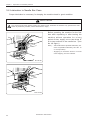
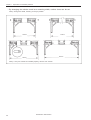
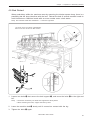
4-5 Bed Retract
When embroidery within the maximum area by mounting the tubular square hoop, there is a
possibility that the hoop interferes with the bed. Retract the bed of several machine heads to
avoid interference. Machine heads with an even number enter a halt status.
Note) The machine heads are numbered 1 ~ 6 from the right side.
This figure shows an example of BES-961BC.
Refer to the same sections for BES-1261BC.
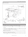
q
e
w
No.6
No.4
No.2
r
1. Loosen two bolts w that secure the bed support q, and move the bolts w to the right and
left.
Note)
• The bed is secured by two bolts and supported at three places.
• When loosening the bolts, support the bed by hand.
2. Lower the machine bed e slowly until it comes into contact with the leg.
3. Tighten the bolts w again.
BES-961BC • BES-1261BC
45
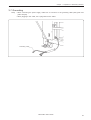
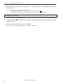
Chapter 1 Preparation of Embroidery Machine
4. Set the needle bar case at the needle bar No. 1. Remove the presser foot r from the retracted
machine bed.
Note)
• The head of the retracted bed is stopped.
• When removing the presser foot, align the pulley indication mark 3 first.
• To operate the machine in retract position, set the bed in contact with the legs.
Resetting of bed retract
1. Move the machine bed e little by little until it comes into contact with the bed support q.
2. Loosen two bolts w and insert the bed into the right and left directions, then tighten the bolts
securely again.
3. Mount the presser foot for the reset bed e.
(Refer to "Chapter 8. Standard Adjustment" for mounting the presser foot.)
46
BES-961BC • BES-1261BC
Chapter 1 Preparation of Embroidery Machine
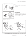
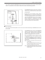
4-6 Adjustment of Thread Tension
■ Adjustment of upper thread
Adjust upper thread tension to 0.7~1.3N (70~130
gf) when the thread is pulled at the needle bar
thread guide.
0.7~1.3N
(70~130gf)
* Correct adjustment
Upper stitch
width
Turn the upper thread tension dial so that the
needle thread can be pulled to the back of the
material and that the lower stitch width will be
about 1/3 of the upper stitch width.
Upper
thread
Lower
thread
Lower
stitch
width
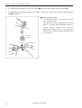
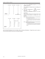
■ Adjustment of tension spring
q
w
e
6~8mm
0.07~0.12N
(7~12gf)
1. The tension spring should be adjusted to 6~8 mm in height and 0.07~0.12 N (7~12 gf) in force.
BES-961BC • BES-1261BC
47
Chapter 1 Preparation of Embroidery Machine
2. For adjusting the height, loosen the screw q and turn the tension spring bracket w.
3. For adjusting the tension spring force, insert a driver tip in the groove of the thread tension
bar e and turn it.
■ Lower thread tension
The standard tension of the lower thread is
0.15~ 0.3N (15~30gf).
This tension may vary depending on the used
thread. In general, press the bobbin case to a
smooth vertical surface and hang the
designated number of coins. Turn the thread
tension screw so that the lower thread will come
out smoothly.
0.15~0.3N
(15~30gf)
To tighten
To loosen
48
BES-961BC • BES-1261BC
Chapter 2
Embroidering Procedures
After installation of machine start embroidering. This chapter explains about the operation panel on the machine as well as precautions for the actual embroidering process.
Chapter 2 Embroidering Procedures
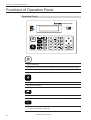
Functions of Operation Panel
Operation Panel
BES-961BC
FLAT
CAP
HOOP
ESC
START
INS
DEL
END
STOP
.
2
3
ABC
DEF
4
5
6
GHI
JKL
MNO
1
7
8
9
PQRS
TUV
WXYZ
0
SPACE
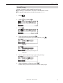
START
Starts embroidering.
Restarts after moving the carriage to embroidering start position by using the jog switch.
Restarts embroidering after a suspension.
STOP
Cancels errors during embroidering.
Suspends embroidering.
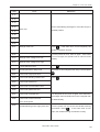
Selects sewing data. (→ "Chapter 3 Selection of Data and Embroidering" page 59)
Specifies a sequence of colors (sequence of needle changes) in sewing data.
(→ "Setting of Needle Bars" page 92)
50
BES-961BC • BES-1261BC
Chapter 2 Embroidering Procedures
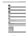
Edits sewing data. (→ "Chapter 4 Editing of Embroidering Data" page 77)
Sets the upper thread breakage sensor. (→ "Thread Breakage Sensor" page 93)
Machine motions can be set. (→ "Chapter 5 Setting" page 89)
Trims thread during suspension.
Moves the hoop to a preset hoop retract position. When this switch is pressed again, the
hoop returns to the previous position.
Checks the embroidering area.
Moves the hoop automatically into the embroidering area when the embroidery position
is out of the area.
ESC
INS
DEL
END
.
2
3
ABC
DEF
4
5
6
GHI
JKL
MNO
1
7
8
9
PQRS
TUV
WXYZ
0
SPACE
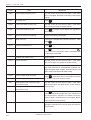
Used for selecting data and setting functions.
BES-961BC • BES-1261BC
51
Chapter 2 Embroidering Procedures
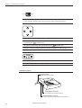
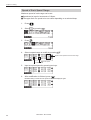
FLAT
CAP
HOOP
Selects the flat or cap hoop. This selection should be done before turning the power ON
to the machine. Selection after turning the power ON may damage the hoop.
Moves the hoop.
Step-back or forward is available during suspension, by one stitch every time the switch
is pressed (Use
switches only.)
Changes the speed range during embroidering (Use
switches only).
Carries out inching of the hoop when the switch is pressed in the inching mode
Move the cursor for selecting sewing data and an icon.
Moves the needle bar. The needle moves by the diameter every time this switch is pressed.
Change to the screen for selecting sewing data.
Operation panel
Contrast volume
Adjusts the screen contrast.
SBUS interface connector
Not used (Do not connects anything.)
RS-232C interface connector
Connect personal computer with BE-100 installed, etc.
52
BES-961BC • BES-1261BC
Chapter 2 Embroidering Procedures
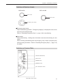
Switches at Machine Heads
BES-961BC
BES-1261BC
Start button
Start button
Emergency stop button
■ Emergency stop button
Stops embroidering operation. "Emergency stopping" is displayed on the screen
as soon as the machine stops.
Refer to "Resetting Emergency Stop" (→ page 119) to stop flashing.
■ Start button
Starts embroidering. Holding down this button executes embroidering at a low
speed.
When resuming embroidering after an emergency stop, release emergency stop
before pressing this button. Refer to "Resetting Emergency Stop" (→ page 119)
for details.
Switches on Tension Plate
THREAD SENSOR lamp
HEAD switch
MENDING lamp
MENDING switch
STEP BACK/FWD switch
BES-961BC • BES-1261BC
53
Chapter 2 Embroidering Procedures
■ THREAD SENSOR lamp
When red light is on, thread breakage sensor is functioning. When the light is off,
the sensor is not effective. When the embroidery machine stops due to thread
breakage, the lamp flashes.
■ HEAD switch
When it is set to ON, needle bar on the head moves for embroidering. When it is
set to OFF, the needle bar does not move for embroidering.
■ MENDING lamp
This lamp lights up when the embroidery machine is in the mending mode.
A lamp on the head with an error lights up. (only when the error can be located)
■ MENDING switch
This switch is set to upside to drive or to suspend the machine head during
embroidering for a designated period of time.
■ STEP BACK/FWD switch
When it is turned to BACK, the machine steps back. When it is turned to FWD,
the machine steps forward. If you keep the switch turned for a while, the machine
will continue stepping even after you let the switch alone. When it is turned to the
opposite side, the machine stops.
During timing adjustment of the rotary hook in the test mode, the rotary hook
slightly rotates to the left/right when this switch is turned to left/right respectively.
Refer to "Adjustment of timing Between Needle and Rotary Hook" (→ page 144)
for further details.
If any error occurs, it can be reset.
54
BES-961BC • BES-1261BC
Chapter 2 Embroidering Procedures
Flowchart of Preparation for Embroidering
Turn on the machine power. (→ page 56).
▼
Retrieve the embroidery data (→ page 57).
"Chapter 3 Selection of Data and Embroidering" (→ page 59)
Edit the retrieved embroidery data.
▼
"Chapter 4 Editing of Embroidering Data" (→ page 77)
on the operation panel.
Press
▼
Press
START
on the operation panel.
BES-961BC • BES-1261BC
55
Chapter 2 Embroidering Procedures
Turn on the Machine Power
1.
Turn on the power to the machine.
2.
A message is displayed on the LCD as soon as the power is turned ON.
BES-961BC
BES-1261BC
3.
The alarm sounds three times. The needle bar and the presser foot move up.
The hoop moves back to the zero point and the sewing screen is displayed.
The speed range and actual speed is displayed.
A sequence of changing colors is displayed.
A sequence of colors is displayed.
A total number of stitches is displayed.
A data name is displayed.
A number of colors registered in data is displayed.
A kind of hoop is displayed.
Operational icons are basically displayed; however, some icons,
such as
, may not be on the screen.
START
56
STOP
BES-961BC • BES-1261BC
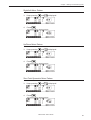
Chapter 2 Embroidering Procedures
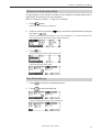
Retrieve the Embroidery Data
The description in this section is based on the method of reading data which is
registered in the memory unit of the machine.
Refer to "Selection of Data" (→ Page 61) for details.
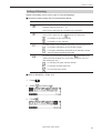
1.
Press
switch.
Data saved in the machine is displayed.
2.
Select a screen by pressing
ten keys or
keys, and select required data by pressing
.
When using ten keys for data selection, input a numerical figure (1 ~ 9) which indicates each
data name. Required embroidery data is selected and read.
3.
Press
key.
Required embroidery data is selected and read.
Selected embroidery data is read.
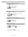
Start Embroidering
1.
Press
2.
Press
to check the embroidering area.
START
to start embroidering.
Sewing is started and the next screen is displayed.
BES-961BC • BES-1261BC
57
Chapter 2 Embroidering Procedures
58
BES-961BC • BES-1261BC
Chapter 3
Selection of Data and Embroidering
This Chapter describes how to select embroidery data in order to start embroidering.
Chapter 3 Selection of Data and Embroidering
What Can the Machine Do?
Selection of Embroidery Data
Registration of data from the floppy disk (→ Page 61)
Reading of data from the memory (→ Page 64)
Registration of data created by BE-100 (→ Page 65)
(These icons are displayed in the lower right of the screen.)
Modification of data name (→ Page 68)
Deletion of embroidery data (→ Page 66)
Embroidering Operation
Embroidering start (→ Page 72)
Embroidering feedhold (→ Page 73)
Embroidering cancel (→ Page 73)
Step forward/step back (→ Page 74)
Step forward (back) stitch by stitch
Step forward (back) by every 10 stitches
Step forward (back) by every 100 stitches
Step forward (back) until a next color change
Step forward (back) to the embroidering start point
of a next pattern
Step forward (back) by a specified number of
stitches (→ Page 74)
60
BES-961BC • BES-1261BC
Chapter 3 Selection of Data and Embroidering
Selection of Data
Select data in order to start sewing.
■ Data to use for actual embroidering is selected from data registered in the machine
memory. A maximum of 45 kinds or 480,000 stitches of embroidery data can be
registered in the machine memory; however, depending on the combination of
embroidery data, the number of total stitches available may become less.
■ When using data in a floppy disk or in BE-100, register it in the machine memory
once before selection.
If there is no space in the machine memory, delete unnecessary data to make a
space.
Data in a floppy disk
Machine memory
Registration
Data created by BE-100
Reading
Sewing
Registration of Embroidery Data from Floppy Disk
Register embroidery data from a floppy disk into the machine memory.
■ Types of data to be registered are as shown below.
• DOS-formatted data
Data format
Extension
ECS
Data with a name of [xxxx.ECS]
Tajima
Data with a name of [xxxx.DST]
Barudan
Data with a name of [xxxx.DSB]
Zanks (DSK)
Data with a name of [xxxx.DSZ]
Data received from BE-100
Data with a name of [xxxx.STH]
Icon
(These icons are displayed in the lower right of the screen.)
BES-961BC • BES-1261BC
61
Chapter 3 Selection of Data and Embroidering
• Other data
Data format
Icon
Barudan FDR
Barudan FMC
(These icons are displayed in the lower right of the screen.)
Loading and Loading of Floppy Disk
1.
When loading a floppy disk, set it straight with the labeled surface facing this
side.
2.
When unloading a floppy disk, press the eject switch.
3.
When it comes out, pull it straight.
When the access lamp if ON, never press the eject switch. Otherwise, embroidery data in the
floppy disk may be destroyed.
Eject switch
Access lamp
Registration of Sewing Data into Machine Memory
1.
62
Load a floppy disk with sewing data.
BES-961BC • BES-1261BC
Chapter 3 Selection of Data and Embroidering
2.
Press
.
3.
Select a screen for data registration by pressing
.
Currently displayed screen
No. of screens to be selected
Data in machine memory
Currently selected embroidery data
Number of stitches in selected embroidery data
When there is no data
4.
Select an area for registration, using ten keys or
, then press
.
A space available is automatically selected.
Pressing
automatically locates the first space in the memory.
5.
Data in the floppy disk is displayed. Press
to select a screen.
Currently displayed screen
No. of screens to be selected
Data in floppy disk
Icon indicating a kind of selected data
Pressing
displays a pattern name.
Name of a selected embroidery pattern
(It may be the same as a file name.)
6.
Select data to register by pressing ten keys or
then press
.
Data is newly registered in the machine memory.
Select embroidery data and press
START
. The selected data is automatically registered in the
memory and the machine enters a standby status.
If registration is done without loading a floppy disk, the following screen is displayed after the
step 4 is finished.
Load a floppy disk for data registration.
BES-961BC • BES-1261BC
63
Chapter 3 Selection of Data and Embroidering
Reading from Memory
Data to use for sewing can be selected from the machine memory.
■ A maximum 45 kinds or 480,000 stitches of embroidery data can be registered in
the memory.
1.
Press
.
Embroidery data registered in the memory is displayed.
2.
Select a screen by pressing
.
Currently displayed screen
No. of screens to be selected
3.
Select embroidery data to read by pressing ten keys or
4.
Press
.
.
Embroidery data is selected and read.
When a free space is specified in the memory, a screen for reading data from the floppy disk is
displayed.
Refer to "Registration of Sewing Data into Machine Memory" (steps 5 and afterward on Page
63).
5.
64
The initial screen is displayed.
BES-961BC • BES-1261BC
Chapter 3 Selection of Data and Embroidering
Registration of Embroidery Data from BE-100
Connect the operation panel and the personal computer with BE-100 installed in
order to register the embroidery data into the machine memory.
1.
Connect the personal computer with BE-100 installed and the operation panel
by means of the RS-232C cable.
Personal computer with BE-100 installed
Operation panel
Dedicated communication cable (Option)
2.
Press the
3.
Select the data registration screen by pressing the
4.
Select an area for data registration by pressing ten keys or
5.
.
press the
key.
Press the
.
.
, and then
When a floppy disk is set
When no floppy disk is set
BES-961BC • BES-1261BC
65
Chapter 3 Selection of Data and Embroidering
6.
Press the
.
↓
7.
The BE-100 embroidery data is displayed. Press the
and select a required
screen.
8.
Select embroidery data to register by pressing ten keys or
, and then
key.
press the
The data is registered in the machine memory.
Deletion of Embroidery Data from Machine Memory
Embroidery data can be deleted from the machine memory.
1.
Press
.
A list of registered data is displayed.
2.
Select a screen by pressing
.
Currently displayed screen
No. of screens to be selected
3.
66
Select embroidery data to delete by pressing ten keys or
BES-961BC • BES-1261BC
.
Chapter 3 Selection of Data and Embroidering
4.
Press
DEL
.
Selected embroidery data is deleted from the memory.
↓
When deleting embroidery data in the machine memory entirely:
When deleting embroidery data registered in the machine memory entirely, turn
ON the power to the machine while pressing D E L .
BES-961BC • BES-1261BC
67
Chapter 3 Selection of Data and Embroidering
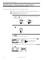
Modification of Embroidery Data Name
Name of embroidery data registered in the machine memory can be modified.
This example shows how to modify the data name "FLOWER" to "TEST003".
■ A maximum number of characters to use for an embroidery data name is 8.
■ The following kinds of characters can be used.
■ It is impossible to input a " . " or space.
Alphabetical characters (A ~ Z) Numerical characters (0 ~ 9)
0 through 9 . An input character changes depending on the number of times
Use SPACE
WXYZ
each is pressed as shown below.
5
1 time
JKL
4 times
3 times
2 times
7
1 time
PQRS
5 times
4 times
3 times
2 times
_ (underbar), - (hyphen)
Use 1 . .
1
.
3 times
2 times
1.
Press
.
Embroidery data saved in the memory is displayed.
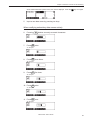
2.
A list of embroidery data is displayed. Select a screen by pressing
.
Currently displayed screen
No. of screens to be selected
68
3.
Select embroidery data to modify the name by pressing ten keys or
4.
Press
.
BES-961BC • BES-1261BC
.
Chapter 3 Selection of Data and Embroidering
When selected data has a pattern name, the name is displayed. Press the
5.
key once again.
Input a new data name by pressing ten keys.
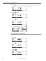
When modifying embroidery data names entirely
6.
Pressing
7.
Press
8
TUV
DEL
deletes currently reversed characters.
twice.
"T" is input.
8.
Press
3
DEF
three times.
"E" is input.
9.
Press
7
PQRS
five times.
"S" is input.
10. Press
8
TUV
twice.
"T" is input.
11. Press
0
SPACE
once.
"0" is input.
BES-961BC • BES-1261BC
69
Chapter 3 Selection of Data and Embroidering
12. Press .
When inputting the same character continuously, press the
13. Press
0
to move the cursor to the right.
once.
SPACE
"0" is input.
14. Press
3
once.
DEF
"3" is input.
15. After inputting a data name, press
.
A data name is modified by the above procedures.
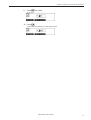
When modifying only one character:
[FLNWER] can be modified to [FLOWER] in the following procedures.
6. Press
.
7.
Press
twice and display "N" reversely.
8.
Press
DEL
.
"N" is deleted.
70
BES-961BC • BES-1261BC
Chapter 3 Selection of Data and Embroidering
9.
Press
6
MNO
four times.
"O" is input.
10. Press
.
A data name is modified by the above procedures.
BES-961BC • BES-1261BC
71
Chapter 3 Selection of Data and Embroidering
Sewing Operation
Before Starting Sewing
Select a hoop to set on the machine.
■ The following operation should be done before turning the power ON to the
machine. Otherwise, it will damage the hoop.
1.
Select either the flat hoop or cap hoop, using FLAT or CAP switch on the
operation panel.
When a flat or tabular hoop , or a sash frame is set on the machine, select [FLAT].
When a cap hoop is set, select [CAP].
FLAT
CAP
HOOP
2.
Specify an embroidery hoop set on the machine, referring to "Embroidery Hoop"
(→ Page 96).
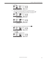
Starting Sewing Operation
■ For details of specifying a sewing start position, refer to "Registration of Sewing
Start Position" (→ Page 104).
■ When
is pressed while the message "Area over" is indicated on the screen,
a dialog box is displayed for confirming whether or not to start sewing forcibly.
Pressing
starts sewing; however, depending on the start position, an
interference with the frame may occur. Exercise added care when doing so.
START
1.
Check that sewing data has been selected, then press
START
.
Sewing is started.
The current embroidering status is indicated.
Indicates a sequence of color changes.
No. of current stitches
Indicates a name of data currently used for sewing.
Indicates the number of data currently used for sewing.
Currently selected speed range
The range can be modified by pressing
72
BES-961BC • BES-1261BC
.
Chapter 3 Selection of Data and Embroidering
Feedhold and Cancellation of Sewing
Feedhold
1.
Press
STOP
.
Sewing is interrupted.
Cancellation
1.
Press
ESC
while sewing is interrupted.
When repetition of patterns is set, a pattern which is currently being sewn is canceled. When
canceling all patterns, press ESC once again.
2.
A message for confirmation is displayed. When canceling sewing, press
BES-961BC • BES-1261BC
.
73
Chapter 3 Selection of Data and Embroidering
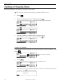
Step Forward and Step-Back
Stitches can be advanced (step forward) or retracted (step-back) without sewing.
Step Forward/Step-Back Mode
1.
Press
when selecting either mode before starting sewing and press
STOP
when selecting a mode during sewing.
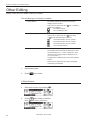
Setting Amount or Timing of Step Forward/Step-Back
A step forward/step-back amount or timing can be selected as described below.
For stepping forward (back) stitch by stitch
For stepping forward (back) by 10 stitches
For stepping forward (back) by 100 stitches
For stepping forward (back) up to the next (previous) color change
For stepping forward up to the sewing start point of a next pattern if
repetition of patterns is set.
Specify the number of stitches for stepping forward (back).
1.
Select a required item as described above by pressing
.
When the number of stitches is specified, the needle steps forward (back) to
an input position:
1.
Press the
five times.
2.
Input the number of stitches to move by pressing ten keys.
3.
Press the
END
.
The needle steps forward (back) as specified.
74
BES-961BC • BES-1261BC
Chapter 3 Selection of Data and Embroidering
4.
The embroidery head advances (retracts) by a specified number of stitches.
For Step Forward (Back)
1.
Press
.
Stitches steps forward (back) by a specified amount.
Resuming Sewing
1.
Press
START
.
Sewing is started.
BES-961BC • BES-1261BC
75
Chapter 3 Selection of Data and Embroidering
76
BES-961BC • BES-1261BC
Chapter 4
Editing of Embroidering Data
Pressing
on the operation panel after
reading embroidering data displays the embroidering data editing screen. Simple operation by using embroidering data is available on this screen.
Chapter 4 Editing of Embroidering Data
What Can the Machine Do?
Editing
■ Enlargement/reduction is executed ahead of rotation. When an embroidery
pattern is so set to be rotated by 90˚ and then enlarged by 2 times in the X-axis
direction, the X-axis enlargement is executed first and rotation by 90˚ is executed
afterwards. Therefore, a pattern is enlarged by 2 times at the sewing point.
Rotation of embroidery pattern (→ Page 79)
Enlargement/reduction of embroidery pattern in the X-axis direction
(→ Page 80)
Enlargement/reduction of embroidery pattern in the Y-axis direction
(→ Page 80)
Mirror pattern (→ Page 82)
Right/left mirror pattern
Up/down mirror pattern
Zero point symmetric mirror pattern
No. of repetitions in the horizontal direction (lines) (→ Page 84)
No. of repetitions in the vertical direction (rows) (→ Page 84)
(
)
Distance in the horizontal direction between two outer hoop
centers (→ Page 84)
(
)
Distance in the vertical direction between two outer hoop
centers (→ Page 84)
Direction of repetitions (→ Page 84)
Horizontal direction from upper left to lower right
Vertical direction from upper right to lower left
Horizontal direction from lower right to upper left
Vertical direction from lower left to upper right
Horizontal direction from upper right to lower left
Vertical direction from upper left to lower right
Horizontal direction from lower left to upper right
Vertical direction from lower right to upper left
0 stitch deletion (→ Page 86)
Thread trimming feed number (→ Page 87)
Swing width correction (→ Page 87)
78
BES-961BC • BES-1261BC
Chapter 4 Editing of Embroidering Data
Rotation
A pattern can be rotated.
→ ■ A maximum range of rotation is 1 ~ 359 degrees.
■ The rotating direction is counterclockwise.
■ Rotating angle can be set in either of the following.
By using
Angle can be specified in increments of 90˚. Setting of 90˚,180˚
or 270˚ is available.
By using ten keys
Angle can be specified in increments of one degree.
1.
Read sewing data.
2.
Press
3.
Press
4.
Press
.
to select an angle or use ten keys to specify an angle.
END
.
The initial screen is displayed again.
BES-961BC • BES-1261BC
79
Chapter 4 Editing of Embroidering Data
Enlargement and Reduction
A pattern can be enlarged or reduced.
→ →
■ The enlargement and reduction ratio is 50 ~ 200%.
■ The number of stitches does not change even by enlargement or reduction of a
pattern. However, stitches may become too rough or close if enlargement or
reduction is excessive.
■ There are the following two types of enlargement/reduction.
• Enlargement/reduction at the same ratio in both the X and Y directions
• Enlargement/reduction at different ratios in the X and Y directions
1.
Read sewing data.
2.
Press
.
Enlargement/reduction at the same ratio in the X/Y directions
3.
Press
.
are reversed in black.
4.
Input enlargement/reduction ratio by pressing ten keys.
5.
Press
END
.
The initial screen is displayed again.
80
BES-961BC • BES-1261BC
Chapter 4 Editing of Embroidering Data
Enlargement/reduction at different ratios in the X/Y directions
3.
Press
twice.
is reversed in black.
4.
Input enlargement/reduction ratio in the X direction by pressing ten keys.
5.
Press
.
is reversed in black.
6.
Input enlargement/reduction ratio in the Y direction by pressing ten keys.
7.
Press
END
.
The initial screen is displayed again.
BES-961BC • BES-1261BC
81
Chapter 4 Editing of Embroidering Data
Mirror
A pattern can be reversed as if it is reflected in the mirror.
→ Right/left mirror patter
→ Up/down mirror patter
→ Zero point-symmetric mirror patter
■ Up/down mirror pattern → Right/left mirror pattern → Zero point-symmetric mirror
pattern.
82
Right/left mirror pattern
The pattern is reversed in the right/left
direction on the basis of the embroidering
start point.
Up/down mirror pattern
The pattern is reversed in the up/down
direction on the basis of the embroidering
start point.
Zero point-symmetric mirror pattern
The pattern is reversed on the basis of
the embroidering start point.
1.
Sewing data is read.
2.
Press
.
BES-961BC • BES-1261BC
Chapter 4 Editing of Embroidering Data
Right/Left Mirror Pattern
3.
Keep pressing
4.
Press
END
until
is displayed.
.
The initial screen is displayed again.
Up/Down Mirror Pattern
3.
Keep pressing
4.
Press
END
until
is displayed.
.
The initial screen is displayed again.
Zero Point-Symmetric Mirror Pattern
3.
Keep pressing
4.
Press
END
until
is displayed.
.
The initial screen is displayed again.
BES-961BC • BES-1261BC
83
Chapter 4 Editing of Embroidering Data
Repetition
A pattern is repeatedly copied as many times as specified.
→
■ The number of repetitions is 1 ~ 99 in both the vertical (row) and horizontal (line)
directions.
■ There are the following eight directions of repetitions.
Horizontal direction from upper left to lower right
Vertical direction from upper right to lower left
Horizontal direction from lower right to upper left
Vertical direction from lower right to upper left
Vertical direction from lower left to upper right
Horizontal direction from upper right to lower left
Vertical direction from upper left to lower right
Horizontal direction from lower left to upper right
■ There are the following two types of intervals between repetitions.
By setting a distance between the outer hoops of each pattern
By setting a distance between the centers of each pattern
1.
Read sewing data.
2.
Press
3.
Input the number of repetitions in the vertical and horizontal directions, by
pressing ten keys.
twice.
The vertical and horizontal directions are changed over by pressing
84
BES-961BC • BES-1261BC
.
Chapter 4 Editing of Embroidering Data
4.
5.
Press
.
Input intervals between repetitions by pressing ten keys.
The vertical and horizontal directions are changed over by pressing
Press
for setting a distance between the centers of each pattern.
.
For setting a distance between the outer
hoops of each pattern
For setting a distance between the centers
of each pattern
6.
Select the direction of repetitions by pressing
7.
Press
END
.
.
The initial screen is displayed again.
BES-961BC • BES-1261BC
85
Chapter 4 Editing of Embroidering Data
Other Editing
Setting of other functions related to editing is available.
The following types of setting is available.
0 stitch deletion
For deleting stitches at the same point without
stepping forward or back.
This function is previously set to
(for not deleting
0stitch)upon shipment.
For deleting 0 stitch
For not deleting 0 stitch
Thread trimming feed number
For setting the number of feeds for thread trimming
This function is previously set to
(ECS data)
or
(Except ECS data)upon shipment.
For thread trimming at every 3 feeds
For thread trimming at every 5 feeds
For thread trimming at every 8 feeds
For not thread trimming
Swing width correction
1.
Read sewing data.
2.
Press
For setting the needle swing width correction amount
The correction amount can be set in increments of 0.1mm.
The setting range is 0 ~ 1.0mm in both the X and Y
directions. (The setting range is displayed as "0 ~
10" on the screen.)
Compensation is reflected only on the satin-stitched
section.
This function is previously set to 0(no swing width
correction)upon shipment.
three times.
0 Stitch Deletion
3.
Select this function by pressing
4.
Press
Press
86
END
after setting is finished.
when setting continuously.
BES-961BC • BES-1261BC
.
Chapter 4 Editing of Embroidering Data
Thread Trimming Feed Number
3.
Select this function by pressing
4.
Select the number of feeds by pressing
5.
Press
END
.
.
after setting is finished.
Swing Width Correction
Correction values within 1 ~ 10 can be input. However, excessively large values
may result in distortion of a pattern.
3.
Select this function by pressing
4.
Select a correction amount in the X direction by pressing
5.
Reverse
6.
Input a correction amount in the Y direction by pressing
by pressing
.
.
.
BES-961BC • BES-1261BC
.
87
Chapter 4 Editing of Embroidering Data
7.
Press
Press
88
END
after setting is finished.
when setting continuously.
BES-961BC • BES-1261BC
Chapter 5 Setting
This Chapter describes how to set a sewing
speed, correct trouble including thread breakage and others related to machine motions.
Chapter 5 Setting
What Can the Machine Do?
Setting of Needle Bars
Needle bars allocated in the sequence of embroidering (→ Page 92)
Setting of Thread Breakage Sensor
Thread breakage sensor ON/OFF (→ Page 93)
Thread breakage sensitivity (→ Page 93)
Number of stitches in automatic step back (→ Page 94)
Display of total stitch number in automatic step back
Lower thread counter counts (→ Page 95)
Stitch counter indication (→ Page 95)
Setting of Machine
Selection of embroidery hoop (→ Page 96)
Display of every head/every other head (→ Page 96)
Speed range (→ Page 97)
Speed in speed range (→ Page 98)
Thread trimming length (→ Page 101)
Thread removal feed length (→ Page 101)
Inching ON/OFF (→ Page 102)
Sewing area (→ Page 103)
Resetting of thread breakage error (→ Page 100)
Needle bar stop at mending stop point (→ Page 100)
Method of thread trimming before thread breakage error (→ Page 100)
Method of thread trimming before stop (→ Page 100)
90
BES-961BC • BES-1261BC
Chapter 5 Setting
Setting of Environment
Return to start point after embroidering end (→ Page 106)
Method of reflecting modified machine speed (→ Page 107)
Power voltage (→ Page 107)
Data transfer speed (→ Page 108)
Display language (→ Page 109)
Alarm sound (→ Page 110)
Boring mode ON/OFF (→ Page 111)
Data shift ON/OFF (→ Page 112)
Display of Information
Display of pattern information (→ Page 113)
Features of machine (→ Page 114)
Version information (→ Page 115)
Hoop Retract Point
Hoop retract point (→ Page 104)
Automatic hoop retract ON/OFF (→ Page 105)
Hoop Movement
Registration of embroidering start point (→ Page 104)
Movement to registered sewing start point (→ Page 105)
BES-961BC • BES-1261BC
91
Chapter 5 Setting
Setting of Needle Bars
Needle bars allocated in the sequence of sewing can be modified.
■ This setting is explained on the basis of the BES-1261BC screen.
1.
2.
Press
.
Select a sewing sequence to modify by pressing
.
The current embroidering sequence is selected while embroidering is interrupted.
Press
3.
for modifying all sequences at one time.
Input the number of a needle bar by pressing ten keys.
When inputting a numerical figure exceeding 10, press the 0 first.
SPACE
Insertion of Feedhold
Press
press
and reverse the display on the right of a point to insert a feedhold, then
STOP
.
A feedhold mark is displayed.
4.
Press
END
.
Modified setting is saved and the previous screen is displayed again.
When all sequences are modified at the same time, the screen for checking if the setting needs
to be saved. Press
for saving the setting.
92
BES-961BC • BES-1261BC
Chapter 5 Setting
Thread Breakage Sensor
Validity or invalidity and sensitivity of the thread breakage sensor can be set.
Setting of sensor validity/invalidity
■ This function is previously set to valid for all heads upon shipment.
1.
Press
2.
Specify the number of a machine head by pressing ten keys and validate or
.
invalidate the thread breakage sensor.
Pressing the same ten key once again changes between validity and invalidity.
Heads with which the sensor is valid
Press
3.
Press
to switch over the thread breakage sensor for each head between ON and OFF.
END
.
Modified setting is saved and the initial screen or halt screen is displayed again.
Thread Breakage Sensitivity
Sensitivity of the thread breakage sensor can be set.
■ The sensitivity can be set within the range of 1 ~ 100. Sensitivity increases as
the figure decreases.
■ This function is previously set to 10 upon shipments.
1.
2.
Press
twice.
Select the needle bar for which the sensitivity is modified by pressing
.
The number of needle bars changes in the sequence of :
ALL (all needle bars) → 1 → 2 → ... 9 or 12 (max.) → ALL → ...
3.
Select
by pressing
.
BES-961BC • BES-1261BC
93
Chapter 5 Setting
4.
Input sensitivity of the thread breakage sensor.
5.
Press
END
.
Modified setting is saved and the previous screen is displayed again.
Automatic Step-Back
The number of stitches to step back automatically in case of a thread breakage can
be set.
■ Setting can be done within the range of 0 ~ 10 stitches.
■ This function is previously set to 0 stitches upon shipments.
1.
Press
2.
Select
3.
Input the number of stitches to step back automatically by pressing ten keys.
twice.
by pressing
.
Pressing
sets whether to execute an extra step-back by a sensitivity amount of the thread
breakage sensor in the automatic step-back mode.
Total number of stitches to step back in
the automatic step-back mode
When stepping back by a sensitivity
amount of the thread breakage sensor
When stepping back by preset number of
stitches
4.
Press
END
.
Modified setting is saved and the previous screen is displayed again.
94
BES-961BC • BES-1261BC
Chapter 5 Setting
Setting of Lower Thread Counter/Stitch Counter
■ The lower thread counter reduces the indication each time one pattern is finished.
After the reduction is finished, an error message can be displayed.
■ The stitch counter increases the indication stitch by stitch.
■ The lower thread counter can be validated or invalidated by pressing
.
■ The stitch counter can be cleared to zero by pressing
DEL
.
three times.
1.
Press
2.
Input the number of counts of the lower thread counter by pressing ten keys.
Number of stitches
3.
Press
END
.
Modified setting is saved and the initial screen or halt screen is displayed again.
BES-961BC • BES-1261BC
95
Chapter 5 Setting
Setting of Machine
Machine motions can be set.
Embroidery Hoop
Specify a type of an embroidery hoop set on the machine.
■ A type of a hoop to be selected varies depending on a type of a hoop (flat or cap)
selected by a switch on the operation panel.
When a flat hoop is selected
Tabular square hoop
Sash frame
Flat hoop
When a cap hoop is selected
Cap hoop
■ All heads or every other head can be selected by pressing
.
All heads
Every other head (The heads with odd numbers only are operated).
■ When operating every other head, refer to "Bed Retract" (→ Page 45) and retract
heads with even numbers.
1.
Press
2.
Select
3.
Press
4.
Select a type of a hoop by pressing
.
by pressing
.
.
.
All heads or every other head as
currently selected
Currently selected hoop
5.
Select either all heads or every other head by pressing
6.
Press
END
.
Modified setting is saved and the previous screen is displayed again.
96
BES-961BC • BES-1261BC
.
Chapter 5 Setting
Speed Range
A range of speed for each needle bar can be set.
■ This setting is explained on the basis of the BES-961 screen.
■ The speed range can be set within the range of 1 ~ 6.
1.
Press
2.
Select
3.
Press
4.
.
by pressing
.
.
Select a needle bar by pressing
.
When setting the same speed range for all needle bars, press
.
When modifying the speed range for one
needle bar
When modifying the speed range for all
needle bars
5.
Input a required speed range by pressing ten keys.
6.
After modification is finished, press
END
.
Modified setting is saved and the previous screen is displayed again.
BES-961BC • BES-1261BC
97
Chapter 5 Setting
Speed of Each Speed Range
Maximum speed of each range can be set.
■ Speed can be input in increments of 10spm.
■ The upper limit of a speed to be set varies depending on a selected hoop.
1.
Press
2.
Select
3.
Press
4.
Select a speed range to modify by pressing
.
by pressing
.
.
.
Upper limit of speed to be set in each range
Maximum speed
Lowest speed
5.
Input a required speed by pressing ten keys.
6.
After modification is finished, press
END
.
Modified setting is saved and the previous screen is displayed again.
98
BES-961BC • BES-1261BC
Chapter 5 Setting
Setting of Mending
Details of mending can be set in case of a thread breakage.
■ Contents of each setting item are as described below.
Item
Contents
For setting a mending end point (number of stitches before a thread
breakage) within the range of 1 ~ 10.
This function is previously set to 5 stitches upon shipments.
For setting whether to reset a thread breakage error automatically
This function is previously set to
(Manual) upon shipments.
For resetting an error automatically
For resetting an error manually
For setting whether to stop embroidering temporarily at the mending end point
For stopping embroidering at the mending end point
For stopping embroidering temporarily at the mending end point
and then starting all heads automatically
For setting a thread trimming method using the
immediately after
resetting a thread breakage error. (This setting is effective only once
after resetting the error.)
For trimming both upper and lower threads
For trimming the lower thread only
For not trimming any thread
■ Refer to "Mending"(→Page 121).
1.
Press
2.
Select
by pressing
3.
Press
.
.
.
BES-961BC • BES-1261BC
99
Chapter 5 Setting
Setting of thread breakage error resetting method
4.
Select
by pressing
.
5.
Press
for modifying a resetting method.
For setting whether to stop embroidering temporarily at the mending stop
point
4.
Select
by pressing
.
5.
Press
and select whether to stop embroidering temporarily.
Setting of thread trimming method after stopping
4.
Select a stop point (number of stitches before a thread breakage) by pressing
ten keys.
Setting of mending stop position
4.
Select a stop point (number of stitches before mending) by pressing ten keys.
The machine does not stop if the automatic step-back setting is lower than the input value.
Modify this figure.
After setting all items, press
END
.
Modified setting is saved and the initial screen is displayed again.
100
BES-961BC • BES-1261BC
Chapter 5 Setting
Thread Trimming Length
Length of thread to leave on the needle bar after thread trimming can be set for
each needle bar.
■ This function is previously set to 5 upon shipments.
.
1.
Press
2.
Select
3.
Press
4.
Select a needle bar to modify by pressing
Press
5.
by pressing
.
.
.
for setting the same speed range for all needle bars.
Input thread length by pressing ten keys.
Thread length can be input within the range of 1 ~ 10. Length decreases as the figure decreases.
When inputting "10", press the 0 first.
SPACE
6.
After setting is finished with all needle bars, press
END
.
Modified setting is saved and the previous screen is displayed again.
Thread Withdrawal Feed Length
Thread withdrawal length can be set before thread trimming.
■ The input range is 0 ~ 100mm.
■ This function is previously set to 15mm upon shipments.
BES-961BC • BES-1261BC
101
Chapter 5 Setting
1.
Press
.
2.
Select
by pressing
3.
Press
.
4.
Input thread withdrawal length by pressing ten keys.
5.
Press
.
.
END
Modified setting is saved and the previous screen is displayed again.
Inching
Whether to select the inching mode for thread trimming can be set.
■ This function is previously set to selected upon shipments.
1.
Press
.
2.
Select
by pressing
3.
Press
4.
Set whether to select the inching mode by pressing
5.
Press
.
.
END
.
.
Modified setting is saved and the previous screen is displayed again.
102
BES-961BC • BES-1261BC
Chapter 5 Setting
Sewing Area
An allowable area for sewing can be set.
■ Pressing
moves the hoop to the currently selected coordinates.
■ A maximum sewing area during operation of every other machine heads is as
shown below.
600mm
(0, 0)
1
(450mm)
2
(600, 450)
1.
Press
.
2.
Select
by pressing
3.
Press
.
4.
Specify coordinates of the upper left of the sewing area. Move the hoop by
pressing
.
.
Indicates a currently set embroidery area
5.
Press
.
Pressing
set a maximum area designated for a currently set hoop.
6.
Specify coordinates of the lower right of the sewing area. Move the hoop by
pressing
.
7.
Press
Pressing
END
.
restores a status before modification of setting.
BES-961BC • BES-1261BC
103
Chapter 5 Setting
Registration of Sewing Start Position
Register a position to start sewing.
■ When returning to a registered sewing start position, hold down
.
1.
Press the
STOP
and press
key.
The hoop coordinates are displayed.
2.
Shift the hoop to a position to start sewing by pressing the
3.
Press
4.
Press the
END
.
.
key.
Hoop Retract Point
The hoop basic point (retract point) can be set when sewing is interrupted.
■ When restarting sewing after the hoop is retracted during an interrupt, press
1.
Press
2.
Move the hoop by pressing
START
.
.
.
Current hoop coordinates
3.
Press
END
.
Modified setting is saved and the initial screen or halt screen is displayed again.
The hoop returns to the initial point.
Cancellation of Setting
1.
Press
once again.
Modified setting is canceled and the initial screen or halt screen is displayed
again. The hoop returns to the initial point.
104
BES-961BC • BES-1261BC
Chapter 5 Setting
Hoop Automatic Retract
Set whether to move the hoop automatically to the retract point at the end of sewing.
■ This function is previously set to no hoop automatic retract upon shipments.
1.
Press
2.
Select whether to retract the hoop automatically by pressing
.
.
For automatically retracting the hoop
For not retracting the hoop automatically
3.
Press
END
.
Modified setting is saved and the initial screen or halt screen is displayed again.
Movement to Registered Sewing Start Point
This operation should be done before starting sewing.
and press
.
1.
Hold down
2.
The hoop moves and the zero point is detected. Then the hoop moves to a
registered start point.
STOP
↓
↓
3. The initial screen is displayed again.
BES-961BC • BES-1261BC
105
Chapter 5 Setting
Setting of Environment
Return to Start Point
Whether to return to the start point after sewing is finished can be set.
1.
Press
2.
Select
3.
twice.
by pressing
.
Press
.
4.
Select
by pressing
.
5.
Select whether to validate a return to the start point by pressing
When the start point return is valid
When the start point return is invalid
6.
Press
END
.
Modified setting is saved and the previous screen is displayed again.
106
BES-961BC • BES-1261BC
.
Chapter 5 Setting
Speed Range
For setting whether to reflect modified machine speed to all needle bars.
1.
Press
2.
Select
3.
twice.
by pressing
.
Press
.
4.
Select
by pressing
.
5.
Modify setting by pressing
Press
6.
ESC
ESC
Press
.
for invalidating the modification.
END
.
Modified setting is saved and the previous screen is displayed again.
Power Voltage
Voltage of power supplied to the machine can be specified.
■ Available voltage is 200V, 220V, 230V and 240V.
Item
Contents
200V
220V
230V
240V
1.
Press
2.
Select
twice.
by pressing
.
BES-961BC • BES-1261BC
107
Chapter 5 Setting
3.
Press
.
4.
Select voltage by pressing
5.
Press
.
.
END
Modified setting is saved and the previous screen is displayed again.
Setting of RS-232C Communication Speed
Speed for transferring embroidery data between the operation panel and a personal
computer with BE-100 installed.
■ The transmission speed can be selected within the range of 9600, 19200, 38400
and 115200. (unit : bps)
1.
Press
2.
Select
by pressing
3.
Press
.
4.
Select [RS Speed] by pressing
5.
Select communication speed by pressing
6.
Press
twice.
END
.
.
.
.
Modified setting is saved and the previous screen is displayed again.
108
BES-961BC • BES-1261BC
Chapter 5 Setting
Display Language
A language to display on the screen can be set.
■ The following languages can be selected.
Display
Contents
JPN
Japanese
Eng
English
~~
Espanl
Spanish
1.
Press
twice.
2.
Select
3.
Press
4.
Select [Language] by pressing
5.
Select a language to display by pressing
6.
Press
by pressing
.
.
END
.
.
.
The previous screen is displayed again with a display in a selected language.
BES-961BC • BES-1261BC
109
Chapter 5 Setting
Alarm Sound
Whether to generate a sound in case of an error can be set.
■ The following sounds can be set.
ON
A sound is generated until the error is reset.
OFF
A sound is generated twice.
5
A sound is generated five times.
1.
Press
twice.
2.
Select
3.
Press
4.
Select [Beep] by pressing
5.
Select a kind of sound by pressing
6.
Press
by pressing
.
.
END
.
.
.
Modified setting is saved and the previous screen is displayed again.
110
BES-961BC • BES-1261BC
Chapter 5 Setting
Boring
Whether to validate or invalidate the boring mode and to shift data in case of boring
can be set.
■ This setting is available only for sewing data which has been created for boring.
■ The machine itself cannot check if the sewing data is for boring or not. Therefore,
make sure to check the data before starting sewing.
■ Mount the following optional accessories on the machine before starting sewing.
• Boring knife
• Needle plate for boring
■ If editing including enlargement, reduction or rotation is done using sewing data
created for boring, the correct sewing may not be available.
■ This function is previously set to :
• Boring mode valid/invalid :
invalid
• Data shift valid/invalid
:
invalid
Validation/Invalidation of Boring Mode
1.
Press
2.
Select
3.
Press
4.
Select
twice.
by pressing
.
by pressing
.
.
BES-961BC • BES-1261BC
111
Chapter 5 Setting
5.
Validate or invalidate the boring mode by pressing
.
When the boring mode is valid
When the boring mode is invalid
Validation/Invalidation of Data Shift
1.
Press
twice.
2.
Select
3.
Press
4.
Select
5.
Validate or invalidate the data shift by pressing
by pressing
.
by pressing
.
.
.
When the data shift is valid
When the data shift is invalid
6.
Press
END
.
Modified setting is saved and the previous screen is displayed again.
112
BES-961BC • BES-1261BC
Chapter 5 Setting
Display of Information
Information about the machine and patterns can be displayed on the screen.
Pattern Information
Detailed information about a selected pattern can be checked.
■ Contents of information to be displayed are as shown below.
Size of sewing data (mm)
Coordinates of embroidering start point
Coordinates of embroidering end point
Number of stitches
Number of colors
Name of data
1.
Press
three times.
2.
Select
3.
Press
4.
Check information about patterns.
5.
Press
by pressing
.
.
ESC
.
The previous screen is displayed again.
BES-961BC • BES-1261BC
113
Chapter 5 Setting
Features of Machine
Detailed information of the machine can be checked.
■ Contents of information to be displayed are as shown below.
Maximum moving range of flat hoop (for all heads)
Maximum moving range of flat hoop (for every other head)
Maximum moving range of cap hoop
Number of heads
Number of needle bars per head
1.
Press
three times.
2.
Select
by pressing
3.
Press
.
4.
Check information about the machine.
5.
Press
ESC
.
.
The previous screen is displayed again.
114
BES-961BC • BES-1261BC
Chapter 5 Setting
Information about Versions
Information about CPU ROM version, etc. can be checked.
■ Contents of information to be displayed are as shown below.
Operation panel version
Main CPU ROM version
Upper axis CPU ROM version
Lower axis CPU ROM version
Interface CPU ROM version
1.
Press
three times.
2.
Select
3.
Press
4.
Check information about versions.
by pressing
.
.
The version is displayed by the combination of alphabets (A ~ Z) and numerical figures (1 ~ 9).
Operation panel version
Upper axis CPU ROM version
Interface CPU ROM version
Lower axis CPU ROM version
Main CPU ROM version
5.
Press
ESC
.
The previous screen is displayed again.
BES-961BC • BES-1261BC
115
Chapter 5 Setting
116
BES-961BC • BES-1261BC
Chapter 6 Operation of Machine
Chapter 6 Operation of Machine
1. Operating Procedures
1-1 Power Source
• Turn the power on to the machine.
• A message is displayed on the LCD.
• The alarm sounds three times and the needle
bar and the presser foot move upward. Then
the hoop moves to the zero point and the
sewing data screen is displayed.
Note) When turning the power off and back it on again,
wait for at least 10 seconds.
1-2 Preparation for Embroidering
• Select embroidering data.
• Using the jog switches (
), determine a position to start embroidering.
Note) An error message is displayed on the LCD if a pattern comes out of the hoop.
• Pressing
START
starts embroidering.
• After embroidering is finished, the machine is placed in the stand-by state.
118
BES-961BC • BES-1261BC
Chapter 6 Operation of Machine
2. Machine Stop
2-1. Stopping of Machine
Press the emergency stop switch or to
machine.
STOP
the
2-2. Resetting Emergency Stop
• When either emergency stop button is
depressed, "Emergency stopping" is displayed
on the operation panel.
• For resetting the emergency stop button, turn
the button in the direction of the arrow. The
button pops up and is reset.
• Check that both emergency stop buttons on
the right and left are reset.
BES-961BC • BES-1261BC
119
Chapter 6 Operation of Machine
3. Measures against Thread Breakage
3-1 Remedies
1. If embroidering is suspended due to thread
breakage, the THREAD SENSOR lamp of the
machine head with a thread breakage blinks.
2. Correct the broken thread and pass it through
again.
* Refer to "Chapter 1, 4-1 Upper Threading" (→ Page 34)
for details.
3. Press the STOP switch or press the STEP
BACK/FWD switch in order to reset the alarm.
STOP
4. Return the hoop to a position where thread
breakage occurred by pressing the STEP
BACK switch.
THREAD
SENSOR lamp
or
HEAD switch
MENDING
lamp
MENDING
switch
STEP BACK/
FWD switch
Note) When the switch is turned for 20 stitches or more,
the machine continues operation without holding
the switch. To stop the machine, turn the switch
to the opposite side.
5. Press the START switch on the operation
panel or the start switch located between the
machine heads to resume operation.
or
START
3-2 Mending
120
BES-961BC • BES-1261BC
Chapter 6 Operation of Machine
The machine head whose MENDING lamp is lit performs embroidering by the preset number stitches.
When it is completed, all the machine heads start normal embroidering operation.
• The MENDING lamps except for the machine
head whose needle thread has been broken
are turned off.
• At this time, the machine head, whose
MENDING lamp is on, performs resewing from
the step-back position while the other machine
heads (with MENDING lamps off) are stopped.
When resewing is completed, the other
machine heads (except those halted or with
bed retracted) also start embroidering.
■ Manual operation
The mending start and end positions can be set for each machine head using the MENDING switch on the
tension plate.
The MENDING lamp is lit when the MENDING
switch of each machine head is flipped up
during standby. Resewing from the step-back
position to this position can be executed.
* When the MENDING switch is flipped up while
the MENDING lamp is off, the lamp is turned
on; when the MENDING switch is flipped up
again while the MENDING lamp is lit, the lamp
is turned off.
Note) The mending end position cannot be set for each
machine head.
When all MENDING lamps are turned on, the
mending end position will be set to the position
where one of the lamps is turned off first.
Note) To cancel the mending end position, turn all the
MENDING lamps are turned on (except for halted
machine heads) .
BES-961BC • BES-1261BC
121
Chapter 6 Operation of Machine
No.1 Stitch
Stand by
position A
No.2 Stitch
No.3 Stitch
No.3
Mending LED is off.
No.1 Stitch
B
No.2 Stitch
No.3 Stitch
1. Turn off the MENDING lamp No. 3 at the
standby position A.
(The position A should be the mending end
position.)
2. Press the jog switch or
to move it
backward.
Turn off the MENDING lamp No. 2 at the
position B.
(The position B does not become the end
position; the position A remains the end
position.)
Note) When the MENDING switch of the machine head
whose lamp is off is pressed:
• The MENDING lamp of the machine head is
lit, and mending is executed for the machine
head.
Mending LED
Note) When the MENDING switch of the machine head
whose lamp is on is pressed:
• The MENDING lamp of the machine head goes
off and mending is not excuted for the machine
head.
Stand by
position A
When a thread breakage error is occurring, refer to "Setting of Mending" (→Page 99) as well in order to
correct missing stitches caused by a thread breakage.
122
BES-961BC • BES-1261BC
Chapter 6 Operation of Machine
4. Jog Embroidering
• Jog embroidering can be used for preventing
the thread from slipping from the needle at the
start of embroidering.
• Jog embroidering can be executed as long as
the start switch at the machine head is held
down.
Note) Never apply a tape on the switch to keep jog operation for a long time. Doing so may cause damage to the machine.
5. Hoop Feed Position
• In order to ease mounting and dismounting of the embroidery hoop, another needle position can be
set as a hoop feed position in the movable area additionally to the current needle position.
• In order to ease material attachment while operation is suspended, the hoop can be moved to the
feed position at any time by the hoop feed switch.
• The hoop can also be moved to the feed position automatically after embroidering is finished. Refer
to "Hoop Automatic Retract" on Page 105 for details.
BES-961BC • BES-1261BC
123
Chapter 6 Operation of Machine
6. Area Check
6-1 External Tracing
• If the check switch is pressed in other cases
than "area over", the rectangular outline of the
pattern is traced.
Embroidering
start position
6-2 Automatic Hoop Movement in Area
0.1mm
(Example)
0.1mm
Embroidering area
• If "area over" is displayed, press the check
switch. The hoop automatically moves inside
the embroidering area, where the pattern is
set, at the nearest position.
Note) After finishing the movement inside the area by this function, execute external tracing. Then, check that the needle
and the presser foot do not interfere with the hoop before starting embroidering.
Embroidering area
If the pattern is not held in the embroidering area as shown below, the hoop cannot move into the area. Enlarge
the embroidering area on the operation panel.
124
BES-961BC • BES-1261BC
Chapter 6 Operation of Machine
7. Jog Switches
7-1 Hoop Movement to Start Position
The hoop immediately after the embroidering mode becomes valid can be moved so that the start
position can be set as required.
BES-961BC • BES-1261BC
125
Chapter 6 Operation of Machine
7-2 Inching Mode during Embroidering (Forcible Hoop Movement)
Note) • Moving the frame greatly in the inching mode may cause an interference with the machine.
Pay utmost care in the inching mode.
• The frame movement in inching mode is cleared when the power is turned OFF; therefore, if the power is turned
ON again and sewing is started, the pattern may be embroidered in a different
position. Be sure to use the inching mode appropriately.
1. Press the
while pressing the
in order to select the inching mode.
STOP
switch
2. Press the jog switch and the hoop moves to
the direction of the pressed switch.
Note)
• Note that the forcible hoop movement will produce deviation of embroidering by the amount.
• If the hoop and material are deviated from each
other during embroidering, correct it by using
the jog switches.
3. Pressing the "END" switch
resets the inching mode.
END
4. Press the "START" switch
restarts embroidering.
START
126
BES-961BC • BES-1261BC
Chapter 6 Operation of Machine
8. Detection of Zero Point
After the zero point is detected, the hoop returns to the initial point
1.
Before starting sewing, press
0
SPACE
while pressing
STOP
when the initial
screen is displayed.
Initial screen
2.
The hoop moves and the zero point is detected.
↓
↓
3.
The initial screen is displayed again.
BES-961BC • BES-1261BC
127
Chapter 6 Operation of Machine
128
BES-961BC • BES-1261BC
Chapter 7 Maintenance
Chapter 7
Maintenance
CAUTION
Turn off the power switch before starting maintenance.
Failure to do so may start the machine unintentionally through an accidental activation of the START switch,
resulting in bodily injuries.
Be sure to wear protective goggles and gloves when handling the lubricating oil or grease, so that no oil or
grease gets into your eyes or onto your skin, otherwise inflammation can result.
Furthermore, do not drink the oil or grease under any circumstances, as they can cause vomiting and
diarrhoea.
Keep the oil out of the reach of children.
• Keep the machine clean at all times to prevent machine trouble.
• Keep the machine clean.
Remove dirt with a soft, dry cloth. If necessary, clean with the detergent-soaked cloth, then wipe off
the detergent with a cloth dampened with (hot) water.
• Caution
Never use benzene or thinner for cleaning the machine.
1. Cleaning Rotary Hook
130
BES-961BC • BES-1261BC
Chapter 7
Maintenance
2. Oiling
To extend the machine's service life, supply oil to the following places at regular intervals.
(Note) • When oiling, be sure to supply Brother's machine oil (Nisseki Sewing Lube #10 or the equivalent) using
the dropper.
• Excessive oiling may cause the material to be stained.
2-1 Head
■ BES-961BC
■ Supply oil to the needle bars (18 positions)
once a day as shown on the left.
■ BES-1261BC
■ Supply oil to the needle bars (24 positions)
once a day as shown on the left.
BES-961BC • BES-1261BC
131
Chapter 7
Maintenance
■ BES-961BC
Lubricate the following part indicated by the arrow ("clearance" between the connecting rod
and the needle thread take-up bearing) once a week.
(Note) • In lubrication, select needle bar 9 and remove arm cover L to check the lubrication area. Be sure to wipe
off excessive oil spilt at the lower part of the arm.
Thread take-up bush
Connecting rod
Connecting
rod
Arm cover L
■ BES-1261BC
Lubricate the following part indicated by the arrow ("clearance" between the connecting rod
and the needle thread take-up bearing) once a week.
(Note) • In lubrication, select needle bar 12 and remove the head cover to check the lubrication area. Be sure to
wipe off excessive oil spilt at the lower part of the arm.
Connecting rod
Thread take-up bush
head cover
132
BES-961BC • BES-1261BC
Connecting rod
Chapter 7
Maintenance
3. Greasing
To extend the machine's service life, supply grease to the following places at regular intervals.
(Note) • When greasing, be sure to use the grease tank BR2 (black) provided with the machine.
• For overhauling, contact your distributor or refer it to trained experts.
3-1 Head
■ Grease two places indicated by the arrow once a month.
BES-961BC
w
1. Remove two connectors from the rear of
the needle bar case.
q
q
2. Loosen four bolts q , and remove the
needle case w.
r
3. Loosen three screws e, and remove the
presser foot guide plate r.
y
e
4. Loosen two bolts t, and remove the arm
cover L y.
t
5. Grease all the grooves of the thread takeup cam u and the work clamp cam i.
i
6. After greasing, assemble in the reverse
order.
(Note) • When assembling the needle bar case w,
place it on the machine and turn the change
pulley !0 behind the cover o at right. Check
that it is engaged, and then tighten the bolts.
u
• When attaching the presser foot guide plate
r, move the presser foot up and down by
the retracting lever to check that is it not
distorted.
w
o
!0
r
BES-961BC • BES-1261BC
133
Chapter 7
Maintenance
BES-1261BC
1. Remove two connectors from the rear of
the needle bar case.
y
t
i
r
t
2. Loosen four screws q, and remove the
head cover w, and loosen two screws e
and remove the head cover Rr.
(Note) Because the heads No.1 and No.2 have the
head covers R and L respectively, remove
both the the covers when greasing.
u
w
e
q
3. Loosen four bolts t, and remove needle
bar case y.
4. Loosen three bolts u, and remove presser
foot guide plate i.
5. Grease all the grooves of the thread takeup cam o and the work clamp cam !0 .
!0
o
y
6. After greasing, assemble in the reverse
order.
!1
(Note) • When assembling the needle bar case y,
place it on the machine and turn the change
pulley !2 behind the cover !1 at right. Check
that it is engaged, and then tighten the
bolts.
• When attaching the presser foot guide plate
i, move the presser foot up and down by
the retracting lever to check that is it not
distorted.
!2
i
134
BES-961BC • BES-1261BC
Chapter 7
Maintenance
■ Grease the places indicated by the arrow once in six months.
(Note) When greasing, be sure to use the grease tank BR2 (black) provided with the machine.
BES-961BC
w
u
1. Remove two connectors from the rear of
the needle bar case.
q
2. Loosen four bolts q , and remove the
needle case w.
i
r
u
!1
!2
4. Loosen two screws t, and remove the arm
cover L y.
o
y
t
!0
5. Loosen four screws u, and remove the
head cover i.
e
o
6. Loosen two bolts o, and remove the cap
eaves guide !0.
q
7. Loosen three bolts !1 , and remove the
wiper solenoid assembly !2 .
r
w
q
q
q
3. Loosen three screws e, and remove the
presser foot guide plate r.
8. Remove the screws at the places indicated
by the arrow, insert grease into the tapped
hole using the syringe. Then tighten the
bols.
q
q
q
e
t
w
9. After greasing, assemble in the reverse
order.
!3
(Note) • When assembling the needle bar case w,
place it on the machine and turn the change
pulley !4 behind the cover !3 at right. Check
that it is engaged, and then tighten the bolts.
• When attaching the presser foot guide plate
r, move the presser foot up and down by
the retracting lever to check that is it not
distorted.
!4
r
For more information, refer to the illustration in step 6 on page 133.
BES-961BC • BES-1261BC
135
Chapter 7
Maintenance
BES-1261BC
y
!1
1. Remove two connectors from the rear of
the needle bar case.
t
i
r
!2
u
w
e
q
2. Loosen four screws q, and remove the
head cover w, and loosen two screws e
and remove the head cover Rr.
(Note) Because the heads No.1 and No.2 have the
head covers R and L respectively, remove
both the the covers when greasing.
3. Loosen four bolts t , and remove the
needle case y.
!0
4. Loosen three screws u, and remove the
presser foot guide plate i.
o
!3
5. Loosen two bolts o, and remove the cap
eaves guide !0.
!6
6. Loosen three bolts !1, and remove the wiper
solenoid assembly !2.
!4
!3
!3
!3
!3
!3
!3
!5
7. Remove the screws !3 at the places indicated
by the arrow, insert grease into the tapped
hole using the syringe. Then tighten the
screws. Also grease the presser bar spring
!4 , the pressure bar guide bracket !5 , the
pressure bar metal U !6 and D !7.
!7
y
8. After greasing, assemble in the reverse
order.
!8
!9
(Note) • When assembling the needle bar case y,
place it on the machine and turn the change
pulley !9 behind the cover !8 at right. Check
that it is engaged, and then tighten the bolts.
• When attaching the presser foot guide plate
i, move the presser foot up and down by
the retracting lever to check that is it not
distorted.
i
For more information, refer to the illustration in step 6 on page 134.
136
BES-961BC • BES-1261BC
Chapter 7
Maintenance
3-2 Feed Guide Section
■ Check the X-feed linear guides (3 positions) and the Y-feed linear guides (one each on the right
and left).
(Note) When greasing, be sure to use the grease tank 30 provided with the machine.
Procedure
u
w
r
1. Loosen 12 screws q, and remove the Xfeed cover w.
2. Loosen eight screws e, and remove the Yfeed cover r from the right and left.
q
t
r
e
3. Loosen 13 screws t, and remove the bed
covers B y and C u.
y
4. Grease the X-feed linear guides (3
positions), the Y-feed linear guides (one
each on the right and left), and the linear
guide inside the No. 3 bed. Slide the guide
to spread grease entirely.
5. After greasing, assemble in the reverse
order.
BES-961BC • BES-1261BC
137
Chapter 7
138
Maintenance
BES-961BC • BES-1261BC
Chapter 8 Standard Adjustment
Chapter 8 Standard Adjustment
CAUTION
Turn off the power switch and pull out the plug before starting adjustment. Failure to do so may start
the machine unintentionally through an accidental
activation of the START switch, resulting in bodily
injuries.
• Adjustment
If adjustment should be made while the power
switch is turned on, pay special attention to your
safety.
Maintenance and inspection of the machine should
be conducted only by trained engineers.
1. Adjusting Needle Bar Height
y
180°
t
u
e
r
q
10.8mm
q
y
Tighten the bolt
u so that the
clearance can be
even.
i
w
t
Do not hit
this section.
u
i
140
BES-961BC • BES-1261BC
Chapter 8 Standard Adjustment
1. Dismount the pulley cover and turn the pulley B q until the pulley scale indicates 180˚ and the
needle bar is set at the lowest position. (The pulley B "2" mark and the stop mark "2" are aligned.)
2. Insert the positioning bar w into the hole of the pulley q and fix the drive shaft.
Note) Turn the pulley B securely in the clockwise direction to eliminate a backlash.
3. Loosen the needle bar clamp set screw e and the bolt u of the top dead center stopper t when
the needle tip is positioned 10.8 mm above the center of the rotary hook shaft. Adjust the position of
the needle bar thread guide so that the set screw r on it is turned to the right by 25 ~ 30˚. Tighten
the needle bar clamp set screw e securely.
Note) When tightening the needle bar clamp set screw e, the hole in the needle bar guide should face the front.
4. After adjustment is finished, remove the positioning bar w.
5. Set the needle bar at the highest position (where the pulley B indication mark "1" and the cover
indication mark "1" are aligned). Lightly press the top dead center stopper t toward the cushion
rubber y, and tighten the top dead center stopper bolt u while pressing down the needle bar clamp
so that it faces the front.
Note) • Make sure that the top dead center stopper does not hit the needle bar guide rail i at this time.
• When tightening the upper dead point stopper bolt u, insert the longer side of the attached wrench into
bolt and tighten it by using the shorter side.
Excessive tightening may make the needle bar movement sluggish.
BES-961BC • BES-1261BC
the
141
Chapter 8 Standard Adjustment
■ When using the bottom dead center gauge
180°
q
w
q
u
i
o
t
e
y
Cutting
section
e
10.8mm
r
Cutting
section
Tighten the bolt
o so that the
clearance can be
even.
i
!0
u
Do not hit
this section.
o
!0
142
BES-961BC • BES-1261BC
Chapter 8 Standard Adjustment
1. Turn the pulley B q until the scale of pulley B q indicates 180˚ (where the pulley B indication mark
"2" and the stop mark "2" are aligned) and the needle bar is set at the lowest position.
2. Insert the positioning bar w into the hole of the pulley B q and fix the drive shaft.
Note) Turn the pulley B securely in the clockwise direction.
3. Insert the bottom dead center gauge e into the rotary hook r.
4. Loosen the screw y of the needle bar clamp t and the top dead center stopper bolt o, then move
the needle bar up and down until the needle tip touches the gauge e lightly.
Note)
• The needle point should touch the gauge at a place other than the cutting section.
• The bottom dead center gauge should be set in or removed from the rotary hook with its cutting section facing
upward.
5. Tighten the screw y of the needle bar clamp t securely.
6. After adjustment is finished, remove the positioning bar w.
7. Set the needle bar at the highest position (where the pulley B indication mark "1" and the cover
indication mark "1" are aligned). Lightly press the top dead center stopper u toward the cushion
rubber i, and tighten the top dead center stopper bolt o while pressing down the needle bar clamp
so that it faces the front.
Note) • Make sure that the top dead center stopper u does not hit the needle bar guide rail !0 at this time.
• When tightening the upper dead point stopper bolt o, insert the longer side of the attached wrench into the bolt
and tighten it by using the shorter side.
Excessive tightening may make the needle bar movement sluggish.
BES-961BC • BES-1261BC
143
Chapter 8 Standard Adjustment
2. Replacing (Attaching) Rotary Hook
1. Turn the power switch off.
Lower
shaft
2. Tighten the screw q of the rotary hook cutting
section to fit to that of the lower shaft w.
3. When mounting, press it inward until it stops.
Note) After replacing rotary hooks, refer to "4. Adjustment of Timing Between Needle and Rotary Hook
(Page 146)" and adjust the timing.
q
Cutting
section
144
BES-961BC • BES-1261BC
Chapter 8 Standard Adjustment
3. Adjustment of Clearance Between Needle and Rotary Hook
1. Turn the power switch off.
i
9
8
7
6
5
4
3
2
q
1
2. Select the needle bar No. 1 q.
The illustration at the left shows the case of BES961BC. For BES-1261BC, the No. 12 needle becomes
9.
w
3. Remove two flat screws w and dismount the
needle plate e.
e
4. Turn the pulley B until the pulley indication
mark "3" and the stop mark "NH3" are aligned.
2mm
5. Turn the rotary hook r manually so that the
rotary hook point is aligned properly.
r
2mm
6. Loosen the set screw y on the side of the bed
t.
7. Turn the eccentric screw u on the left side of the
bed t using a regular screwdriver and adjust a
clearance between the needle and the rotary shaft
to 0.3 ~ 0.5 mm.
u
t
y
0.3~0.5mm
8. Adjust the clearance between the needle and
the rotary hook's point to 0.3 ~ 0.5 mm at the
needle bar No. 9 i (No. 12 needle for BES1261BC).
Note) If the clearance between the needle and the rotary hook point is not within the range of 0.3 ~ 0.5
mm, adjust again as described in the step r until
the needle bar No. 1 or No. 9 (No. 12 for BES1261BC) whichever has the smallest clearance
may not be interfered by the rotary hook point.
BES-961BC • BES-1261BC
145
Chapter 8 Standard Adjustment
4. Adjustment of Timing Between Needle and Rotary Hook
1. Turn the power switch on.
100˚
2. Check that the machine pulley B q is at the
stop position (at 100˚ of the scale). If not, turn
the pulley B q until it comes to the stop
position.
q
3. While the machine is at the stop position (when
the initial screen or halt screen is displayed),
press the
while holding down the
. The
rotary hook of each head turns to a currently
set alignment position for adjustment of the
rotary hook.
STOP
140˚
150
4. Turn the pulley B q manually until the
relationship between the needle point and the
rotary hook's point can be easily checked (at
around 140° of the scale).
200
Rotary
hook's point
5. Press the STEP BACK/FWD switch to move
the rotary hook for each head to adjustment.
• STEP BACK
For rotating the rotary hook little by little in
the clockwise direction
• STEP FWD
For rotating the rotary hook little by little in
the counterclockwise direction
Make this adjustment for each machine head
so that the needle and the rotary hook's point
can fit with each other.
146
BES-961BC • BES-1261BC
Chapter 8 Standard Adjustment
6. After timing adjustment the is finished for each
head, set the pulley B q to the stop position
(at 100˚ of the scale) and press ESC . The
machine enters the standby state.
↓
The adjustment of the rotary hook is completed
and the timing is stored. The rotary hook
returns to the stop position accordingly.
5. Adjustment of Presser Foot Height
w
q
material
1. Turn the power switch off.
2. Select the needle bar No. 1.
3. Loosen the screw w of the presser foot q, and adjust the presser foot q until it comes
above the cloth top surface when it is at the alignment position (where the pulley B indication
mark "3" and the cover indication mark "3" are aligned).
BES-961BC • BES-1261BC
147
Chapter 8 Standard Adjustment
6. Adjustment of Thread Trimmer
6-1 Attaching the Fixed Knife
q
Attach the fixed knife q to the pin w and move
it backward to the end of the slot, then mount it
there.
w
6-2 Checking the Movable Knife Position
1. Turn the power switch on and wait until the
hoop home position detection is finished.
2. Press the Emergency stop switch in order to
ensure maximum safety during adjustment.
q
Adjust the movable knife position in this state.
3. Loosen two bolts e that connect the thread
trimmer connecting rods B q and C w.
e
w
⇒
Toward
this side
t
r
4. Tighten the two bolts e until the triangle part
of the movable knife r is projected by 1 mm
from the fixed knife t.
* Precautions for tightening the two bolts e:
1mm
Triangle part of
movable knife
148
BES-961BC • BES-1261BC
Chapter 8 Standard Adjustment
q
e
• The thread trimmer connecting rod B q
has a backlash of about 0.1 ~ 0.2 mm back
and forth. Tighten the two bolts e while
pulling them forward by the backlash
amount.
• Tighten the two bolts e so that the thread
trimmer connecting rods B q and C w
are positioned in a straight line.
w
⇒
Toward
this side
* Bad example
5. After adjustment is finished, reset the
emergency stop button.
"Emergency Stopping" disappears.
6. Turn the power switch off once, then on
again. Check that the clearance between
the movable knife r and the fixed knife t
is 1 mm.
t
7. When adjusting again, follow the step 2 and
after.
r
1mm
BES-961BC • BES-1261BC
149
Chapter 8 Standard Adjustment
6-3 Adjusting the Belt Tension
The belt Tension is adjusted to the optimum tension at the time of shipment from the factory.
However, as the belt is used,it becomes run in and may loosen around the machine pulley
and motor pulley . Use the following procedure to check the belt tension.
w
q
▲
8 mm of deflection in the belt
9.8 N (1 kgf) of pressure
w
slot
e
Place a gauge against the belt q, loosen the nut w, and then turn the nut e to move the slot
to the appropriate position so that there is 8 mm of deflection in the belt q when 9.8 N (1 kgf)
of pressure is applied.
The machine operating direction is counterclockwise when seen from the machine pulley
end.
150
BES-961BC • BES-1261BC
Chapter 9 List of Error Messages
Chapter 9 List of Error Codes
Code
E-02
E-03
E-04
Error
Measures
Overtravel error during home
Turn the power off once, then on again. If the same
positioning detection
error occurs again, the area sensor is faulty.
Stop SW was pressed during home
Press
positioning
restarts the home position detecting movement again.
Zero positioning is out of range
Turn the power off once, then on again. If the same error
STOP
and clear the error message. Pressing
START
occurs again, the X- or Y-axis mechanism is faulty.
E-05
Needle stop position error
Adjust the pulley stop position (100°) above the needle
and press
STOP
.
E-06
Needle bar case position error
E-07
Needle bar case lock
mechanism is faulty.
E-09
X-axis home position error
Turn the power off once, then on again. If the same
Press
STOP
. If the error persists, the color-change
error occurs again, the X-axis mechanism is faulty.
E-0A
Thread breakage error
After passing through the thread, press
E-14
Y-axis home position error
Turn the power off once, then on again. If the same
STOP
.
error occurs again, the Y-axis mechanism is faulty.
E-18
X-axis stepping motor connector error
Check that the connector of the X-axis stepping motor
is properly connected, and press
STOP
.
E-21
E-22
E-23
E-24
E-25
E-26
Set the embroidering area again or move the hoop to a
E-27
Area over
E-28
sewable position. (The hoop can be moved to a
sewable position by pressing
E-29
E-2A
E-2B
E-2C
E-2D
E-2E
E-2F
152
BES-961BC • BES-1261BC
.)
Chapter 9 List of Error Codes
Code
Error
Measures
E-31
E-32
E-33
E-34
Set the embroidering area again or move the hoop to a
Area over
sewable position.
Main(Z) motor lock
Press
E-36
E-38
E-39
E-3C
E-A1
STOP
. If the same error occurs frequently, the
spindle mechanism is faulty.
E-A2
Main PCB temperature is too high
E-A3
Main(Z) motor voltage is too low
E-A4
Main(Z) motor voltage is too high
E-B0
Lower shaft CPU error
Press
E-B1
Thread jammed in rotary hook
Check that no lint is tangled in the rotary hook and press
E-B2
Hook motor origin point error
E-B3
Hook motor standby position error
E-B4
Hook motor mode error
E-B5
Hook motor communication error
E-B6
Hook motor parameter error
E-B7
Hook motor overheat error
E-B8
Hook motor overcurrent error
Turn the power off once, then on again. If the same
error occurs again, the spindle motor or main PC board
is faulty.
STOP
STOP
.
.
Press
STOP
.
Turn the power off once, then on again. If the same error
occurs again, the lower shaft or fan motor is stopped main
PC board is faulty.
Turn off the power
E-B9
Thread trimming motor origin point error
Turn the power off, and check the thread trimming
mechanism. Press
STOP
. If the same error occurs
again, the thread trimming mechanism is faulty.
BES-961BC • BES-1261BC
153
Chapter 9 List of Error Codes
Code
Error
Measures
E-BA
Power supply frequency error
Turn the power off once, then on again. If the same
error occurs again, the power PC board or power supply
is faulty.
E-BC
No power error
Press
E-BD
Lower shaft flash memory error
Turn the power off once, then on again. If the same
error occurs, the main PC board is faulty.
E-BE
Lower shaft version-up error
Press
STOP
STOP
.
and clear the error display and upgrade the
version again.
E-C1
Area over during embroidering
Set the embroidering area again.
E-C2
Wiper out error
If the wiper is tangled with a thread, remove it. Then
press
E-C4
Presser foot down error
Press
E-CB
Main(Z) motor speed error
Press
STOP
STOP
STOP
.
.
and clear the error display. Then press
START
.
If the same error occurs again, there is a possibility that
the spindle is overloaded.
E-CE
Cylinder bed position error
Secure to bed.
E-D0
Power PCB error
Turn the power off once, then on again. If the same
error occurs again, the power PC board is faulty.
E-D1
Cooling fan motor stop
Turn the power off. Check that the fan on the left or bottom
rear of the control box is not tangled with a harness, etc.
before turning the power on again. If the same error occurs
again, the fan or the power PC board is faulty.
E-D2
Power voltage upper limit error
Press
STOP
. If the same error occurs again, the power
E-D3
Power voltage lower limit error
PC board or the power supply is faulty.
E-E1
X-axis pulse motor overcurrent stop
Turn the power off once, then on again. If the same
error occurs again, the pulse motor or the main PC
board is faulty.
Turn off the power
E-E2
Y-axis pulse motor overcurrent stop
Turn off the power
E-E3
Exhaust fan motor stop
Press
. If "OFF" is displayed, turn the power off.
STOP
Check that the fan at the right rear of the control box is
not tangled with a harness, etc. before turning the
power on again. If the same error occurs again, the fan
or the power PC board is faulty.
E-E4
Hook motor error
Finish the test mode or turn the power OFF once, then
ON again. If the same error occurs again, the main PC
board is faulty.
154
BES-961BC • BES-1261BC
Chapter 10 Troubleshooting
If there is any indication of trouble with the
machine, check and correct as described in
the table. If the trouble cannot be corrected,
turn off the power and contact your distributor for corrective actions.
Chapter 10 Troubleshooting
Mechanical Section
Problem
■Thread breakage
Check Point
• Is the machine properly threaded?
• Is thread tension too high?
• Is the rotary hook assembly clogged?
• Is there thread in the bobbin?
• Is the needle bent?
• Is there a rough edge or flaw on the needle plate, rotary hook, or
bobbin case that might cut the thread?
• Is the needle installed correctly (direction, angle, etc.)
• Is the presser foot in contact with the material?
• Are the thread thickness and needle size correct?
• Is a thread with right-hand twist being used? (If such a thread is
used, replace with a thread with left-hand twist.)
• Is there any adhesive on the needle?
• Is the material tension too weak?
Check these points once again
• Is there too much play between the outer rotary hook and inner
rotary hook?
• Does the outer rotary hook turn smoothly?
• Is the clearance between the rotary hook stopper and the rotary
hook adjusted correctly?
• Does the thread come out from the bobbin case smoothly?
■Needle (presser foot) interference
with embroidery hoop
■Needle breakage
• Is the embroidery hoop too small?
• Check the size and needle start position in the sewing data.
• Is the needle attached correctly (direction, height, etc.)?
• Is the needle bent?
• Is the rotary hook attached correctly?
• Is the timing set correctly?
• Is there any backlash with the needle bar case (back/forth and
right/left)?
• Is the rotary hook stopper correctly attached to stop the rotary
hook?
• Is the needle size correct and the tip sharp?
• Does the thread pass through the hole center of the presser foot?
■Not embroidered properly
• Is the material edge caught in the machine?
(Are embroidery hoop and other related parts operating
correctly?)
• Is the material stretched properly?
• Is thread tension proper?
Does the lower thread come out smoothly?
156
BES-961BC • BES-1261BC
Chapter 10 Troubleshooting
Problem
■Machine operation abnormal
Check Point
• Is any set screw of the rotary encoder loosened?
• Is any set screw of the machine pulley loosened?
• Is any set screw of the machine motor pulley loosened?
• Is embroidery data normal?
■Upper shaft locks at a certain point
in one cycle
• Is the thread take-up stopped due to interference with the upper
case cover?
[Adjustment]
Thread take-up
Upper case cover
Bolt
Needle case
Thread take-up
operating lever
Check these points once again
Loosen the hexagon socket head cap screw of the thread takeup operating lever and adjust the take-up movable range.
Tighten it securely afterwards.
• Are the needle bar clamp and the top dead center stopper
positioned correctly?
■Error display
• Check the rotary hook of a machine head whose MENDING lamp
(green) is blinking to see if the thread is caught.
[Adjustment]
1.Take out the thread tangled in the rotary hook race so that
the rotary hook can be rotated forcibly by manual operation.
2.Check that the machine pulley is set to 100˚ of the scale, and
press the END switch.
[Measures]
1.If the thread end is left too long or stitching is left loosened
before starting embroidering, the thread is caught in the
machine and operation stops.
2.When starting embroidering, hook the thread end on the
spring or hold it with a hand.
3.Leave thread of about 60 ~ 70 mm from the needle hole when
starting embroidering.
■Upper shaft pulley does not turn.
• Is the presser foot lifted at a retract position when the power is
turned on?
Lower the presser foot for the six machine heads using the lever.
■Stitches cannot be made.
• Is the needle attached properly?
• Is the timing of the needle and rotary hook correct?
BES-961BC • BES-1261BC
157
Chapter 10 Troubleshooting
Electrical Section
Check these points once again
Trouble
158
■The operation panel is not
displayed though the power switch
of the machine is turned ON.
■An error is indicated on the
operation panel, and no operation
Check Point
• Is the cable correctly plugged in?
• Is the connector securely connected from the operation panel to
the control box?
• Refer to the error message list for troubleshooting.
If the error persists, contact your distributor.
is possible.
BES-961BC • BES-1261BC
Connection and Installation
of Optional Equipment
Connection and Installation of Optional Equipment
Attaching Bobbin Winder
r
q
e
i
o
y
t
u
w
!0
1. Remove four screws q and dismount the side cover LB w.
2. Set the spool shaft B e into the hole of the removed side cover LB w and fix the shaft with a
nut and a spring washer. Then put the spool mat A r through the spool shaft B e.
3. Remove two screws and dismount the bridge cover B t.
4. Mount the bobbin winder stay y on the bridge u along with the bridge cover B t using two
screws removed from the bridge cover. Then mount the bobbin stand L i on the bobbin
winder stay y.
5. Mount the bobbin winder assembly o on the bobbin winder stay y using screws.
6. Insert the bobbin winder harness !0 in the 2P (No. 6) connector on the rear side of the control
box.
Note) Be careful not to allow the bobbin winder harness to come into contact with the hoop in motion.
7. Mount the side cover LB w using four screws q.
160
BES-961BC • BES-1261BC
Connection and Installation of Optional Equipment
■Winding lower thread
t
u
i
e
y
r
1. Turn the power switch on.
2. Set the bobbin q in the bobbin winder shaft
w.
3. Put the thread through the thread guide e.
o
w
q
4. Wind the thread around the bobbin q
several times in the direction of the arrow.
5. Press the bobbin hold r.
Note) If the thread cannot be wound evenly, loosen
the screw t and move the thread guide e
right and left for adjustment.
In order to wind more threads around the bobbin, loosen the thread y and move the bobbin hold r.
6. After winding is finished, pull out the
bobbin from the bobbin winder shaft and
trim the thread using the thread trimmer u.
Note)
• If the thread is wound too tight and comes
off from the tension disk, loosen the knob
i. If the thread is too loose, tighten the
knob i.
• If the circuit protector o functions, the bobbin winder motor does not rotate. Leave it
for a while for cooling. Then press the circuit protector o. (The thread does not
come out when the motor is not cooled
enough.)
BES-961BC • BES-1261BC
161
INSTRUCTION MANUAL
BROTHER INDUSTRIES,LTD. NAGOYA,JAPAN
Printed in Japan
155-961BC,C61
S93961-102
1998.08. B (1)