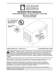
1
Updated – October 2013
4109 Capital Circle
Janesville, WI USA 53546
www.cleanburn.com
SPECIFICATIONS FOR CLEAN BURN WARM AIR FURNACE
MODEL CB-1750 CENTRAL FURNACE
PART 1 – GENERAL
1.1
DEFINITIONS: Throughout this bid specification the word “shall” appears frequently. The
word “shall” indicates a mandatory requirement as per the Codes and Regulations that
are listed in Part 1 – Section 1.4 through 1.4.4 of this bid specification as applicable.
1.2
REQUIREMENTS: General provisions of the purchase specifications, including general
and other conditions, delivery requirements, shipping and demurrage charges will be
under separate cover and shall apply.
1.3
SCOPE: This specification covers but is not limited to the furnishing of a CB-1750,
170,000 BTU/hr (input) Central Furnace Package. Thi s package will include the
following:
¾ One (1) CB-1750, 170,000 BTU/hr input central furnace (136,000 BTU/hr output)
¾ One (1) CB-525-S2 used-oil firing burner
¾ One (1) F-180 fan switch
¾ One (1) L-200 high limit switch
¾ One (1) L-290 auxiliary high limit switch (automatic reset)
¾ One (1) Lux Pro PSD Series 45 to 90 oF 24 vac wall mounted digital thermostat with
positive off position (non mercury)
¾ One (1) Suntec used oil pump assembly (Refer to Part 1 – Sectio n 2.5 for the listed
pump options)
¾ One (1) Oil pump relief valve assembly
¾ One (1) Lenz # DH750-100 canister filter with a washable 100-mesh stainless steel
screen filter element
¾ One (1) Oil vacuum gauge
¾ One (1) ¾” x ¾” in-line brass check valve
¾ One (1) ¾” in-line washable 50-mesh stainless steel screen filter eleme nt for the
check valve
¾ One (1) CB-1750 blower kit with a 3/4 h p motor @ 1,075rpm, semi enclosed, ODP,
PSC, sleeve bearing, cw-se rotation, 48YZ frame, direct drive (resilient) mounted,
5
5 /8” diameter fan motor, with a 10 uf (mfd) / 370 vac capacitor, delivering 1,700 cfm
of free air when used as a unit heater (no ductwork added). When adding ductwork
with the louvers fully ope ned and in stalled inside of the ductwork, you si ze the
ductwork fro 0.25” W.C. to deliver 1,550 cfm of d ucted air, or when you remove the
louvers and add ductwork, you size the ductwork for 0.40” W.C. to deliver 1,400 cfm
of ducted air
1
¾
¾
¾
¾
¾
One (1) Field Type ‘M’, 8” barometric damper
One (1) 8”, 24-gauge galvanized sheet metal cap
One (1) CB-1750 Operator’s Manual
Burner oil line and air line components
Miscellaneous bolts and fittings for assembly / installation of the appliance
Note: This is the standard package for the CB-17 50 Central Furnace. This
appliance can be in stalled as a unit heater without ductwork installed, or as a
central furnace with the properly sized ductwork installed. When ducting th e
appliance, you can duct all of the air from o ne side using the en tire 12” x 12”
opening or from two sides by reducing the two openings to 12” x 6” each. No
ductwork shall be placed on the bo ttom discharge opening. (Refer to the CB-1750
Operator’s Manual for the proper static pressure for the sizing of the ductwork).
1.4
CODES AND REGULATIONS: The installation of this ap pliance shall b e made i n
accordance with the ma nufacturer’s instructions, as well as i n accordance with all
Federal, State, Regional, or Local Laws and / or Regulations acceptable to the Authority
Having Jurisdiction (AHJ) and shall be accomplished only by a qualified, ce rtified, and
competent heating technician experienced in making such installations as per NFPA 31 –
Chapter 4 – Sections 4.3.2 and 4. 3.3 and the Codes and Regulations that are listed i n
Part 1 – Sections 1.4 through 1.4.4 of this bid specification as applicable.
1.4.1
The design, materials and workmanship of the app liance, burner unit, and th e various
other accessories furnished by Cle an Burn, LLC, as well as the in stallation of the
appliance, shall fully comp ly with the re quirements of UL Standard 296A (Und erwriter’s
Laboratories File # MH 15393 (N) and / or Underwriter’s Laboratories of Canada File #
CMP217) and NFPA 31 – Chapter 12 – Sections 12.1 through 12.4.3.
1.4.2
The installation shall fully comply with the following NFPA Codes: 30 – Flammable and
Combustible Liquids, 30A – Motor Fuel Dispensing Facilities and Repair Garages, 31 –
Standard for the Installation of Oil-Burning Equipment, 70 – National Electrical Code, 88A
– Standard for Parking Structures, 88B – Standa rd for Repair Garages, and 211 –
Standard for Chim neys, Fireplaces, Vents, and Solid-Fuel Burning Appliances as
applicable.
1.4.3
The installation shall fully comply with the following International Codes: International
Building Code, International Mechanical Code, International Fire Code , and the
International Fuel Gas Code as applicable.
1.4.4
The installation shall fully comply with the followin g CAN / CSA Standard s: (when
installing the appliance in Canada): B139-00 (ap proved October 2001) – Installation
Code for Oil-Burning Equipment, B140.0-M87 (reaffirmed 2001) – General Requirements
for Oil-Burning Equipment, and C22 .1-02 – Canadian Electric Code – P art 1 as
applicable.
1.5
RIGGING AND UNLOADING: Vendors shall deliver to the site all equipment,
components, and devi ces specified herein. Ri gging and / o r off-loading will be the
responsibility of the purchaser or the purchasers designated agent.
2
PART 2 – PRODUCT
2.1
FURNACE: The ap pliance shall be shipped factory assembled and pre-wired as a
single, packaged unit suitable for firing used-oils.
2.1.1
The appliance shall be UL / ULC listed and tested to burn the used-oils as per NFPA 31,
Chapter 12, Section 12.4.1, 12.4.2, and 12.4.3.
2.1.2
The appliance shall be complete with one used-oil burner assembly, one used-oil pump
assembly, and all devices and controls required for safe and efficient operation.
2.2
CONSTRUCTION: The appliance shall be of standard construction, having a three-pass
heat exchanger, with a hinged, swing out front door for easy access and cleaning.
2.2.1
The combustion chamber shall be made from 14-gauge steel and comes with a ceramic
fiberboard Energy Retention Disc. The remainder of the appliance cabinet and flue tubes
will be made form 16-gauge steel.
2.2.2
The appliance cabinet shall come with three air discharge openings. The air discharge
openings of the applia nce are 1 2” wide x 12” hi gh and will come with adjustable
directional louvers. These louvers shall be used wit h or without ductwork. (Refer to the
CB-1750 Operator’s Manual for the proper static pressure for the sizing of the ductwork.)
2.2.3
Two of the ai r discharges shall be located on eithe r side of the a ppliance, and one air
discharge shall be located at th e bottom of th e appliance. (Refer to th e CB-1750
Operator’s Manual for the proper placement of the louvers.)
2.2.4
A maximum of two air discharges may be used at the same time.
2.2.5
When using more than one air discharge, you must reduce the opening size to 12” wide x
6” high on both of the discharg es you are using. DO NOT USE the full 12” wide x 12”
high openings on the appl iance when you are u sing more than one discharge. You will
damage the blower motor.
2.2.6
When adding ductwork to the applia nce, you can only use the si de air discharge/louver
combination. DO NOT ADD any ductwork to the bottom air discharge. (Refer to the
CB-1750 Operator’s Manual for the proper use and application of ductwork.)
2.2.7
A 3” dia meter opening, with a spring closing flame observation port door shall be
provided at the front of the applian ce. This port shall be located on the left side of the
burner so that an inspection of the co mbustion chamber area can be made, both when
the appliance is in operation or at rest.
2.2.8
The front door shall be of a hinged, swing out design and shall be large enough to permit
access for the purpose of removing the ash and for the in spection of the combustion
chamber, Energy Retention disc, and flue tubes.
2.2.9
The front door panel shall be insulate d with an approved insulation material, a 2” thi ck
o
piece of 2,300 F ceramic fiberboard.
3
2.2.10
The appliance shall be provided with a wrap around 22-gauge, galvaneal steel jacket with
a baked on powder coat finish.
2.2.11
The size, capacity, and operation of t he appliance shall be designed as shown in the
following:
¾ 170,000 BTU/hr input rating
¾ 136,000 BTU/hr output rating
¾ 1.20 gph oil consumption
¾ Dedicated spst 20 amp electrical circuit rated @ 115vac / 60hz / 1 ph, requiring the
installation of a 12/2 copper power supply wire
¾ Dedicated spst 30 amp electrical circuit rated @ 115vac / 60hz / 1 ph (optional –
used when i nstalling a d raft inducer or on-board air compressor), requiring the
installation of a 10/2 copper power supply wire
¾ 2.0 cfm compressed air requirement @ 20 psig
¾ 8” stack size
¾ Cabinet dimensions (from burner end without the burner and the blower assembly
installed) 53” long x 29 ¼” wide x 29 ¼” high
¾ Overall dimensions (from burner end with both the burner and the blower assembly
installed) 83” long x 29 ¼” wide x 29 ¼” high
¾ Approximate shipping weight – 310 lbs
2.3
INSTALLATION: The ap pliance shall be ceiling hung, mounted on an approved stand,
or installed on a raised platform constructed on a non-combustible (concrete) floor, and
shall be installed as per the Codes and Regulations that are listed in Part 1 – Section 1.4
through 1.4.4 of this bid specification as applicable.
2.3.1
Appliances that are installed in repair garages shall be installed at least 8 feet above the
floor level a s per the Codes and Regulations that are listed in Part 1 – Se ction 1.4
through 1.4.4 of this bid specification as applicable.
2.3.2
The appliance is designed to be installed as either a unit heater without ductwork
installed, or as a central furnace with the properly sized ductwork installed. (Refer to the
CB-1750 Operator’s Manual for the proper static pressure for the sizing of the ductwork).
2.3.3
The appliance shall be supplied with the proper amount of combustion air to permit the
satisfactory combustion of the oil, the prop er venting of the com bustion gases, and to
maintain a safe ambient temperature within the space that the appliance is installed in as
per the Codes and Regulations that are listed in Part1 – Section 1.4 through 1.4.4 of this
bid specification as applicable.
2.3.4
When installing this appliance in a n unconfined space, the minimum amount of
combustion air supplied to this appliance shall be from one permanent opening, installed
within 12” of the ceiling of the room, totaling 39 square inches at a rate of 94 cfm of free
air for a single appliance application as per the Codes and Regulations that are listen in
Part 1 – Section 1.4 through 1.4.4 of this bid specification as applicable. When installing
more than one appliance into the same unconfined space, you must adjust these
minimum requirements to accept all of the appliances within that space.
4
2.3.5
When installing this appliance in a confined space, the minimum amount of combustion
air supplied to this appliance shall be from two permanent openings, one opening
installed within 12” of the ceiling of the room and one opening installed within 12” of the
floor of the room, with each opening totaling 49 square inches at a rate of 188 cfm of free
air for a single appliance application as per the Codes and Regulations that are listed in
Part 1 – Section 1.4 through 1.4.4 of this bid specification as applicable. When installing
more than one appliance into the same confined space, you must adjust these minimum
requirements to accept all the appliances within that space.
2.3.6
When installing louvers and grills to bring the combustion air into the room and the actual
free area of the louver or grill is not known, it is understood that wooden louvers and grills
will have a free area of 25% while metal louvers and grills will have a free area of 75% as
per the Codes and Regulations that are listed in Part 1 – section 1.4 through 1.4.4 of this
bid specification as applicable.
2.3.7
All louvers and grills, regardless of the material that they are made from, shall be fixed in
the open position, or be interlocked with the appliance(s) so that they will open
automatically during the operation of the applia nce(s). The interl ock must be placed on
the driven member as per the Codes and Regulations that are listed in Part 1 – Section
1.4 through 1.4.4 of this bid specification as applicable.
2.3.8
When installing a mechanical fan assembly to provide the combustion air, the fan shall be
interlocked with the a ppliance’s burner(s) so that combustion air is proven before and
during the operation of the appliance(s) as per the Codes and Regulations that are listed
in Part 1 – Section 1.4 through 1.4.4 of this bid specification as applicable.
2.3.9
The combustion air shall be supplied as per the Codes and Regulations that are listed in
Part 1 – Section 1.4 through 1.4.4 of this bid specification as applicable.
2.3.10
The appliance shall be installed to fit into the space available with the following minimum
clearances from combustible surfaces or for the servicing of the appliance:
¾ Top – 12”
¾ Front (burner) side – 60”
¾ Rear ( from blower) – 2”
¾ Bottom – 24”
¾ Side (without stack) – 18”
¾ Side (with air discharge) – 60”
¾ Stack – 18”
¾ Warm air ducts – 6”
2.3.11
Installation, operating, and maintenance permits may be required by the Authority Having
Jurisdiction (AHJ). It is the responsi bility of the purchaser, designa ted agent, contractor,
or installer of the appliance to check with the AHJ as to the pro per procedures to follow
for the completion of this installation.
2.3.12
Installation inspections of the finished job may also be required by the Authority Having
Jurisdiction (AHJ). It is the responsi bility of the purchaser, designa ted agent, contractor,
or installer of the appliance to check with the AHJ as to the pro per procedures to follow
for the completion of this installation.
5
2.3.13
On-site certification of the appliance may be required by the Authority Having Jurisdiction
(AHJ). It is the re sponsibility of the purch aser, designated agent, contractor, or installer
of the ap pliance to check with the AHJ a s to th e proper procedures to follow for the
completion of this installation.
2.3.14
It is the resp onsibility of the purch aser, designated agent, contractor, or in staller of the
appliance to check with the Authorit ies Having Jurisdiction (AHJ) as to the pro per
procedures to follow for the completion of this installation.
2.4
USED-OIL BURNER: Clean Burn, LLC. will supply one complete used-oil burner, factory
assembled, and suitable for the burning of used-oils.
2.4.1
The used-oil burner shall be UL / ULC listed and tested to burn the following used-oils:
¾ # 2, # 4, & # 5 fuel oils
¾ Used crankcase oils up to SAE 50 weight
¾ Used automatic transmission fluids
¾ Used hydraulic oils
2.4.2
The used-oil burner shall be constructed, wired, a nd fire te sted by Clean Burn, LLC. the
manufacturer.
2.4.3
The used-oil burner shall be shipped loose for field mounting and packaged in a separate
carton.
2.4.4
Clean Burn, LLC. shall manufacture the used-oil burner with quantity, capacity, and ratings
as per schedule.
2.4.5
The used-oil burner shall be equipped with a high resistance, flame retention, all stainless
steel firing head, with a conical stainless steel diffuser, and shall operate with no moving
parts. The flame pattern shall be such that impingement will not occur on the cham ber
walls at any load within the specified range of operating conditions.
2.4.6
The used-oil burner nozzle assembly shall contain the oil nozzle, the nozzle adapter, the
nozzle heater and thermostat, and the single piece electrode and shall be made in such a
way as to allow the nozzle assembly to be removable from the burner as a single unit.
2.4.7
The used-oil burner shall be equipped with both oil and air safety devices to prevent the
operation of the burner should either of these items fail durin g their norm al function.
These devices shall be controlled by the oil primary control and will stop the operation of
the burner upon flame or air failure.
2.4.8
The used-oil burner shall be controlled by a flame sensor device (a cadmium sulfide cell),
which will stop the burner when a flame failure occurs.
2.4.9
The flame sensor shall be connected to the primary safety control that shall fail in an
open position and “lock-out” the control.
2.4.10
The primary safety control shall require the manual resetting of the safety switch anytime
the burner has a no-oil or no-spark (ignition) condition.
6
2.4.11
If the primary safety control fails while in operation but the flam e has been established
and proven, the p rimary safety control shall be of a recycling type whi ch will allow the
burner up to three retries for ignition before the control will “lock-out”.
2.4.12
The primary safety control shall be co mpletely wired and tested b y the manufacturer for
this safety function.
2.4.13
Each used-oil burner shall be fully in accord with the requirements of and a pproved by
Underwriter’s Laboratories and Underwriter’s Laboratories of Canada.
2.4.14
The used-oil burner shall be factory fabricated and be complete with the following:
¾ One (1) Single burner / fan ho using assembly with side mounted combustion air
inlets
¾ One (1) Stainless steel flame retention head
¾ One (1) Hinged swing out mounting bracket
¾ One (1) 4-wire power cord disconnect assembly with connector plug and receptacle
th
¾ One (1) Burner motor with a 1/10 hp motor @ 3,000 rpm TENV, DP, PSC, sealed,
ball bearing, ccw-se rotation, N frame, stud mounted, 3.3” diameter motor, with a 7.5
uf (mfd) / 370 vac capacitor
¾ One (1) Integral squirrel cage draft fan
¾ One (1) Set of dual inner /outer combustion draft control plates
¾ One (1) Oil block assembly, heated
¾ One (1) 400 watt block heater, block mounted, thermostat controlled
¾ One (1) 120 oF block heater-proving switch, surface mounted
¾ One (1) 140 oF block thermostat, surface mounted
¾ One (1) Air regulator, surface mounted
¾ One (1) Oil solenoid, surface mounted
¾ One (1) Air solenoid, surface mounted
¾ One (1) Centrifugal proving switch, internally motor mounted
¾ One (1) Air pressure proving switch, block mounted
¾ One (1) Carlin # 41000B, 14,000 vac electric igniter
¾ One (1) Carlin # 42230-02, 30 second safety timing, solid-state primary control with
manual reset safety switch
¾ One (1) Honeywell # C-554A cadmium sulfide flame sensor
¾ One (1) Single piece direct spark igniter
¾ One (1) heated nozzle adapter, thermostat controlled.
¾ One (1) L-130 thermostat, nozzle adapter mounted
¾ One (1) 140 watt nozzle heater, nozzle adapter mounted, thermostat controlled
¾ One (1) Delavan 9-5 nozzle
¾ One (1) 0-15 psig oil pressure gauge, burner mounted
¾ One (1) 0-60 psig air pressure gauge, burner mounted\
¾ One (1) Run time hour meter, burner mounted
¾ One (1) Green indicator light for power on indication, burner mounted
¾ One (1) Amber indicator light for oil pump on indication, burner mounted
7
2.5
USED-OIL FUEL SYSTEM: The CB-1750 Central Furnace is available with two choices
of oil pumps that are both rated for use with used-oil applications. The pumps will have
the following description:
Option #1 – Metering Pump Assembly
¾ One (1) Suntec model A2RA-7710 used-oil pump assembly with a 1/20th hp motor @
196 rpm, TENV, DP, PS C, sealed, ball bearing, ccw-se rotation, 10 0 AC frame,
parallel shaft, close coupled stud m ounted, 3.42” diameter gear motor, with a 6 uf
(mfd) /250 vac capacitor
¾ One (1) Oil pump relief valve assembly
¾ One (1) Lenz # DH750-100 canister filter with a washable 100-mesh stainless steel
screen filter element
¾ One (1) Oil vacuum gauge
¾ One (1) ¾” x ¾” in-line brass check valve
¾ One (1) ¾” in-line washable 50-mesh stainless steel screen filter element for the
check valve.
Option # 2 – Pressure Style Pump Assembly
th
¾ One (1) Suntec model J4NB-A1000G used-oil pump assembly with a 1/6 hp motor
@ 1,725 rpm, TENV, DP, ball b earing, ccw-se rotation, 48 N frame, parallel shaft,
close coupled, 7 ¼” bolt hole mount (center to center), 5 ½” diameter motor
¾ One (1) Lenz # DH750-100 canister filter with a washable 100-mesh stainless steel
screen filter element
¾ One (1) ) Oil vacuum gauge
¾ One (1) ¾” x ¾” in-line brass check valve
¾ One (1) ¾” in-line washable 50-mesh stainless steel screen filter element for the
check valve
¾ One (1) Oil regulator, surface mounted (used only on burners that use a ‘J’ pump)
2.5.1
The Suntec model A2RA-7710 used-oil pump assembly (option # 1) sh all be installed as
a suction fed only pump and it shall h ave a maxi mum vertical lift capa city of 6 feet of
suction oil line plus a maximum of 4 feet of horizontal suction line.
2.5.2
The Suntec model A2RA-7710 used-oil pump assembly (option # 1) is not an adjustable
pressure range pump. The gear motor is rated to deliver the correct amount of fuel per
hour (1.20 gph) to the burner unit.
2.5.3
The Suntec model A2RA-7710 used-oil pump a ssembly (option # 1) shall have a
washable 234-micron stainless steel fi lter screen installed inside of the pump head.
(Refer to the CB-1750 Operator’s Manual for the proper installation of this pump.)
2.5.4
The suction oil line size for the Suntec model A2RA-7710 used-oil pump (option # 1) shall
be ½” OD copper tubing for the suction line from the used-oil tank to the pump.
2.5.5
The pressure oil line size for the Suntec model A2RA-7710 used-oil pump (o ption # 1)
shall be 3/8” OD co pper tubing fro m the used-oil pump head to t he burner unit with a
maximum run of 10 0 feet of tubing. (Please note that som e installations will allow for a
greater pressure line length. Contact your Auth orized Clean Burn Distributor for more
information.)
2.5.6
The Suntec model J4NB-A1000G used-oil pump assembly (option # 2) shall be installed
as a suction fed only pump and it shall have a maximum vertical lift capacity of 10 feet of
suction oil line plus a maximum of 30 feet of horizontal suction oil line (not to exceed 10”
Hg of vacuum).
8
2.5.7
The Suntec model J4NB-A1000G use-oil pump (option # 2 ) shall have a n adjustable
pressure range of 20 to 40 psig.
2.5.8
The Suntec model J4NB-A1000G use-oil pump (option # 2) shall have a washable
234-micron stainless steel filter screen installed inside of the pump head. (Refer to the
CB-1750 Operator’s Manual and the J-Pump Inst aller’s Manual for the proper installation
of this pump.)
2.5.9
The suction oil line size for the Sunte c model J4NB-A1000G use-oil pum p (option # 2)
shall be ½” OD copper tubing running from the used-oil tank to the pump head.
2.5.10
The pressure oil line size, from the used-oil pump head to the burner unit, for the Suntec
model J4NB-A1000G use-oil pump (option # 2) shall be 3/8 ” OD copper tubing if less
than 75’ and ½” OD copper tubing if it is 75’ to a maximum of 150’.
2.5.11
All of the Clean Burn u sed-oil fuel supply units a re designed to be u sed as one-pipe
suction fed pump system.
2.5.12
It is re commended that t he used-oil be supplied from an inside tank for the best
performance and operation of the appliance.
2.5.13
It is recomm ended that when u sing an outside ab ove ground tank or a n outside below
ground tank that you in stall a “day tan k” inside of th e building and a pum ping transfer
system for the best performance and operation of the appliance.
2.5.14
The used-oil pump assembly shall be mounted above the oil tank and be as close to the
top of the tank as possible.
2.5.15
When installing more than one appliance into the building each appliance shall have its
own used-oil pump assembly for each burner.
2.5.16
A return line from the pump to the tank is not required. However, with the metering pump
assembly (option # 1) there is a relief valve assembly on the outlet of the pump head tha t
requires a return line to the tank.
2.5.13
The used-oil pump assembly shall be a close coupled gear type pump.
2.6
STACK: Th e CB-1750 Central Fu rnace requires one 8” sta ck off of either sid e of the
appliance. The un-used stack bre eching must be capp ed off with the 8”, 24-ga uge
galvanized sheet metal cap that is included with the appliance.
2.6.1
The appliance includes one Field Type ‘M’ 8” barometric damper. This dam per shall be
installed in the exhaust stack leaving the appliance and be installed within 3 to 5 feet of
the breeching outlet as per the Codes and Regulations that are listed in Part 1 – Sections
1.4 through 1.4.4 of this bid specification as applicable.
2.6.2
This barometric damper shall be adjusted to maintain a natural draft over-the-fire of -.02”
W.C. to a -.04” W.C. and a stack draft of -.04” W.C. to -.06” W.C. at all times.
2.6.3
All other stack materials needed to install this appliance shall be the responsibility of the
installer.
2.6.4
Single wall stack can be used on the appliance on the inside of the building only. Where
single wall stack can be used it must be 24-gauge galvanized sheet metal only as per the
Codes and Regulations that are li sted in Part 1 – Section 1.4 through 1.4.4 of this bi d
specification as applicable.
9
2.6.5
DO NOT US E Type ‘B’ or ‘BW’ Vent which is a non-insulated double walled stack
approved for LP and natural gas fired a ppliances only as per the Codes and Regulations
that are listed in Part 1 – Sections 1.4 through 1.4.4 of this bid specification as applicable.
2.6.6
DO NOT USE Type ‘L’ Vent whi ch is a non-insulated double walled stack approved for
some #2 fuel oil an d pellet burning appliances only as per the Codes and Regulations
that are listed in Part 1 – Sections 1.4 through 1.4.4 of this bid specification as applicable.
2.6.7
DO NOT USE the black decorative style of vent whi ch is a single walled stack approved
for solid-fuel burning appliances only as per the Codes and Regulations that are listed in
Part 1 – Sections 1.4 through 1.4.4 of this bid specification as applicable.
2.6.8
Where any penetration of a floor, a wall, through the ceiling, into an attic space, where
people may brush against the outside surface of the stack, or when you run any stack on
the exterior of the building, you shall use an all-fuel pipe material that meets UL Standard
103 Type HT pipe requirements as per the Codes and Regulations that are listed in Part
1 – Sections 1.4 through 1.4.4 of this bid specification as applicable.
2.6.9
Stack that i s installed and used for th is penetration protection of the buildin g, shall be
o
rated for a chimney temperature suitable for use at 1,000 F, and shall b e tested to the
UL Standard 103 Type HT pipe requirement as per the Codes and Regulations that are
listed in Part 1 – Sections 1.4 through 1.4.4 of this bid specification as applicable.
2.6.10
The all-fuel /UL 103 Type HT double walled insulated stack with stainless steel inner core
is available through the local Clean Burn Distributor. (Refer to the CB-1750 Operator’s
Manual for th e proper way to install the st ack, and whe n to use single wall st ack and
when you must use the all-fuel /UL 103 Type HT double walled insulated stack.)
10
PART 3 – ADDITIONAL INFORMATION
3.1
GENERAL: The in stallation of this appliance shall be mad e in accordance with the
manufacturers’ instructions, as well as in accordance with all Federal, State, Regional, or
Local Laws and / o r Regulations acceptable to th e Authority Having Jurisdiction (AHJ)
and shall b e accomplished only by a qualifi ed, certified, a nd competent heating
technician experienced in making such installations as per NFPA 31, Chapter 4, Sections
4.3.2 and 4.3 .3 and the Code s and Re gulations that are listed in Part 1 – Sections 1.4
through 1.4.4 of this bid specification as applicable.
3.1.1
Installation, operation, and maintenance permits may be required by the Authority Having
Jurisdiction (AHJ). It is the responsi bility of the purchaser, designa ted agent, contractor,
or installer of the appliance to check with the AHJ as to the pro per procedures to follow
for the completion of this installation.
3.1.2
Installation inspections of the finished job may also be required by the Authority Having
Jurisdiction (AHJ). It is the responsi bility of the purchaser, designa ted agent, contractor,
or installer of the appliance to check with the AHJ as to the pro per procedures to follow
for the completion of this installation.
3.1.3
On-site certification of the appliance may be required by the Authority Having Jurisdiction
(AHJ). It is the re sponsibility of the purch aser, designated agent, contractor, or installer
of the ap pliance to check with the AHJ a s to th e proper procedures to follow for the
completion of this installation.
3.1.4
All appliances shall be tested and installed in accordance with the Codes and
Regulations that are liste d in Part 1 – Section s 1.4 through 1.4.4 of this bid spe cification
as applicable.
3.1.5
All materials utilized in the installation shall be in strict accordance with the Codes and
Regulations that are liste d in Part 1 – Section s 1.4 through 1.4.4 of this bid spe cification
as applicable and shall be new and of the best grade and quality.
3.1.6
The bidder must have local service capability to provide on-site service.
3.1.7
The bidder must have current autho rization from Clean Burn, LLC. to provid e warranty
service.
3.2
OPERATOR MANUALS: Each appliance comes with one complete CB-1750 Operator’s
Manual included inside of the appliance at time of shipping. Clean Burn, LLC. will supply
up to four additional CB-1750 Operator’s Manuals at no charge for the bidding purpose.
If more copies of CB-1750 Operator’s Manuals are required, they can be ordered through
the local Clean Burn Distributor.
11
PART 4 – WARRANTY
4.1
WARRANTY INFORMATIOIN: Cl ean Burn, LLC. shall warrant the CB-17 50 Central
Furnace and all oth er Clean Burn products to be free from defects in material and
workmanship under normal use according to the provisions and limitations set in the CB1750 Operator’s Manual for a period of one year from the date of purchase by the original
purchaser.
4.1.1
Clean Burn warrants the heat exchanger/combustion chamber for a period of ten (10)
years (or 15,000 hours, whichever comes first), from the date of purchase by the
purchaser, as follows:
If the defect occurs in the first five (5) years (or 7500 hours, whichever comes first) Clean
Burn pays 100% of parts, replacement or repair (the customer pays 0%), and pro rata
thereafter according to the following schedule:
(a) If the defect occurs during the sixth year (or 7500-9000 hours, whichever
comes first), customer pays 70% of parts, replacement or repair.
(b) If the defect occurs during the seventh year (or 9000-10,500 hours, whichever
comes first), customer pays 75% of parts, replacement or repair.
(c) If the defect occurs during the eighth year (or 10,500-12,000 hours, whichever
comes first), customer pays 80% of parts, replacement or repair.
(d) If the defect occurs during the ninth year (or 12,000-13,500 hours, whichever
comes first), customer pays 85% of parts, replacement or repair.
(e) If the defect occurs during the tenth year (or 13,500-15,000 hours, whichever
comes first), customer pays 90% of parts, replacement or repair.
Clean Burn warrants all other component parts, including the energy retention disk,
for a period of one (1) year from the date of purchase by the purchaser.
4.1.2
The customer shall be responsible for all freight charges incurred for any replacement
parts of ap pliance cabinets shipped to either the Clean Burn Distributor or to th e
customer during the covered warranty period.
4.1.3
A complete warranty covering this ap pliance can be found inside the front cover of th e
CB-1750 Operator’s Manual.
4.1.4
Clean Burn, LLC. does not warrant any labor for the installation o f any failed parts, the
labor for the removal and re-installation of the a ppliance cabinet for any repairs done to
the appliance or for the total replacement of the cabinet, or any labor for repairs done to
the appliance during the warranty period.
4.1.5
Clean Burn, LLC. is n ot responsible for any freight or expenses that may be re quired to
ship any repair parts or replacement cabinets to either the Clean Burn Distributor or to
the customer.
4.1.6
No other warranty, verbal, implied, or written shall be honored by Clean Burn, LLC. unless
it comes directly from Clean Burn’s Director of Field Engineering & Technical Support in
written form with all parties notified as to the changes and / or additions in the warranty.
12