1
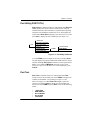
E&M+ Dual Voice Option Module
Part Number
1200105L3
E&M+ Dual Voice Plug-On Board
Part Number
1200106L3
User Manual
December 2003
61200105L3-1A
Trademarks:
Windows is a registered trademark of Microsoft Corp.
T-Watch PRO is a trademark of ADTRAN, Inc.
OpenViewR
901 Explorer Boulevard
P.O. Box 140000
Huntsville, AL 35814-4000
Phone: (256) 963-8000
© 2003 ADTRAN, Inc.
All rights reserved.
Printed in USA.
The following conventions are used in this manual.
Notes provide additional useful information.
Cautions signify information that could prevent service interruption.
Warnings provide information that could prevent damage to the
equipment or endangerment to human life.
Important Safety Instructions
When using your telephone equipment, please follow these basic safety precautions to
reduce the risk of fire, electrical shock, or personal injury:
1.
2.
3.
4.
5.
Do not use this product near water, such as near a bathtub, wash bowl, kitchen sink,
laundry tub, in a wet basement, or near a swimming pool.
Avoid using a telephone (other than a cordless-type) during an electrical storm.
There is a remote risk of shock from lightning.
Do not use the telephone to report a gas leak in the vicinity of the leak.
Use only the power cord, power supply, and/or batteries indicated in the manual.
Do not dispose of batteries in a fire. They may explode. Check with local codes for
special disposal instructions.
Save These Important Safety Instructions
iii
Federal Communications Commission
Radio Frequency Interference Statement
This equipment has been tested and found to comply with the limits for a Class A digital
device, pursuant to Part 15 of the FCC Rules. These limits are designed to provide reasonable protection against harmful interference when the equipment is operated in a commercial environment. This equipment generates, uses, and can radiate radio frequency energy
and, if not installed and used in accordance with the instruction manual, may cause harmful interference to radio frequencies. Operation of this equipment in a residential area is
likely to cause harmful interference in which case the user will be required to correct the
interference at his own expense.
Shielded cables must be used with this unit to ensure compliance with Class A
FCC limits.
Change or modifications to this unit not expressly approved by the
party responsible for compliance could void the user’s authority to
operate the equipment.
iv
Product Warranty
ADTRAN will repair and return this product within the warranty period if it
does not meet its published specifications or fails while in service. Warranty
information can be found at www.adtran.com.
Product Registration
Registering your product helps ensure complete customer satisfaction. Please
take time to register your products on line at www.adtran.com. Click Service
and Support on the top of the page, and then click Product Registration under
Support.
Customer Service, Product Support Information, and Training
ADTRAN will repair and return this product within five years from the date of shipment
if the product does not meet its published specification, or if it fails while in service.
A return material authorization (RMA) is required prior to returning equipment to
ADTRAN. For service, RMA requests, training, or more information, see the toll-free
contact numbers given below.
Presales Inquiries and Applications Support
Please contact your local distributor, ADTRAN Applications Engineering, or ADTRAN
Sales:
Applications Engineering
(800) 615-1176
Sales
(800) 827-0807
Post-Sale Support
Please contact your local distributor first. If your local distributor cannot help, please contact ADTRAN Technical Support and have the unit serial number available.
Technical Support
(888) 4ADTRAN
The Custom Extended Services (ACES) program offers multiple types and levels of service plans which allow you to choose the kind of assistance you need. For questions, call
the ACES Help Desk.
ACES Help Desk
(888) 874-2237
v
Repair and Return
If ADTRAN Technical Support determines that a repair is needed, Technical Support will
coordinate with the Custom and Product Service (CaPS) department to issue an RMA number. For information regarding equipment currently in house or possible fees associated
with repair, contact CaPS directly at the following number:
CaPS Department
(256) 963-8722
Identify the RMA number clearly on the package (below address), and return to the following address:
ADTRAN Customer and Product Service
901 Explorer Blvd.
Huntsville, Alabama 35806
RMA # _____________
Training
The Enterprise Network (EN) Technical Training offers training on our most popular products. These courses include overviews on product features and functions while covering applications of ADTRAN's product lines. ADTRAN provides a variety of training options,
including customized training and courses taught at our facilities or at your site. For more information about training, please contact your Territory Manager or the Enterprise Training
Coordinator.
vi
Training - phone
(800) 615-1176, ext. 7500
Training - fax
(256) 963-6700
Training - email
[email protected]
Table of Contents
List of Figures ............................................................................................................ix
List of Tables ..............................................................................................................xi
Chapter 1. Introduction ............................................................................................ 1-1
E&M+ Dual Voice Overview ..................................................................................... 1-1
Functional Description .......................................................................................... 1-2
Features ......................................................................................................... 1-2
E&M+ Option Module Specifications .......................................................... 1-3
Physical Description ............................................................................................. 1-4
Chapter 2. Installation .............................................................................................. 2-1
Unpack and inspect ..................................................................................................... 2-1
Shipped by ADTRAN ........................................................................................... 2-1
Provided by Customer........................................................................................... 2-1
Installing the option module ........................................................................................ 2-2
Modules With Hot Replaceable Label on Back Panel .......................................... 2-2
Modules Without Hot Replaceable Label on Back Panel..................................... 2-2
Placement of the Option Module .......................................................................... 2-3
Power Connection ......................................................................................... 2-3
Attaching the Plug-On Board ....................................................................... 2-4
Rear Panel Connectors .......................................................................................... 2-5
Wiring ........................................................................................................... 2-6
Power up testing and initialization .............................................................................. 2-7
Successful Self-Test .............................................................................................. 2-7
Failed Self-Test ..................................................................................................... 2-7
Operation Alarms .................................................................................................. 2-7
Chapter 3. Operation ................................................................................................ 3-1
Menu Structure ............................................................................................................ 3-1
Menu Operation ........................................................................................................... 3-1
E&M+ Menu Items ..................................................................................................... 3-2
Port Status ............................................................................................................. 3-3
61200105L3-1A
E&M+ Dual Voice Option Module User Manual
vii
Table of Contents
E&M Status ................................................................................................... 3-3
View Signaling Bits (VIEW SIG BITS) .......................................................3-4
Port Configuration (Port Config) .......................................................................... 3-4
Mode ............................................................................................................. 3-5
Receive Level/Transmission Level Point (RX LVL (TLP)) ......................... 3-6
Transmit Level/Transmission Level Point (TX LVL (TLP)) ....................... 3-6
Fault Response (FAULT RESP) ................................................................... 3-6
2713 Hz Tone Detection (2713 TONE DET) ............................................... 3-6
Port Utility (PORT UTIL)..................................................................................... 3-7
Port Test ................................................................................................................ 3-7
1 kHz Tone .................................................................................................... 3-8
View Signaling Bits ......................................................................................3-8
Set Transmit Signal ....................................................................................... 3-9
Set E-Lead ..................................................................................................... 3-9
Loopback .......................................................................................................3-9
TSU Features Used with E&M+ Options .................................................................. 3-10
Factory Restore ................................................................................................... 3-10
Run Self Test....................................................................................................... 3-10
Appendix A. E&M+ Menu Tree ............................................................................ A-1
Appendix B. E&M+ Failure Messages .................................................................. B-1
Appendix C. Signaling States ................................................................................. C-1
Index ...................................................................................................................Index-1
viii
E&M+ Dual Voice Option Module User Manual
61200105L3-1A
List of Figures
Figure 1-1. E&M+ Dual Voice Option Module ..........................................................1-4
Figure 1-2. E&M Dual Voice Plug-on Board ..............................................................1-4
Figure 2-1. Installing the Option Module ....................................................................2-3
Figure 2-2. Attaching the Plug-on Board.....................................................................2-4
Figure 2-3. E&M+ Option Module Rear View............................................................2-5
Figure 3-1. TSU 100 Main Menu ................................................................................3-2
Figure 3-2. Port Status Submenus................................................................................3-3
Figure 3-3. E&M Status Display .................................................................................3-3
Figure 3-4. View Signaling Bits Display .....................................................................3-4
Figure 3-5. Port Configuration Submenus ...................................................................3-5
Figure 3-6. Port Utility Submenus ...............................................................................3-7
Figure 3-7. Port Test Submenus...................................................................................3-8
Figure 3-8. View Signaling Bits Display .....................................................................3-9
Figure A-1. E&M+ Menu Tree ...................................................................................A-2
61200105L3-1A
E&M+ Dual Voice Option Module
ix
List of Figures
x
E&M+ Dual Voice Option Module
61200105L3-1A
List of Tables
Table 2-1. E&M Voice Pinout Connection ................................................................ 2-6
Table 3-1. Port Configuration Menu Items................................................................. 3-5
Table 3-2. Port Test Parameters.................................................................................. 3-8
Table C-1. E&M+ Signaling States ............................................................................C-1
61200105L3-1A
E&M+ Dual Voice Option Module
xi
List of Tables
xii
E&M+ Dual Voice Option Module
61200105L3-1A
Introduction
Chapter 1
E&M+ DUAL VOICE OVERVIEW
The E&M+ Dual Voice option module (“the E&M+ voice module”)
is one of the option modules available for ADTRAN’s TSU
100/120/600 (“the TSU”). The E&M+ voice module (P/N
1200105L3) provides two voice-grade interfaces, either 2-wire
(2W) or 4-wire (4W). These interfaces serve as tie-trunks using
E&M signaling or as dedicated transmission only (TO) interfaces
for additional data services.
The E&M+ voice module accepts the E&M+ plug-on board as well
as other plug-on modules. The E&M+ plug-on board provides up to
four functional ports per option slot. (In addition, the E&M+ plugon board may be plugged onto any existing TSU option module.)
The E&M+ voice module and E&M+ plug-on board are compatible
with the following E&M interface types: Type I, Type II, and Type
V (same premises wiring). The E-lead originates on these interface
types, while the M-lead originates on interfaces typically found on
PBXs and switching equipment.
Select the E&M signaling type using the jumper located near the
rear panel of the TSU. Placing the jumper across Pins 1 and 2,
enables Type I and Type II E&M signaling. Placing the jumper
across Pins 2 and 3, enables Type V E&M signaling. (Appendix C,
Signaling States, on page C-1 provides additional information.)
61200105L3-1A
•
The J1 JUMPER is located on the E&M+ plug-on board
(P/N 1200106L3) directly to the right of the ADTRAN logo.
•
The J2 JUMPER is located on the E&M+ voice module
board, (P/N 1200105L3) near the rear panel directly to the
right of the ADTRAN logo.
E&M+ Dual Voice Option Module User Manual
1-1
Chapter 1. Introduction
Functional Description
The E&M+ voice module fits into the TSU’s option slot, and, once
installed, the TSU governs the E&M+ voice module’s operation
and control. To configure the E&M+ voice module, use the TSU
front panel, or use ADTRAN’s personal computer (PC) management program, T-Watch PRO. (The internal E&M+ voice module
menus are automatically installed when it is plugged into the TSU.)
Features
Features of the E&M+ voice module include the following:
•
64 kbps voice port operation
•
Menu configurable Tx and Rx levels (TLPs)
•
2W and 4W E&M signaling as well as 2W and 4W TO
operation
•
E-lead originate E&M interface
•
Type I, II, and V signaling
•
Extensive testing capabilities:
- Rx and Tx signal bit monitoring
- E-lead and M-lead status monitoring
- Integral 1 kHz tone generation sends test tone towards near
or far end
- Manual control of Tx A and B signal bits
- Manual control of E-lead output
- Bidirectional analog loopback
- Loopback control by means of 2713 Hz tone from network
side
1-2
•
E&M+ plug-on board provides the TSU with four voice ports
in one option slot
•
Selectable E-lead force busy for carrier failure
•
Full V.34 modem capable (28.8 kbps)
E&M+ Dual Voice Option Module User Manual
61200105L3-1A
Chapter 1. Introduction
E&M+ Option Module Specifications
The E&M+ voice module conforms to the following specifications:
Voice Channels
Two (four with plug-on module installed)
Transmission Levels
TX:
+13 to -17 dB TLP
1 dB steps between -17 db and +6 dB
7 dB step between +6 dB and +13 dB
RX: -17 to +7 dB TLP, 1 dB steps
Frequency Response
300 to 3400 Hz (+1.0 dB)
4-wire Impedance
600 Ω
2-wire Impedance
600 Ω + 2.15 µF
2-wire ERL
>20 dB
2-wire SRL
>15 dB
THL ERL
>25 dB
THL SRL
>20 dB
Longitudinal Bal
>52 dB
RX Idle Channel Noise <20 dBrnc
TX Idle Channel Noise <20 dBrnc
Operating Temperature 0-50°C, 95% relative humidity, noncondensing
Connector
RJ-45
Tests
• Power-on circuit test
• Signal bits monitoring and setting
• 1-kHz test tone generation
• Settable E-lead port output state
• Analog bidirectional loopback, controlled
from front panel (all versions). Also, by
2713-Hz control tone from the network side
(L3 versions only). Control tone operation is
similar to AT&T PUB 43004, with tone level
-24 dBm to -3 dBm. (This feature operates in
TO mode only.)
61200105L3-1A
E&M+ Dual Voice Option Module User Manual
1-3
Chapter 1. Introduction
Physical Description
The E&M+ voice module plugs into the option slot in the rear of
the TSU (see Figure 1-1). A removable plastic plug covers the
E&M+ voice module rear panel cutout that can house additional
connectors, such as the E&M+ plug-on board (see Figure 1-2).
Figure 1-1. E&M+ Dual Voice Option Module
Figure 1-2. E&M Dual Voice Plug-on Board
1-4
E&M+ Dual Voice Option Module User Manual
61200105L3-1A
Chapter 1. Introduction
The E&M+ plug-on board labels PORT X.3 and PORT X.4 correlate
to the port numbering philosophy of the TSU 100/120/600 family
where X represents the slot number, and .3 and .4 indicate the port
numbers. In this application, the port designations for the two
E&M+ voice module ports are 1.1 and 1.2. and, if added, the plugon board port designations are 1.3 and 1.4. These port numbers
appear in the front panel LCD menu displays.
61200105L3-1A
E&M+ Dual Voice Option Module User Manual
1-5
Chapter 1. Introduction
1-6
E&M+ Dual Voice Option Module User Manual
61200105L3-1A
Installation
Chapter 2
UNPACK AND INSPECT
Carefully unpack and inspect the E&M+ voice module or E&M+
plug-on board for any shipping damage. If damage is suspected, file
a claim immediately with the carrier and then contact ADTRAN
Technical Support. If possible, keep the original shipping container
for use in returning the equipment for repair or for verification of
damage during shipment.
Shipped by ADTRAN
The following items are included in the ADTRAN shipment:
•
E&M+ Dual Voice option module (P/N 1200105L3)
•
E&M+ Dual Voice plug-on board (P/N 1200106L3)
•
User Manual, to be inserted into main TSU 100/120/600 user
manual. (P/N 61200105L3-1A)
Provided by Customer
The customer must provide a cable for connection to the station.
61200105L3-1A
E&M+ Dual Voice Option ModuleUser Manual
2-1
Chapter 2. Installation
INSTALLING THE OPTION MODULE
Before installing the option module, check the back panel for the
presence or absence of a Hot Replaceable label on the back panel.
Modules With Hot Replaceable Label on Back Panel
Power to the TSU 100/120/600 may be ON when installing or
removing the option module with a Hot Replaceable label on the
back panel.
Modules Without Hot Replaceable Label on Back
Panel
Power to the TSU 100/120/600 must be OFF when installing or
removing the option module without a Hot Replaceable label on the
back panel.
2-2
E&M+ Dual Voice Option ModuleUser Manual
61200105L3-1A
Chapter 2. Installation
Placement of the Option Module
The following steps and Figure 2-1 describe the proper placement
of the E&M+ voice module.
1.
Remove cover plate from the TSU 100/120/600 rear panel.
2.
Slide the E&M+ voice module into the rear panel until it is
positioned firmly against the front of the TSU 100/120/600.
3.
Fasten the thumbscrews at both edges of the E&M+ voice
module.
Cover Plate
TSU
UNIT
Option Module
DUAL E&M
PORT X.1
PORT
X.2
PORT X.3/X.4
Figure 2-1. Installing the Option Module
Power Connection
Each E&M+ voice module derives power from the TSU 100/120/
600 unit. (Power to the TSU 100/120/600 is supplied by a captive
eight-foot power cord.)
61200105L3-1A
E&M+ Dual Voice Option ModuleUser Manual
2-3
Chapter 2. Installation
Attaching the Plug-On Board
The following steps and Figure 2-2 describe the proper attachment
of the E&M+ plug-on board to any option module.
1.
Hold the E&M+ plug-on board above the option module.
2.
Using a downward and right-to-left motion, slip the E&M+
plug-on board connector into the opening in the option module
back panel.
3.
Moving the E&M+ plug-on board downward, secure the connection of the header pins at the front of the boards.
4.
Install two 4-40 screws at both front edges of the option module.
5.
Install two 4-40 screws on each of the stand-offs on the rear of
the plug-on module.
Figure 2-2. Attaching the Plug-on Board
Visually verify the proper connection of the header pins between
the E&M+ voice module and the E&M+ plug-on board. An improper connection can result in severe damage to the equipment.
2-4
E&M+ Dual Voice Option ModuleUser Manual
61200105L3-1A
Chapter 2. Installation
The E&M+ plug-on board may be plugged onto any existing TSU
option module, including the E&M+ voice module.
Rear Panel Connectors
The rear panel contains two high-density subminiature DTE
connectors which provide V.35 or EIA-232 interfaces via custom
cables. Pin assignments for the DTE connections are listed in
Table 2-1 on page 2-6. Figure 2-3 show the E&M+ voice module
rear panel.
Figure 2-3. E&M+ Option Module Rear View
61200105L3-1A
E&M+ Dual Voice Option ModuleUser Manual
2-5
Chapter 2. Installation
Wiring
The E&M+ voice module provides two analog voice interfaces.
These universal connectors accept an RJ-45 (8-pin) connector. The
required wiring connection is an 8-Pin Modular Jack, Mating
Connector (P/N AMP # 2-383021-5). Table 2-1 shows the
E&M+ voice module pinout connection.
Table 2-1. E&M Voice Pinout Connection
Pin
2-6
Name
Description
1
Ring
Customer TX Ring; also 2W Ring
2
Tip
Customer TX Tip; also 2W Tip
3
E-lead
Customer originate E-lead
4
SG
E-lead ground return
5
SB
M-lead battery source
6
M-lead
Network originate M-lead
7
Tip 1
Customer RX Tip 1 (4W only)
8
Ring 1
Customer RX Ring (4W only)
E&M+ Dual Voice Option ModuleUser Manual
61200105L3-1A
Chapter 2. Installation
POWER UP TESTING AND INITIALIZATION
The E&M+ voice module executes a partial self-test during the
power up sequence, as described in the TSU 100/120/600 manual.
A full self-test can be activated from the TEST menu. No
initialization input is required. Any previously configured setting
for the option module is restored automatically upon power up.
Successful Self-Test
The green OK LED, located with the module LEDs on the TSU
front panel, turns ON when a successful self-test is completed and
the configuration is successfully restored. See Front Panel
Operation in the TSU 100/120/600 user manual.
Failed Self-Test
If the E&M+ voice module fails one or more of the self-tests, the
LCD displays a failure message during power up. Appendix B,
E&M+ Failure Messages on page B-1, describes specific failures
of the E&M+ voice module. (Also see the TSU 100/120/600 user
manual.)
Operation Alarms
When an alarm condition exists, the Red Alarm LED, located with
the module LEDs on the TSU front panel, turns ON.
61200105L3-1A
E&M+ Dual Voice Option ModuleUser Manual
2-7
Chapter 2. Installation
2-8
E&M+ Dual Voice Option ModuleUser Manual
61200105L3-1A
Chapter 3
Operation
The TSU 100/120/600 controls the E&M+ voice module. See the
TSU 100/120/600 User Manual for descriptions of the TSU front
panel indicators and buttons, and for additional operation
information.
MENU STRUCTURE
When an E&M+ voice module is installed in the TSU 100/120/600,
the TSU adds the module to its list of available options under
PORT MENU. These menu items are shown in bold in the
abbreviated TSU 100 menu shown in Figure 3-1 on page 3-2. See
Figure A-1 on page A-2 for the complete E&M+ voice module
menu tree. See the TSU 100/120/600 User Manual for a complete
menu diagram.
MENU OPERATION
Before any option module menus are applicable, an option module
must be selected from the listing in one of the PORT MENU options.
To select an option module, place the cursor on one of the PORT
MENU items, and press Enter. The resulting list displays all of the
currently installed option modules. To activate menus for the
E&M+ voice module, scroll through the list to display X.1 E&M+
and press Enter.
Once the E&M+ voice module is selected, the E&M+ menus
appear as a subset of, and operate the same as, menus for the TSU
100/120/600. With the cursor on one of the TSU 100/120/600 four
main menu choices, press Enter or a menu number to display the
first two submenu items.
61200105L3-1A
E&M+ Dual Voice Option ModuleUser Manual
3-1
Chapter 3. Operation
Use the up and down arrows to place the cursor on the appropriate
item and press Enter to display its first two submenu choices.
1) NI PERF RPTS
1) STATUS
2) NI ERRORS
3) ACTIVE ALARMS
2) CONFIG
1) NETWORK (NI)
4) VIEW HISTORY
2) UNIT
5) PORT STATUS
3) MAP XCHNG
6) REMOTE PORT
4) MAP IN USE (A) (B)
7) CLEAR PORT ALM
5) DS0 MAP A
8) ENET STATUS
6) DS0 MAP B
TSU 100
7) PORT CONFIG
Main Menu
1) TIME/DATE
3) UTIL
2) FACT RESTORE
3) SET PASSCODE
4) TEST
1) NETWORK TESTS
4) UNIT ID
2) RUN SELFTEST
5) PORT UTILITY
3) PORT TEST
6) SOFTWARE REV
4) CANCEL TESTS
7) ENET ADDRESS
8) SERIAL NUMBER
Code Rev “J”
9) CMD MODE
Boot Rev “B”
10) RST TEL PASS
Figure 3-1. TSU 100 Main Menu
E&M+ MENU ITEMS
The E&M+ voice module menu items are accessed from, and
operate the same as, menus for the TSU 100/120/600. The E&M+
items are submenu choices of the TSU 100/120/600 four main
menus, as shown in Figure 3-1 on page 3-2. For information on
FACTORY RESTORE and RUN SELF TEST see TSU Features Used
with E&M+ Options on page 3-10. The E&M+ menu items include
the following:
•
•
•
•
3-2
PORT STATUS
PORT CONFIGURATION
PORT UTILITY
PORT TEST
E&M+ Dual Voice Option ModuleUser Manual
61200105L3-1A
Chapter 3. Operation
Port Status
PORT STATUS, a submenu of the TSU 100/120/600 main menu
item STATUS, displays active status information about the
E&M+ voice module interface.
With PORT STATUS displayed, place the cursor over it and press
Enter to display the first available port (see Figure 3-2). Scroll to
select 1.1 E&M+ and press Enter to activate either of the following
submenus:
•
•
E-lead and M-lead status (E&M STATUS)
View Signaling Bits (VIEW SIG BITS)
1) NI PERF REPORTS
2) NI ERRORS
3) ACTIVE ALARMS
STATUS
4) VIEW HISTORY
5) PORT STATUS
E&M STATUS
1.1 E&M+
VIEW SIG BITS
6) REMOTE PORT
7) CLEAR PORT ALARM
Figure 3-2. Port Status Submenus
E&M Status
Figure 3-3 shows there are two information fields: E-LEAD and
M-LEAD. As asterisk (*) indicates an item is active.
*
E-LEAD
*
M-LEAD
Figure 3-3. E&M Status Display
61200105L3-1A
E&M+ Dual Voice Option ModuleUser Manual
3-3
Chapter 3. Operation
E-Lead
The presence of an asterisk indicates the E-LEAD is being grounded
and the RX A signal bit is equal to 1.
M-Lead
With Type I and II interfaces, the presence of an asterisk indicates
that -48 volts are applied to the M-LEAD by the premises equipment. With a Type V interface, the presence of an asterisk indicates
the M-LEAD is grounded by the premises equipment.
View Signaling Bits (VIEW SIG BITS)
VIEW SIG BITS displays the status of the Rx and Tx signaling bits
in the DS-1 stream. Figure 3-4 shows the status of both the A and
B bits.
0
0
1
RXA RXB TXA
1
TXB
Figure 3-4. View Signaling Bits Display
Port Configuration (Port Config)
PORT CONFIGURATION, a submenu of the TSU 100/120/600 menu
CONFIGURATION, is used to configure the E&M+ voice module.
The following submenu items configure the module:
•
•
•
•
•
3-4
MODE
RX LVL (TLP)
TX LVL (TLP)
FAULT RESP
2713 HZ TONE DET
E&M+ Dual Voice Option ModuleUser Manual
61200105L3-1A
Chapter 3. Operation
With PORT CONFIGURATION displayed, place the cursor over it and
press Enter to activate the submenu. Scroll to display the port to be
configured and press Enter (see Figure 3-5).
1) MODE
2) RX LVL (TLP)
2) CONFIG 7) PORT CONFIG
1.2 E&M
3) TX LVL (TLP)
4) FAULT RESP
5) 2713 TONE DET
Figure 3-5. Port Configuration Submenus
The TSU displays the first of five submenu items. Table 3-1
identifies the available selections for PORT CONFIGURATION.
Continue moving through the menus as previously described.
Table 3-1. Port Configuration Menu Items
MENU ITEM
PARAMETER CHOICES
MODE
*4W_E&M, 2W_E&M, 4W_TO, 2W_TO
RX LVL (TLP)
-17 dB to +7 dB, 1 dB steps *(-16 dB)
TX LVL (TLP)
+13dB to -17dB, 1 dB steps between -17dB and +6dB,
7dB step between +6 dB and +13dB, *(+6dB)
FAULT RESP
*Normal, Seized
2713 TONE DET
Enabled, *Disabled
*Factory default
Mode
MODE sets the type of interface and T1 signaling. Choices include:
61200105L3-1A
•
4W_E&M (four-wire E&M)
4-wire transmission; uses E-Lead and M-Lead signaling
•
2W_ E&M (two-wire E&M)
2-wire transmission; uses E-Lead and M-Lead signaling
•
4-W_TO (four-wire transmission only)
4-wire transmission; no signaling
•
2W_TO (two-wire transmission only)
2-wire transmission; no signaling
E&M+ Dual Voice Option ModuleUser Manual
3-5
Chapter 3. Operation
Receive Level/Transmission Level Point (RX LVL (TLP))
RX LVL (TLP) sets the receive direction transmission level points
(TLP). The TLP is indicated in dB and the relative loudness is
indicated by a bar graph display. Settings change immediately as
the bar graph is scrolled.
Choices:
-17 dB to +7 dB, in 1 dB steps
Transmit Level/Transmission Level Point (TX LVL (TLP))
TX LVL (TLP) sets the transmit direction transmission level points
(TLP). The TLP is indicated in dB and the relative loudness is
indicated by a bar graph display. Settings change immediately as
the bar graph is scrolled.
Choices:
+13 dB to -17dB; between -17 dB and +6 dB, the step size is 1 dB.
From +6 dB to +13 dB is a single, 7 dB step.
Fault Response (FAULT RESP)
FAULT RESPONSE, normal or seized, determines the E-Lead output
during a carrier alarm. For a network alarm, the E-Lead appears
busy if set for SEIZED. If set for NORMAL, the E-Lead remains not
busy.
Choices:
Normal; Seized
2713 Hz Tone Detection (2713 TONE DET)
2713 TONE DET enables or disables the 2713 Hz control tone
coming from the network side (L3 versions only). The control tone
operation is similar to AT&T PUB 43004, with tone level -24 dBm
to -3dBm. This feature operates in TO mode only.
3-6
E&M+ Dual Voice Option ModuleUser Manual
61200105L3-1A
Chapter 3. Operation
Port Utility (PORT UTIL)
PORT UTILITY, a submenu of the TSU 100/120/600 menu UTILITIES
(UTIL) displays the current software information for each port
installed in the unit. This information is required when requesting
assistance from ADTRAN Customer Service or when updates are
needed. When PORT UTILITY displays, place the cursor over it and
press Enter to display the first available port (see Figure 3-6).
1) TIME/DATE
2) FACTORY RESTORE
3) UTIL
3) SET PASSCODE
4) UNIT ID
5) PORT UTILITY
1) SW REVISION
1.1 E&M
2) CMD MODE
6) SOFTWARE REV
Figure 3-6. Port Utility Submenus
Go to 1.1 E&M+ (scroll to display if necessary), and press Enter.
The TSU displays the option module name and the software version
installed. Although PORT UTILITY contains a second option for the
E&M+ voice module, CMD MODE, this menu is reserved for
factory use only. To exit the menu or to select another port, press
CANCEL.
Port Test
PORT TEST, a submenu of the TSU 100/120/600 menu TEST,
activates tests on selected data ports. Select E&M+ to display tests
available for the E&M+ voice module (see Figure 3-7 and
Table 3-2 on page 3-8). When PORT TEST displays, place the
cursor over it and press Enter to display the first available port.
Scroll to select 1.1 E&M+ and press Enter to activate the following
menus:
•
•
•
•
•
61200105L3-1A
1 KHZ TONE
VIEW SIG BITS
SET TX SIGNAL
SET E-LEAD
LOOPBACK
E&M+ Dual Voice Option ModuleUser Manual
3-7
Chapter 3. Operation
1) NETWORK TESTS
1) 1 KHZ TONE
2) RUN SELF TEST
4) TEST
3) PORT TEST
2) VIEW SIG BITS
1.1 E&M+
4) CANCEL TESTS
3) SET TX SIGNAL
4) SET E-LEAD
5) LOOPBACK
Figure 3-7. Port Test Submenus
Table 3-2. Port Test Parameters
MENU ITEM
PARAMETER CHOICES
1) 1 KHZ TONE
Off; Near; Far
2) VIEW SIG BITS
Display only
3) SET TX SIGNAL
Off; A=0 B=0; A=1 B=0; A=0 B=1; A=1 B=1
4) SET E-LEAD
Off; E-Lead Open; E-Lead Grnded
5) LOOPBACK
Disabled; Enabled
1 kHz Tone
The 1 kHz Tone test injects a 1004 Hz sine wave either toward the
far end (TX direction toward the T1 network) or toward the near
end (the 2/4-wire interface on the E&M+ voice module). Use this
tone for testing or relative level measurements.
Choices:
Off; Near; Far
View Signaling Bits
Use VIEW SIG BITS to see the status of the RX and TX signaling
bits in the DS-1 stream (see Figure 3-8 on page 3-9). The display
shows the status of both the A and B bits.
3-8
E&M+ Dual Voice Option ModuleUser Manual
61200105L3-1A
Chapter 3. Operation
0
1
1
0
RXA RXB TXA TXB
Figure 3-8. View Signaling Bits Display
Set Transmit Signal
SET TX SIGNAL forces the A and B signal bits in the TX direction
to a desired state for test.
Set E-Lead
SET E-LEAD forces the E-lead output to a desired state for test. Set
to GROUNDED or OPEN.
Loopback
Set LOOPBACK to ENABLE to provide a bidirectional analog loopback toward the network and toward the connected equipment. Use
the loopback test to verify proper functioning of connected cables
and equipment.
In TO mode, if the 2713 TONE DET option is ENABLED, the bidirectional analog loopback can also be initiated by sending a
2713 Hz control tone from the network side (L3 versions only).
TEST / 5)LOOPBACK forces a loopback state while CONFIG /
5)2713 TONE DET only enables or disables the 2713Hz control
tone detection coming from the network.
61200105L3-1A
E&M+ Dual Voice Option ModuleUser Manual
3-9
Chapter 3. Operation
TSU FEATURES USED WITH E&M+ OPTIONS
In addition to the E&M+ menus, two additional menus of the TSU
100/120/600 may operate in conjunction with the E&M+ voice
module. These menus are FACTORY RESTORE and RUN SELF
TEST.
Factory Restore
FACTORY RESTORE, a submenu of the TSU 100/120/600 menu
item UTILITIES (UTIL), restores the factory installed default
settings for all E&M+ option module parameters.
When FACTORY RESTORE displays, place the cursor on it and
press Enter. The unit is restored to preset factory defaults and
returns to the TSU 100/120/600 main menu. Table 3-1, Port
Configuration Menu Items, on page 3-5 shows the factory defaults
for port configuration parameters.
Run Self Test
RUN SELF TEST, a submenu of TSU 100/120/600 menu TEST,
executes both the E&M+ voice module internal test and the TSU
100/120/600 internal test. The TSU LCD displays the results of the
self-test. (See the TSU 100/120/600 User Manual for additional
information on SELF TEST.)
To execute the self-test, place the cursor over RUN SELF TEST and
press Enter. The TSU continuously changes the display in the LCD
window until all test results are shown.
3-10
E&M+ Dual Voice Option ModuleUser Manual
61200105L3-1A
Appendix A
E&M+ Menu Tree
The menu tree for the E&M+ Dual Voice Option Module and PlugOn Board is shown in Figure A-1 on page A-2.
61200105L3-1A
E&M+ Dual Voice Option Module User Manual
A-1
Appendix A. E&M+ Menu Tree
1) E&M STATUS
1) PORT STATUS
E-LEAD
M-LEAD
2) VIEW SIG BITS
1) MODE
2) PORT CONFIG
4W_E&M
2W_E&M
4W_TO
2W_TO
2) RX LVL (TLP)
-17 dB to +7dB
3) TX LVL (TLP)
+13 dB to -17dB
NORMAL
SEIZED
4) FAULT RESP
5) 2713 TONE DET
3) PORT UTIL
1) SW REVSION
2) CMD MODE: 0,1
4) PORT TEST
1) 1 KHZ TONE:
ENABLED
DISABLED
OFF
NEAR
FAR
2) VIEW SIG BITS
3) SET TX SIGNAL:
RXA
RXB
TXA
TXB
OFF
AB=00
AB=01
AB=10
AB=11
4) SET E-LEAD:
5) LOOPBACK:
RXA
RXB
TXA
TXB
E-LEAD OPEN
E-LEAD GRNDED
DISABLED
ENABLED
Figure A-1. E&M+ Menu Tree
A-2
E&M+ Dual Voice Option Module User Manual
61200105L3-1A
Appendix B
E&M+ Failure Messages
FAILURE MESSAGES AT POWER-UP
The following messages indicate a probable component failure on
the E&M+ Dual Voice option module or plug-on board:
E01 - EPROM CS
EPROM checksum error
E02 - RAM ERR
Static RAM error
E06-SELF-TEST
Self-test failure
E10 - SIGNALING
Failure of signal bit transmission
E&M ALARM MESSAGES
No alarms are specified for the E&M+ Dual Voice option module
or plug-on board.
61200105L3-1A
E&M+ Dual Voice Option ModuleUser Manual
B-1
Appendix B. E&M+ Failure Messages
B-2
E&M+ Dual Voice Option Module User Manual
61200105L3-1A
Signaling States
Appendix C
SIGNALING STATES
Table C-1 describes the signaling states for the E&M+ Dual Voice
option module and E&M+ plug-on board and the DS-1 PCM
stream.
Table C-1. E&M+ Signaling States
E-LEAD OUTPUT
RXA RXB TXA TXB
M-LEAD INPUT
X
X
0
0
M-lead IDLE (0 V - Type I/II)
(-48 V - Type V)
X
X
1
1
M-lead ACTIVE (-48 V - Type I/II)
(0 V - Type V)
E-lead IDLE (-48 V)
0
X
X
X
E-lead ACTIVE (0 V)
1
X
X
X
The A and B signal bit states on the DS-1 signal are as follows:
0 = logic 0 is the DS-1 stream
1 = logic 1 is the DS-1 stream
X = value is not significant
Loop Open = phone on-hook
Loop Closed = phone off-hook
61200105L3-1A
E&M+ Dual Voice Option Module User Manual
C-1
Appendix C. Signaling States
C-2
E&M+ Dual Voice Option Module User Manual
61200105L3-1A
Index
Numerics
E10 - Signaling B-1
1 kHz Tone 3-8
2713 TONE DET 3-6
F
A
ACES help desk v
ADTRAN shipment
contents of packing box, 2-1
applications support
how to contact v
C
cable connection for unit 2-1
CAPS department
how to contact vi
customer extended service plan
ACES v
customer service v
D
damage inspection 2-1
E
E&M alarm messages B-1
E&M menu items, 3-2
E&M Status
E-lead 3-3
M-Lead 3-3
E&M+ Dual Voice option module
pinout connection 2-6
E&M+ dual voice overview, 1-1
E&M+ option menu tree A-1
E&M+ option module, description 1-2
E&M+ specifications, 1-3
E&M+, physical description 1-4
E0 self-test, B-1
E01 - EPROM CS, B-1
E02 - RAM ERR, B-1
61200105L3-1A
Factory Restore 3-10
failure messages at power up, B-1
FAULT RESP 3-6
FCC radio frequency interference, iv
features of E&M+ option module, 1-2
I
installing the option module, how to 2-2
L
Loopback 3-9
M
menu structure 3-1
menu tree
TSU main menu 3-2
Mode, port config menu item, 3-5
modules
with hot replaceable label 2-2
without hot replaceable label 2-2
N
network pinout
for E&M dual voice module, 2-6
O
operation alarms 2-7
operation, overview 3-1
P
physical description, E&M+ option module 1-4
plug-on board menu tree A-1
port configuration
parameters 3-5
port configuration menu, 3-4
port status menu, 3-3
E&M+ Dual Voice Option Module
Index-1
Index
port test menu, 3-7
PORT UTIL 3-7
post-sales information v
power connection 2-3
power up failure messages, B-1
power up testing and initialization 2-7
presales inquiries
how to contact v
product support information v
R
red alarm, 2-7
repair and return information vi
RMA requests v
Run Self Test 3-10
RX LVL (TLP) 3-6
S
safety instructions iii
self-test
Index-2
failed, 2-7
successful, 2-7
Set E-Lead 3-9
Set Transmit Signal 3-9
signaling states C-1
T
technical support v
training information
how to contact vi
TX LVL (TLP) 3-6
V
View Signaling Bits 3-8
view signaling bits 3-4
W
warranty 1-v
Wiring 2-4
E&M+ Dual Voice Option Module
61200105L3-1A