1
INSTALLATION, OPERATING AND
SERVICE INSTRUCTIONS FOR
V11H SERIES
COMMERCIAL CAST IRON BOILER
3050579
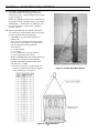
For service or repairs to boiler, call your heating contractor. When seeking information on boiler,
provide Boiler Model Number and Serial Number as shown on Rating Label.
Boiler Model Number
_V11_ _H_
Boiler Serial Number
Installation Date
64_ _ _ _ _ _
Heating Contractor
Type Firing
Address
Phone Number
Commercial Boilers
8142621R1 - 11/12
www.burnhamcommercial.com
1
Price $5.00
2
IMPORTANT INFORMATION - READ CAREFULLY
All boilers must be installed in accordance with National, State and Local Plumbing, Heating
and Electrical Codes and the regulations of the serving utilities. These Codes and Regulations
may differ from this instruction manual. Authorities having jurisdiction should be consulted
before installations are made.
In all cases, reference should be made to the following Standards:
USA BOILERS
A. Current Edition of American National Standard ANSI/NFPA 31, “Installation of Oil
Burning Equipment”, for recommended installation practices.
B. Current Edition of National Fuel Gas Code, NFPA 54/ANSI Z223.1.
C. Current Edition of American National Standard ANSI/NFPA 211, “Chimneys, Fireplaces, Vents, and Solid Fuel Burning Appliances”, For Venting requirements.
D. Current Edition of American Society of Mechanical Engineers ASME CSD-1, “Controls and Safety Devices for Automatically Fired Boilers”, for assembly and operations of controls and safety devices.
E. All wiring on boilers installed in the USA shall be made in accordance with the National Electrical Code and/or Local Regulations.
CANADIAN BOILERS
A. Current Edition of Canadian Standards Association CSA B139, “Installation Code for Oil Burning Equipment", for recommended Installation Practices.
B. The equipment shall be installed in accordance with the current Installation Code for Gas Burning Appliances and Equipment, CSA B149, and applicable Provincial Regulations for the class; which should be carefully followed in all cases.
Authorities having jurisdiction should be consulted before installations are made.
C. All wiring on boilers installed in Canada shall be made in accordance with the Canadian Electrical Code and/or Local Regulations.
DANGER
CAUTION
Indicates an imminently hazardous situation
which, if not avoided, will result in death, serious
injury or substantial property damage.
Indicates a potentially hazardous situation which,
if not avoided, may result in moderate or minor
injury or property damage.
WARNING
NOTICE
Indicates a potentially hazardous situation which,
if not avoided, could result in death, serious injury
or substantial property damage.
Indicates special instructions on installation,
operation, or maintenance which are important
but not related to personal injury hazards.
NOTICE
This boiler has a limited warranty, a copy of which is printed on the back of this manual.
It is the responsibility of the installing contractor to see that all controls are correctly installed and are operating
properly when the installation is complete. The warranty for this boiler is valid only if the boiler has been
installed, maintained and operated in accordance with these instructions.
3
DANGER
DO NOT store or use gasoline or other flammable vapors or liquids in the vicinity of this or any other
appliance.
WARNING
Improper installation, adjustment, alteration, service or maintenance can cause property damage, personal
injury or loss of life. Failure to follow all instructions in the proper order can cause personal injury or
death. Read and understand all instructions, including all those contained in component manufacturers
manuals which are provided with the appliance before installing, starting-up, operating, maintaining or
servicing this appliance. Keep this manual and literature in legible condition and posted near appliance
for reference by owner and service technician.
This boiler requires regular maintenance and service to operate safely. Follow the instructions contained
in this manual. Installation, maintenance, and service must be performed only by an experienced, skilled
and knowledgeable installer or service agency. All heating systems should be designed by competent
contractors and only persons knowledgeable in the layout and installation of hydronic heating systems
should attempt installation of any boiler. It is the responsibility of the installing contractor to see that all
controls are correctly installed and are operating properly when the installation is completed. Installation
is not complete unless a pressure relief valve is installed into the specified tapping located at the rear of
appliance - See Section III of this manual for details.
This boiler is suitable for installation on combustible flooring. Do not install boiler on carpeting. Do not
operate on floors where heat affected material is below.
Do not tamper with or alter the boiler or controls. Retain your contractor or a competent serviceman to
assure that the unit is properly adjusted and maintained.
Clean boiler at least once a year - preferably at the start of the heating season to remove soot and scale.
The inside of combustion chamber should also be cleaned and inspected at the same time.
Have Burner and Controls must be checked at least once a year or as may be necessitated.
Do not operate unit with jumpered or absent controls or safety devices.
Do not operate unit if any control, switch, component, or device has been subject to water.
Return water cannot be lower than 135°F for prolonged periods of time. Operation under these conditions will
result in sustained condensing within the combustion chamber and potentially reduce boiler longevity.
In addition, the return water cannot be introduced into the boiler if it is more than 40°F less than the idle
boiler temperature. Continued operation under these conditions may result in premature boiler failure
through thermal shock.
Example: A boiler that has been idle for some time since the last heat demand cycle may have it’s boiler
water temperature reduced to 150°F. The return temperature from the next zone activation cannot be
less than 110°F.
If the above conditions exist, an RTC (or similar type of control system) system must be installed to
protect the boiler from sustained condensing operation and thermal shock. See separate RTC Manual,
P/N 8146382.
4
WARNING
Appliance materials of construction, products of combustion and the fuel contain alumina, silica, heavy
metals, carbon monoxide, nitrogen oxides, aldehydes and/or other toxic or harmful substances which
can cause death or serious injury and which are known to the state of California to cause cancer, birth
defects and other reproductive harm. Always use proper safety clothing, respirators and equipment when
servicing or working nearby the appliance.
This boiler contains very hot water under high pressures. Do not unscrew any pipe fittings nor attempt
to disconnect any components of this boiler without positively assuring the water is cool and has no
pressure. Always wear protective clothing and equipment when installing, starting up or servicing this
boiler to prevent scald injuries. Do not rely on the pressure and temperature gauges to determine the
temperature and pressure of the boiler. This boiler contains components which become very hot when
the boiler is operating. Do not touch any components unless they are cool.
This appliance must be properly vented and connected to an approved vent system in good condition.
Do not operate boiler with the absence of an approved vent system.
This boiler needs fresh air for safe operation and must be installed so there are provisions for adequate
combustion and ventilation air.
The interior of the venting and air intake systems must be inspected and cleaned before the start of the
heating season and should be inspected periodically throughout the heating season for any obstructions.
Clean and unobstructed venting and air intake systems are necessary to allow noxious fumes that could
cause injury or loss of life to vent safely and will contribute toward maintaining the boiler's efficiency.
This boiler is supplied with controls which may cause the boiler to shut down and not re-start without
service. If damage due to frozen pipes is a possibility, the heating system should not be left unattended in
cold weather; or appropriate safeguards and alarms should be installed on the heating system to prevent
damage if the boiler is inoperative.
This boiler is designed to burn No. 2 fuel oil, natural and/or LP gas only. Do not use gasoline, crankcase
drainings, or any oil containing gasoline. Never burn garbage or paper in this boiler. Do not convert to
any solid fuel (i.e. wood, coal). All flammable debris, rags, paper, wood scraps, etc., should be kept clear
of the boiler at all times. Keep the boiler area clean and free of fire hazards.
Always keep the oil supply valve shut off if the burner is shut down for an extended period of time.
Probe and float type low water cutoff devices require annual inspection and maintenance. Refer to
instructions in Section V, Paragraph C for inspection and cleaning instructions.
NOTICE
All V11H Series cast iron boilers are designed, built, marked and tested in accordance with the ASME Boiler
and Pressure Vessel Code, Section IV, Heating Boilers. An ASME Data Label is factory applied to each V11H
jacket, which indicates the boiler Maximum Allowable Working Pressure (MAWP). Each cast iron section is
permanently marked with the MAWP listed on the boiler’s ASME Data Label. Those values for the V11H are
as follows:
MAWP, Steam - 15 psi
MAWP, Water (USA) - 80 psi
MAWP, Water (Canada) - 50 psi
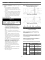
It is common and acceptable practice to install these boilers in lower pressure systems, below the boiler
MAWP. Therefore, Burnham Commercial offers safety relief valves set at or below the MAWP of the boiler.
See Table 1 for available safety relief valve set pressures.
5
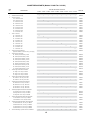
TABLE OF CONTENTS
SECTION I - GENERAL INFORMATION
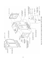
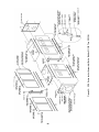
Dimensional Information ................................................................................................................................................ 8
Ratings/Data ................................................................................................................................................................... 9
Locating the Unit .......................................................................................................................................................... 10
Air Supply/Venting........................................................................................................................................................ 11
SECTION II - CAST IRON BLOCK ASSEMBLY (knockdown Only)
Assembly of Sections, Manual Draw-up ...................................................................................................................... 14
Assembly of Sections, Hydraulic Draw-up .................................................................................................................. 19
Hydrostatic Test ............................................................................................................................................................ 20
SECTION III - INSTALLATION INSTRUCTIONS
Knockdown
Canopy .......................................................................................................................................................................... 23
Flue Cover Plates .......................................................................................................................................................... 25
Rear Observation Port Cover......................................................................................................................................... 25
Inspect All Boiler Seals................................................................................................................................................. 25
Ceramic Fiber Firewall Plates....................................................................................................................................... 25
Jacket Assembly ........................................................................................................................................................... 26
Burner Mounting Plate / Burner Adapter Plate ............................................................................................................ 30
Steam Trim ................................................................................................................................................................... 31
Water Trim .................................................................................................................................................................... 33
Burner Installation ........................................................................................................................................................ 33
Package Boilers
Preparation for Installation............................................................................................................................................ 34
Common Installation Requirements
Boiler Piping - Heating Applications ........................................................................................................................... 34
Boiler Piping - Steam Applications............................................................................................................................... 42
Boiler Piping - Domestic Hot Water (DHW) Applications........................................................................................... 44
Tankless Heater Piping ................................................................................................................................................. 45
Electric Wiring............................................................................................................................................................... 46
SECTION IV - OPERATING INSTRUCTIONS
Filling System................................................................................................................................................................ 50
Adjusting Controls ........................................................................................................................................................ 50
Adjusting Burner .......................................................................................................................................................... 51
Test Controls ................................................................................................................................................................. 51
Initial Cleaning, Steam Boilers ..................................................................................................................................... 51
Initial Cleaning, Water Boilers ..................................................................................................................................... 52
Frequent Water Addition ............................................................................................................................................... 53
Oxygen Corrosion......................................................................................................................................................... 53
SECTION V - SERVICE INSTRUCTIONS
Cleaning Boiler Heating Surfaces ................................................................................................................................ 54
Maintenance of Low Water Cutoff Devices ................................................................................................................. 55
Checking Burner & Controls......................................................................................................................................... 56
Lubrication.................................................................................................................................................................... 56
General Maintenance Considerations............................................................................................................................ 56
Attention to Boiler While Not in Operation.................................................................................................................. 56
6
TABLE OF CONTENTS - Continued
SECTION VI - BURNER SPECIFICATIONS
Beckett Burners (Table VI)............................................................................................................................................57
Power Flame Burners (Table VII).................................................................................................................................58
Webster Burners (Table VIII)........................................................................................................................................61
Carlin Burners (Table IX)..............................................................................................................................................64
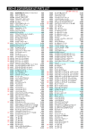
SECTION VII - REPAIR PART
Regional Office Directory............................................................................................................................................. 65
Jacket Assembly ........................................................................................................................................................... 66
Bare Boiler Assembly.................................................................................................................................................... 70
Steam/Water Trim.......................................................................................................................................................... 74
WARRANTY........................................................................................................................................................Rear Cover
7
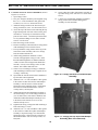
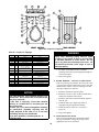
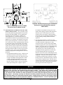
8
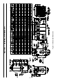
Figure 1: Dimensional Information
SECTION I - GENERAL INFORMATION
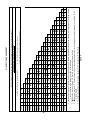
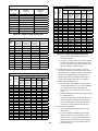
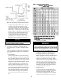
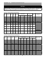
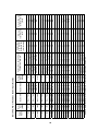
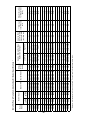
TABLE 1 - RATINGS/DATA
(2)
NET I=B=R
RATING
HEATING
SURFACE
(SQ. FT.)
SQ. FT. STEAM
STEAM MBH
WATER MBH
OIL (GPH)
GAS (MBH)
STEAM
WATER
STEAM
WATER
STEAM
WATER
VENT DIA. (INCHES)
V1104H
20.1
20.4
674
682
2106
505
593
5.8
837
64.6
74.4
7.9
0.48
59
72
2596
2704
8
V1105H
25.7
26.0
862
871
2694
647
758
7.4
1068
83.5
96.2
10.6
0.48
68
84
3076
3210
8
V1106H
32.1
32.4
1074
1085
3358
806
943
9.2
1328
102.4
118.0
13.2
0.49
77
96
3561
3720
8
V1107H
38.5
38.8
1288
1298
4036
969
1129
10.9
1588
121.3
139.8
15.9
0.5
87
108
4050
4225
10
V1108H
45.6
45.9
1525
1536
4857
1166
1335
12.9
1876
140.2
161.6
18.5
0.5
96
120
4533
4733
10
V1109H
52.0
52.3
1741
1750
5604
1345
1522
14.7
2136
159.1
183.4
21.1
0.48
105
132
5022
5247
10
V1110H
58.5
58.7
1958
1965
6333
1520
1709
16.5
2396
177
205.2
23.8
0.5
115
144
5515
5757
12
V1111H
65.0
65.2
2175
2181
7037
1689
1896
18.3
2656
195.9
227.0
26.5
0.48
124
156
5997
6263
12
V1112H
70.8
70.9
2370
2373
7668
1840
2064
19.8
2887
214.8
248.8
29.1
0.49
133
169
6482
6782
12
V1113H
76.1
76.2
2546
2552
8236
1977
2219
21.3
3103
233.7
270.6
31.8
0.47
143
181
6962
7279
12
V1114H
83.1
83.3
2781
2790
8997
2159
2426
23.3
3392
252.6
292.4
34.4
0.44
152
193
7450
7792
14
V1115H
90.1
90.5
3015
3028
9754
2341
2633
25.3
3680
271.5
314.2
37.1
0.43
161
205
7942
8309
14
V1116H
95.3
95.8
3191
3208
10323
2477
2789
26.8
3897
290.4
336.0
39.7
0.44
171
217
8432
8816
14
V1117H
102.3
103.0
3425
3447
11081
2659
2997
28.8
4186
309.3
357.8
42.4
0.46
180
229
8916
9325
14
V1118H
109.3
110.1
3659
3685
11835
2840
3204
30.8
4474
328.7
379.6
45.0
0.44
189
241
9397
9831
16
V1119H
114.5
115.5
3833
3865
12401
2976
3361
32.3
4691
346.1
401.4
47.7
0.43
199
253
9889
10338
16
V1120H
121.5
122.6
4066
4104
13154
3157
3568
34.3
4979
365
423.2
50.3
0.43
208
265
10371
10845
16
V1121H
128.4
129.7
4299
4343
13908
3338
3777
36.3
5268
383.9
445.0
53.0
0.44
217
277
10861
11360
16
V1122H
133.6
135.1
4473
4524
14471
3473
3934
37.8
5485
402.8
466.8
55.6
0.44
227
290
11347
11872
18
V1123H
140.6
142.3
4705
4763
15221
3653
4142
39.8
5773
421.7
488.6
58.3
0.45
236
302
11831
12381
18
BOILER MODEL
WATER MBH
BOILER
WATER
WEIGHT W/
CONTENT
WATER
(GALLONS)
(LBS.)
STEAM MBH
BURNER
INPUT
WATER BHP
GROSS
OUTPUT
STEAM BHP
BOILER
HORSE
POWER
(3)
NET FIREBOX VOLUME (CU.
FT.)
PRESSURE IN FIREBOX (IN.
W.C)
(1)
(1) SUFFIX "S" INDICATES STEAM BOILER, "W" INDICATES
WATER BOILER. SUFFIX "G" INDICATES GAS–FIRED, "O"
INDICATES OIL–FIRED, "GO" INDICATES COMBINATION
GAS–OIL FIRED.
(3) BOILER RATINGS ARE BASED ON 13.0% CO 2 (OIL) AND
10.0% CO2 (NATURAL GAS) AND + .10" WATER COLUMN
PRESSURE AT BOILER FLUE OUTLET.
(2) I=B=R NET RATINGS SHOWN ARE BASED ON PIPING AND
PICKUP ALLOWANCES WHICH VARY FROM 1.333 TO 1.288
FOR STEAM AND 1.15 FOR WATER.
CONSULT MANUFACTURER FOR INSTALLATIONS HAVING
UNUSUAL PIPING AND PICKUP REQUIREMENTS, SUCH
AS INTERMITTENT SYSTEM OPERATION, EXTENSIVE PIPING
SYSTEMS, ETC.
THE I=B=R BURNER CAPACITY IN GPH IS BASED ON OIL HAVING
A HEAT VALUE OF 140,000 BTU PER GALLON.
9
RATINGS SHOWN ABOVE APPLY AT ALTITUDES UP
TO 1000 FEET ON OIL AND 2000 FEET ON GAS. FOR
ALTITUDES ABOVE THOSE INDICATED, THE RATINGS
SHOULD BE REDUCED AT THE RATE OF 4% FOR EACH
1000 FEET ABOVE SEA LEVEL.
SAFETY (RELIEF) VALVE SET PRESSURE:
USA BOILER
CANADIAN BOILER
STEAM - 15 PSI
STEAM - 15 PSI
WATER - 50 PSI
WATER - 50 PSI
OPTIONAL WATER - 30 PSI
OPTIONAL WATER - 30 PSI
- 80 PSI
SECTION I - GENERAL INFORMATION (continued)
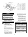
A. INSPECT SHIPMENT carefully for any signs of
Table II: Minimum Installation Clearances To
Combustible Materials (Inches)
damage.
1. ALL EQUIPMENT is carefully manufactured,
inspected and packed. Our responsibility ceases
upon delivery of crated Boiler to the carrier in good
condition.
2. ANY CLAIMS for damage or shortage in shipment
must be filed immediately against the carrier by the
consignee. No claims for variances from, or shortage in orders, will be allowed by the manufacturer
unless presented within sixty (60) days after the
receipt of goods.
Boilers with Top Flue Outlet
B. LOCATE THE UNIT
NOTICE
Recommended clearance for service may be
reduced to minimum clearance to combustible
material.
However, increased service and
maintenance difficulty will result.
Boilers with Rear Flue Outlet
1. RECOMMENDED SERVICE CLEARANCE
- Locate the unit in the boiler room so as to
provide ease of venting and adequate clearance
for maintenance, serviceability, and installation of
piping. Refer to Figure 1 for boiler dimensional
data.
A
B
C
D
E
Above
Front
Rear
Sides
Vent Connector
6
24
6
6
18
* See Table III for recommended service clearance
to access rear of boiler.
FRONT --- Provide 54" service clearance for
removal, maintenance, and servicing of burner and
controls.
REAR --- Provide a minimum service clearance
from the boiler jacket for access to pressure relief
door, flame observation port, rear flue damper and
vent piping, relief valve, and boiler return piping.
See following chart.
LEFT SIDE --- Provide a minimum clearance from
the boiler jacket of 36" for cleaning of flueways.
RIGHT SIDE --- Less Tankless Heater - Provide a
minimum clearance from boiler jacket of 12".
With Tankless Heater - Provide a minimum
clearance from the boiler jacket of 35" for
installation and removal of tankless heater(s).
TOP --- Provide a minimum clearance from the
boiler jacket of 24".
NOTE 1: L i s ted clea ranc e s c o mply wi th A meri c an
Na ti ona l Sta nda rd A NS I/NF PA 3 1, Insta llati o n of Oi l
B urni ng E qui p me nt.
NOTE 2 : V 11 S e ri es bo i le rs c a n b e i ns talle d i n roo ms
wi th clea ranc es from c o mb usti b le ma teri a l as li s te d
a bo ve . L i s te d c le ara nc e s c a nno t be re duc e d fo r a lc ove
o r c los e t i ns ta lla ti o ns.
NOTE 3 : F or re duc e d c le ara nce s to c ombus ti ble
mate ri al, p rote c ti on mus t be p rovi de d a s d es c ri be d i n
the a bo ve A NS I/NF PA 31 sta nda rd.
Table III: Recommended Rear Service Clearance
F lue
Outle t
S i ze
2. FOR MINIMUM CLEARANCES to combustible
materials, See Table II.
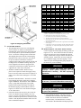
3. PROVIDE ADEQUATE FOUNDATION for the
unit. Refer to Figure 2.
Re a r F lue Outle t
C o m b us ti b le
S urfa c e s
No n-C o mb us ti b le
S urfa c e s
8" D ia.
42"
27"
10" D i a.
45"
30"
48"
33"
49"
34"
16" D i a.
52"
37"
18" D i a.
54"
39"
12" D i a.
14" D i a.
10
To p
F lue
Outle t
18"
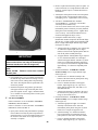
Figure 2: Boiler Foundation
permanent openings, one in or near the top of
the room and one near the bottom. The openings
shall communicate by means of ducts, with the
outdoors or to such spaces (crawl or attic) that
communicate with the outdoors.
i. Where communicating by means of vertical
ducts, each opening shall have a free area of
not less than 1 sq. in. per 4,000 Btuh (35 sq.
in. per gph.) (5.5 cm2 per kw) of total input
rating of all appliances in the enclosure.
ii. If horizontal ducts are used, each opening
shall have a free area of not less than 1 sq.
in. per 2,000 Btuh (70 sq. in. per gph.) (11
cm2 per kw) of total input of all appliances
in the enclosure.
WARNING
Boiler is suitable for installation on combustible
floor. Do not install boiler on carpeting.
Floor construction should have adequate load
bearing characteristics to bear the weight of
the boiler filled with water (see Table 1). A
boiler foundation similar to the one shown in
Figure 2 is recommended if the boiler room
floor is weak or uneven or if a water condition exists.
4. PROVIDE AIR SUPPLY AND
VENTILATION to accommodate proper
combustion.
5. CHIMNEY OR VENT
WARNING
NOTICE
Failure to supply adequate air to the boiler will
result in unsafe boiler operation.
When a V11H gas fired boiler is connected to a
venting system that is designed so that it will
operate under a negative pressure, the use of
Type C, B, or other manufactured vent systems
designed for negative pressure is acceptable.
For commercial and industrial equipment,
permanent facilities for supplying an ample amount
of outside air shall be provided in accordance with
the following.
For boiler rooms adjacent to outside walls, and
where combustion air is provided by natural
ventilation from the outside, there shall be a
permanent air supply inlet having a total free area of
not less than 1 sq. in. per 4,000 Btu per hr. (35 sq.
in. per gal. per hr.) (5.5 cm2 per kw.) of total input
rating of the burner or burners and in no case less
than 35 sq. in. (0.425 m2).
For boiler rooms not adjacent to outside walls,
the combustion air shall be supplied in a manner
acceptable to the authority having jurisdiction.
a. In the absence of local requirements, the
confined space shall be provided with two
When a V11H oil fired or combination gas/oil
fired boiler is connected to a venting system
that is designed so that it will operate under
a negative pressure, the use of Type C, L or
other manufactured vent systems designed
for negative pressure is acceptable.
Unlined masonry chimneys are not acceptable. Lined masonry chimneys are acceptable
with the appropriate vent connectors using
materials described above.
11
WARNING
When a V11H gas fired boiler is connected
to a venting system that is designed so that
it will operate under a positive pressure,
manufactured vent systems, designed and
approved for positive pressure application per
UL1738, must be used (for example, Van-Packer
model CS, Protech Model FasNSeal / FasNSeal
W2, Heatfab Saf-T-Vent or equivalent).
When a V11H oil fired or combination gas/oil
fired boiler is connected to a venting system
that is designed so that it will operate under a positive pressure, manufactured vent
systems, designed and approved for positive pressure application, must be used (for
example, Selkirk Metalbestos Model PS / IPS,
Van-Packer Model ES or equivalent).
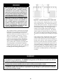
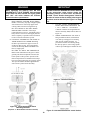
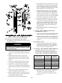
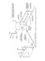
Figure 3a: Typical Arangement For Stub Vent
The V11H Series boiler is designed for forced draft
firing and may be used with a conventional natural
draft stack (15’ minimum height) or a stub vent,
sometimes called a diesel stack (see Figure 3a). See
Table I for the proper vent outlet size. For low
silhouette vent terminations, see Figure 3b. Draft
controls are not normally required, although they
may be used on installations where a natural draft
stack is used or on multiple boiler installations
with a common stack. The boiler is provided with
a breeching damper, which should be adjusted to
maintain a positive pressure of 0.1” W.C. in the vent
connector box during burner high fire operation (see
breeching pressure sensing port in Figure 1).
If the venting system is designed for positive or forced
draft venting, the boiler, vent connector and stack will
operate under positive pressure. Gas tight vent systems
designed for pressure systems must be used to prevent
flue by-product leakage. The vent height is usually
limited to prevent negative draft, typically three (3)
feet above the roof line (see Figure 3a). The damper
shall be adjusted to maintain a positive pressure of 0.1”
W.C. in the vent connector box during burner high fire
operation (see breeching pressure sensing port in Figure
1).
If the venting system is designed for negative pressure
(natural draft), the boiler still operates with positive
pressure in the chamber and up to the fixed damper on
the flue collar. However, if the venting system is larger
than what is required, the stack will provide a surplus
draft (or negative pressure) that may require the use of
a barometric damper to maintain the positive 0.1” W.C.
pressure at the flue outlet. Multiple forced draft boiler
stacks should always be designed as negative to ensure
the products of combustion do not exit a boiler that is
not firing.
WARNING
Venting instructions are recommendations only. Consult a venting expert on the design of a specific
vent system for your application. The ASHRAE Venting Guide and The National Fuel Gas Code, NFPA 54
should be considered in all venting systems.
Conventional vent material may not e suitable for the application. Flue gases can leak carbon monoxide
from the joints on these materials and can result in severe personal injury or death.
Installations having long horizontal runs or an excessive amount of tees or elbows will restrict the flow
of combustion gases and can result in condensation, flue gas leakage of carbon monoxide, resulting in
severe personal injury or death.
12
A
B
RAIN CAP
RIGHT
C
"A" CAP
RIGHT
TEE TYPE
RIGHT
D
E
WRONG
WRONG
90°
ELBOW
UP or DOWN
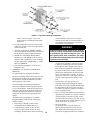
VENT SIZING - Area must be the same as or greater than the boiler breeching (Smoke Outlet). A barometric damper may be required on
installations with a high draft condition.
FAULTY BOILER BURNER OPERATION
1.If improper vent is suspected, remove pipe at breeching and operate boiler. This will determine if excessive down draft, blocked or restricted flue, etc. is causing the problem.
2.If using type shown in A above, be sure cap is raised sufficiently above main pipe to allow flue gases to vent unimpeded.
3.A popular type cap is shown in B.
4.The tee is frequently used as shown in C.
5.D and E should not be used due to possible fluctuations in back pressure.
Figure 3b: Vents — Faults & Suggestions
Typical Vents that are used on Forced Draft Boilers, on Low Silhouette Buildings
13
SECTION II - CAST IRON BLOCK ASSEMBLY
A. FACTORY ASSEMBLED SECTIONS - The
assemblage should be set in the proper location as
outlined in Section I. Lifting arrangement and weights
are given in Figure 4.
THEN THE DRAW-UP ROD NUTS SHOULD BE
LOOSENED UNTIL FINGER TIGHT AND THEN
TIGHTENED ½ TURN WITH A WRENCH. Now
proceed to Paragraph C of this section, “HYDROSTATIC TEST”.
B. FIELD ASSEMBLED SECTIONS - If the boiler
was ordered to be field assembled, follow the assembly
procedure outlined on the following pages.
1. ASSEMBLY OF SECTIONS (MANUAL
DRAW-UP)
These sections are designed to be drawn together
one section at a time using the 11" long draw-up
rods (provided) and ordinary hand tools.
Tools required:
(1) ¾" Drive Ratchet
(1) 1¼" Socket
(1) 1¼" Combination or Open End Wrench
(1) Can Thread Cutting Oil or Grease
WHEN ASSEMBLING SECTIONS WITHOUT
HYDRAULIC DRAW-UP EQUIPMENT,
NEVER ASSEMBLE MORE THAN ONE
SECTION AT A TIME.
a. Place the rear section in its approximate final
position, as outlined in Section I and support it
with a suitable prop. See Figure 5.
Figure 5: Positioning of Back Section
Figure 4: Lifting Instruction
14
b. On sizes 1104 thru 1106 only - Open target wall
carton, apply silastic to back of target wall and
secure target wall to rear section.
c. Clean the groove in the ground joint along the
edge of the section with the wire brush.
d. Open the Boiler Assembly Carton(s) and remove
the bottle of adhesive. Using the dauber supplied
in the bottle, apply the adhesive to the groove.
Be sure to use enough adhesive to sufficiently
coat the entire groove surface. If so desired,
a multi-purpose spray adhesive (supplied by
others) may be used instead. HOWEVER,
GREAT CARE MUST BE TAKEN TO
ENSURE THAT THE ADHESIVE DOES
NOT COME IN CONTACT WITH THE
NIPPLES OR NIPPLE PORTS.
e. While the adhesive is becoming tacky, clean the
nipples and nipple ports thoroughly with a degreasing solvent. Use the Loctite #592 supplied
to lubricate the nipples and nipple ports. Apply
the lubricant to the nipples and nipple ports,
then use a brush to disperse it evenly around the
nipples and nipple ports. Use approximately 25
ml of Loctite #592 per flueway [(1) 7" and (2) 3"
nipples and their (6) corresponding nipple ports].
f. Drive nipples squarely into section using
block of wood and hammer, or preferably, an
aluminum head hammer. Burnham Commercial
offers a polyethylene block for setting the
nipples (part no. 8052601). Place block over
entire nipple edge and hit the wood with the
hammer.
droop or hang outside of the groove. When the
end of the groove is reached, cut off the excess
rope. Push the length of the excess rope into
the groove at the top corner of the section face
end of the groove is reached, cut off the excess
rope. Push the length of the excess rope into
the groove at the top corner of the section face
(opposite of the 7" nipple port). Cut off and
discard any remaining rope after groove is filled.
See Figure 7.
i. From the "Section Arrangement" chart, select
the next section according to the "Identification
Code" at the top of the chart. See Figure 8.
WARNING
Figure 6: Setting of Nipples
Nipples must be driven in evenly and to the
proper depth to assure tight joints. Most
nipple leaks are caused by tilted or cocked
nipples.
DO NOT use steel/iron head hammer to
drive nipples without using a wood block.
Nipple damage may result.
g. A special nipple setting gauge is provided for the
nipples. Gauge nipple at 90° angles to insure
that it is driven to the proper depth into the
nipple opening (nipple port). Cut-out in gauge
must rest on nipple, with the legs of the gauge
touching finished face of section, when nipple is
properly driven. See Figure 6.
h. Remove a 127" length of fiberglass rope from
the assembly carton. Starting with the area
around the upper 7" nipple port, firmly press
the rope into the groove, so that the adhesive
holds it in place. (If more than 25 minutes have
passed since the adhesive was applied, it may be
necessary to reapply.) Continue to affix the rope
to the groove in this fashion around the perimeter
of the section. Make sure that the rope does not
15
Figure 7: Affixing the Fiberglass Rope
16
CT
C
F
F
F
F
V1119H
V1120H
V1121H
V1122H
uCT
uCT
u CT
uCT
uCT
uCT
uCT
uC
uC
uC
C
uC
C
uC
C
uC
C
uC
uC
uC
C
C
C
B
B
CT
CT
C
C
C
C
C
C
C
CT
CT
CT
u CT
u CT
u CT
u CT
u CT
u CT
u CT
u CX
u CX
uC
CXl
CXl
CXl
CXl
CXl
CXl
CXl
CT
CT
CT
u CT
u CT
CT u CX CT
C
u CT
u CT
C
u CT
u CT
u CT
CT
CT
CT
B
uC
uC
uC
uC
uC
uC
uC
uC
uC
u CX
CX
uC
CX
C
C
B
C
C
C
C
C
C
Cn
C
Cn
Cn
u CT
u CT
CT
CT
B
CT
CT
CT
Cn
CT
Cn
Cn
CX
CX
C
C
C
C
B
u CT
u CT
u CT
uC
uC
uC
uC
B
CX u Cn
CX u Cn
CX u Cn
CX u Cn
CX
C
C
CT
CT
CT
CT
C
B
B
uC
uC
C
C
C
C
C
C
C
CT
B
C
u CT CX
u CT CX
u CT
u CT
C
u CT CX
u CT CX
CX u CT
CX u CT
CT
CT
CT
B
u CT
u CT
u CT
u CT
u CT
u CT
u CT
B
C
CX
CX
C
C
C
B
u CT
u CT
u CT
u CT
u CT
B
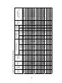
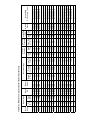
C = CENTER SECTION
CX = CENTER SECTION WITH 4" SUPPLY TAPPING
CT = CENTER SECTION WITH TANKLESS HEATER OPENING
u CT
u CT
B
CX u CT
CX u CT
C
C
C
B
C
C
B
u CT B
u CT C
B
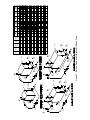
Figure 8
V1123H F
C
C
C
CT CX u Cn C
C
B
uCT
u CT CXl u C
u CT C u CT
NOTES: 1. Chart depicts steam boiler with maximum number of 'CT' Sections.
2. (u) Denotes location of Center Section to which Canopy 'J' Bolts are attached to lugs on the casting. If a lug is broken or missing, casting
must be relocated to an alternate location in the assembly.
3. (l) Denotes location of Single 'CX' Center Section required on water boilers.
4. (n) Denotes location of 'C' Center Section to which jacket support brackets must be attached during block assembly, see Figure 10 for
bracket details.
5. For boilers less tankless water heaters, replace the 'CT' Sections with 'C' Sections.
C
C
C
C
C
CT
C
CT
F
F
V1113H
CT
V1118H
F
V1112H
CT
F
F
V1111H
CT
V1117H
F
V1110H
CT
F
F
V1109H
CT
V1116H
F
V1108H
CT
CT
F
F
V1107H
V1115H
F
V1106H
CT
F
F
V1105H
CT
V1114H
F
V1104H
F = FRONT SECTION WITH 4" SUPPLY TAPPING
B = BACK SECTION WITH 4" SUPPLY TAPPING
BOILER SECTION IDENTIFICATION CODE
IMPORTANT: THE SECTIONS MUST BE ASSEMBLED ACCORDING TO THE ARRANGEMENT LISTED BELOW TO ENSURE PROPER OPERATION.
PROPER ASSEMBLY OF JACKET AND PROPER ALIGNMENT OF PIPING WITH JACKET KNOCKOUTS.
V11H SECTION ARRANGEMENT
NOTICE
The sections must be assembled according to the
arrangement shown to ensure proper operation,
proper assembly of canopy, jacket and alignment
of piping and tankless heaters with jacket
knockouts. Start with the back section and work
towards the front.
Use a brush to clean the groove in the face of
the next section. Then, using a cartridge of RTV
6500 or RTV 736 sealant in a caulking gun, fill
the groove in this section with the silastic sealant.
Touch-up any missed spots before draw-up.
Touch-up after draw-up has no value.
WARNING
This is a forced draft fired boiler and sealant must
be applied where specified for proper and safe
performance. Burnham Commercial has approved
section joint sealants (silastics) manufactured
by Dow-Corning under the product number RTV
736, and Sil-Bond under the product number RTV
6500.
Figure 9: Connection Inspection Locations and
Manual Draw-Up Tie Rod Pattern
CAUTION
To avoid damage to the draw-up rod threads while
drawing up sections, apply oil or other lubricant
to tie rod threads while assembling sections to
prevent stripping of threads on rod and to make
assembling easier.
WARNING
Sections must be drawn-up tight immediately
after properly applying sealant for best results.
Although sections may be joined within two
(2) hours of applying sealant, humidity and
temperature affect cure time. If a "thick skin"
has been formed on the sealant bead, remove
and re-apply sealant.
l. DRAW UP SECTION SLOWLY AND
EVENLY using an alternating pattern starting
with the upper right lug (closest to the 7" port)
and proceeding to the lower left , lower right
and finishing with upper left lug. When you
start, grind surfaces between adjoining sections
should be approximately 3/8” apart. Use
three (3) or four (4) passes at tightening the
four (4) draw-up rods a little at a time so that
sections are pulled up evenly. During the last
pass, pay close attention to the silastic sealant
as it squeezes when the sections come in close
contact. The silastic sealant should continue
to squeeze out wafer thin until the sections are
connected metal to metal. If the silastic has
stopped squeezing out from the connection and
the sections still do not appear to be drawn metal
to metal, use a feeler gauge to measure any gaps
at the locations identified in Figure 9. (Unless
specified otherwise, gaps should be measured at
these locations on both sides of the sections). A
maximum gap of .025" is acceptable. Measure
gaps at the outer edge of the connection only,
making sure not to puncture the gasket created
by the silastic and rope.
Sealant must be properly applied to ALL boiler
joints. Failure to properly seal the boiler joints
will result in combustion gas leaks through the
joint. DO NOT operate boiler with combustion
gas leaks.
j. Clean and lubricate nipple ports on next section
to be assembled and place on nipples previously
installed in rear section. To facilitate assembly,
it is advisable to enter the upper nipple first in
its port. Then enter the lower nipples in their
respective ports. If necessary, place a lifting bar
(crowbar) under the center of the section and
lift the nipple port onto the upper nipple. Drive
section in place with a heavy block of wood,
striking blows as squarely as possible over nipple
ports.
k. Large draw-up rod lugs with dual holes are cast in
the four corners of each casting. STARTING WITH
THE UPPER HOLES, install four 3/4" x 11"
long draw-up rods along with washers and nuts
(see Figure 9).
17
WARNING
IMPORTANT
When tightening the draw-up nuts, DO NOT
EXCEED 165 FT - LB. OF TORQUE. If the maximum
torque limit has been reached and a gap greater
than .025" still exists between the sections,
consult the sales representative.
JACKET SUPPORT BRACKETS must be attached
to the appropriate center section during the
assembly process on boiler sizes V1113H thru
V1123H. Check "Section Arrangement" Chart for
location of center section to which jacket support
brackets must be attached (see Figure 8 on Page
16).
KEEP NIPPLES ALIGNED WITH NIPPLE
PORTS. If necessary, tap edge of nipples lightly
with a blunt tool or rod to keep nipples from
cocking while sections are being drawn-up.
DO NOT DRAW UP SECTION WHEN
NIPPLES ARE COCKED. If the torque
required becomes excessive, periodically place a
heavy block of wood over each nipple port and
strike as squarely as possible with several blows
to relieve tension on the draw-up rods.
m.CONTINUE ASSEMBLING SECTIONS IN
THEIR RESPECTIVE ORDER alternating
the draw-up rods from the upper to lower set
of holes in draw-up lugs. Be certain that all
sections are drawn up iron-to-iron at all
three (3) nipple ports.
BE SURE TO APPLY THE FIBERGLASS
ROPE AND SEALANT to the grooves in the
ground joints between adjacent sections as the
boiler operates with a positive pressure in the
firebox and products of combustion will escape
between sections unless they are properly sealed.
The rope and sealant should be applied before
each section is placed on the assembly.
i.
LOCATE JACKET INTERMEDIATE
PANEL MOUNTING BRACKETS NO.
1, NO. 2 AND NO. 3 IN JACKET
CARTON. Brackets are shipped flat and
must be formed by hand, bend as shown in
Figure 10.
ii. WHEN APPROPRIATE SECTION is
being assembled to block, slide brackets
over draw-up rod lugs prior to inserting
draw-up rods, washers and nuts. To
prevent the brackets from turning during
the draw-up process, insert a large punch
or draw-up rod through second hole in each
Figure 11: Bracket Placement
Figure 10: Jacket Intermediate Panel
Mounting Brackets
(Required on Boiler Models V1113H thru V1123H)
Figure 12: Bracket Attachment to Center Section
18
Figure 13: Hydraulic Draw-Up of Sections
bracket. Refer to Figures 11 and 12 for
proper location of each bracket and typical
attachment.
sections should be spaced 1/4" to 3/8" apart.
Spacing of more than 3/8" will limit number of
sections that can be drawn up in one unit and
could indicate cocked nipples.
n. If a joint springs apart it must be re-drawn tight
within four (4) hours of the time of application of
Silastic to that joint.
o. EXCESS LENGTH OF DRAW-UP RODS
must not extend beyond front and rear sections to
ensure proper fit of jacket, adjust accordingly.
p. AFTER ALL SECTIONS HAVE BEEN
DRAWN UP, THE DRAW-UP ROD NUTS
SHOULD BE LOOSENED UNTIL FINGER
TIGHT AND THEN TIGHTENED ½ TURN
WITH A WRENCH.
q. Now Proceed to Paragraph C of this section,
Hydrostatic Test.
WARNING
Sealant must be properly applied to ALL grooves.
Failure to properly seal the boiler joints will result
in combustion gas leaks through the joint. DO
NOT operate boiler with combustion gas leaks.
The sealant should be applied before each section
is placed on the assembly.
2. ASSEMBLY OF SECTIONS (HYDRAULIC
DRAW-UP)
V1104H through V1112H Section Assemblies
The entire assemblage may be drawn-up at one time
using the hydraulic draw-up equipment providing
the operation is completed within four (4) hours
after application of the sealant.
V1113H through V1123H Section Assemblies
The total assemblage should be first drawn-up into
two (2) sub-assemblies. Each sub-assembly may be
drawn-up at one time using the hydraulic draw-up
equipment providing the operation is completed
within four (4) hours after the application of the
sealant.
"Hydraulic Draw-Up Equipment" is available
through Burnham Commercial by ordering part
number 6196008.
a. Repeat steps 1a through 1j under "Field
Assembled Sections (Manual Draw-Up)".
b. Continue driving sections in place (in their
respective order) until all sections are in the
assemblage. Ground surfaces between adjoining
19
On long boiler assemblies, it may be necessary
to draw up a partial block if the entire boiler is
not ready to be drawn up tight within four (4)
hours of the first application of the Silastic. If
the block assembly time extends overnight, the
partial block completed must be drawn up tight
before leaving the boiler overnight. If a joint
springs out, it must be re-drawn tight within four
(4) hours of first application of Silastic to the
joint.
c. Insert the three 3/4" draw-up rods (and
couplings, if appropriate) through the tapped
holes in the rear section extending them through
the tapped holes in the front section. Be sure to
screw draw-up rods into couplings far enough to
prevent stripping threads.
d. Place a 12" long steel channel on each end of the
upper draw-up rod and an 8½” long steel channel
on each end of the lower draw-up rods. Install
nuts and washers on one end of the draw-up rods
and the hydraulic rams, washers and draw-up rod
clamps on the other. See Figure 13.
e. Draw-Up Sections
Use hydraulic rams to draw up sections by
applying pressure alternately on the draw-up
rods. When rams reach stroke limit, release
pressure in ram pumps and then move clamps to
new position.
CAUTION
Do not apply pressure directly on threaded
tappings on front and rear sections with draw-up
channels during assembly procedures.
Rods should be approximately centered in
openings so that rods and couplings (when
used) do not drag on pipe thread in end section
tappings.
WARNING
READ THE STATEMENTS BELOW BEFORE
ATTEMPTING TO USE HYDRAULIC EQUIPMENT.
• Release pressure in ram pumps before
attempting to remove clamps.
• Do not stand in line with draw-up rods at
either end when hydraulic pressure is being
applied. As a safety measure, ends of drawup rods should be covered while sections are
being drawn in case rods should snap while
under tension.
• Do not operate ram against draw-up
coupling.
• Do not operate pump after ram has reached
stroke limit.
Figure 14: Boiler Section Assemblage
Brackets are shipped flat and must be formed
by hand, bend as shown in Figure 10.
ii. Slide brackets over draw-up rod lugs prior
to inserting the 11" long tie rods, washers
and nuts. Refer to Figures 11 and 12 for
proper location of each bracket and typical
attachment method.
h. Excess length of draw-up rods must not extend
beyond front and rear section to ensure proper fit
of jacket, adjust accordingly. TIGHTEN ALL
TIE ROD NUTS UNTIL FINGER TIGHT.
THEN TIGHTEN THEM AN ADDITIONAL
½ TURN WITH A WRENCH.
f. Continue to draw-up until all sections make
contact at the ground joints.
g. After all sections have been drawn up, but before
removing the hydraulic rams and draw-up rods,
the 11" long tie-rods must be installed.
Large draw-up rod lugs with dual holes are cast
in the four (4) corners of each casting. Starting
with the upper holes in the back section, install
four (4) ¾" x 11" long tie rods along with
washers and nuts. Continue installing the tie
rods alternating from the upper to lower set
of holes in draw-up lugs until front section is
secured. Be certain that all sections are drawn up
iron to iron at all three nipple ports.
C. HYDROSTATIC TEST - After the boiler sections
have been assembled, it is essential that the boiler be
hydrostatically tested before the canopy, flue cover
plates, jacket, or piping is installed.
1. Tankless Heater Installation
IMPORTANT
2. Plug all boiler tappings and fill entirely with cold
water.
Jacket Support Brackets must be attached to the
appropriate center section during this process.
Check "Section Arrangement" chart for location
of center section to which jacket support brackets
must be attached (see Figure 8).
i.
LOCATE JACKET INTERMEDIATE
PANEL MOUNTING BRACKETS
NO. 1, NO. 2, AND NO. 3 IN JACKET
CARTON. Brackets are shipped flat and
must be formed by hand, bend as shown in
Figure 10.
If boiler is ordered with tankless heaters, install
heaters with the gaskets provided. Table V gives
the maximum number of heaters permissible per
assemblage and the heater ratings.
CAUTION
DO NOT install gauge until after hydrostatic
testing the boiler. Gauge failure may result.
3. All completed boilers shall satisfactorily pass the
prescribed hydrostatic test.
a. STEAM BOILERS: The assembled boiler shall
be subjected to a hydrostatic test of not less than
45 psig.
20
4. EXAMINE BOILER CAREFULLY, INSIDE AND
OUTSIDE, to insure against leaks from cocked
nipples or through concealed breakage caused in
shipping and handling. This precaution is for your
protection and will simplify handling of necessary
replacements and adjustment claims.
b. HOT WATER BOILERS: The assembled boiler
shall be subjected to a hydrostatic test of not less
than 1½ times the maximum allowable working
pressure, as established by the relief valve
provided with the boiler. For example, a boiler
with a 50 psi relief valve must be subjected to a
test pressure of 75 psig to 85 psig.
5. After making certain that there are no leaks, drain
boiler and remove plugs for boiler trim and other
connections.
WARNING
Failure to properly hydrotest all boilers at the
correct pressure may result in section assembly
failure in operations.
21
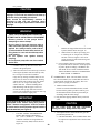
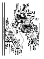
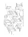
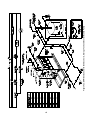
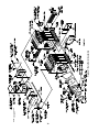
22
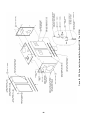
NOTE: Flue top insulation
not shown.
Figure 15: Bare Boiler Assembly
SECTION III - INSTALLATION INSTRUCTIONS
SECTION III - INSTALLATION INSTRUCTIONS (continued)
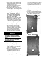
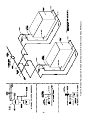
A. CANOPY/FLUE OUTLET ASSEMBLY, Refer to
15.Secure either the top flue outlet damper assembly or top outlet canopy cover with #10 x 1/2" sheet metal screws.
Figures 15, 16 and 17.
1. Open canopy carton.
16.1" thick piece of fiberglass insulation provided in canopy carton will be installed during jacket assembly, set aside until then.
2. Two piece canopies should be joined together using
the 1/8" x 1" wide self-adhesive fiber gasket and
seventeen (17) #10 x 1/2" sheet metal screws.
3. Attach the canopy bracket to the front end cap of
canopy with four (4) #10 x 1/2" sheet metal screws.
4. Across the top of the front section and along the top
ledges running back each side of the sections, place
continuous 2" wide strips of cerafelt and overlap
joints at front corners. Cerafelt strip should extend
1/4" beyond raised flange on rear surface of back
section. Cut off excess.
5. Place the canopy on the sections.
6. Position rear flange (end with studs) of canopy flush
with raised flange on rear of back section.
7. Loosely attach the canopy bracket to the lug on the
front of the section assembly with 5/16" carriage
bolt, flat washer and lock-nut.
8. Attach canopy hold down channels to center
sections with appropriate canopy 'J' bolts. Insert
threaded end through holes in channels and hook
'J' bolts on center section lugs (hooks should face
forward). Loosely secure canopy with 5/16" flat
washers, lock washers and brass nuts.
9. Check to see if rear flange of canopy is still flush
with raised flange on back section. Tighten rear set
of canopy 'J' bolts only.
Figure 16: Canopy with Rear Flue Outlet Damper
Assembly
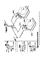
10.Open either the rear flue outlet carton (standard) or top flue outlet carton (optional).
11.Attach the 1/8" x 1" wide self-adhesive fiber gasket to the surface of either the rear flue outlet damper assembly or rear flue outlet cover that mounts against the canopy and back section. Gasket must be centered over all attachment holes. Do not overlap corners, cut butt joints.
12.Attach either the rear flue outlet damper assembly or rear outlet canopy cover to the canopy with the six (6) 5/16" flat wasters, lock-washers and brass nuts. Attach the rear flue outlet damper assembly or cover to the back section with the six (6) 5/16" flat washers and cap screws.
13.Tighten front canopy carriage bolt and remaining 'J' bolts until canopy is secure.
14.Attach the 1/8" x 1" wide self-adhesive fiber gasket to the surfaces of either the top flue outlet damper assembly or top outlet canopy cover that mounts against the canopy. Gasket must be centered over all attachment holes. Do not overlap corners, cut butt joints.
Figure 17: Canopy with Top Flue Outlet Damper
Assembly (Rear Cover Removed)
23
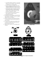
Important Product Safety Information
Refractory Ceramic Fiber Product
Warning:
The Repair Parts list designates parts that contain refractory ceramic fibers
(RCF). RCF has been classified as a possible human carcinogen. When
exposed to temperatures about 1805°F, such as during direct flame contact,
RCF changes into crystalline silica, a known carcinogen. When disturbed as a
result of servicing or repair, these substances become airborne and, if inhaled,
may be hazardous to your health.
AVOID Breathing Fiber Particulates and Dust
Precautionary Measures:
Do not remove or replace RCF parts or attempt any service or repair work
involving RCF without wearing the following protective gear:
1. A National Institute for Occupational Safety and Health (NIOSH)
approved respirator
2. Long sleeved, loose fitting clothing
3. Gloves
4. Eye Protection
• Takestepstoassureadequateventilation.
• Washallexposedbodyareasgently with soap and water after contact.
• Washworkclothesseparatelyfrom other laundry and rinse washing
machine after use to avoid contaminating other clothes.
• DiscardusedRCFcomponentsbysealing in an airtight plastic bag. RCF
and crystalline silica are not classified as hazardous wastes in the United
States and Canada.
First Aid Procedures:
• Ifcontactwitheyes:Flushwithwater for at least 15 minutes. Seek
immediate medical attention if irritation persists.
• Ifcontactwithskin:Washaffected area gently with soap and water.
Seek immediate medical attention if irritation persists.
• Ifbreathingdifficultydevelops:Leavetheareaandmovetoalocation
with clean fresh air. Seek immediate medical attention if breathing
difficulties persist.
• Ingestion:Donotinducevomiting. Drink plenty of water. Seek
immediate medical attention.
24
8. With one hand, hold top 'J' bolt between your index
and middle fingers. With the other hand, hold flue
plate on a slight inward angle, align top hole with
end of 'J' bolt and force it through as far as possible.
Repeat similar process for bottom 'J' bolt.
9. Holding threaded end of top 'J' bolt, pull outward
and at the same time push flue cover plate against
castings. Place one finger across 'J' bolt at base of
flue cover plate hole. Place 5/16" washer, split lock
washer and brass nut on end of 'J' bolt. Hand tighten
only. Repeat similar process for bottom 'J' bolt.
10. Push upward on bottom edge of flue cover plate to
eliminate sag in hardware. Tighten brass nuts with
a deep socket or wrench until insulation on cover
plate provides an adequate seal to casting. If after
tightening, a gap is still evident where the sections
join, apply silastic along top and bottom edge of
insulation board.
11. Repeat steps 2 through 10 for mounting remaining
flue cover plates.
C. MOUNT REAR OBSERVATION PORT
COVER, Refer to Figure 15.
1. Apply a ¼” bead of Silastic sealant along the groove
on the inside face of the rear observation port cover.
2. Mount the rear observation port cover onto the rear
section (with the word “Top” in the upright position)
using the (4) 5/16”-18 X 1” cap screws and washers
provided.
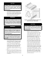
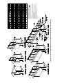
Figure 18: Flue Cover Plate Attachment
B. INSTALL FLUE BAFFLES AND COVER
PLATES into cleanout openings on left side of boiler
as shown in Figure 18.
D. INSPECT SEALS
1. A visual inspection should be made of all sealed
joints and repairs made if necessary. A darkened
boiler room with a light source in the combustion
space and canopy will aid this inspection.
WARNING
See Important Product Safety Information on Page
24 of this manual, regarding refractory ceramic
fiber product warning.
E. INSTALL THE CERAMIC FIBER FIREWALL
PLATES on the right side of the center sections
starting at the front and working toward the back, see
Figure 15 and 19. Firewall plates are shipped in the
canopy carton, see chart below for quantities required.
1. Locate the flue baffle carton. Each flue opening
will get two (2) short baffles and three (3) long flue
baffles.
2. Insert the first short flue baffle, wide end first,
directly above the upper 'J' bolt attachment lug, so
that the baffle rests on the pin row directly behind
the lug.
3. Insert the second short flue baffle, narrow end first,
two (2) pin rows down from the first short baffle.
4. Insert the three (3) long flue baffles, continuing
down on every second pin row and alternating wide
and short ends, so that the end result matches Figure
18.
Boiler Model
Front
Firewall Plate
Common
Firewall Plate
V1104H & V1105H
1
0
V1106H & V1107H
1
1
V1108H & V1109H
1
2
V1110H & V1111H
1
3
V1112H & V1113H
1
4
V1114H - V1123H
1
5
1. There are two different types of firewall plates
identified as "Front" and "Common". All builds
start with one (1) "front" firewall plate and
"common" firewall plates are added as the boiler
grows in size.
5. Locate the cover plates, carriage bolts, nuts and
washers in the boiler assembly carton(s).
6. Remove insulation from two 3/8" diameter holes in
flue cover plates using a 3/8" drill bit which can be
rotated through insulation by hand.
7. Hook flue cover 'J' bolts over attachment lugs.
25
2. Remove square knockout from jacket rear panel. To
remove knockout, use a single hacksaw blade with
handle or aviation snips to cut metal tabs between
slotted holes.
3. Attach jacket front panel to front section and jacket
rear panel to back section using the eight (8) #10
self tapping screws. Tighten these screws securely.
4. JACKET INTERMEDIATE PANEL
ATTACHMENT - required on V1113H thru
V1123H jacket assemblies only.
Use two (2) sheet metal screws each to secure jacket
intermediate panels to brackets previously attached
during the section assembly process. Tighten these
screws securely. For bracket attachment refer to
Section II, Paragraph B, Step m, item i.
5. Each jacket channel has a three (3) digit
identification number stamped on the bottom flange.
The last two (2) digits identify their nominal length.
Refer to single and multiple channel usage charts,
See Figures 22 and 23.
a. Attach each jacket 'J' channel to one of the jacket
'U' channels of equal length (last two digits
match) as shown in the exploded jacket detail on
each of the jacket assembly drawings.
b. A support bracket with adjustable leg is required
on 'J'/'U' channel assemblies 46" and longer.
Attach each support bracket with three (3) sheet
metal screws and thread adjustable support leg
(1/4" cap screw) into bottom of support bracket
approximately 1" as shown in exploded jacket
detail.
6. Channel Attachment - V1104H thru V1112H
Jacket Assembly (refer to single channel usage
chart, Figure 22).
Figure 19: Firewall Plates
IMPORTANT
Models V1104H and V1106H Only. Cut-off 3/4" of
excess material from rear edge of firewall plate to
eliminate interference with rear target wall.
Model V1104H: Remove excess from front firewall
plate.
Model V1106H:
firewall plate.
Remove excess from common
2. Firewall plates have two (2) notches located along
the bottom edge which interlock with lugs cast on
each center section, making them self positioning.
The "front" firewall plate must be positioned as far
forward as possible.
3. Install firewall plates using silastic (provided) on
each upper and lower edge of firewall plate where
plate rests against section. Apply a minimum bead
of 1/2" diameter to all contact points to form a good
bond to the casting.
F. JACKET ASSEMBLY
FOR V1104H thru V1112H JACKET ASSEMBLY
DRAWING, SEE FIGURE 20.
FOR V1113H thru V1123H JACKET ASSEMBLY
DRAWING, SEE FIGURE 21.
1. Open jacket carton(s) and jacket hardware package.
Unless otherwise stated, all jacket components are
fastened with #8 x 1/2" hex head sheet metal screws.
Do not drive sheet metal screws tight until jacket
assembly is complete.
26
a. Attach each 'J'/'U' channel assembly to the
bottom of the front and rear jacket panels using
four (4) sheet metal screws.
b. On 'J'/'U' channel assemblies with support
bracket, adjust support leg (1/4" cap screw)
down until leg touches floor, then add 1/2 to 1
full additional turn.
c. Attach each remaining 'U' channel to the top of
the front and rear jacket panels ('U' side down)
using (2) sheet metal screws.
7. Channel Attachment - V1113H thru V1123H
Jacket Assembly (refer to multiple channel usage
chart, Figure 23).
a. Attach the appropriate length 'J'/'U' channel
assembly to the bottom of the front and
intermediate jacket panels using four (4) sheet
metal screws. Repeat for opposite side.
b. Attach remaining 'J'/'U' channel assemblies
between the bottom of intermediate and rear
jacket panels on each side in the same manner.
c. On 'J'/'U' channel assemblies with support
bracket, adjust support leg (1/4" cap screw)
27
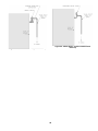
Figure 20: V11H Series Jacket Assembly (Boiler Models V1104H Thru V1112H)
28
Figure 21: V11H Series Jacket Assembly (Boiler Models V1113H Thru V1123H)
RIGHT Side Usage Chart
Single Channel Usage
'U'
Channel No.
(4 Req'd.)
'J'
Channel No.
(2 Req'd.)
V1104H
U26
J26
V1105H
U32
J32
V1106H
U38
J38
V1107H
U44
J44
V1108H
U50
Boiler Size
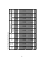
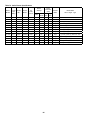
Multiple Side Panels (Front to Rear)
Boiler
Size
Single Panel No. Panel No. Panel No. Auxiliary
Panel
Right
1
2
3
Panel
No. 4
Side
Forward Rearward Forward
Auxiliary Rearward
Heater Right Side Right Side Right Side Right Side Right Side
Panel
Heater
Heater
Heater
Heater
Heater
Panel
Panel
Panel
Panel
Panel
V1104H
SRH24
---
---
---
---
---
V1105H
SRH30
---
---
---
---
---
J50
V1106H
SRH36
---
---
---
---
---
V1107H
---
FRH27
RRH15
---
---
---
V1108H
---
FRH27
RRH21
---
---
---
V1109H
---
FRH27
FRH27
---
---
---
V1109H
U56
J56
V1110H
U63
J63
V1111H
U69
J69
V1110H
---
FRH27
RRH33
---
---
---
V1112H
U75
J75
V1111H
---
FRH39
RRH27
---
---
---
V1112H
---
FRH39
RRH33
---
---
---
V1113H
---
FRH27
RRH17
FRH17
---
RRH15
V1114H
---
FRH27
RRH17
FRH17
---
RRH21
V1115H
---
FRH27
RRH17
FRH17
---
RRH27
V1116H
---
FRH33
RRH17
FRH29
---
RRH15
V1117H
---
FRH33
RRH17
FRH29
---
RRH21
V1118H
---
FRH33
RRH17
FRH29
---
RRH27
V1119H
---
FRH33
RRH29
FRH29
---
RRH21
Figure 22: Single Channel Usage Chart
Multiple Channel Usage
Boiler
Size
Front 'U'
Channel No.
(4 Req'd.)
Front 'J'
Channel No.
(2 Req'd.)
Rear 'U'
Rear 'J'
Channel No. Channel No.
(4 Req'd.)
(2 Req'd.)
V1113H
U46
J46
U34
J34
V1120H
---
FRH33
RRH29
FRH29
---
RRH27
V1114H
U46
J46
U40
J40
V1121H
---
FRH33
RRH29
FRH29
---
RRH33
V1115H
U46
J46
U46
J46
V1122H
---
FRH33
RRH29
FRH29
ARH24
RRH15
V1116H
U52
J52
U46
J46
V1123H
---
FRH33
RRH29
FRH29
ARH24
RRH21
V1117H
U52
J52
U52
J52
V1118H
U52
J52
U58
J58
V1119H
U65
J65
U58
J58
V1120H
U65
J65
U58
J58
V1121H
U65
J65
U65
J65
V1122H
U65
J65
U71
J71
V1123H
U65
J65
U77
J77
Figure 25: Right Side Panel Usage Chart
down until leg touches floor, then add 1/2 to 1
full additional turn.
d. Using two (2) sheet metal screws each, attach the
remaining 'U' channels ('U' side down) between
the tops of the front, intermediate and rear jacket
panels according to channel length.
8. Position the loose piece of 1" thick x 36" wide
fiberglass insulation, provided in the canopy carton,
against left side 'U' channel(s), across top of canopy
and down over right side between canopy and
supply piping. Remove insulation from collar on
top flue outlet damper assembly, if so equipped.
Figure 23: Multiple Channel Usage Chart
Left Side Usage Chart
Multiple Side Panels (Front to Rear)
Boiler
Size
Single
Left Side
Panel
Panel No. Panel No. Panel No.
1
2
3
Auxiliary
Panel
Panel
No. 4
Forward
Left Side
Panel
Rearward
Left side
Panel
Forward
Left side
Panel
Auxiliary
Left Side
Panel
Rearward
Left Side
Panel
V1104H
SLS24
---
---
---
---
---
V1105H
SLS30
---
---
---
---
---
V1106H
SLS36
---
---
---
---
---
V1107H
---
FLS27
RLS15
---
---
---
V1108H
---
FLS27
RLS21
---
---
---
V1109H
---
FLS27
FLS27
---
---
---
V1110H
---
FLS27
RLS33
---
---
---
V1111H
---
FLS39
RLS27
---
---
---
V1112H
---
FLS39
RLS33
---
---
---
V1113H
---
FLS27
RLS17
FLS17
---
RLS15
V1114H
---
FLS27
RLS17
FLS17
---
RLS21
V1115H
---
FLS27
RLS17
FLS17
---
RLS27
V1116H
---
FLS33
RLS17
FLS29
---
RSL15
V1117H
---
FLS33
RSL17
FLS29
---
RLS21
V1118H
---
FLS33
RLS17
FLS29
---
RLS27
V1119H
---
FLS33
RLS29
FLS29
---
RLS21
V1120H
---
FLS33
RLS29
FLS29
---
RLS27
V1121H
---
FLS33
RLS29
FLS29
---
RLS33
V1122H
---
FLS33
RLS29
FLS29
ALS24
RLS15
V1123H
---
FLS33
RLS29
FLS29
ALS24
RLS21
9. Jacket Top Panel Attachment
a. On the top flue outlet damper assembly, remove
octagon shaped knockout. To remove knockout,
use a single hacksaw blade with handle or
aviation snips to cut metal tabs between slotted
holes.
b. Remove knockout(s) for necessary supply piping
in a similar manner.
c. Attach jacket top panel(s) to the front panel, rear
panel and upper 'U' channels with sheet metal
screws. Secure seam on two piece top panel
(V1113H-V1123H) with sheet metal screws.
Figure 24: Left Side Panel Usage Chart
29
10.Install Jacket Side Panels
a. Snap black thumb hole bushings into all side
panel holes.
b. Use left side panel and right side panel usage
charts to determine correct positions of side
panels. The five (5) digit panel identification
numbers shown in the charts are also stamped
along the bottom edge of each panel. Refer to
Figures 24 and 25.
c. Forward and auxiliary panels have reverse bend
flanges on one side of panel. These panels must
be installed prior to rearward panels.
d. If boiler is equipped with tankless heaters they
should be installed at this time if they were not
installed for hydrostatic test outlined on Page 20.
e. Install left side panels into position by inserting
top of panel into upper 'U' channel, pushing
bottom of panel in toward boiler, and sliding
panel down into bottom 'J' channel.
f. Remove the knockouts necessary for tankless
heater operation on right side panels.
g. Install right side panels.
11.Combination Label and Burnham Commercial Logo Plate applied by manufacturer. If loose or peeling, apply pressure to reset adhesive.
12.Place the rating label (from Instruction envelope) over the top of front panel label that identifies the proper location.
13.On steam boilers, attach lowest permissible water level plate (from steam trim carton) to the front panel using sheet metal screws.
14.Tighten all sheet metal screws to complete jacket assembly.
Figure 26: Burner Mounting Plate and Burner
Adapter Plate
Figure 27: Burner Mounting Plate/Burner Adapter Plate Options
30
G. MOUNT BURNER MOUNTING PLATE, refer to
CAUTION
Figures 15 and 26.
Failure to properly fill all gaps between the
insulation and burner blast tube may result in
damage to the burner.
1. Install ten (10) 5/16" x 2" long tap-end studs with
the short length of threads into the boiler front
section.
2. With the use of silastic, secure the 3/16" diameter
rope gasket to the groove along the mounting plate
opening in the front section.
6. For boilers without tankless heaters, proceed to
Paragraph I (Install Steam Trim) or J (Install Water
Trim).
3. Place burner mounting plate over studs and secure
with 5/16" flat washer, lock washers and brass nuts.
7. For boilers with tankless heaters, install the
tankless heater manifolds according to Figure 28.
H. MOUNT BURNER ADAPTER PLATE TO
BURNER MOUNTING PLATE, refer to Figures 26
and 27.
ALSO, REFER TO BURNER INSTALLATION
MANUAL FOR INSTRUCTIONS SPECIFIC TO
EACH BURNER.
1. In most cases the burner adapter plate carton for
the specified burner will be provided by Burnham
Commercial. Power Flame V1122H and V1123H
burners require special adapters that will be
provided with the burner.
IM P OR TAN T
Water heater manifolds must be removable to allow for
heater repair and replacement, also for the removal of
jacket right side panels for boiler repair and inspection.
Therefore, the recommended use and placement of shut
off valves and unions on all manifold assemblies is
crucial to providing easy access for future servicing.
I. STEAM BOILERS - INSTALL STEAM TRIM
2. If adapter is provided by Burnham Commercial,
open carton and remove contents. Apply four (4)
small dabs of silastic on rear surface of adapter plate
to temporarily hold gasket in place. Hold adapter
plate in position against burner mounting plate, align
holes and secure with four (4) 3/8" lock washers and
3/8" - 16 x 7/8" lg. cap screws.
Items for steam trim are located in the steam trim
carton (except for the separately ordered low cutoff and
tankless heater control). Table IV and Figure 29 show
the proper tappings for each item.
1. Install the gauge glass set.
2. Install the low water cutoff. When using two
LWCO's on a V11H steam boiler, a probe type
LWCO cannot be used in conjunction with a float
type. See Figure 39 for illustration of two float
LWCO's. Also follow manufacturers instructions
furnished with control.
3. If adapter is furnished with burner, follow
manufacturer's instructions using gasket material
and hardware provided with burner.
a. Power Flame burners for the V1122H and
V1123H are furnished with special adapter
plates.
3. Install the Pressuretrol to the boiler using the 1/4"
x 90° (1-7/8" x 4") siphon and the 3/4" NPT x 1/4"
FPT hex bushing.
b. All other burners connect directly to the adapter
plate supplied by Burnham Commercial.
4. The Pressuretrol must be accurately leveled for
proper operation. It is level when the leveling
indicator hangs freely with its pointer directly over
the index mark inside the back of the case. Level
the controller by carefully bending the steam trap
(siphon loop).
4. USE A HOLE SAW OR KNIFE TO CUT
BURNER MOUNTING PLATE INSULATION
TO MATCH HOLE SIZE ON BURNER
ADAPTER PLATE. After cutting, remove any and
all loose pieces of insulation which may become
lodged or interfere with the head of a burner air tube
after insertion.
5. Install drain valve supplied by others in tapping B
using the appropriate bushing
6. Install the steam gauge using the 1/2" NPT x 1/4"
FPT hex bushing.
5. Confirm that hole in insulation fits snugly around
burner blast tube. If hole is oversized, remove
burner mounting plate (with burner attached) from
boiler. Use additional fiberglass rope gasket
provided with burner to fill in any space between
insulation and blast tube. If additional rope gasket
is not provided with the burner, use 3/8” fiberglass
rope rated for 2300°F (provided by others).
Reinstall burner mounting plate when finished.
7. Install the safety valve to the back section as shown
in Figure 43. The safety valve is installed in the tee
provided for blowoff piping.
31
32
Figure 28: Minimum Piping Recommendations for V11H Series Tankless Heater Manifolds
Figure 29: Purpose of Tappings
Table IV: Purpose of Tappings
TAPPING size
A
B
C
D
E1
E2
4"
3"
3"
1½"
1"
1"
F1
1"
F2
1"
G
H
J
¾"
¾"
¾"
K1
¾"
K2
¾"
L
½"
M
½"
N
¾"
P
¾"
* Special Order Only
STEAM BOILER
WATER BOILER
Supply
Return
Safety Valve
Crown Inspection / Washout *
Float L.W.C.O.
Float L.W.C.O.
Upper Auxiliary Float
L.W.C.O. Connection *
Lower Auxiliary Float
L.W.C.O. Connection
--------Firing Rate Pressure Control
Operating Pressure
Limit Control
High Pressure Limit Control/
Manual Reset
Gauge Glass
Steam Gauge (Bush to ¼")
----Low Fire Hold Control
Supply
Return
Relief Valve
Crown Inspection / Washout *
Float L.W.C.O.
Float L.W.C.O.
WARNING
Safety valve discharge piping must be piped
to within six (6) inches of floor or to floor drain
to eliminate potential of severe burns. Do not
pipe in any area where freezing could occur. Do
not install any shut-off valves, plugs or caps in
discharge piping.
---------
8. For boilers with tankless heaters, install the
operating control in an unused tapping through one
of the heater plates.
Probe L.W.C.O.
Auxiliary Probe L.W.C.O.
Firing Rate Temperature Control
Operating Temperature
Limit Control
High Temperature Limit Control/
Manual Reset
Not Used - Plug
Temperature/Pressure Gauge
Auxiliary Tapping *
Low Fire Hold Control
9. Plug extra tappings.
J. WATER BOILERS - INSTALL WATER TRIM
Items for water trim are located in the water trim carton
(except for the separately ordered low water cutoff and
tankless heater control). Table IV and Figure 29 show
the proper tappings for each item.
1. Install the temperature pressure gauge.
NOTICE
2. Install the low water cutoff. Follow manufacturers
instructions furnished with controls.
The L404 Pressure Limit contains mercury in a
sealed tube. Do not place limit in the trash at the
end of its useful life.
If this limit is replacing a limit that contains
mercury in a sealed tube, do not place your old
limit in the trash.
Contact your local waste management authority
for instructions regarding recycling and the
proper disposal of this limit, or of an old limit
containing mercury in a sealed tube.
If you have questions, call Honeywell Inc. at
1-800-468-1502
3. Install the immersion well and mount the aquastat
onto the well.
4. Install the drain valve supplied by others in tapping B using the appropriate bushing.
5. Install the pressure relief valve as shown in Figure 44.
6. Plug extra tappings.
K. BURNER INSTALLATION
Refer to burner manufacturer's installation manual
for proper installation, fuel piping, wiring, burner
adjustment and service instruction.
33
Number of
Sections
Length A
Width B *
Height
C **
V1104H
V1105H
V1106H
V1107H
V1108H
V1109H
V1110H
V1111H
V1112H
V1113H
V1114H
V1115H
V1116H
V1117H
V1118H
V1119H
V1120H
V1121H
V1122H
V1123H
4
5
6
7
8
9
10
11
12
13
14
15
16
17
18
19
20
21
22
23
71¼
77½
89½
95½
101¾
108
114
120
130¼
136½
142½
148½
154¾
161
167
173
179¼
185½
197½
203½
48
48
48
48
48
48
48
48
48
48
48
48
48½
48½
48½
48½
48½
48½
48½
48½
68
68
68
68
68
68
68
68
68
68
68
68
70
70
70
70
70
70
70
70
Approx.
Center of
Gravity D ***
22
25½
28¼
31¾
35
38½
41½
44½
47½
50¾
53¾
56¾
59¾
63
67
70
73
76¼
79¼
82¼
Approx.
Shipping
Weight LBx *
2438
2899
3360
3806
4254
4689
5129
5597
6029
6537
6880
7408
7835
8265
8691
9140
9567
10005
10429
10859
* Width can vary with gas train configuration.
** Add 6½" to dimension C when equipped with optional top outlet.
*** Varies slightly with burner and gas train configuration.
1. Do not tilt. Exercise caution when lifting to avoid damage.
2. This boiler can be lifted by fork tuck. Do not truck from front.
3. When lifting from rear, forks must extend from beyond center of gravity
and second skid cross bar.
4. When lifting from side, forks must extend to opposite skid rail and straddle
center of gravity.
5. Cablespreader is to prevent jacket damage. Spreader width should equal B
(width of skid) + 12". Adjust cable lengths to lift at approximate center of
gravity per chart.
Figure 30: Shipping Information
L. PACKAGED BOILER
1. The packaged boiler comes on its own shipping
skid (see Figure 30) and the assembled block is
hydrostatically tested at the factory. Once the boiler
is in its final position, perform another hydrostatic
test at 1½ times the working pressure of the boiler.
The shipping skid can be used as a housekeeping
pad unless local codes say otherwise. All controls
are pre-wired down to the burner. If burner is
equipped with a lead lag panel, lead lag controls will
be shipped loose for header mounting. The power
can be supplied to the burner if equipped with a
control panel. If burner has no panel, the power is
supplied to the J-box on the front jacket.
M. BOILER PIPING - HEATING APPLICATIONS
Connect supply and return piping to heating system (see
Figures 31 to 37). Flow direction for hot water boilers
must be from the rear return out through the top front
supply. Steam boilers can pipe return to the front as an
alternate location. Some boiler sizes may require the
use of additional supply and return tappings. Check
Table IV, Figure 29 and applicable piping diagram for
the boiler size you are installing.
WARNING
Failure to properly pipe boiler may result in
improper, unsafe system operation and void
manufacturer's warranty. DO NOT improperly
pipe boiler.
2. SUPPLY CONNECTIONS - Removal of top
jacket is not required to connect the supply riser(s),
however one may find it easier. Refer to Figure(s) 31
and/or 32 for water boilers and Figure 37 for steam
boilers.
NOTICE
3. RETURN CONNECTIONS - The boiler is secured
to the shipping skid with U bolts and 3" shipping
nipples. REMOVE THE BOLTS AND NIPPLES.
Using 3" plugs and an appropriate pipe sealant,
plug the unused return connections according to
the minimum piping recommendations. Refer to
Figure(s) 31 and/or 32 for water boilers and Figure
37 for steam boilers.
4. If the boiler burner unit was factory fire tested, the
burner was adjusted to approximately 10% CO2
(gas) or 13% CO2 (oil) with an overfire pressure as
listed in the Burner Specifications, Section VI of this
manual. Final adjustments should be made once the
unit is installed and adjusted.
Boiler
Number
All steam and hot water pipes must have clearances
of at least ½" from all combustible construction.
WARNING
A hot water boiler installed above radiation level
must be provided with a low water cutoff device
as part of the installation.
34
1. HOT WATER HEATING - This boiler must be
installed in strict accordance with this installation
manual Deviations from these installation
instructions may void manufacturer’s warranty.
Also consult I=B=R Installation and Piping Guides.
e. Multiple Boilers - Recommended minimum
multiple boiler piping is shown in Figure 35 as
primary secondary with a by-pass. The boiler
circulator will maintain a constant flow through
the boiler during every heat demand while the
by-pass diverts a portion of hot water back to
the return. Alternate minimum multiple boiler
piping is shown in Figure 36. The blend pump
will maintain constant flow through the boiler
during every heat demand and provide a hot
water blend back to the return.
f. Glycol Antifreeze Solutions - Many systems
today use ethylene or propylene glycol antifreeze
solutions as a measure for freeze protection, as
well as a pump lubricator and corrosion inhibitor.
The properties of the glycol mixture have an
impact on valve and pump sizing. All glycol
solutions have a lower specific heat than water.
This means that the glycol solution cannot
transfer heat as well as pure water, resulting in
the need for higher flow rates. In addition, the
viscosity of the glycol solution is usually higher
than water, requiring a higher pump head for the
same given flow. Consult factory for specific
applications, pump selection and flow rate.
WARNING
Continued boiler operation for prolonged periods
of time under conditions when temperature
differential across the system exceeds 40°F and/
or, return water temperature stays below 135°F,
may result in premature boiler failure due to flue
gas condensation and/or thermal shock.
a. If the boiler is used in connection with
refrigeration systems, boiler must be installed
with chilled medium piped in parallel with
heating boiler using appropriate valves to prevent
chilled medium from entering boiler. See Figure
40.
b. If the boiler is connected to heating coils
located in air handling units where they may be
exposed to refrigerated air, boiler piping must
be equipped with flow control valves to prevent
gravity circulation of boiler water during cooling
system operation.
c. Burnham Commercial recommends maintaining
temperature differential (drop) across the system
at 40°F or less, and return water temperature at
minimum of 135°F for optimum operation and
long-term reliability.
i. If minimum return water temperature can
be maintained at 135°F and temperature
differential across the system is at 40°F
or less, refer to Figure 31 or 32 for
recommended minimum boiler piping
details.
ii. If minimum return water temperature cannot
be maintained at 135°F or the temperature
differential across the system varies, a blend
pump is recommended as a minimum to help
protect the boiler from flue gas condensation
and/or thermal shock. See piping details in
Figure 33. Primary secondary piping with
a by-pass is an alternate to the blend pump
method and is shown in Figure 34.
d. If conditions exist where the boiler is subjected
to prolonged periods of operating conditions
below 135°F, other mixing methods such as three
or four way valves or variable speed injection
should be used. Burnham Commercial offers an
RTC Return Temperature Control kit to protect
the boiler. See separate RTC manual.
WARNING
A properly constructed Hartford Loop must be
installed on all gravity return steam systems.
Hartford Loop is not required on pumped return
systems.
2. STEAM HEATING, consult I=B=R Installation
and Piping Guide No. 200. For piping details,
see Figure 37. Figure 38 shows a typical pumped
return/boiler feed unit arrangement. Figure 39
illustrates the required elevations for McDonnell and
Miller 150 and 63 float low water cut-offs.
35
DRAIN
VALVE
(SEE NOTE 5)
2B
2
REAR OF
BOILER
RETURN
BRANCH
29 34 "
2B
RETURN
2B
29 34 "
RETURN
HEADER
2A
RETURN
BRANCH
2B
2
RETURN
REAR OF
BOILER
RETURN
HEADER
2A
RETURN
BRANCH
2B
REAR OF
BOILER
SUPPLY
RISER
(QTY) SIzE
1B
RETURN
HEADER
2A
2B
RETURN
BRANCH
(QTY) SIzE
RETURN PIPING SIzE
RETURN
2
4"
4"
4"
4"
4"
5"
5"
5"
5"
5"
5"
5"
5"
V1111H
V1112H
V1113H
V1114H
V1115H
V1116H
V1117H
V1118H
V1119H
V1120H
V1121H
V1122H
V1123H
4"
V1109H
4"
3"
V1110H
3"
V1108H
(2) 3"
4"
4"
4"
4"
4"
4"
4"
4"
4"
4"
4"
4"
3"
3"
4"
5"
(2) 4"
4"
4"
5"
(2) 4"
5"
4"
5"
(2) 4"
(2) 4"
4"
4"
5"
5"
3"
3"
3"
3"
3"
3"
2 12 "
(2) 4"
(2) 4"
5"
5"
3"
3"
(2) 3"
4"
4"
3"
3"
4"
4"
3"
3"
4"
2 12 "
2 12 "
2 12 "
2 12 "
4"
4"
2"
2 12 "
2"
2"
3"
3"
2"
5"
5"
5"
3"
3"
3"
3"
(3) 3" (2) 3"
(3) 3" (2) 3"
(3) 3" (2) 3"
(3) 3" (2) 3"
(3) 3" (2) 3"
(3) 3" (2) 3"
3"
4"
4"
(2) 3"
3"
4"
(2) 3"
3"
3"
(2) 3"
(2) 3"
(2) 3"
(2) 3"
(2) 3"
(2) 3"
(2) 3"
3"
3"
3"
3"
3"
3"
3"
20 F 40 F 20 F 40 F 20 F 40 F 20 F 40 F 20 F 40 F 20 F 40 F
DROP DROP DROP DROP DROP DROP DROP DROP DROP DROP DROP DROP
2 12 "
2 12 "
2"
2"
2 12 "
2 12 "
2"
2"
2 12 "
2"
2"
2 12 "
SUPPLY
HEADER
1A
SUPPLY PIPING SIzE
SUPPLY
V1107H
V1106H
V1105H
V1104H
BOILER
MODEL
1
Figure 31: V11H Series Minimum Piping Recommendation — Parallel — Water
RETURN
HEADER
2A
RETURN
BRANCH
DRAIN
VALVE
(SEE NOTE 5)
RETURN
BRANCH
SUPPLY
RISER
SUPPLY
RISER
30 78 "
2
RETURN
1B
*
RETURN
BRANCH
2B
29 34 "
1B
1A
30 78 "
SUPPLY
1
SUPPLY
HEADER
*
2
RETURN
DRAIN
VALVE
(SEE NOTE 5)
1A
SUPPLY
1
DRAIN
VALVE
(SEE NOTE 5)
3" X 12" NIPPLE
AND BELL REDUCER
(SEE NOTE 4)
SUPPLY
SUPPLY
REAR OF
BOILER
1
1
SUPPLY
HEADER
36
1A
SUPPLY
HEADER
37
*
DRAIN
VALVE
(SEE NOTE 5)
BOILER
CIRCULATOR
(SUPPLIED BY
OTHERS)
SUPPLY
1
DRAIN
VALVE
(SEE NOTE 5)
BOILER
CIRCULATOR
(SUPPLIED BY OTHERS)
SUPPLY
1
30 78 "
2B
RETURN
BRANCH
SYSTEM
PUMP
SYSTEM
PUMP
SUPPLY
RISER
1B
MAX
4D
MAX
4D
2B
RETURN
2
RETURN
HEADER
2A
RETURN
BRANCH
REAR OF
BOILER
1
1A
DRAIN
VALVE
(SEE NOTE 5)
SUPPLY
HEADER
1
SUPPLY
BOILER
CIRCULATOR
(SUPPLIED BY
OTHERS)
DRAIN
VALVE
(SEE NOTE 5)
BOILER
CIRCULATOR
(SUPPLIED BY OTHERS)
SUPPLY
*
2B
D
RETURN
BRANCH
2B
29 34 "
SYSTEM
PUMP
30 78 "
RETURN
BRANCH
SYSTEM
PUMP
SUPPLY
RISER
1B
MAX
4D
CLOSELY
SPACED
TEES
D
29 34 "
CLOSELY
SPACED
TEES
RETURN HEADER
2A
2
RETURN
REAR OF
BOILER
2B
RETURN
2
RETURN
HEADER
2A
RETURN
BRANCH
REAR OF
BOILER
SUPPLY
HEADER
1A
1B
SUPPLY
RISER
(QTY) SIzE
SUPPLY PIPING SIzE
RETURN
HEADER
2A
2B
RETURN
BRANCH
(QTY) SIzE
RETURN PIPING SIzE
RETURN
2
5"
5"
5"
5"
5"
5"
V1118H
V1119H
V1120H
V1121H
V1122H
5"
5"
V1117H
4"
V1113H
V1116H
4"
V1112H
4"
4"
V1111H
V1115H
4"
V1110H
4"
4"
V1109H
V1114H
3"
3"
4"
3"
4"
4"
4"
4"
4"
4"
4"
4"
4"
4"
4"
3"
3"
4"
3"
3"
3"
5"
(2) 4"
5"
5"
(2) 4"
(2) 4"
5"
(2) 4"
5"
(2) 4"
5"
5"
(2) 3"
(2) 4"
5"
(2) 3"
4"
4"
4"
3"
3"
4"
2 12 "
4"
4"
4"
4"
4"
4"
3"
3"
3"
3"
3"
3"
2 12 "
2 12 "
2 12 "
2 12 "
4"
4"
2"
2 12 "
2"
2"
3"
3"
2"
(3) 3" (2) 3"
5"
5"
5"
4"
3"
3"
3"
3"
(3) 3" (2) 3"
(3) 3" (2) 3"
(3) 3" (2) 3"
(3) 3" (2) 3"
(3) 3" (2) 3"
4"
3"
(2) 3"
3"
4"
(2) 3"
3"
3"
(2) 3"
(2) 3"
(2) 3"
(2) 3"
(2) 3"
(2) 3"
(2) 3"
3"
3"
3"
3"
3"
3"
3"
40 F
20 F
40 F
20 F
40 F
20 F
40 F
20 F
40 F
20 F
40 F
20 F
DROP DROP DROP DROP DROP DROP DROP DROP DROP DROP DROP DROP
2 12 "
2 12 "
2"
2"
2 12 "
2 12 "
2"
2"
2 12 "
2 12 "
2"
2"
V1107H
V1123H
1
SUPPLY
V1108H
V1106H
V1105H
V1104H
BOILER
MODEL
Figure 32: V11H Series Minimum Piping Recommendation — Primary Secondary— Water
29 34 "
D
RETURN
2
3" X 12" NIPPLE
AND BELL REDUCER
(SEE NOTE 4)
REAR OF
BOILER
CLOSELY
SPACED
TEES
D
CLOSELY
SPACED
TEES
MAX
4D
SUPPLY
HEADER
1A
SUPPLY
1
BY PASS
LINE
BY PASS
LINE
38
*
DRAIN
VALVE
(SEE NOTE 5)
BLEND
PUMP
BLEND
PUMP
DRAIN
VALVE
(SEE NOTE 5)
1
30 78 "
SUPPLY
2B
RETURN
BRANCH
2
REAR OF
BOILER
29 34 "
RETURN
2B
RETURN
HEADER
2A
BLEND
PUMP
BY PASS
LINE
2B
RETURN
BRANCH
115.5
122.6
129.7
135.1
142.3
V1119H
V1120H
V1121H
V1122H
V1123H
RETURN
2
110.1
V1118H
29 34 "
95.8
90.5
V1115H
103.0
83.3
V1114H
V1117H
76.2
V1113H
V1116H
70.9
V1112H
65.2
V1111H
52.3
V1109H
58.7
45.9
V1110H
38.8
32.4
V1106H
V1108H
26.0
V1105H
V1107H
20.4
V1104H
RETURN
HEADER
2A
RETURN
BRANCH
2B
REAR OF
BOILER
4763
4524
4343
4104
3865
3685
3447
3208
3028
2790
2552
2373
2181
1965
1750
1536
1298
1085
871
682
221"
64.9
71.1
67.6
221"
221"
221"
61.3
221"
5"
5"
5"
5"
5"
5"
57.7
221"
5"
55.0
5"
2"
221"
4"
4"
4"
4"
4"
4"
4"
3"
3"
21
2"
21
2"
21
2"
51.5
2"
45.2
1B
SUPPLY
RISER
(QTY) SIzE
2A
RETURN
HEADER
4"
4"
4"
4"
4"
4"
3"
3"
3"
3"
3"
2"
21
2"
21
2"
21
2"
3"
2"
2"
2"
2"
4"
4"
4"
4"
4"
4"
3"
3"
(2) 4"
(2) 4"
(2) 4"
(2) 4"
(2) 4"
(2) 4"
(2) 3"
(2) 3"
5"
5"
5"
5"
5"
5"
5"
5"
4"
4"
4"
4"
4"
4"
4"
3"
3"
21
2"
21
2"
21
2"
4"
4"
4"
4"
4"
4"
3"
3"
3"
3"
3"
2"
21
2"
21
2"
21
2"
3"
2"
2"
2"
2"
5"
5"
5"
4"
4"
4"
3"
3"
3"
3"
3"
3"
3"
3"
3"
3"
3"
3"
3"
3"
3"
(3) 3" (2) 3"
(3) 3" (2) 3"
(3) 3" (2) 3"
(3) 3" (2) 3"
(3) 3" (2) 3"
(3) 3" (2) 3"
(2) 3"
(2) 3"
(2) 3"
(2) 3"
(2) 3"
(2) 3"
(2) 3"
(2) 3"
(2) 3"
40 F
DROP
2B
RETURN
BRANCH
(QTY) SIzE
RETURN PIPING SIzE
2
RETURN
20 F 40 F 20 F 40 F 20 F 40 F 20 F 40 F 20 F 40 F 20 F
DROP DROP DROP DROP DROP DROP DROP DROP DROP DROP DROP
1A
SUPPLY
HEADER
SUPPLY PIPING SIzE
1
SUPPLY
47.9
2"
2"
2"
2"
2"
2"
141"
141"
141"
121"
121"
BLEND
PUMP
LINE
SIzE
41.7
38.1
35.4
32.6
29.4
26.1
22.9
19.4
16.2
13.0
10.2
BOILER BOILER GROSS BLEND
MODEL
HP
OUTPUT PUMP
GPM
MBH
Figure 33: Minimum Piping Details, Bypass With Blend Pump
RETURN
BRANCH
DRAIN
VALVE
(SEE NOTE 5)
SUPPLY
HEADER
1A
30 78 "
2
RETURN
2A
RETURN
HEADER
SUPPLY
RISER
*
RETURN
BRANCH
2B
2B
RETURN
BRANCH
SUPPLY
RISER
SUPPLY
1
BLEND
PUMP
29 34 "
1B
BY PASS
LINE
DRAIN
VALVE
(SEE NOTE 5)
REAR OF
BOILER
1B
RETURN
2
3" X 12" NIPPLE
AND BELL REDUCER
(SEE NOTE 4)
REAR OF
BOILER
1
SUPPLY
1A
SUPPLY
HEADER
39
*
DRAIN
VALVE
(SEE NOTE 5)
BOILER
CIRCULATOR
SUPPLY
1
DRAIN
VALVE
(SEE NOTE 5)
BOILER
CIRCULATOR
SUPPLY
1
30 78 "
2B
RETURN
BRANCH
BALANCING
VALVE
SYSTEM
PUMP
BALANCING
VALVE
SYSTEM
PUMP
SUPPLY
RISER
1B
MAX
4D
MAX
4D
29 34 "
D
D
CLOSELY
SPACED
TEES
2B
1
1A
DRAIN
VALVE
(SEE NOTE 5)
SUPPLY
HEADER
SUPPLY
1
BOILER
CIRCULATOR
DRAIN
VALVE
(SEE NOTE 5)
BOILER
CIRCULATOR
SUPPLY
*
2B
RETURN
BRANCH
BALANCING
VALVE
2B
29 34 "
SYSTEM
PUMP
30 78 "
RETURN
BRANCH
BALANCING
VALVE
MAX
4D
1B
MAX
4D
SUPPLY
RISER
D
CLOSELY
SPACED
TEES
29 34 "
D
CLOSELY
SPACED
TEES
RETURN HEADER
2A
2
RETURN
REAR OF
BOILER
2B
RETURN
2
RETURN
HEADER
2A
RETURN
BRANCH
REAR OF
BOILER
1
5"
5"
5"
V1121H
4"
4"
4"
4"
5"
V1120H
4"
4"
4"
4"
4"
3"
4"
V1119H
3"
5"
5"
V1118H
3"
3"
3"
(2) 3"
(2) 4"
(2) 4"
(2) 4"
(2) 4"
(2) 4"
(2) 4"
(2) 3"
5"
5"
5"
5"
5"
5"
5"
5"
4"
4"
4"
3"
3"
4"
4"
3"
2 12 "
4"
4"
4"
4"
4"
4"
4"
3"
3"
3"
3"
3"
3"
2 12 "
2 12 "
2 12 "
4"
2 12 "
2 12 "
2"
2"
3"
3"
2"
4"
5"
V1123H
RETURN
HEADER
2A
2B
RETURN
BRANCH
(QTY) SIzE
RETURN PIPING SIzE
RETURN
2
2"
4"
5"
4"
V1113H
V1117H
4"
V1112H
V1116H
4"
V1111H
4"
4"
V1110H
V1115H
4"
V1109H
4"
3"
V1114H
3"
V1108H
V1122H
1B
SUPPLY
RISER
(QTY) SIzE
3"
5"
5"
3"
3"
3"
4"
5"
3"
3"
4"
4"
3"
3"
3"
3"
3"
3"
3"
3"
3"
(3) 3" (2) 3"
(3) 3" (2) 3"
(3) 3" (2) 3"
(3) 3" (2) 3"
(3) 3" (2) 3"
(3) 3" (2) 3"
(2) 3"
(2) 3"
(2) 3"
(2) 3"
(2) 3"
(2) 3"
(2) 3"
(2) 3"
(2) 3"
20 F 40 F 20 F 40 F 20 F 40 F 20 F 40 F 20 F 40 F 20 F 40 F
DROP DROP DROP DROP DROP DROP DROP DROP DROP DROP DROP DROP
2 12 "
2"
2"
2 12 "
2 12 "
2"
2"
2 12 "
2 12 "
2"
2"
2 12 "
SUPPLY
HEADER
1A
SUPPLY PIPING SIzE
SUPPLY
V1107H
V1106H
V1105H
V1104H
BOILER
MODEL
Figure 34: Minimum Piping Details, Primary/Secondary Piping With Bypass
RETURN
2
RETURN
HEADER
2A
RETURN
BRANCH
REAR OF
BOILER
RETURN
2
3" X 12" NIPPLE
AND BELL REDUCER
(SEE NOTE 4)
REAR OF
BOILER
CLOSELY
SPACED
TEES
SYSTEM
PUMP
40
Figure 35: Minimum Piping Details - Multiple Boiler Application, Primary/Secondary Piping With Bypass
41
Figure 36: Minimum Piping Details - Multiple Boiler Application, Parallel Piping With Blend Pump
42
Figure 37: Minimum Piping Requirements V11H Series Steam Boilers - Gravity Return
NOTES:
1. All piping is schedule 40.
2. To prevent condensate from being trapped in header, do not
reduce equalizer elbow at header connection.
3. Ball valve preferable, gate valve acceptable alternative (supplied
by others).- Minimum valve size per ASME code is 1" NPT
(V1104H-1106).1-1/4" NPT (V1107H-1112), 1-1/2" NPT (V1113H-1123).
- Increasing the valve size will improve the blowdown operation
- In all cases, piping connecting blowoff valve to boiler shall be full size to the point of discharge.
4. Header piping may be run over the top of boiler if space does not allow for piping arrangement shown. Increases service require
ments will result, however.
5. Supply from boiler header must be connected between the first
boiler riser and the header drip (or hartford loop). Do not connect supply between risers or opposite end of boiler header.
43
Figure 38: Typical Steam Piping Arrangement for Boilers with Pumped Condensate Return and Boiler Feed Unit
Figure 40: Recommended Piping for Combination
Heating & Cooling (Refrigeration) Systems
Water Boilers
Figure 39: Mounting Elevations of M&M
150 and 63 Float Low Water Cut-offs.
N. BOILER PIPING, DOMESTIC HOT WATER
the addition of an automatic mixing valve to the
tankless heater piping to obtain a dual temperature
domestic system. The mixing valve provides
tempered water to the fixtures, while the branch
prior to the valve provides high temperature water
for dish washing, washing machines and other
appliances.
(DHW) APPLICATION – The V11H boiler can be
used in many different piping applications to produce
Domestic Hot Water (DHW). In some applications,
depending on the control strategy (outdoor reset,
setpoint operation, etc.) and size of the boiler, it is
recommended to isolate the space heating load from the
DHW load. For example, if the domestic load is more
than the space heating load, it is beneficial to dedicate
one or more boilers solely to DHW production and one
or more boilers solely to space heating, since during
mild weather conditions, the boiler(s) will have more
capacity than is required. Piped in the recommended
manner, the space heating boiler(s) can be shut down
during the summer months to conserve energy and to
avoid short cycling. This section will address three
methods of piping and controlling domestic hot water
generation.
1. Hot Water Boiler/Tankless Coil(s) – Tankless coils,
mounted into the side of the boiler(s), have been
used successfully for many years and may be used
in single and multiple boiler applications. When
a boiler is arranged with tankless coils, it is not
recommended that outdoor reset be used, unless
there are controls in place to prevent overheating
of the space heating zones. Figure 41 depicts
2. Hot Water Boiler/Tankless Coils/Storage Tank –
This application involves the use of several tankless
coils piped in parallel, emptying into a large
storage tank, and is typically used in larger DHW
production applications, such as hotel showers and
laundries. See Figure 42a for recommended piping
and wiring details for this type of application.
The tempering valve and recirculation loop are
advantageous in these applications, because they
provide both high temperature and tempered
domestic water to the system, eliminating the need
to purge and waste water until it reaches the desired
temperature. In the case where the boiler is used
for domestic production only, and there is no space
heating involved, a destratification pump is utilized
to provide flow within the boiler. This flow acts as
a means of preventing the hot water from stratifying
at the top of the boiler. Destratification pump flow
rates are given in the table in Figure 42a.
NOTICE
When possible, domestic hot water production should utilize a dedicated boiler(s). This will allow the other
boiler(s) to be shut down and isolated during the summer months. If the boiler load is shared between
heating and domestic hot water, then one needs to determine if a hot water priority is required. If a priority
is not selected, erratic domestic hot water production may result during the beginning and end of every
heating season. Conversely, a priority for domestic hot water production may cause a significant heating
zone activation delay, in an improperly balanced system. Parallel piping conversions may require isolation
from the heating system to prevent system flow influence on DHW performance. Consult a qualified system
heating professional to design for the proper application.
44
Table V: Tankless Heater Ratings
Figure 41: Schematic Tankless Heater Piping
3. Hot Water Boiler/Indirect Water Heater - The use
of indirect water heaters for domestic hot water
generation is common and somewhat advantageous
over tankless coils alone, since they also provide
DHW storage. A tempering valve and recirculating
pump are again recommended for a dual temperature
system, to provide a constant temperature to the
fixtures without waiting for cooler water to warm
up. Figure 42b shows a typical indirect heater
piping application with no space heating. Indirect
pump flow rates are calculated based on a 20°FDT.
NOTICE
2. Tempering of Hot Water
DO NOT use the boiler circulator as an indirect
domestic hot water system circulator.
WARNING
Install a mixing valve at the tankless heater
outlet to avoid risk of burns or scalding due to
excessively hot water at fixtures. Do not operate
the boiler when equipped with a tankless heater
unless mixing valve is operating properly.
O. CONNECT TANKLESS HEATER PIPING as
shown in Figure 41. See Table V for Tankless Heater
Ratings.
THE FOLLOWING GUIDELINES SHOULD BE
FOLLOWED WHEN PIPING THE TANKLESS
HEATER:
1. Flow Regulation
If flow through the heater is greater than its rating,
the supply of adequate hot water may not be able to
keep up with the demand. For this reason a FLOW
REGULATOR matching the heater rating should be
installed in the cold waterline to the heater. Refer
to Figure 41 for piping recommendations. The flow
regulator should preferably be located below the
inlet to the heater and a minimum of 3 feet away
from the inlet so that the regulator is not subjected
to excess temperatures that may occur during “off”
periods when it is possible for heat to be conducted
back through the supply line. The flow regulator
also limits the flow of supply water regardless of
inlet pressure variations in the range of 20 to 125
psi.
Installation of a tempering or mixing valve will
also lengthen the delivery of the available hot
water by mixing some cold water with the hot. In
addition, savings of hot water will be achieved since
the user will not waste as much hot water while
seeking water temperatures to his liking. Higher
temperature hot water required by dishwashers and
automatic washers is possible by piping the hot
water from the heater prior to entering the mixing
valve. The mixing valve should be “trapped” by
installing it below the cold water inlet to heater to
prevent lime formation in the valve.
3. Flushing of Heater
45
All water contains some sediment which settles
on the inside of the coil. Consequently, the heater
should be periodically backwashed. This is
accomplished by installing hose bibs as illustrated
in Figure 41 and allowing water at city pressure to
run into hose bib A, through the heater, and out hose
bib B until the discharge is clear. The tees in which
the hose bibs are located should be the same size as
heater connections to minimize pressure drop.
recommendation. This is not only beneficial to the
tankless heater but to piping and fixtures plus the
many other benefits derived from soft water.
P. INSTALL ELECTRIC WIRING in accordance
4. HARD WATER - A water analysis is necessary to
determine the hardness of your potable water. This
is applicable to some city water and particularly to
well water. An appropriate water softener should
be installed based on the analysis and dealer's
with National Electric Code and local regulations.
A separate ELECTRICAL CIRCUIT should be run
from meter with a Fused Disconnect Switch in this
Circuit.
46
47
Figure 42a: DHW Generation with Tankless Coils, Storage Tank and Destratification Pump
48
Figure 42b: DHW Generation with Indirect Water Heater
Figure 44: Water Boiler - Pressure Relief Valve
Hook-Up
Figure 43: Steam Boiler - Safety Valve Hook-Up
49
SECTION IV - OPERATING INSTRUCTIONS
c. Attach a hose to hose bib located just below
isolation valve in boiler supply piping.
WARNING
If you do not follow these instructions exactly,
a fire or explosion may result causing property
damage or personal injury.
(Note - Terminate hose in five gallon bucket at a
suitable floor drain or outdoor area).
If any unusual or improper operation or site
conditions are observed, turn the boiler
off and contact an experienced and skilled
service agency.
e. Open hose bib.
d. Starting with one circuit, open zone valve.
f. Open fill valve (Make-up water line should be
located directly above isolation valve in boiler
supply piping.
Follow component manufacturer's instructions.
Component manufacturer's instructions
were provided with the boiler. Contact
component manufacturer for replacement if
instructions are missing. Do not install, start
up, operate, maintain or service this boiler
without reading and understanding all of the
component instructions. Do not allow the
boiler to operate with altered, disconnected or
jumpered components. Only use replacement
components identical to those originally
supplied with the boiler and burner.
g. Allow water to overflow from bucket until
discharge from hose is bubble free for 30
seconds.
h. Open zone valve to the second zone to be
purged, then close the first. Repeat this step until
all zones have been purged, but always have one
zone open. At completion, open all zone valves.
i. Close hose bib, continue filling the system until
the pressure gauge registers normal system
design operating pressure. Close fill valve.
(Note - If make-up water line is equipped
with pressure reducing valve, system will
automatically fill to normal system design
operating pressure. Leave globe valve open).
j. Open isolation valve in boiler supply piping.
k. Remove hose from hose bib.
A. ALWAYS INSPECT INSTALLATION BEFORE
STARTING BURNER.
B. FILL HEATING SYSTEM WITH WATER.
CAUTION
DANGER
Failure to clean the system will result in erratic
water lines and surging, and other improper system
operations.
Do not operate boiler with pressure above
maximum allowable working pressure listed
on the Boiler Rating Label.
CLEAN HEATING SYSTEM IF boiler water or
condensate return water is dirty or if erratic water lines
or surging exist after a few days of boiler operation.
Refer to Paragraph (F) for proper cleaning instructions
for steam and water boilers.
DO NOT draw water from boiler while in use.
When adding water while boiler is in operation,
do not open supply valve fully but add water
slowly.
C. SET CONTROLS with burner service switch turned
1. STEAM BOILERS - Fill boiler to normal water
line. As shown in Figure 1, the normal water
line is 45¾" from the floor. At the start of each
heating season and once or twice during the season
try SAFETY VALVE to be sure it is in working
condition. To do this, fasten wire or cord to lever of
valve and pull lever — standing safe distance away
from valve.
“OFF”.
1. PRESS RESET BUTTON on primary control and
release.
2. On STEAM BOILERS set cutout pressure (MAIN
scale) on L404 Pressuretrol for five (5) PSI and
differential pressure (DIFF scale) for two (2) PSI.
These pressures may be varied to suit individual
requirements of installation.
2. HOT WATER BOILERS - Fill entire Heating
System with water and vent air from system. Use
the following procedure on a Series Loop or Multizoned System to remove air from system when
filling:
3. On STEAM BOILERS WITH TANKLESS
DOMESTIC WATER HEATERS, set boiler
water temperature dial on low limit operating
control at 190°F (max.). Set differential at 10°.
a. Close isolation valve in boiler supply piping.
b. Isolate all circuits by closing zone valves or
balancing valves.
50
4. ON WATER BOILERS WITHOUT
TANKLESS HEATERS, set high limit dial on
L4006A at 210°F. This temperature may be varied
to suit requirements of installation.
5. ON WATER BOILERS WITH TANKLESS
HEATERS, set low limit operating control dial at
190°F and high limit dial 210°F. Operating control
must be a minimum of 20 below high limit setting.
Set differential at 25°.
4. CHECK OPERATING CONTROL on boiler
equipped with tankless heaters. With burner off,
draw hot water until burner starts, then turn off hot
water and check burner shutdown.
F. BOILER AND SYSTEM CLEANING - STEAM
D. ADJUST BURNER according to the Burner Manual.
BOILER
1. FLAME FAILURE
NOTICE
The V11H boiler controls operate the burner
automatically. If for unknown reasons the burner
ceases to fire and the reset button on the primary
control is tripped, the burner has experienced
ignition failure. Before pressing the reset button,
call your serviceman immediately.
A qualified water treatment chemical specialist
should be consulted for recommendations
regarding appropriate chemical compounds and
concentrations which are compatible with local
environmental regulations.
WARNING
WARNING
Do not attempt to start the burner when excess
oil or gas has accumulated in the combustion
chamber, when the unit is full of vapor, or when
the combustion chamber is very hot.
Chemicals used in treating boiler water are toxic
and/or harmful. Always use protective clothing
and equipment when working with/near chemicals.
Contact local authorities to determine if treated
boiler water can be discharged into local waste
water system.
E. TEST CONTROLS
WARNING
1. Oil, greases & sediments which accumulate in a
new boiler and piping must be removed in order
to prevent an unsteady water line and carry over
of the water into the supply main above boiler.
Operate the boiler with steam in the entire system
for a few days allowing the condensate to return
to the boiler. If the condensate can temporarily be
wasted, operate boiler only for the length of time
it takes for condensate to run clear. If the latter
cannot be achieved or if the condensate is returned
to the boiler, boil out the boiler using the SURFACE
BLOWOFF connection. See Figure 43.
Before installation the boiler is considered
complete, the operation of the boiler controls
should be checked, particularly the low water cutoff
and the high limit control.
1. CHECK OPERATING CONTROL
OPERATION.
Raise and lower operating control setting as required
to start and stop burner.
2. CHECK OPERATION OF HIGH LIMIT
CONTROL —
Jumper Operating Control Terminals. Allow burner
to operate until shutdown by limit. Installation is
not considered complete until this check has been
made.
REMOVE JUMPER.
a. Drain boiler until water is just visible in gauge
glass. Run temporarily 1½” pipe line from the
surface blowoff connection to an open drain or
some other location where hot water may be
discharged safely. Do not install valve in this
line.
b. Add an appropriate amount of recommended
boilout compounds.
c. Start burner and operate sufficiently to boil
the water without producing steam pressure.
Boil for about 5 hours. Open boiler feed pipe
sufficiently to permit a steady trickle of water
from the surface blowoff pipe. Continue this
slow boiling and trickle of overflow for several
hours until the water coming from the overflow
is clear.
d. Stop burner and drain boiler in a manner and to
a location that hot water can be discharged with
safety.
e. Refill boiler to normal water line. If water in
gauge glass does not appear to be clear, repeat
3. CHECK LOW WATER CUTOFF control with water
level at normal water line (see Figure 1). Raise
operating control setting to allow burner to operate.
Open boiler drain to allow water level to drop to
bottom of sight glass until burner operation is shut
down by low water cutoff.
Close boiler drain and refill to normal water line.
Burner should automatically restart during fill.
Reset operating control.
CAUTION
Probe and float type low water cutoff devices
require annual inspection and maintenance.
Refer to Section V, Paragraph (C) for proper cleaning
instructions.
51
steps (a. thru e.), and boil out the boiler for a
longer time.
2. Low pressure steam boilers such as the V11H
Series should be maintained with appropriate
water treatment compounds. Add water treatment
compounds as recommended by your local qualified
water treatment company.
open drain valve in return main, turn on burner
and allow condensate to flow to drain until it has
run clear for at least 30 minutes while feeding
water to boiler so as to maintain normal water
level. Turn off burner, drain boiler, open gate
valve in Hartford Loop, then repeat step (a)
above.
5. Make pH or Alkalinity Test.
3. Remove temporary surface blowoff piping, plug
tapping and reinstall safety valve. Boil or bring
water temperature to 180°F promptly in order to
drive off the dissolved gases in the fresh water.
4. If unsteady water line, foaming or priming persist,
install gate valve in Hartford Loop and drain valves
in return main and at boiler and proceed as follows:
a. Connect hoses from drain valves to floor drain.
Close gate valve in Hartford Loop and open
drain valve in return main. Fill boiler to normal
water level, turn on burner and operate boiler
at this water level for at least 30 minutes after
the condensate begins to run hot, then turn off
burner.
Close all radiator valves. Remove all supply
main air valves and plug the openings in supply
main.
b. Draw about 5 gallons of hot water from boiler
into a container and dissolve into it appropriate
amount of a recommended boilout compound.
Remove safety valve and pour this solution into
boiler, then reinstall safety valve.
c. Turn on burner and keep operating while feeding
water to boiler slowly. This will raise water level
in boiler slowly so that water will be boiling hot
and will rise slowly into supply main and back
through return main, flowing from drain hose
at about 180°F. Continue until water runs clear
from drain hose for at least 30 minutes.
d. Stop feeding water to boiler but continue
operating burner until excess water in boiler
flows out through supply main and water lowers
(by steaming) until it reaches normal level in
boiler. Turn off burner. Drain boiler. Open all
radiator valves. Reinstall all supply main air
valves. Open gate valve in Hartford Loop.
e. When boiler has cooled down sufficiently (crown
sheet of sections are not too hot to touch), close
the drain valves at boiler and in return main and
feed water slowly up to normal level in boiler.
Turn on burner and allow boiler to steam for
10 minutes then turn off burner. Draw off one
quart of water from bottom gauge glass fitting
and discard. Draw off another quart sample and
if this sample is not clear, repeat the cycle of
draining the boiler and return main and refilling
the boiler until sample is clear.
f. If the boiler water becomes dirty again at a later
date due to additional sediment loosened up in
the piping, close gate valve in Hartford Loop,
After boiler and system have been cleaned and
refilled as previously described, test the pH of
the water in the system. This can easily be done
by drawing a small sample of boiler water and
testing hydrion paper which is used in the same
manner as litmus paper, except it gives specific
readings. A color chart on the side of the small
hydrion dispenser gives the reading in pH.
Hydrion paper is inexpensive and obtainable
from any chemical supply house or through your
local druggist. The pH should be higher than 7,
but lower than 11. Add some appropriate water
treatment chemicals, if necessary to bring the
pH within the specified range.
6. Boiler is now ready to be put into service.
G. BOILER AND SYSTEM CLEANING WATER BOILERS
1. Filling of Boiler and System --- General --- In a hot
water heating system, the boiler and entire system
(other than the expansion tank) must be full of water
for satisfactory operation. Water should be added to
the system until the boiler pressure gauge registers
normal system design operating pressure. To insure
that the system is full, water should come out of all
air vents when opened.
2. Boiling Out of Boiler and System. The oil and
grease which accumulate in a new hot water boiler
can be washed out in the following manner.
52
a. Remove safety relief valve using extreme care to
avoid damaging it.
b. Add an appropriate amount of recommended
boilout compound.
c. Reinstall safety relief valve.
d. Fill the entire system with water.
e. Start firing the boiler.
f. Circulate the water through the entire system.
g. Vent the system, including the radiation.
h. Allow boiler water to reach operating temperature, if possible.
i. Continue to circulate the water for a few hours.
j. Stop firing the boiler.
k. Drain the system in a manner and to a location
that hot water can be discharged with safety.
l. Remove plugs from all available returns and
wash the water side of the boiler as thoroughly as
possible, using a high-pressure water stream.
m.Refill the system with fresh water.
3. Add appropriate boiler water treatment compounds
as recommended by your local qualified water
treatment company.
warranty does not apply. Clearly it is in everyone’s best
interest to prevent this type of failure. The maintenance
of system integrity is the best method to achieve this.
4. Make pH or Alkalinity Test.
I. OXYGEN CORROSION:
After boiler and system have been cleaned and
refilled as previously described, test the pH of the
water in the system. This can easily be done by
drawing a small sample of boiler water and testing
with hydrion paper which is used in the same
manner as litmus paper, except it gives specific
readings. A color chart on the side of the small
hydrion dispenser gives the reading in pH. Hydrion
paper is inexpensive and obtainable from any
chemical supply house or thru your local druggist.
The pH should be higher than 7 but lower than 11.
Add some appropriate water treatment chemicals, if
necessary to bring the pH within the specified range.
With this lower level of protection, care must be
exercised to eliminate all of the free oxygen in the
system.
WARNING
Oxygen contamination of the boiler water will cause
corrosion of iron and steel boiler components, and
can lead to boiler failure. Burnham Commercial's
standard warranty does not cover problems caused
by oxygen contamination of boiler water or scale
(lime) build-up caused by frequent addition of
water.
5. Boiler is now ready to be put into service.
H. FREQUENT WATER ADDITION
IMPORTANT
IF, DURING NORMAL OPERATION, IT IS NECESSARY
TO ADD WATER MORE FREQUENTLY THAN ONCE
A MONTH, CONSULT A QUALIFIED SERVICE
TECHNICIAN TO CHECK YOUR SYSTEM FOR
LEAKS.
A leaky system will increase the volume of make-up
water supplied to the boiler which can significantly
shorten the life of the boiler. Entrained in make-up
water are dissolved minerals and oxygen. When the
fresh, cool make-up water is heated in the boiler the
minerals fall out as sediment and the oxygen escapes
as a gas. Both can result in reduced boiler life. The
accumulation of sediment can eventually isolate
the water from contacting the cast iron. When this
happens the cast iron in that area gets extremely hot
and eventually cracks. The presence of free oxygen
in the boiler creates a corrosive atmosphere which, if
the concentration becomes high enough, can corrode
the cast iron through from the inside. Since neither of
these failure types are the result of a casting defect the
There are many possible causes of oxygen
contamination such as:
a. Addition of excessive make-up water as a
result of system leaks.
b. Absorption through open tanks and fittings.
c. Oxygen permeable materials in the
distribution system.
In order to ensure long product life, oxygen
sources should be eliminated. This can be
accomplished by taking the following measures:
a. Repairing system leaks to eliminate the need
for addition of make-up water.
b. Eliminating open tanks from the system.
c. Eliminating and/or repairing fittings which
allow oxygen absorption.
d. Use of non-permeable materials in the
distribution system.
e. Isolating the boiler from the system water by
installing a heat exchanger.
Minimum Water Quality Requirements
pH - 8.3 - 10.5
TDS - 3500 ppm
Total alkalinity ppm as CaCO3 - 1200
Total copper ppm - .05
Oily matter ppm -1
total harness ppm -3
53
SECTION V - SERVICE INSTRUCTIONS
DANGER
This boiler used flammable gas, high voltage electricity, moving parts, and very hot water under high
pressure. Assure that all gas and electric power supplies are off and that the water temperature is cool
before attempting any disassembly or service.
More than one gas shut-off valve and electrical disconnect switch are used on the boiler. Assure that all
gas valves and electrical disconnect switches are off before attempting any disassembly or service.
Do not attempt any service work if gas is present in the air in the vicinity of the boiler.
Never modify, remove or tamper with any control device.
WARNING
This boiler must only be serviced and repaired by skilled and experienced service technicians.
If any controls are replaced, they must be replaced with identical models.
Read, understand and follow all the instructions and warnings contained in all the sections of this
manual.
If any electrical wires are disconnected during service, clearly label the wires and assure that the wires
are reconnected properly.
NEVER operate boiler without all sight glasses and brackets in place and securely fastened and sealed.
Very HOT combustion gas may cause burn injury.
Read, understand and follow all the instructions and warnings contained in ALL of the component
instruction manuals.
Assure that all safety and operating controls and components are operating properly before placing the
boiler back in service.
IMPORTANT - See Section IV, Paragraph (H), under
Operating Instructions if it becomes necessary to add
water to the boiler more frequently than once a month.
2. CLEAN THE BOILER FLUEWAYS
a. Remove the smokepipe.
b. Remove the jacket top and left side panels.
c. Remove the canopy being careful not to damage
the cerafelt gasket.
d. Loosen nuts securing the flue cleanout plates
and remove the plates. The insulation should
be removed with the plates taking care not to
damage the insulation.
e. Slide baffles out through flue openings. If
necessary, use needle-nose pliers to grasp baffles.
Remove any soot buildup on the baffles.
f. Using a 1¼” diameter wire or fibre bristle brush
(36” handle) to clean the flueways. Start at the
top of each flueway opening and work down the
pin rows using two or three horizontal strokes
per row for best results.
3. CLEAN TOP OF BOILER SECTIONS.
Brush and vacuum the tops of the boiler sections.
A.GENERAL - Inspection should be conducted
annually. Service as frequently as specified in
paragraphs below. While service or maintenance is
being done, electrical power to the boiler must be “off”.
B. CLEAN THE BOILER HEATING SURFACES
AND FLUE at least once each year, preferably at the
end of the heating season.
1. CLEAN THE VENT SYSTEM - Vent system
should be checked annually for:
a.Obstructions.
b. Accumulations of soot.
c. Deterioration of vent pipe or vent accessories
due to condensation or other reasons.
d. Proper support - no sags, particularly in
horizontal runs.
e. Tightness of joints.
Remove all accumulations of soot with wire brush
and vacuum. Remove all obstructions. Replace
all deteriorated parts and support properly. Seal all
joints.
4. CLEAN THE FIREBOX
a. Disconnect fuel line(s) and remove burner and
burner mounting plate.
b. Using wire or fibre bristle brush clean crown of
boiler and inside of water legs.
54
c. Inspect firewall plates for damage or
deterioration. Replace as needed per instructions
outlined in Section III, Paragraph (E).
DANGER
Assure that the boiler is at zero pressure before
removing the LWCO probe. Do not rely on the
pressure gauge to indicate that the boiler is at
zero pressure. Open the safety valve to relieve
all internal pressure prior to proceeding. Safety
valve discharge piping must be piped such that
the potential for burns is eliminated.
5. REASSEMBLE BOILER
CAUTION
Do not start the burner unless canopy, smokepipe,
burner mounting plate and all flue plates are
secured in place.
d. Dismount the low water cutoff control from the
probe.
e. Unscrew the probe from the boiler tapping.
f. Inspect that portion of the probe that is exposed
to the boiler water for a scale or sediment
buildup.
g. Light deposits may be removed by wiping the
probe with a damp cloth. Wiping the probe
with a cloth soaked in vinegar will remove more
tenacious lime deposits. The most stubborn
deposits may be removed from the probe by
using a diluted amount (3 part of water to 1 part)
of phosphoric acid (H2PO4).
a. Install the canopy taking care to align the cerafelt
strips. If strips are damaged replace as needed.
b. Reinstall burner mounting plate to front section
making sure 3/16" diameter rope gasket is in
place and forms gas tight seal. If gasket is
damaged, replace.
c. Bolt burner to burner mounting plate. Inspect
gasket to assure adequate seal. Replace if
damaged. Connect oil line(s) and/or gas line(s).
d. Reinstall flue baffles. Refer to page 25 and
Figure 18 for baffle locations and orientation.
e. Reinstall flue plates making sure gasket on each
plate is in place and forms gas tight seal. If
damaged, all edges of the cleanout plates should
be sealed with Silastic sealant when reinstalled
until insulation can be replaced.
f. Reinstall jacket top and left side panels.
g. Reinstall smokepipe.
WARNING
Exercise caution when handling phosphoric acid
and follow the instructions on container label.
Always use protective clothing and equipment
when working with/near chemicals.
C. MAINTENANCE OF LOW WATER CUTOFF
h. Wire brushing of the probe is not recommended
as the soft platinum guard ring sandwiched
between the ceramic insulators may be damaged.
Care must be taken not to damage this ring in
any way or the useful life of the probe may be
shortened.
i. Clean the pipe threads of the probe to remove
old, hardened pipe dope and other foreign matter.
j. Apply a moderate amount of good quality pipe
dope to the pipe threads on the probe, leaving the
two end threads bare. Do not use PTFE (Teflon)
tape.
k. Screw the probe into the boiler tapping.
l. Mount the low water cutoff control on the probe.
m.Reconnect the control to probe wiring.
n. Fill the boiler to its normal waterline.
o. Add boiler water treatment compound as needed.
p. Restore electric service to the boiler.
q. Fire burner to bring the water in the boiler to a
boil to drive off free oxygen.
r. BEFORE RETURNING BOILER TO
SERVICE: Follow the low water cutoff check
out procedure on page 51.
DEVICES
NOTICE
Probe and float type low water cutoff devices
require annual inspection and maintenance.
1. PROBE TYPE LOW WATER CUTOFF
Although these devices are solid state in their
operation, the probe is exposed to possible
contamination in the boiler water and subject to
fouling.
It is important to physically remove the probe from
the boiler tapping annually and inspect that probe
for accumulation of scale or sediment.
Follow these steps to inspect, clean and /or replace
the probe:
a. Turn off electric service to the boiler.
b. Drain boiler water to a level below the tapping
for the probe.
c. Disconnect wiring connections between the low
water cutoff control and the probe.
55
3. If much water is added to system, it is advisable to
heat system to a high temperature and vent again.
This will make less venting necessary during the
winter.
2. FLOAT TYPE LOW WATER CUTOFF
During the heating season, if an external low water
cutoff is on the boiler, the blow off valve should
be opened once a month (use greater frequency
where conditions warrant), to flush out the sediment
chamber so the device will be free to function
properly.
Low water cutoffs and water feeders should be
dismantled annually by qualified personnel, to the
extent necessary to insure freedom from obstructions
and proper functioning of the working parts. Inspect
connecting lines to boiler for accumulation of
mud, scale, etc., and clean as required. Examine
all visible wiring for brittle or worn insulation and
make sure electrical contacts are clean and that they
function properly. Give special attention to solder
joints on bellows and float when this type of control
is used. Check float for evidence of collapse and
check mercury bulb (where applicable) for mercury
separation or discoloration. DO NOT ATTEMPT
TO REPAIR MECHANISMS IN THE FIELD.
Complete replacement mechanisms, including
necessary gaskets and installation instructions, are
available from the manufacturer.
4. Where an expansion tank is used, make sure that
neither the tank nor its drain pipe is exposed to
freezing temperatures. Never place valves in piping
leading to or from expansion tank.
5. Boiler and system cleaning will help assure trouble
free operation. See Section IV, Paragraphs (F and
G) under Operating Instructions for procedure.
G. ATTENTION TO BOILER WHILE NOT IN
OPERATION
WARNING
If boiler is not used during winter time, it must be
fully drained to prevent freeze damage.
1. Spray inside surfaces with light lubricating or
crankcase oil using gun with extended stem so as to
reach all corners.
2. With steam boilers, at end of season add sufficient
water to fill boiler to top of water column and leave
it that way until fall when water should be drained
again to proper level. If at this time boiler water is
dirty, drain water, flush out boiler, and refill with
clean water to prescribed water level.
D. Check burner and controls at least once
a year. See Section IV, Paragraph (E) under Operating
Instructions for control checks. See Burner Manual for
burner tests and adjustments.
3. Always keep the manual fuel supply valve shut off
if the burner is shut down for an extended period of
time.
E. LUBRICATE BOILER COMPONENTS
according to manufacturer’s instructions. Generally,
this involves the oil burner and circulator. This includes
the type of lubricant to use, frequency of lubrication,
and points to lubricate.
4. To recondition the heating system in the fall season
after a prolonged shut down, follow the instructions
outlined in Section IV - Operating Instructions,
Paragraphs (B) through (E).
F. GENERAL MAINTENANCE
CONSIDERATIONS
1. Keep radiators and convectors clean.
2. If a hot water radiator is hot at the bottom but not at
the top, it indicates that air has accumulated inside
and should be vented. To vent radiator, hold small
cup under air vent (located near top of radiator),
open vent until water escapes and then close.
56
SECTION VI - BURNER SPECIFICATIONS
NOTICE
V11H boiler ratings and capacities are based upon the following burners, pump pressures, nozzle sizes and
manifold pressures. Refer to instructions furnished with burner for additional information regarding proper
installation, fuel piping, wiring details, burner adjustments, service instructions and burner start-up.
Table VIa: Beckett Oil Burner Specifications
Boiler
Model
Burner Input
(GPH)
Burner
Mfr.
Burner
Model
Air Tube
Comb.
Pump Pressure
(PSI)
Burner Settings
Head
Low Fire Air
or Shutter
High Fire Air
or Band
Low
Fire
High
Fire
Nozzle
Make
Nozzle Data
GPH x Angle - Type
V1104H
5.8
Beckett
CF1400
CG66KD
0
2.5
5.0
150
300
Hago
3.50 x 45° - P
V1105H
7.4
Beckett
CF1400
CF66KE
0
3.0
5.0
150
300
Hago
4.50 x 45° - P
V1106H
9.2
Beckett
CF1400
CF66KE
2
3.0
6.0
150
300
Hago
4.50 x 45° - P
V1107H
10.9
Beckett
CF2300A
CF66KG
2
3.0
6.0
150
300
Hago
6.50 x 45° - P
V1108H
12.9
Beckett
CF2300A
CF66KG
4
3.5
6.0
150
300
Hago
7.50 x 45° - P
V1109H
14.7
Beckett
CF2300A
CF66KG
4
3.5
7.5
150
300
Hago
8.50 x 45° - P
V1110H
16.5
Beckett
CF2300A
CF44KS
4
3.0
5.5
150
300
Hago
9.50 x 45° - P
V1111H
18.3
Beckett
CF2300A
CF66KS
6
4.0
6.0
150
300
Hago
10.50 x 45° - P
V1112H
19.8
Beckett
CF2500
CF66KP
4
1.5
4.5
300
300
Hago
V1113H
21.3
Beckett
CF2500
CF66KP
5
1.0
5.5
300
300
Hago
V1114H
23.3
Beckett
CF3500A
CF80KH
2
2.0
8.0
300
300
Hago
V1115H
25.3
Beckett
CF3500A
CF80KM
3
1.5
9.0
300
300
Hago
V1116H
26.8
Beckett
CF3500A
CF114KR
6
2.5
8.5
300
300
Hago
(L) 5.50 x 45° - P
(H) 5.50 x 45° - P
(L) 6.00 x 45° - P
(H) 6.00 x 45° - P
(L) 6.50 x 45° - P
(H) 6.50 x 45° - P
(L) 7.00 x 45° - P
(H) 7.00 x 45° - P
(L) 7.50 x 45° - P
(H) 7.50 x 45° - P
Table VIb: Beckett Gas Burner Specifications
Boiler
Model
Burner Input
(MBH)
Burner
Mfr.
Burner
Model
V1104H
837
Beckett
CG10.6S
V1105H
1068
Beckett
CG10.6S
V1106H
1328
Beckett
CG15.4S
V1107H
1588
Beckett
CG25.2S
V1108H
1876
Beckett
V1109H
2136
V1110H
Manifold Pressure
- "WC
Damper Settings
Minimum Inlet
Pressure - "WC
Low Fire
High Fire
Shutter
Band
Low Fire
(Start)
---
---
8
1
(1)
3.3
4.53
---
---
10
5
(1)
4.75
6.51
25
67
---
---
1.15
3.55
6.16
12
38
---
---
0.8
3.1
5.16
CG25.3S
15
44
---
---
0.8
3.36
4.94
Beckett
CG25.4S
20
53
---
---
0.8
3.32
5.11
2396
Beckett
CG25.5S
22
95
---
---
0.8
2.94
5.19
High Fire
V1111H
2656
Beckett
CG50.2S
9
29
---
---
0.8
2.95
5.7
V1112H
2887
Beckett
CG50.3S
12
30
---
---
0.8
2.5
4.27
V1113H
3103
Beckett
CG50.3S
12
32
---
---
0.8
3.4
5.62
V1114H
3392
Beckett
CG50.4S
14
35
---
---
0.8
2.97
5.62
V1115H
3680
Beckett
CG50.4S
14
39
---
---
0.8
2.95
6.07
V1116H
3897
Beckett
CG50.5S
16
50
---
---
0.8
3.0
5.27
V1117H
4186
Beckett
CG50.5S
16
65
---
---
0.8
3.44
6.06
V1118H
4474
Beckett
CG50.5S
16
80
---
---
0.8
3.85
6.85
V1119H
4691
Beckett
CG50.5S
16
95
---
---
0.8
3.95
7.24
57
58
36.3
37.8
39.8
V1121H
V1122H
V1123H
Power Flame
32.3
34.3
V1119H
28.8
30.8
V1117H
V1118H
V1120H
Power Flame
26.8
V1116H
Power Flame
Power Flame
Power Flame
Power Flame
Power Flame
Power Flame
Power Flame
Power Flame
23.3
25.3
Power Flame
V1114H
21.3
V1113H
Power Flame
Power Flame
Power Flame
Power Flame
Power Flame
Power Flame
Power Flame
Power Flame
Power Flame
Burner Mfr.
V1115H
18.3
19.8
V1111H
V1112H
14.7
16.5
V1110H
12.9
V1108H
V1109H
9.2
V1105H
10.9
7.4
V1104H
V1107H
5.8
Boiler
Model
V1106H
Burner
Input
(GPH)
CR4 - OA
CR4 - OA
CR3 - OB
CR3 - OB
CR3 - OB
CR3 - OB
CR3 - O
CR3 - O
CR3 - O
CR3 - O
CR3 - O
CR3 - O
CR3 - O
CR2 - OAS
CR2 - OAS
CR2 - OAS
CR2 - OAS
CR2 - OAS
CR1 - OS
CR1 - OS
Burner
Model
3/8"
1/4"
1/2"
3/8"
1/4"
1/4"
1/4"
3/16"
3/8"
1/4"
1/4"
1/4"
3/8"
3/8"
3/8"
1/4"
3/16"
3/16"
3/8"
1/4"
Diffuser
Blade
Setting
Table VIIa: Power Flame Oil Burner Specifications
Closed / 1/2"
Closed / 1/2"
1/4" / 1/4"
1/4" / 1/4"
1/4" / 1/4"
1/8" / 1/8"
1/8" / 1/8"
1/8" / 1/8"
1/4" / 1/4"
1/4" / 1/4"
3/16" / 3/16"
3/16" / 3/16"
1/2" / 1/2"
1/2" / 1/2"
1/4" / 1/4"
Closed / 1/4"
Closed / 1/4"
Closed / 1/4"
1/4" / 1/4"
1/4" / 1/4"
Low Fire
1-1/2" / 1/2"
1-1/4" / 1/2"
1-7/8" / 1-7/8"
1-7/8" / 1-7/8"
1-1/2" / 1-1/2"
1-3/8" x / 1-3/8"
1-1/4" / 1-1/4"
1-1/4" / 1-1/4"
1-7/8" / 1-7/8"
1-3/4" / 1-3/4"
1-1/2" / 1-1/2"
1-1/4" / 1-1/4"
1-3/4" / 1-1/2"
1-1/4" / 1-1/4"
1" / 1"
3/4" / 1/2"
3/4" / 1/4"
3/4" / 1/4"
1" / 1"
1" / 1"
High Fire
Approx. Damper Settings
Top/Bottom Damper
100
100
100
100
100
100
100
100
100
100
100
100
100
100
100
100
100
100
100
100
Low
Fire
300
300
300
300
300
300
285
300
285
300
300
280
300
300
300
300
290
280
300
300
High
Fire
Pump
Pressure (PSI)
Delavan
Delavan
Delavan
Delavan
Delavan
Delavan
Delavan
Delavan
Delavan
Delavan
Delavan
Delavan
Delavan
Delavan
Delavan
Delavan
Delavan
Delavan
Delavan
Delavan
Nozzle
Make
24.0 x 80° - 33769
24.0 x 80° - 33769
22.0 x 80° - 33769
20.0 x 80° - 33769
20.0 x 80° - 33769
18.0 x 80° - 33769
18.0 x 80° - 33769
16.0 x 80° - 33769
16.0 x 80° - 33769
16.0 x 80° - 33769
12.0 x 80° - 33769
12.0 x 80° - 33769
10.0 x 80° - 33769
9.5 x 70° - B
8.5 x 80° - B
7.5 x 80° - B
6.5 x 80° - B
5.5 x 80° - B
4.5 x 90° - B
3.5 x 90° - B
Nozzle Data
GPH x Angle - Type
59
Power Flame
Power Flame
2887
3103
3392
3680
3897
4186
4474
4691
4979
5268
5485
5773
V1113H
V1114H
V1115H
V1116H
V1117H
V1118H
V1119H
V1120H
V1121H
V1122H
V1123H
CR4 - G - 25
CR4 - G - 25
CR3 - G - 25B
CR3 - G - 25B
CR3 - G - 25B
CR3 - G - 25B
CR3 - G - 25
CR3 - G - 25
CR3 - G - 20
CR3 - G - 20
CR3 - G - 20
CR3 - G - 20
CR3 - G - 20
CR2 - G - 20A
CR2 - G - 15
JR50A-15
CR2 - G - 15
JR50A-15
CR2 - G - 15
JR50A-15
CR2 - G - 15
JR30A-12
CR1 - G - 12
JR30A-10
CR1 - G - 12
3/8"
1/4"
1/2"
3/8"
1/4"
1/4"
1/4"
3/16"
3/8"
1/4"
1/4"
1/4"
3/8"
3/8"
3/8"
1/4"
3/16"
3/16"
3/8"
1/4"
Diffuser
Burner Model Blade
Setting
1-3/8"
Closed / 1/2"
Closed / 1/2"
1/4" / 1/4"
1/4" / 1/4"
1/4" / 1/4"
1/8" / 1/8"
1/8" / 1/8"
1/8" / 1/8"
1/4" / 1/4"
1/4" / 1/4"
3/16" / 3/16"
3/16" / 3/16"
1/2" / 1/2"
1/2" / 1/2"
1/4" / 1/4"
1-1/4"
Closed / 1/4"
7/8"
Closed / 1/4"
5/8"
1-1/2" / 1/2"
1-1/4" / 1/2"
1-7/8" / 1-7/8"
1-7/8" / 1-7/8"
1-1/2" / 1-1/2"
1-3/8" / 1-3/8"
1-1/4" / 1-1/4"
1-1/4" / 1-1/4"
1-7/8" / 1-7/8"
1-3/4" / 1-3/4"
1-1/2" / 1-1/2"
1-1/4" / 1-1/4"
1-3/4" / 1-1/2"
1-1/4" / 1-1/4"
1" / 1"
1-1/4"
3/4" / 1/2"
7/8"
3/4" / 1/4"
5/8"
3/4" / 1/4"
1-3/8"
Closed / 1/4"
1" / 1"
3/4"
1" / 1"
High Fire
1/4" / 1/4"
3/4"
1/4" / 1/4"
Low Fire
Approx. Damper Settings
Top/Bottom Damper
** Minimum inlet pressure for UL gas trains only. Consult factory for additional information.
Power Flame
Power Flame
Power Flame
Power Flame
Power Flame
Power Flame
Power Flame
Power Flame
Power Flame
Power Flame
Power Flame
2656
V1111H
Power Flame
Power Flame
V1112H
1876
V1108H
Power Flame
Power Flame
1588
V1107H
Power Flame
2396
1328
V1106H
Power Flame
V1110H
1068
V1105H
Power Flame
2136
837
V1104H
Burner Mfr.
V1109H
Burner
Input
(MBH)
Boiler
Model
Table VIIb: Power Flame Gas Burner Specifications
2.8
2.6
2.7
3.1
3.0
3.0
3.0
3.0
2.2
3.1
3.2
2.9
3.2
1.5
1.3
2.3
1.9
2.5
2.1
2.8
1.4
2.4
2.2
2.8
3.1
Approx. Nat.
Gas Manifold
Pressure "WC
(at orifice tee)
6.9
6.3
7.0
7.0
6.5
7.7
7.1
6.6
7.3
7.4
6.8
6.0
5.8
5.8
6.4
5.0
7.5
6.5
6.4
5.6
5.4
4.9
4.8
4.3
4.7
** Minimum
Inlet Pressure
"WC
N/A
N/A
N/A
2"
1-7/8"
1-3/4"
1-5/8"
1-1/2"
N/A
1-3/8"
1-1/4"
1-1/4"
1-1/8"
N/A
N/A
N/A*
N/A
7/8"
1-1/16"
7/8"
N/A
13/16"
N/A
5/8"
5/8"
Side Orifice Size
for Natural Gas
(Inch)
60
5773
5485
5268
4979
4691
4474
4186
3897
3680
3392
3103
2887
2656
2396
2136
1876
1588
1328
1068
837
Gas
(MBH)
Power Flame
Power Flame
Power Flame
Power Flame
Power Flame
Power Flame
Power Flame
Power Flame
Power Flame
Power Flame
Power Flame
Power Flame
Power Flame
Power Flame
Power Flame
Power Flame
Power Flame
Power Flame
Power Flame
Power Flame
Burner Mfr.
CR4 - GO - 25
CR4 - GO - 25
CR3 - GO - 25B
CR3 - GO - 25B
CR3 - GO - 25B
CR3 - GO - 25B
CR3 - GO - 25
CR3 - GO - 25
CR3 - GO - 20
CR3 - GO - 20
CR3 - GO - 20
CR3 - GO - 20
CR3 - GO - 20
CR2 - GO - 20A
CR2 - GO - 15
CR2 - GO - 15
CR2 - GO - 15
CR2 - GO - 15
CR1 - GO - 12
CR1 - GO - 12
Burner Model
3/8"
1/4"
1/2"
3/8"
1/4"
1/4"
1/4"
3/16"
3/8"
1/4"
1/4"
1/4"
3/8"
3/8"
3/8"
1/4"
3/16"
3/16"
3/8"
1/4"
Diffuser
Blade
Setting
Closed / 1/2"
Closed / 1/2"
1/4" / 1/4"
1/4" / 1/4"
1/4" / 1/4"
1/8" / 1/8"
1/8" / 1/8"
1/8" / 1/8"
1/4" / 1/4"
1/4" / 1/4"
3/16" / 3/16"
3/16" / 3/16"
1/2" / 1/2"
1/2" / 1/2"
1/4" / 1/4"
Closed / 1/4"
Closed / 1/4"
Closed / 1/4"
1/4" / 1/4"
1/4" / 1/4"
Low Fire
1-1/2" / 1/2"
1-1/4" / 1/2"
1-7/8" / 1-7/8"
1-7/8" / 1-7/8"
1-1/2" / 1-1/2"
1-3/8" / 1-3/8"
1-1/4" / 1-1/4"
1-1/4" / 1-1/4"
1-7/8" / 1-7/8"
1-3/4" / 1-3/4"
1-1/2" / 1-1/2"
1-1/4" / 1-1/4"
1-3/4" / 1-1/2"
1-1/4" / 1-1/4"
1" / 1"
3/4" / 1/2"
3/4" / 1/4"
3/4" / 1/4"
1" / 1"
1" / 1"
High Fire
Approx. Damper Settings
Top/Bottom Damper
* See oil burner data for nozzle sizes and pump pressure settings.
** Minimum inlet pressure for UL gas trains only. Consult factory for additional information.
39.8
V1123H
34.3
V1120H
36.3
32.3
V1119H
37.8
30.8
V1118H
V1121H
28.8
V1117H
V1122H
25.3
26.8
23.3
V1114H
V1115H
21.3
V1113H
V1116H
19.8
V1112H
14.7
V1109H
16.5
12.9
V1108H
18.3
10.9
V1107H
V1111H
9.2
V1106H
V1110H
5.8
7.4
V1104H
Oil
(GPH)
Burner Input
V1105H
Boiler
Model
Table VIIc: Power Flame Combination Gas/Oil Burner Specifications *
2.8
2.6
2.7
3.1
3.0
3.0
3.0
3.0
2.2
3.1
3.2
2.9
3.2
1.5
1.3
1.9
2.1
1.4
2.2
3.1
Approx. Nat.
Gas Manifold
Pressure "WC
(at orifice tee)
6.9
6.3
7.0
7.0
6.5
7.7
7.1
6.6
7.3
7.4
6.8
6.0
5.8
5.8
5.6
7.5
6.4
5.4
4.8
4.7
** Minimum
Inlet Pressure
"WC
N/A
N/A
N/A
2"
1-7/8"
1-3/4"
1-5/8"
1-1/2"
N/A
1-3/8"
1-1/4"
1-1/4"
1-1/8"
N/A
N/A
N/A
1-1/16"
N/A
N/A
5/8"
Side Orifice Size
for Natural Gas
(Inch)
61
Webster
Webster
Webster
Webster
7.4
9.2
10.9
12.9
14.7
16.5
18.3
19.8
21.3
23.3
25.3
26.8
28.8
30.8
32.3
34.3
36.3
37.8
39.8
V1105H
V1106H
V1107H
V1108H
V1109H
V1110H
V1111H
V1112H
V1113H
V1114H
V1115H
V1116H
V1117H
V1118H
V1119H
V1120H
V1121H
V1122H
V1123H
Webster
Webster
Webster
Webster
Webster
Webster
Webster
Webster
Webster
Webster
Webster
Webster
Webster
Webster
Webster
Webster
5.8
V1104H
Burner
Mfr.
Burner
Input
(GPH)
Boiler
Model
JB2O - 50
JB2O - 50
JB2O - 50
JB2O - 30
JB2O - 30
JB2O - 30
JB2O - 30
JB2O - 15
JB2O - 10
JB2O - 10
JB2O - 10
JB2O - 10
JB2O - 10
JB1O - 07
JB1O - 07
JB1O - 07
JB1O - 05
JB1O - 03
JB1O - 03
JB1O - 03
Burner
Model
5/16"
5/16"
3/8"
3/8"
5/16"
5/16"
5/16"
5/16"
3/8"
3/8"
3/8"
3/8"
3/8"
1/4"
1/4"
1/4"
1/4"
1/4"
3/8"
1/16"
Nozzle to
Diffuser
0.015"
0.015"
0.015"
0.015"
0.015"
0.015"
0.015"
0.015"
0.015"
0.015"
0.015"
0.015"
0.015"
1/8"
1/8"
1/8"
1/8"
1/8"
1/8"
1/8"
Diffuser
Blade
Settings
1-1/8"
1-1/8"
1/2"
1/2"
3/8"
3/8"
1/2"
1/2"
5/16"
5/16"
5/16"
5/16"
5/16"
1/4"
1/4"
3/4"
1/2"
1/4"
1/4"
1/4"
Inner Fire
Cylinder
Burner Settings
Table VIIIa: Webster Oil Burner Specifications
1"
1"
1"
1"
1"
15/16"
5/16"
7/8"
1-1/8"
3/4"
3/4"
3/4"
7/8"
3/4"
1-1/16"
5/8"
3/8"
5/8"
N/A
N/A
Low
Fire
1-1/2"
1-3/8"
1-1/4"
1-1/2"
1-3/8"
1-5/32"
3/4"
1-1/2"
1-3/4"
1-1/4"
1-1/4"
1-1/4"
1-1/8"
1-1/16"
1"
1"
7/8"
7/8"
7/8"
1/2"
High
Fire
Air Inlet
Settings
100
100
100
100
100
100
100
100
100
100
100
100
100
100
100
100
100
100
N/A
N/A
285
300
300
300
300
300
300
300
300
294
287
292
286
276
271
300
300
300
300
280
Low High
Fire Fire
Pump
Pressure
(PSI)
Delavan
Delavan
Delavan
Delavan
Delavan
Delavan
Delavan
Delavan
Delavan
Delavan
Delavan
Delavan
Delavan
Delavan
Delavan
Delavan
Delavan
Delavan
Delavan
Delavan
Nozzle
Make
(3) 8.00 x 90° - B
(3) 7.50 x 80° - B
(3) 7.00 x 80° - B
(2) 6.50; (1) 7.00 x 80° - B
(2) 6.50; (1) 6.00 x 80° - B
(3) 6.00 x 80° - B
(2) 5.50; (1) 6.00 x 80° - B
(2) 5.50; (1) 5.00 x 80° - B
(2) 7.50 x 80° - B
(2) 7.00 x 80° - B
(2) 6.50 x 80° - B
(2) 6.00 x 80° - B
(2) 5.50 x 80° - B
(2) 5.00 x 80° - B
(2) 4.50 x 80° - B
(1) 3.50; (1) 4.00 x 80° - B
(2) 3.20 x 80° - B
(2) 2.70 x 80° - B
(2) 2.25 x 80° - B
(2) 1.75 x 80° - B
Nozzle Data
GPH x Angle - Type
62
3392
3680
3897
4186
V1113H
V1114H
V1115H
V1116H
V1117H
4979
5268
5485
5773
V1120H
V1121H
V1122H
V1123H
4474
3103
V1112H
4691
2887
V1111H
V1118H
2656
V1110H
V1119H
2136
2396
V1109H
1588
1876
V1107H
1328
V1106H
V1108H
837
1068
V1104H
Boiler
Model
V1105H
Burner
Input
(MBH)
Webster
Webster
Webster
Webster
Webster
Webster
Webster
Webster
Webster
Webster
Webster
Webster
Webster
Webster
Webster
Webster
Webster
Webster
Webster
Webster
Burner
Mfr.
JB2G - 50
JB2G - 50
JB2G - 50
JB2G - 30
JB2G - 30
JB2G - 30
JB2G - 30
JB2G - 15
JB2G - 10
JB2G - 10
JB2G - 10
JB2G - 10
JB2G - 10
JB1G - 07
JB1G - 07
JB1G - 07
JB1G - 05
JB1G - 03
JB1G - 03
JB1G - 03
Burner Model
Table VIIIb: Webster Gas Burner Specifications
5/16"
5/16"
3/8"
3/8"
5/16"
5/16"
5/16"
5/16"
3/8"
3/8"
3/8"
3/8"
3/8"
1/4"
1/4"
1/4"
1/4"
1/4"
3/8"
1/16"
Nozzle to
Diffuser
0.015"
0.015"
0.015"
0.015"
0.015"
0.015"
0.015"
0.015"
0.015"
0.015"
0.015"
0.015"
0.015"
1/8"
1/8"
1/8"
1/8"
1/8"
1/8"
1/8"
1-1/8"
1-1/8"
1/2"
1/2"
3/8"
3/8"
1/2"
1/2"
5/16"
5/16"
5/16"
5/16"
5/16"
1/4"
1/4"
3/4"
1/2"
1/4"
1/4"
1/4"
Drawer
Inner Fire
Assembly Cylinder
Burner Settings
1"
1"
1"
1"
1"
15/16"
3/4"
7/8"
1-1/8"
3/4"
3/4"
3/4"
7/8"
3/4"
3/4"
5/8"
3/8"
5/8"
N/A
N/A
Low
Fire
1-1/2"
1-3/8"
1-1/4"
1-1/8"
1-3/8"
1-5/32"
15/16"
1-1/2"
1-3/4"
1-1/4"
1-1/4"
1-1/4"
1-1/8"
1-1/16"
1"
1-1/4"
7/8"
7/8"
7/8"
5/8"
High
Fire
Air Inlet Settings
7.5
7.2
6.2
5.8
5.4
4.7
4.3
4.0
3.7
3.2
2.9
2.6
2.4
3.1
2.6
4.5
3.6
3.0
2.4
1.8
High Fire
Inch W.C.
Manifold
Pressure
5.8
7.4
9.2
10.9
12.9
14.7
16.5
18.3
19.8
21.3
23.3
25.3
26.8
28.8
30.8
32.3
34.3
36.3
37.8
39.8
V1105H
V1106H
V1107H
V1108H
V1109H
V1110H
V1111H
V1112H
V1113H
V1114H
V1115H
V1116H
V1117H
V1118H
V1119H
V1120H
V1121H
V1122H
V1123H
5773
5485
5268
4979
4691
4474
4186
3897
3680
3392
3103
2887
2656
2396
2136
1876
1588
1328
1068
837
Oil
Gas
(GPH) (MBH)
V1104H
Boiler
Model
Burner Input
Webster
Webster
Webster
Webster
Webster
Webster
Webster
Webster
Webster
Webster
Webster
Webster
Webster
Webster
Webster
Webster
Webster
Webster
Webster
Webster
Burner
Mfr.
JB2C - 50
JB2C - 50
JB2C - 50
JB2C - 30
JB2C - 30
JB2C - 30
JB2C - 30
JB2C - 15
JB2C - 10
JB2C - 10
JB2C - 10
JB2C - 10
JB2C - 10
JB1C - 07
JB1C - 07
JB1C - 07
JB1C - 05
JB1C - 03
JB1C - 03
JB1C - 03
Burner
Model
5/16"
5/16"
3/8"
3/8"
5/16"
5/16"
5/16"
5/16"
3/8"
3/8"
3/8"
3/8"
3/8"
1/4"
1/4"
1/4"
1/4"
1/4"
3/8"
1/16"
0.015"
0.015"
0.015"
0.015"
0.015"
0.015"
0.015"
0.015"
0.015"
0.015"
0.015"
0.015"
0.015"
3/32"
3/32"
3/32"
3/32"
3/32"
3/32"
3/32"
1-1/8"
1-1/8"
1/2"
1/2"
3/8"
3/8"
1/2"
1/2"
5/16"
5/16"
5/16"
5/16"
5/16"
1/4"
1/4"
3/4"
1/2"
1/4"
1/4"
1/4"
Nozzle to Drawer Inner Fire
Diffuser Assembly Cylinder
Burner Settings
Table VIIIc: Webster Combination Gas/Oil Burner Specifications
63
3/4"
1-1/2"
1-3/4"
1-1/4"
1-1/4"
1-1/4"
1-1/8"
1-1/16"
1"
1"
7/8"
7/8"
5/8"
1/2"
High
Fire
1"
1"
1"
1"
1"
1-1/2"
1-3/8"
1-1/4"
1-1/2"
1-3/8"
15/16" 1-5/32"
5/16"
7/8"
1-1/8"
3/4"
3/4"
3/4"
7/8"
3/4"
11/16"
5/8"
3/8"
5/8"
N/A
N/A
Low
Fire
Air Inlet
Settings
Pump
Pressure
(PSI)
7.5
7.2
6.2
5.8
5.4
4.7
4.3
4.0
3.7
3.2
2.9
2.6
2.4
3.1
2.6
4.5
3.6
3.0
2.4
1.8
100
100
100
100
100
100
100
100
100
100
100
100
100
100
100
100
100
100
N/A
N/A
285
300
300
300
300
300
300
300
300
294
287
292
286
276
271
300
300
300
300
280
High Fire Low High
Inch W.C. Fire Fire
Manifold
Pressure
Delavan
Delavan
Delavan
Delavan
Delavan
Delavan
Delavan
Delavan
Delavan
Delavan
Delavan
Delavan
Delavan
Delavan
Delavan
Delavan
Delavan
Delavan
Delavan
Delavan
Nozzle
Make
(3) 8.00 x 90° - B
(3) 7.50 x 80° - B
(3) 7.00 x 80° - B
(2) 6.50; (1) 7.00 x 80° - B
(2) 6.50; (1) 6.00 x 80° - B
(3) 6.00 x 80° - B
(2) 5.50; (1) 6.00 x 80° - B
(2) 5.50; (1) 5.00 x 80° - B
(2) 7.50 x 80° - B
(2) 7.00 x 80° - B
(2) 6.50 x 80° - B
(2) 6.00 x 80° - B
(2) 5.50 x 80° - B
(2) 5.00 x 80° - B
(2) 4.50 x 80° - B
(1) 3.50; (1) 4.00 x 80° - B
(2) 3.20 x 80° - B
(2) 2.70 x 80° - B
(2) 2.25 x 80° - B
(2) 1.75 x 80° - B
Nozzle Data
GPH x Angle - Type
Table IX: Carlin Burner Specifications
Boiler
Model
Burner
Input
(GPH)
Burner
Mfr.
Burner
Model
Air
Tube
Comb.
Pump
Pressure
(PSI)
Burner
Settings
Head
Air
Shutter
Low
Fire
High
Fire
Nozzle
Make
Nozzle Data
GPH x Angle - Type
V1105H
7.4
Carlin
702CRD
97979
9/16"
1/2"
100
300
Delavan
4.50 x 60° - B
V1106H
9.2
Carlin
702CRD
97979
9/16"
1/2"
100
300
Delavan
5.50 x 60° - B
V1107H
10.9
Carlin
801CRD
97980
1/8"
1/2"
150
150
Hago
(1) 5.50; (1) 4.50 x 45° - H
V1108H
12.9
Carlin
801CRD
97980
1/2"
1/2"
150
150
Hago
(2) 5.50 x 45° - H
V1109H
14.7
Carlin
801CRD
97980
3/4"
1/2"
150
150
Hago
(2) 6.00 x 45° - H
V1110H
16.5
Carlin
1050FFD
97981
1/4"
1/8"
100
100
Hago
(1) 9.00; (2) 3.75 x 45° - SS
V1111H
18.3
Carlin
1050FFD
97981
7/16"
11/16"
100
100
Hago
(1) 9.00; (2) 4.50 x 45° - SS
V1112H
19.8
Carlin
1050FFD
97981
3/8"
9/16"
100
100
Hago
(1) 9.00; (2) 5.50 x 45° - SS
V1113H
21.3
Carlin
1050FFD
97981
9/16"
1/2"
100
100
Hago
(1) 9.00; (1) 6.50; (1) 6.00 x 45° - SS
V1114H
23.3
Carlin
1150FFD
97986
0
1/4"
100
100
Hago
(1) 12.00; (1) 6.00; (1) 5.50 x 45° - SS
V1115H
25.3
Carlin
1150FFD
97986
1/8"
1/2"
100
100
Hago
(1) 12.00; (1) 7.00; (1) 6.50 x 45° - SS
V1116H
26.8
Carlin
1150FFD
97986
3/8"
1/2"
100
100
Hago
(1) 12.00; (2) 7.50 x 45° - SS
V1117H
28.8
Carlin
1150FFD
97986
5/8"
1/2"
100
100
Hago
(1) 12.00; (2) 8.50 x 45° - SS
64
SECTION VII - REPAIR PARTS
All V11H Series repair parts may be obtained through your local Burnham Commercial Wholesale Distributor. Should
you require assistance in locating a Burnham Commercial Distributor in your area, or have questions regarding the
availability of Burnham Commercial products or repair parts, please contact Burnham Commercial Customer Service
at: 888-791-3790 or Fax (717) 293-5803.
65
66
Figure 45: V11H Series Jacket Assembly (Boiler Models V1104H Thru V1112H)
JACKET REPAIR PARTS (Models V1104H Thru V1112H)
ITEM
NO.
DESCRIPTION
B1OILER SECTIONS / QUANTITY
V1104H V1105H V1106H V1107H V1108H V1109H V1110H V1111H V1112H
PART NO.
1
Jacket Front Panel Assembly
1
1
1
1
1
1
1
1
1
60426007
2
Jacket Rear Panel Assembly
1
1
1
1
1
1
1
1
1
60426002
3
Jacket 'U' Channels:
3A 'U' Channel No. U26
4
3B 'U' Channel No. U32
6042665
4
6042666
3C 'U' Channel No. U38
4
3D 'U' Channel No. U44
6042668
4
3E 'U' Channel No. U50
6042670
4
3F 'U' Channel No. U56
6042672
4
3G 'U' Channel No. U63
6042674
4
3H 'U' Channel No. U69
6042676
4
3 I 'U' Channel No. U75
4
6042678
4
6042680
Jacket 'J' Channels:
4A 'J' Channel No. J26
2
4B 'J' Channel No. J32
6042648
2
6042649
4C 'J' Channel No. J38
2
4D 'J' Channel No. J44
6042651
2
4E 'J' Channel No. J50
6042653
2
4F 'J' Channel No. J56
6042655
2
4G 'J' Channel No. J63
6042657
2
4H 'J' Channel No. J69
6042659
2
4 I 'J' Channel No. J75
5
Jacket Channel Support Bracket
6
Jacket Top Panel Assemblies:
1
1
1
1
6042661
2
6042663
1
60426004
(Required on Bottom 'U' Channels 46" Lg. and Larger)
6A Jacket Top Panel Assembly, V1104H
1
6B Jacket Top Panel Assembly, V1105H
60426040
1
60426050
6C Jacket Top Panel Assembly, V1106H
1
6D Jacket Top Panel Assembly, V1107H
60426060
1
6E Jacket Top Panel Assembly, V1108H
60426070
1
6F Jacket Top Panel Assembly, V1109H
60426080
1
6G Jacket Top Panel Assembly, V1110H
60426090
1
6H Jacket Top Panel Assembly, V1111H
60426100
1
6 I Jacket Top Panel Assembly, V1112H
7
7A Single L.S. Pnl. Assy., No. SLS24
1
60426043
1
60426053
7C Single L.S. Pnl. Assy., No. SLS36
1
60426063
Jacket Forward Left Side Panel Assemblies:
8A Forward L.S. Pnl. Assy., No. FLS27
1
1
1
1
8A Forward L.S. Pnl. Assy., No. FLS39
9
1
6042642
1
9D Rearward L.S. Pnl. Assy., No. RLS33
1
1
6042643
1
6042644
Jacket Single Right Side Heater Panel Assemblies:
10A Single R.S. Htr. Pnl. Assy., No. SRH24
1
10B Single R.S. Htr. Pnl. Assy., No. SRH30
60426042
1
60426052
10C Single R.S. Htr. Pnl. Assy., No. SRH36
1
60426062
Jacket Froward Right Side Heater Panel Assemblies:
11A Forward R.S. Htr. Pnl. Assy., No. FRH27
1
1
1
1
11B Forward R.S. Htr. Pnl. Assy. No. FRH39
6042624
1
1
6042625
Jacket Rearward Right Side Heater Panel Assemblies:
12A Rearward R.S. Htr., Pnl. Assy., No. RRH15
1
12B Rearward R.S. Htr., Pnl. Assy., No. RRH21
6042629
1
12C Rearward R.S. Htr., Pnl. Assy., No. RRH27
6042630
1
12D Rearward R.S. Htr., Pnl. Assy., No. RRH33
13
6042637
6042641
1
9C Rearward L.S. Pnl. Assy., No. RLS27
12
1
Jacket Rearward Left Side Panel Assemblies:
9B Rearward L.S. Pnl. Assy., No. RLS21
11
6042636
1
9A Rearward L.S. Pnl. Assy., No. RLS15
10
60426120
Jacket Single Left Side Panel Assemblies:
7B Single L.S. Pnl. Assy., No. SLS30
8
60426110
1
Thumb Hole Bushing, Heyco SB-1093-15, #2166 Black
1
1
4
4
4
67
6
8
8
8
8
6042631
1
6042632
8
8136257
68
Figure 46: V11H Series Jacket Assembly (Boiler Models V1113H Thru V1123H)
JACKET REPAIR PARTS (Models V1113H Thru V1123H)
ITEM
NO.
DESCRIPTION
B1OILER SECTIONS / QUANTITY
V1113H V1114H V1115H V1116H V1117H V1118H V1119H V1120H V1121H V1122H V1123H
PART
NO.
1
Jacket Front Panel Assembly
1
1
1
1
1
1
1
1
1
1
1
60426007
2
3
4
Jacket Rear Panel Assembly
Jacket Intermediate Panel Assembly
Jacket Intermediate Panel Mounting Brackets:
4A Bracket No. 1
4B Bracket No. 2
1
2
1
2
1
2
1
2
1
2
1
2
1
2
1
2
1
2
1
2
1
2
60426002
60426003
1
1
1
1
1
1
1
1
1
1
1
1
1
1
1
1
1
1
1
1
1
1
6042601
6042602
2
2
2
2
2
2
2
2
2
2
2
6042603
4C Bracket No. 3
5
6
7
8
9
Jacket 'U' Channels:
5A 'U' Channel No. U34
5B 'U' Channel No. U40
5C 'U' Channel No. U46
5D 'U' Channel No. U52
5E 'U' Channel No. U58
5F 'U' Channel No. U65
5G 'U' Channel No. U71
5H 'U' Channel No. U77
Jacket 'J' Channels"
6A 'J' Channel No. J34
6B 'J' Channel No. J40
6C 'J' Channel No. J46
6D 'J' Channel No. J52
6E 'J' Channel No. J58
6F 'J' Channel No. J65
6G 'J' channel No. J71
6H 'J' Channel No. J77
Jacket Channel Support Bracket
(Required on Bottom 'U' Channels 46" Lg. and Larger)
Jacket Front Top Panel Assemblies:
8A Jacket Front Top Panel Assy., V1113H
8B Jacket Front Top Panel Assy., V1114H & V1115H
8C Jacket Front Top Panel Assy., V1116H & V1117H
8D Jacket Front Top Panel Assy., V1118H
8E Jacket Front Top Panel Assy., V1119H - V1121H
8F Jacket Front Top Panel Assy., V1122H - V1123H
Jacket Rear Top Panel Assemblies:
9A Jacket Rear Top Panel Assy., V1113H
9B Jacket Rear Top Panel Assy., V1114H
9C Jacket Rear Top Panel Assy., V1115H
4
4
4
4
8
4
4
11
12
13
14
15
16
4
4
4
4
4
4
8
4
4
4
4
2
2
2
2
2
4
2
4
1
1
2
2
4
4
4
2
2
4
2
4
6042650
6042652
6042654
6042656
6042658
6042660
6042662
6042664
60426004
1
60426130
60426140
60426160
60426180
60426190
60426200
2
2
2
2
4
2
2
4
4
4
4
2
1
1
1
1
1
1
1
1
1
60426134
60426144
60426154
1
1
9D Jacket Rear Top Panel Assy., V1116H
10
8
6042667
6042669
6042671
6042673
6042675
6042677
6042679
6042681
1
9E Jacket Rear Top Panel Assy., V1117H
9F Jacket Rear Top Panel Assy., V1118H
9G Jacket Rear Top Panel Assy., V1119H
9H Jacket Rear Top Panel Assy., V1120H
9 I Jacket Rear Top Panel Assy., V1121H
9J Jacket Rear Top Panel Assy., V1122H
9K Jacket Rear Top Panel Assy., V1123H
Jacket Forward Left Side Panel Assemblies:
60426164
1
1
1
1
1
1
1
60426174
60426184
60426194
60426204
60426214
60426224
60426234
10A Forward L.S. Panel Assy., No.FLS17
1
1
1
6042639
10B Forward L.S. Panel Assy., No.FLS27
1
1
1
6042636
10C Forward L.S. Panel Assy., No.FLS29
10D Forward L.S. Panel Assy., No.FLS33
Jacket Auxiliary L.S. Panel Assy., No. ALS24
Jacket Rearward Left Side Panel Assemblies:
12A Rearward L.S. Panel Assy., No. RLS15
12B Rearward L.S. Panel Assy., No. RLS17
12C Rearward L.S. Panel Assy., No. RLS21
12D Rearward L.S. Panel Assy., No. RLS27
12E Rearward L.S. Panel Assy., No. RLS29
12F Rearward L.S. Panel Assy., No. RLS33
Jacket Forward Right Side Heater Panel Assemblies:
13A Forward R.S. Htr. Pnl. Assy., No. FRH17
13B Forward R.S. Htr. Pnl. Assy., No. FRH27
13C Forward R.S. Htr. Pnl. Assy., No. FRH29
13D Forward R.S. Htr. Pnl. Assy., No. FRH33
Jacket Auxiliary Right Side Heater Panel Assy., No. ARH24
Jacket Rearward Right Side Heater Panel Assemblies:
15A Rearward R.S. Htr. Pnl. Assy., No. RRH15
15B Rearward R.S. Htr. Pnl. Assy., No. RRH17
15C Rearward R.S. Htr. Pnl. Assy., No. RRH21
15D Rearward R.S. Htr. Pnl. Assy., No. RRH27
15E Rearward R.S. Htr. Pnl. Assy., No. RRH29
15F Rearward R.S. Htr. Pnl. Assy., No. RRH33
Thumb Hole Bushing, Heyco #2166, Black
1
1
1
1
1
1
1
1
1
1
1
1
1
1
1
1
1
1
1
1
1
1
1
1
1
1
1
1
1
1
12
1
1
1
1
1
1
1
1
1
69
12
1
1
1
1
1
1
12
1
1
1
1
1
1
10
1
1
1
1
1
1
1
1
1
1
1
1
1
1
1
1
1
1
1
1
1
1
1
14
14
1
1
1
1
16
16
1
1
16
1
1
16
20
6042640
6042638
6042641
6042645
6042642
6042643
6042646
6042644
6042627
6042624
6042628
6042626
6042629
6042633
6042630
6042631
6042634
6042632
8136257
70
NOTE: Flue top insulation
not shown.
Figure 47: Bare Boiler Assembly
REPAIR PARTS FOR BARE BOILER ASSEMBLY
ITEM
NO.
BOILER SECTIONS / QUANTITY
DESCRIPTION
04
05
06
07
08
09
10
11
12
13
14
15
16
17
18
19
20
21
22
23
PART
NO.
1
Front Section
1
1
1
1
1
1
1
1
1
1
1
1
1
1
1
1
1
1
1
1
7172614
2
"C" Center Section - Steam Boiler
2
3
4
5
6
7
7
8
9
10
10
11
12
13
13
14
15
16
16
17
7172617
Water Boiler
2
3
4
5
6
7
8
9
10
11
12
13
13
14
15
16
17
18
19
20
7172617
1
2
2
3
3
4
4
4
5
5
5
6
6
6
7
7
8
8
9
9
7172619
1
1
1
1
2
2
2
2
3
3
3
3
4
4
7172618
1
1
1
1
1
1
1
1
7172618
Optional - "CT" Center Section w/Tankless Heater Opening 3
Max. No. Heater ("CT") Replaces "C" Center Section
4
"CX" Center Section with 4" Supply Tapping - Steam Boiler
Water Boiler
5
Back Section
6
1
1
1
Target Wall (V1104H thru V1106H only)
1
1
1
Silastic, 500°F, 10 oz. Tube
2
2
3
1
1
1
1
1
1
1
1
1
1
1
1
1
1
1
1
1
7172616
4
5
5
6
7
8
8
9
10
11
11
12
13
14
14
15
16
9056060
6202601
7
7" Cast Iron Slip Nipple
3
4
5
6
7
8
9
10
11
12
13
14
15
16
17
18
19
20
21
22
7066004
8
3" Cast Iron Slip Nipple
6
8
10
12
14
16
18
20
22
24
26
28
30
32
34
36
38
40
42
44
7066002
1
1
1
1
1
1
1
1
1
1
806600023
Nipple Gauge, 3" & 7"
1
1
1
1
Nipple Lubricant, Loctitie® #592, 50 ml
2
2
3
3
250 ml
1
1
1
1
1
1
1
1
2
2
3
3
8056254
1
1
1
1
1
1
1
1
1
1
2
2
2
2
2
2
8056255
80861092
9
3/4" - 10 x 11" Lg. Tie Rod
12
16
20
24
28
32
36
40
44
48
52
56
60
64
68
72
76
80
84
88
10
"Front" Firewall Plate
1
1
1
1
1
1
1
1
1
1
1
1
1
1
1
1
1
1
1
1
8202603
11
"Common" Firewall Plate
1
1
2
2
3
3
4
4
5
5
5
5
5
5
5
5
5
5
8202604
12
Formed Steel Flue Cover Plate
3
4
5
6
7
8
9
10
11
12
13
14
15
16
17
18
19
20
21
22
6112601
13
Flue Cover "J" Bolt, 5/16" -18 x 2-3/4" Lg.
6
8
10
12
14
16
18
20
22
24
26
28
30
32
34
36
38
40
42
44
80861680
14
Tankless Heater/Cover Plate Gasket
(One Required for each "CT" Section)
8032601
15A
V11H-2 Tankless Heater Assembly
(One Required for each "CT" Section)
6032601
(One Required for each "CT" Section)
6032602
- OR 15B
Blank Heater Cover Plate Only
16
Rear Observation Port Cover
(Incls. gasket & mounting hdwe)
17
Canopy Assemblies
1
1
1
1
1
1
1
1
1
1
1
1
1
1
1
1
1
1
1
1
609600011
One Piece Canopy
17A
Canopy Assembly, V1104H
17B
Canopy Assembly, V1105H
17C
Canopy Assembly, V1106H
17D
Canopy Assembly, V1107H
17E
Canopy Assembly, V1108H
17F
Canopy Assembly, V1109H
17G
Canopy Assembly, V1110H
17H
Canopy Assembly, V1111H
17I
Canopy Assembly, V1112H
17J
Canopy Front Portion Assembly, V1113H
17K
Canopy Front Portion Assembly, V1114H - V1117H
17L
Canopy Front Portion Assembly, V1118H - V1121H
17M
Canopy Front Portion Assembly, V1122H & V1123H
1
6112604
1
6112605
1
6112606
1
6112607
1
6112608
1
6112609
1
6112610
1
6112611
1
6112612
Two Piece Canopy
17N
Canopy Front Portion Assembly, V1113H
17O
Canopy Front Portion Assembly, V1114H
17P
Canopy Front Portion Assembly, V1115H
17Q
Canopy Front Portion Assembly, V1116H
17R
Canopy Front Portion Assembly, V1117H
17S
Canopy Front Portion Assembly, V1118H
17T
Canopy Front Portion Assembly, V1119H
17U
Canopy Front Portion Assembly, V1120H
17V
Canopy Front Portion Assembly, V1121H
17W
Canopy Front Portion Assembly, V1122H
17X
Canopy Front Portion Assembly, V1123H
1
6112624
1
1
1
1
6112625
1
1
1
1
6112626
1
1
1
61126260
6112613
1
6112614
1
6112615
1
6112616
1
6112617
1
6112618
1
6112619
1
6112620
1
6112621
1
6112622
1
6112623
18
Cerafelt Gasket (1/2" x 2" Wide x L.F.)
7
8
9
10
11
12
13
14
15
16
17
18
19
20
21
22
23
24
25
26
9206003
19
Canopy Mounting Bracket
1
1
1
1
1
1
1
1
1
1
1
1
1
1
1
1
1
1
1
1
71126002
71
72
Figure 47: Bare Boiler Assembly
REPAIR PARTS FOR BARE BOILER ASSEMBLY (continued)
ITEM
NO.
DESCRIPTION
BOILER SECTIONS / QUANTITY
04 05 06 07 08 09 10
11
12 13 14 15 16 17 18 19 20 21 22 23
PART
NO.
20
Canopy 'J' Bolt, 5/16 - 18 x 7-3/4 Lg.
2
2
2
2
4
4
6
6
8
8
10
10
12
12
14
14
16
16
18
18
80861679
21
Adhesive Fiber Gasket, 1/8" x 1" Wide x L.F.
12
12
12
13
13
13
13
13
13
17
17
17
17
17
18
18
18
18
19
19
9206032
22
Top Flue Outlet Assembly, 8"
1
1
1
1
1
1
10"
6112627
12"
6112628
1
1
1
1
14"
6112629
1
1
1
1
16"
6112630
1
1
1
1
18"
22A
Top Outlet Canopy Cover, 8" Opening
6112631
1
1
1
1
1
10"
6112637
7112638
1
1
1
12"
7112639
1
1
1
1
14"
7112640
1
1
1
1
16"
7112641
1
1
1
1
18"
7112642
1
1
71126420
- OR 23
Rear Flue Outlet Assembly, 8" Collar
1
1
1
10"
6112632
1
1
1
12"
6112633
1
1
1
1
14"
6112634
1
1
1
1
16"
6112635
1
1
1
1
1
1
1
1
18"
23A
Rear Flue Outlet Cover
1
1
1
1
1
1
1
1
1
1
1
1
1
1
6112636
1
1
6112638
1
1
7112632
24
3/16" Dia. Rope Gasket x L.F.
7
7
7
7
7
7
7
7
7
7
7
7
7
7
7
7
7
7
7
7
72026021
25
5/16" - 18 x 2" Lg. Tap-end Stud
10
10
10
10
10
10
10
10
10
10
10
10
10
10
10
10
10
10
10
10
80861606
Standard Burner Mounting Plate Assembly
1
1
1
1
1
1
1
1
1
1
1
1
1
1
1
1
1
1
1
1
6022601
1
1
1
1
1
1
1
1
1
1
1
1
1
1
1
1
1
1
1
1
7172601
26
(Above Assembly Includes Items 27A, 28 and 29)
27
Standard C.I. Burner Mounting Plate (Machined)
28
Shutter Door Assembly Parts:
28A
Handle Knob
1
1
1
1
1
1
1
1
1
1
1
1
1
1
1
1
1
1
1
1
8026036
28B
Shutter Handle
1
1
1
1
1
1
1
1
1
1
1
1
1
1
1
1
1
1
1
1
8026033
28C
Shutter Spring
1
1
1
1
1
1
1
1
1
1
1
1
1
1
1
1
1
1
1
1
8026034
28D
Observation Port Shutter (Machined & painted)
1
1
1
1
1
1
1
1
1
1
1
1
1
1
1
1
1
1
1
1
70260051
Spring Pin
1
1
1
1
1
1
1
1
1
1
1
1
1
1
1
1
1
1
1
1
8026035
28E
29
Observation Port Asssembly Parts:
29A
Observation Port Cover (Machined & Painted)
1
1
1
1
1
1
1
1
1
1
1
1
1
1
1
1
1
1
1
1
70260041
29B
Observation Port Outer Gasket
1
1
1
1
1
1
1
1
1
1
1
1
1
1
1
1
1
1
1
1
8206001
29C
Observation Port Glass
1
1
1
1
1
1
1
1
1
1
1
1
1
1
1
1
1
1
1
1
8026032
29D
Observation Port Inner Gasket
1
1
1
1
1
1
1
1
1
1
1
1
1
1
1
1
1
1
1
1
8206002
30
Standard Burner Mounting Plate Insulation
1
1
1
1
1
1
1
1
1
1
1
1
1
1
1
1
1
1
1
1
8202601
31
Burner Adapter Plate Assembly w/Gasket and Hardware:
1
1
1
1
1
1
1
1
1
1
1
1
31A
Beckett ("CF") BAP No. "00", 6-3/4" Dia. Hole
31B
Beckett ("CF") BAP No. "01", 8-1/4" Dia. Hole
31C
Beckett ("CF") BAP No. "02", 10-1/4" Dia. Hole
31D
Power Flame ("C") BAP No. "40", 7-1/2" Dia. Hole
31E
Power Flame ("C") BAP No. "41", 9" Dia. Hole
31F
Power Flame ("C") BAP No. "42", 10-3/8" Dia. Hole
31G
Power Flame ("JR") BAP No. "45", 6-3/8" Dia. Hole
31H
Power Flame ("JR") BAP No. "46", 8-3/8" Dia. Hole
602263001
600263011
1
602263021
- OR 1
1
602263401
1
1
1
1
1
602263411
1
1
1
1
1
1
1
1
1
1
1
602263421
- OR 1
1
602263451
1
1
1
602263461
32
Burner Adapter Plate Gasket Only
1
1
1
1
1
1
1
1
1
1
1
1
1
1
1
1
1
1
1
1
8022601
33
3/8" Dia. Rope Gasket
3
4
5
6
7
8
9
10
11
12
13
14
15
16
17
18
19
20
21
22
7202648
34
Flue Baffles
34A
Short Flue Baffle
6
8
10
12
14
16
18
20
22
24
26
28
30
32
34
36
38
40
42
44
7112662
34B
Long Flue Baffle
9
12
15
18
21
24
27
30
33
36
39
42
45
48
51
54
57
60
63
66
7112663
73
STEAM TRIM / WATER TRIM
STEAM TRIM
V1104H-6
V1107H-9
V1110H-12
V1113H-16
V1117H-19
V112H-23
PART NO.
Pressuretrol, Honeywell L404A1354
1
1
1
1
1
1
80160301
Steam Gauge, 4" Dia., 30" -0-30 PSI, 1/4" NPT
1
1
1
1
1
1
8056022
Gauge Glass Set, Conbraco #20-104-10 (8-5/8")
1
1
1
1
1
1
8056150
1
1
1
1
1
Safety Valve Piping:
Nipple, 3" NPT x Close, Black
Nipple, 3" NPT x 4", Black
Tee, 3" NPT, Black
1
Hex Bushing, 3" NPT x 1¼" FPT, Black
1
Hex Bushing, 3" NPT x 1½" FPT, Black
1
1
1
1
806600223
1
806600110
1
806601064
806600560
1
Hex Bushing, 3" NPT x 2" FPT, Black
806600542
1
Hex Bushing, 3" NPT x 2½" FPT, Black
806600557
1
Safety Valve, Conbraco #13-213-08, 1¼" MPT x 1½" FPT
806600543
1
Safety Valve, Conbraco #13-214-08, 1½" MPT x 2" FPT
81660505
1
Safety Valve, Conbraco #12-205-08, 2" MPT x 2" FPT
81660503
1
Safety Valve, Conbraco #12-206-08, 2½" MPT x 2½" FPT
81660507
1
Safety Valve, Conbraco #12-208-08, 3" MPT x 3" FPT
81660508
1
Safety Valve, Conbraco #14-207-08, 3" MPT x 3" FPT
Hex Bushing, ¾" MPT x ¼" FPT, Black (Mount Syphon)
1
1
1
1
1
81660509
1
81660521
1
806600508
Hex Bushing, 3" MPT x ¾" FPT, Black (Mount Drain Valve)
1
1
1
1
1
1
806600509
Hex Bushing, ½" MPT x ¼" FPT, Black (Mount Steam Gauge)
1
1
1
1
1
1
806600524
Drain Valve, ¾" x 1½" Lg. Conbraco #31-606-02
1
1
1
1
1
1
806603011
Syphon, ¼" x 90°, 1-7/8" x 4" Extended Leg
1
1
1
1
1
1
806603010
Plug Extra Tappings:
Pipe Plug, ¾" NPT, Countersunk, Black
1
1
1
1
1
1
806603504
Pipe Plug, 1" NPT, Countersunk, Black
1
1
1
1
1
1
806603517
Pipe Plug, ¾" NPT, Square Head, Black
2
2
2
2
2
2
806603512
Pipe Plug, 1" NPT, Square Head, Black
3
3
3
3
3
3
806603501
Pipe Plug, 3" NPT, Square Head, Black
1
1
1
1
1
1
806603514
Lowest Permissible Water Level Plate, Form No. 1204A
1
1
1
1
1
1
81460009
V1104H-7
V1108H-11
V1112H-19
V1120H-23
PART NO.
Aquastat Controller, Honeywell L4006A2015
WATER TRIM
1
1
1
1
80160400U
Immersion Well, Honeywell #123871A, ¾" NPT
1
1
1
1
80160452
Temperature Pressure Gauge, 100 PSI, 80-320°F, ½" NPT
1
1
1
1
8056028
Relief Valve Piping:
Hex Bushing, 3" NPT x ¾" FPT, Black
1
Hex Bushing, 3" NPT x 1" FPT, Black
806600509
1
Hex Bushing, 3" NPT x 1¼" FPT, Black
806600559
1
Hex Bushing, 3" NPT x 1½" FPT, Black
806600560
1
Nipple, ¾" NPT x 3" Lg., Black
1
Nipple,1" NPT x 3" Lg., Black
806600002
1
Nipple, 1¼" NPT x 3" Lg., Black
806600027
1
Nipple, 1½" NPT x 3" Lg., Black
806600005
1
Street Elbow, ¾" NPT x 90°, Malleable
1
Street Elbow, 1" NPT x 90°, Malleable
Street Elbow, 1¼" NPT x 90°, Malleable
806601514
1
Street Elbow,1½" NPT x 90°, Malleable
806601516
1
1
Relief Valve, Conbraco #10-615-10, 1" x 1¼" FPT, 50# Working Pressure
806600006
806601501
1
Relief Valve, Conbraco #10-614-10, ¾" x 1" FPT, 50# Working Pressure
806600542
806601517
81660359
1
Relief Valve, Conbraco #10-616-10, 1¼" x 1" FPT, 50# Working Pressure
81660362
1
Relief Valve, Conbraco #10-617-10, 1½" x 2" FPT, 50# Working Pressure
81660357
1
81660364
Hex Bushing, 3" NPT x ¾" FPT, Black (Mount Drain Valve)
1
1
1
1
806600509
Drain Valve, ¾" NPT x 1½" Lg., Conbraco #31-606-02
1
1
1
1
806603011
Plug Extra Tappings:
Pipe Plug, ½" NPT, Countersunk, Black
2
2
2
2
806603510
Pipe Plug, ¾" NPT, Countersunk, Black
1
1
1
1
806603504
Pipe Plug, 1" NPT, Countersunk, Black
1
1
1
1
806603517
Pipe Plug, ¾" NPT, Square Head, Black
2
2
2
2
806603512
Pipe Plug, 1" NPT, Square Head, Black
3
3
3
3
806603501
Pipe Plug, 3" NPT, Square Head, Black
2
2
1
1
806603514
1
1
1
1
806603590
Pipe Plug, 4" NPT, Square Head, Black
74
SERVICE RECORD
DATESERVICE PERFORMED
75
76