1
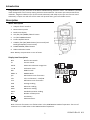
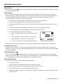
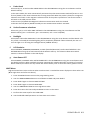
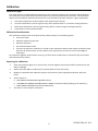
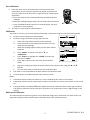
USER GUIDE Coating Thickness Tester Model CG204 Introduction Congratulations on your purchase of the Extech CG204 Coating Thickness Tester. The CG204 is a portable meter designed for non‐invasive coating thickness measurements. The meter uses two measurement methods: magnetic induction (for ferrous metal substrates) and eddy current (for non‐ferrous metal substrates). Proper use and care of this meter will provide many years of reliable service. Description Meter Description 1. USB jack for PC interface 2. Measurement probe 3. Backlit LCD display 4. SET /OK /YES /MENU /SELECT button 5. UP /LEFT ARROW button 6. Power ON/OFF button 7. CANCEL /ESC /NO /BACK button (menu mode) and Backlight ON/OFF (normal mode) 8. DOWN ARROW /RIGHT button 9. ZERO calibration button Note: Battery compartment on rear of meter Display Icon Description NFe Fe Non‐ferrous metals Ferrous metals AUTO Automatic substrate recognition F or N Calibration icons DIR DIRECT mode GRO1…4 GROUP Mode µm Micrometers unit of measure [AUT O] mils mils = millimeters * 2.54/100 Millimeters unit of measure AVG Average reading MIN Minimum reading MAX Maximum reading Standard Deviation reading NO Number of data points Low battery USB Connection H L cal n o(1 or 2) zero n o(yes) mm SDEV [NO ALRRM] 1 = = Note: The unit of measure icon flashes when in the CONTINUOUS mode of operation. The unit of measure icon is stable when in the SINGLE mode of operation. 2 CG204-EU-EN v2.2 8/13 Quick Start Instructions Meter Power Press the power button to switch the meter ON. The display will switch ON. If the display does not switch ON, replace the batteries. Measurements Use the supplied film references and zero reference metal substrates to learn how the meter operates before moving to a professional application. The round metal substrate is the ferrous (magnetic) substrate and the rectangular shaped metal substrate is the non‐ferrous (non‐magnetic) substrate. The meter automatically senses ferrous or non‐ferrous substrates. 1. Place a reference film (250µm, for example) on the round, ferrous substrate. 2. Place the spring‐loaded meter sensor against the reference film. 3. In the single mode the meter will emit an audible tone indicating that the measurement has been taken. 4. In the continuous mode the display will continually measure and update the display 5. The LCD will show the reading (250µm) at the center of the display area. 6. A typical display will also show the following: NO = 1 (reading number one) on the lower left of the LCD AVG = 250µm (running average) on the lower right DIR = DIR mode of operation on the upper left Fe = Ferrous substrate on the upper right of the LCD DIR NO=1 250 Fe um AVG=250 Experiment with the remaining reference films and the substrate before using the meter professionally. Automatic Power OFF In order to conserve battery life, the meter will automatically turn off after approximately 3 minutes. To defeat this feature use the programming menu detailed in the next section (menu parameter AUTO POWER OFF under OPTIONS). LCD Backlight Button The LCD is equipped with backlighting for easier viewing, especially in dimly lit areas. Press the backlight button to turn the backlight on. Press again to turn the backlight off. To enable/disable the LCD backlighting, use the BACKLIGHT parameter under OPTIONS in the programming menu. Factory Default Reset To restore the meter to its original factory default settings: 1. Turn the meter OFF. 2. Press and hold the ZERO button while switching the meter ON. 3. When the meter powers up, the display will prompt for a YES or NO. 4. Press the SET button for YES or the CANCEL button for NO. 5. Note that all data in all memory locations will be erased, in addition to statistics, calibration values, and alarm limits. 3 CG204-EU-EN v2.2 8/13 Programming Menu The meter can be configured and calibrated through simple button presses in the programming menu. Press the MENU button to access the menu and refer to the menu ‘tree’ below. The menu uses UP/DOWN, SELECT, BACK, & ESC presses for navigation and selection. In the table below the factory default settings are in bold with an asterisk. Each parameter is explained in detail in the subsequent sections. Top level STATISTICAL VIEW Sub level 1 Sub level 2 Notes AVG* Average of a series of readings MIN Lowest of a series of readings MAX Highest of a series of readings NO Number of sampled readings SDEV Standard deviation of a series Measure mode Working mode Probe used OPTIONS Unit settings Backlight LCD Statistics Auto Power OFF LIMIT DELETE MEASUREMENT VIEW CALIBRATION Single* One reading at a time Continuous Continuous measurements Direct* Readings are not stored in groups Group 1…4 Store readings in groups Auto* Meter automatically selects mode Fe Ferrous measurement mode No Fe Non‐ferrous measurement mode µm* Micrometers mils Mils = mm * 2.54 / 100 mm Millimeters ON* Enables backlight operation OFF Disables backlight operation AVG* Average of a series of readings MAX Lowest of a series of readings MIN Highest of a series of readings SDEV Standard deviation of a series Enable* Allows auto power off to operate Disable Defeats the auto power off feature High Limit High Alarm alerts user when reached Low Limit Low Alarm alerts user when reached Delete Limits Clear the alarm limit values Current Data Delete current data All Data Delete all stored data Group Data Delete data stored data plus alarm and calibration data Limit settings View stored data in all groups Enable Allow calibration access Disable Lock out the calibration mode Delete Zero N Clear the zero cal. data (non‐ferrous) Delete Zero F Clear the zero cal. data (ferrous) NOTE: Disable the Auto Power OFF feature before lengthy programming to avoid inconvenient automatic power down while programming. 4 CG204-EU-EN v2.2 8/13 STATISTICAL VIEWS Menu 1. Press the MENU button to access the programming menu 2. Press SELECT to choose STATISTCAL VIEW 3. Use the UP and DOWN buttons to scroll through the AVERAGE, MINIMUM, MAXIMUM, NUMBER OF DATA, and SDEV (Standard Deviation) values for the stored readings. 4. ‘NO DATA’ will display if no readings are available for the meter to analyze. Stored readings will clear when the meter powers down unless the GROUP feature is used (refer to GROUP function explanation later in this section). 5. Press the BACK and then the ESC soft‐keys to return to the normal operating mode. OPTIONS Menu 1. Press the MENU button to access the programming menu 2. Use the DOWN ARROW button to scroll down to OPTIONS 3. Press SELECT to choose OPTIONS 4. Use the UP and DOWN buttons to scroll to the MEASURE MODE, WORKING MODE, PROBE USED, UNIT SETTINGS, BACKLIGHT, LCD STATISTICS, AND AUTO POWER OFF parameters. Use the SELECT soft‐key to select the desired parameter. Each parameter is detailed below: a. Measure Modes Select CONTINUOUS or SINGLE under MEASURE MODES in the OPTIONS Menu using the arrow buttons and the SELECT soft‐key. In the CONTINUOUS measurement mode the meter displays a running average of readings as they are taken. Note that the audible measurement ‘beep’ is not active in this mode. In the SINGLE measurement mode measurements are taken one at a time. Single mode measurement readings are accompanied by an audible tone. b. Working Modes Select DIRECT or GROUP 1, 2, 3, or 4 under WORKING MODES in the OPTIONS Menu using the arrow buttons and the SELECT soft‐key. In DIRECT mode, individual readings are logged to memory. When power is switched off or if the meter is switched to GROUP mode, all DIRECT readings will be cleared. However, the statistical analysis data will remain. The statistical analysis utility can evaluate up to 80 readings. When the memory is filled, new readings will replace old readings. Lastly, this mode has its own calibration and alarm limit values. In GROUP mode each group memory can store a maximum of 80 readings and 5 statistical values. Calibration and alarm limit values can be individually set and stored for each group. When the memory is filled, measurements will continue to be taken but readings will no longer log (previously logged readings are not affected); in addition, statistical data will no longer update. If desired, the group data, statistical values, calibration data, and alarm limit values can be deleted using the programming menu. 5 CG204-EU-EN v2.2 8/13 c. Probe Used Select AUTO, Fe, or No Fe under PROBE USED in the OPTIONS Menu using the arrow buttons and the SELECT soft‐key. In the AUTO mode, the meter automatically activates the probe measurement method (ferrous or non‐ ferrous) based on the metal substrate that is being measured. When the probe is placed on a magnetic substrate it will work in the magnetic induction mode. If the probe is placed on a non‐ferrous metal it will work in the eddy current mode. In the Ferrous (Fe) Mode the Magnetic induction measurement mode is activated. In the Non‐Ferrous (No Fe) Mode the eddy current measurement mode is activated. d. Units of measure selections Select mm, µm, or mils under UNIT SETTING in the OPTIONS Menu using the arrow buttons and the SELECT soft‐key (mm = millimeters; µm = micrometers; mils = mm*2.54/100) e. Backlight Select ON or OFF under BACKLIGHT in the OPTIONS Menu using the arrow buttons and the SELECT soft‐ key. If OFF is selected the LCD backlighting will be completely disabled. If ON is selected, the user can turn the light on or off using the backlight button (CANCEL button). f. LCD Statistics Select AVERAGE, MINIMUM, MAXIMUM, or SDEV (Standard Deviation) under LCD STATISTICS in the OPTIONS Menu using the arrow buttons and the SELECT soft‐key. This selection determines which statistic is shown as default on the LCD display. g. Auto Power OFF Select ENABLE or DISABLE under AUTO POWER OFF in the OPTIONS Menu using the arrow buttons and the SELECT soft‐key. When enabled, the meter automatically switches OFF after 3 minutes of inactivity. When disabled, the meter will only switch OFF with a button press or when the battery power is weak. LIMIT Menu High and Low Alarm Limits can be set when an Alarm Limit is reached the meter displays an Alarm Alert icon (H for High Alarm and L for Low Alarm). 1. Press the MENU button to access the programming menu 2. User the DOWN ARROW button to scroll down to LIMIT and press SELECT 3. Press SELECT again to choose LIMIT SETTING 4. Press SELECT again to choose HIGH LIMIT 5. User the ARROW BUTTONS to set a High Alarm value 6. Press OK to store the limit and press BACK to return to the menu 7. Perform the same steps for the LOW LIMIT 8. Use the DELETE LIMIT parameter to clear Alarm Limit values 6 CG204-EU-EN v2.2 8/13 DELETE Menu The DELETE menus allows for deleting current data, all data, and group data. The following parameters are available in the DELETE Menu: Delete Current data: Deletes the current reading and updates the statistics (AVG, MIN, MAX, etc.) Delete All data: Delete all reading and statistical data. Delete Group data: This function duplicates the “Delete all data” function with additional, deletions of High alarm, Low alarm, and one‐ and two‐point calibrations. 1. Press the MENU button to access the programming menu. 2. User the DOWN ARROW button to scroll down to DELETE. 3. Press SELECT to open the DELETE function. 4. User the ARROW keys to scroll to CURRENT, ALL, or GROUP. 5. Press SELECT again to choose CURRENT, ALL, or GROUP. 6. The meter will prompt with an ‘are you sure?” confirmation. 7. Press YES or NO as desired. MEASUREMENT VIEW Menu The Measurement View menu allows for scrolling through the readings in all of the groups. 1. Press the MENU button to access the programming menu. 2. User the DOWN ARROW button to scroll down to MEASUREMENT VIEW. 3. Press SELECT to open the MEASUREMENT VIEW parameter. 4. User the ARROW buttons to scroll through the stored readings. CALIBRATION Menu The Calibration menu allows the user to enable/disable the calibration utility. The Calibration menu also allows the user to delete Zero calibration data for both ferrous (Zero F) and non‐ferrous (Zero N) modes. 1. Press the MENU button to access the programming menu. 2. User the DOWN ARROW button to scroll down to CALIBRATION. 3. Press SELECT to open the CALIBRATION parameter. 4. User the ARROW to scroll through the available parameters detailed below. ENABLE: Enable the calibration mode DISABLE: Disable the calibration mode. DELETE ZERO N: Delete ZERO calibration data for non‐ferrous probe DELETE ZERO F Delete ZERO calibration data for ferrous probe Measurement Considerations 1. After calibration, measurements should meet the published accuracy specifications. 2. Strong magnetic fields can affect the readings. 3. When using the statistical analysis functions for obtaining a mean value, take several readings of the same measurement area. False readings or outliers can then be removed (deleted) using the programming menu. 4. The final reading is derived from a statistical calculation with regard to the meter’s published accuracy specifications. 7 CG204-EU-EN v2.2 8/13 Calibration Calibration Types The meter is factory calibrated before shipment to the customer; however the customer should perform a zero calibration and a multi‐point calibration before any critical measurements are taken. The calibration options are listed below. Read the description for each and select the best match for a given application. 1. Zero Point Calibration: Perform before each measurement session. 2. One Point Calibration: Use for high accuracy with repeated tests on a constant coating thickness. 3. Multi‐Point Calibration: Use for high accuracy within a known range of coating thickness. 4. Calibration for shot‐blasted surfaces. Calibration Considerations The calibration sample must correspond to the product sample in the following ways: Curvature radius Substrate material properties Substrate thickness Size of measurement area The point at which the calibration is made on the calibration sample must always be identical with the point of measurement on the product itself, especially in the case of corners and edges of small parts. To achieve the highest measurement accuracy, perform several calibrations in succession (for zero values and calibration film values). Preparing for calibration 1. Clean the probe tip (grease, oil, metal scrap, and the slightest impurity will affect measurement and distort readings). 2. Switch the meter ON (at a 10cm [4”] minimum distance from any metal). 3. Ready the supplied metal substrate samples and necessary films (supplied calibration reference films). 4. Set the meter to: a. DIR: (MENU‐OPTIONS‐Working Mode‐Direct) b. CONTINUOUS: (MENU‐OPTIONS‐Measure Mode‐Continuous mode [flashing units indicator] ) c. MAX: (MENU‐OPTIONS‐LCD Statistic‐Maximum). The meter is now ready for calibration. 5. 8 CG204-EU-EN v2.2 8/13 Zero calibration 1. Place the meter on an uncoated section of the material to be measured or on the reference substrate provided. Use either the Ferrous or Non‐Ferrous reference as required by the measurement application. a. Place the probe on the uncoated substrate and watch the LCD readings. b. When the readings appear stable, lift the meter off the substrate c. Press and Hold the Zero button for 2 seconds (beep). The Zero calibration is now complete. 2. The meter is now ready for measurements Calibration The meter’s accuracy can be enhanced by performing a calibration using the reference films supplied. 1. Perform a zero calibration as stated above 2. Perform a range calibration using a reference film. a. Place one of the reference films on the substrate. b. Place the meter on the calibration reference film and watch the LCD readings. c. When the readings appear stable, lift the meter off the substrate d. Press “MENU” and then scroll down “▼” to “Calibration”. e. Press “Select” to highlight the “Enable” function and then press “Select”. f. Press “Esc” and the meter will enter the calibration mode. g. Adjust the reading to match the known value of the reference film using the ▲ and ▼ buttons. h. Turn the meter OFF to exit and save the calibration data 3. The meter is now calibrated to the base material and thickness used. 4. Perform Step 2 as needed using the other reference films. Notes: 1. Calibration data is stored into memory it is not erased when the meter is turned OFF. 2. Frequently wipe the sensor contact with a clean lint free cloth to remove any particles on the sensor tip. 3. During calibration the ▲ and ▼buttons adjust the internal calibration factors with high resolution. The display resolution may be such that it may take up to 10 presses to see a 1 digit change on the display. Multi‐point Calibration This method requires performing two or more sequential single point calibrations. For best results, the expected coating thickness measurements should be within the calibration points. 9 CG204-EU-EN v2.2 8/13 Calibrating for Shot‐blasted surfaces The physical nature of shot‐blasted surfaces results in higher than normal coating thickness readings. The mean thickness over the peaks can be determined as follows: 1. The meter should be calibrated according to the calibration instructions. Use a smooth calibration sample with the same curvature radius and the same substrate as the device to be tested. 2. Take approx. 10 readings on the uncoated, shot‐blasted sample to produce the mean value Xo. 3. Take an additional 10 readings on the coated, shot blasted test sample to produce the mean value Xm 4. The difference between the two mean values is the mean coating thickness Xeff over the peaks. The greater standard deviation ‘S’ of the two values Xm and Xo should also be taken into consideration: Xeff = (Xm ‐ Xo) ±S NOTE: For coatings thicker than 300 µm, the influence of roughness generally is of no importance and therefore it is not necessary to apply the above calibration methods. 10 CG204-EU-EN v2.2 8/13 Statistical Analysis Considerations The meter calculates statistics from a maximum of 80 readings (For Group 1 through Group 4, a maximum of 400 readings can be stored). Note that readings cannot be stored when in DIRECT mode. However, statistics on these readings can still be calculated. When the meter is powered off or if the working mode is changed (in the programming menu), the DIRECT mode statistics will be lost. The following statistical values can be calculated: NO.: Number of readings AVG: Average value Sdev. : Standard deviation (square root of a data set’s variance) MAX: Maximum reading MIN: Minimum reading Statistical Terms x ) is the sum of readings divided by the number of readings. x x/n Average value ( Standard Deviation (Sdev) The sample standard deviation is a statistic that measures how the sample value is distributed around 2 the sample mean. The standard deviation of a set of numbers is the root mean square of the variance S The variance of a list is the square of the standard deviation of the list, that is, the average of the squares of the deviations of the numbers in the list from their mean divided by the(number of readings ‐ 1 ) 2 Variance: S = 2 ( x x ) /( n 1 ) 2 Standard deviation: S= S NOTE: Use the DELETE parameter from the programming menu immediately after an outlier or erratic reading has been taken. Refer to the Delete function in Programming Menu. Storage Capacity Overflow In GROUP mode, if the storage capacity is exceeded, statistics will not be updated, although measurements can still be made. If the memory is full, subsequent readings will not be included in the statistics. The meter’s display will show “FULL” (in the SINGLE measurement mode). In DIRECT mode, when the memory is full, the newest reading will replace the oldest reading and the statistics will be updated. 11 CG204-EU-EN v2.2 8/13 PC Interface This meter has the capability to connect to and communicate with a PC. To install and use the software, please refer to the instructions provided on the supplied CD‐ROM and/or the instructions provided in the HELP Utility within the software program. Check the software download page of the website www.extech.com for the latest version of the PC software and its operating system compatibility. Error Messages The following error messages will appear on the meter’s LCD if a problem arises. Err1: Eddy current probe error Err2: Magnetic induction probe error Err3: Eddy current and Magnetic induction errors Err4, 5, 6: Unused error displays Err7: Thickness error Please contact Extech Instruments if a problem exists. Maintenance Cleaning and Storage Periodically wipe the meter housing with a damp cloth and mild detergent; do not use abra‐sives or solvents. If the meter is not to be used for 60 days or more, remove the batteries and store them separately. Battery Replacement/Installation instructions 1. Remove the Phillips head screw that secures the rear battery door 2. Open the battery compartment 3. Replace/install the two 1.5V ‘AAA’ batteries 4. Secure the battery compartment You, as the end user, are legally bound (Battery ordinance) to return all used batteries and accumulators; disposal in the household garbage is prohibited! You can hand over your used batteries / accumulators at collection points in your community or wherever batteries / accumulators are sold! Disposal: Follow the valid legal stipulations in respect of the disposal of the device at the end of its lifecycle 12 CG204-EU-EN v2.2 8/13 Specifications Sensor probe Ferrous Non‐Ferrous Measurement principle Magnetic induction Eddy current principle Measuring range 0~1250μm 0~1250μm 0~49.21mils 0~49.21mils Accuracy 0~850μm: ±(3% + 1μm) 0~850μm: ±(3% + 1.5μm) (% of reading) 850μm ~1250μm: (±5%) 850μm ~1250μm: (±5%) 0~33.46mils: ±(3% + 0.039mils) 0~33.46mils: ±(3% + 0.059mils) 33.46mils ~49.21mils: (±5%) 33.46mils ~49.21mils: (±5%) 0~50μm: (0.1μm) 0~50μm: (0.1μm) 50μm ~850μm: (1μm) 50μm ~850μm: (1μm) 850μm ~1250μm: (0.01μm) 850μm ~1250μm: (0.01μm) 0~1.968mils: (0.001mils) 0~1.968mils: (0.001mils) 1 Resolution 1.968mils~33.46mil:s (0.01mils) 1.968mils~33.46mils: (0.01mils) 33.46mils~49.21mils: (0.1mils) 33.46mils~49.21mils: (0.1mils) Min. curvature radius 1.5mm 3mm Diameter of Min. area 7mm 5mm Basic critical thickness 0.5mm 0.3mm Industrial standards Conforms to GB/T 4956‐1985, GB/T 4957‐1985, JB/T 8393‐1996, JJG 889‐ 95, and JJG 818‐93 Operating Temperature 32°F~104°F (0°C~40°C) Operating Relative Humidity (R.H.) 20%~90% Relative Humidity Dimensions 4.3 x 2.0 x 1.0” (110 x 50 x 23mm) Weight 3.9 oz. (100g) Accuracy statement applies on a flat surface, with a zero and a calibration performed near the thickness of the film to be measured, with an identical base metal and with the meter stabilized at ambient temperature. The accuracy of the reference films or any reference standards should be added to measurement results. Copyright © 2013 FLIR Systems, Inc. All rights reserved including the right of reproduction in whole or in part in any form www.extech.com 13 CG204-EU-EN v2.2 8/13