1
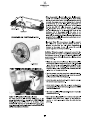
HYDROPOOL
swim spa
owner’s manual
Hydropool Inc.:
99399
Tel: 905.565.6810
Toll Free: 1.800.465.2933
Fax: 905.565.6820
Email: [email protected]
www.hydropoolhottubs.com
BJAA
TABLE OF CONTENTS
Letter of Introduction ...................................................................3
Diagnostic Messages ................................................................27
Important User Safety instructions
Warnings ...............................................................................4
Hyperthermia ........................................................................4
Topside Control Panel Display Messages ..............................28
Jet and Feature Operation
Jet Water Flow Adjustment ...............................................30
Jet Air Flow Adjustment ....................................................30
Jet Insert Removal & Replacement ..................................30
Interchanging Jet Inserts ..................................................30
Cleaning Stainless Steel Jets and Controls ....................30
Adjustable Flow Control (Diverter) Valves ...................... 31
Self-Cleaning Mode Cabinet Light............. ...................... 31
Choosing the Right Location
Indoor Locations...................................................................5
Outdoor Locations ................................................................5
General Installation Considerations ..........................................6
Special Considerations
Indoor Installations ..............................................................6
Outdoor Installations ...........................................................6
Swim Spa Water Balance
General Overview ...............................................................32
Initial Fill ........................................................................... 32
Glossary of Common Water Maintenance Terms ............33
Water Balance Summary Chart ........................................33
Water Balance Troubleshooting .......................................34
Corona Discharge Ozone Technology ..............................35
Site Preparation
Above Ground Installations .................................................7
In-ground & Partial In-ground Installations ......................7
Equipment Accessibility & Protection ...............................8
Remote Equipment
Remote Equipment Placement ............................................9
Above-Grade Equipment Placement ..................................9
Remote Equipment Plumbing Diagrams .............................9
Routine Swim Spa Maintenance
Daily, Weekly, Monthly, Annually .....................................35
Cleaning the Skimmer Basket ...........................................35
Cartridge Filter - Removal, Cleaning, Re-Installation .....36
Cleaning the Acrylic Surface ............................................36
Safety Hard Cover ..............................................................36
Changing Your Swim Spa Water .......................................37
Draining Your Swim Spa Water.........................................37
Water Softeners .................................................................37
Unloading/Handling Your Swim Spa .......................................10
Leveling Your Hydropool Swim Spa ........................................11
Set-up and Assembly
Steel Support Leg Assembly – Overview .........................11
Steel Support Leg Assembly – Details .............................12
Support Equipment Assembly ...........................................13
Ozonator Connection .........................................................13
LED Light Assembly ............................................................14
TopSide Control Panel Connection ...................................14
Cabinet
Protecting Your Cabinet Wood Finish ...............................38
Cabinet Wing-Locks ...........................................................38
Important Electrical Safety Instructions
GFCI / RCD Application Guide & Wire Size......................14
North America – GFCI installation ....................................15
Europe – R.C.D. installation ...............................................16
Winterizing Your Swim Spa ......................................................39
General Troubleshooting ...........................................................40
What to do in the event of
Power fluctuations. ............................................................41
Cold weather power failure ..............................................41
Swim Jets Pump(s) Timer – Europe Only ................................17
Accessories
Corner Wrap Pillow ............................................................18
AquaCord Tether System/ Rowing kit ...............................18
Filter Cover ..........................................................................18
Waterfall Pillows (FX model only)..................................... 18
Your Dream Scents Aromatherapy System...................... 18
Safety Hard Cover Locks ...................................................19
LED Mood Lighting .............................................................19
Rowing Kit ..........................................................................19
Cover Remover – Optional ................................................19
Everlast four-tier steps .....................................................19
Filling, Checking and Starting Your Swim Spa ......................20
Pump Priming/Releasing an Air Lock ...............................21
Hydropool Control Systems
North America and Europe
AquaTrainer and AquaSport Series ..................................22
AquaSport Series ...............................................................26
2
SITE PREPARATION
ABOVE-GROUND INSTALLATIONS
Recommended Minimum Concrete Pad Dimensions
Where the swim spa is a ”stand-alone“ above-ground
installation to be installed in regions where freeze/thaw
conditions may occur, a level patio stone or
pre-formed paver type base may be sufficient if there is no
abutting deck(s) that could be damaged during potential
seasonal movement of the ground. The potential drawback
to this type of base is that splash water could eventually
de-stabilize the ground under the base, with the resultant
shift of the support base causing damage to the swim spa
structure.
With Factory
Cabinet & Steps
Without Cabinet
14 ft. Model
259 cm x 576 cm
102 in x 228 in
239 cm x 488 cm
94 in x 192 in
17 ft. Model
259 cm x 671 cm
102 in x 264 in
239 cm x 576 cm
94 in x 228 in
19 ft. Model
259 cm x 711 cm
102 in x 280 in
239 cm x 620 cm
94 in x 244 in
In regions where freeze/thaw occurs, or where there will be
custom decking abutting the swim spa, we recommend
the installation of poured concrete footings extending
below the frost line beneath the pad to prevent the
possibility of future shifting.
For best results, we recommend the installation of a LEVEL
concrete pad:
• Dig out and level the ground 20-30 cm (8-12 in.) below
your desired base level
• Install 10-15 cm (4-6 in.) of crushed stone
• Next, install 10-15 cm (4-6 in.) of poured concrete
• Level the concrete and apply a broom-type finish
INSTALLATION EXAMPLES
WOOD OR
CONCRETE DECK
FACTORY INSTALLED
PLUMBING
WOOD OR
CONCRETE DECK
FACTORY INSTALLED
PLUMBING
STEEL SUPPORTS
OPEN
CAVITY
(minimum requirement)
(minimum requirement)
6" GRAVEL
STEEL SUPPORTS
POURED 4" SLAB
POURED 4" SLAB
NATURAL DRAIN
NATURAL DRAIN
POURED
CONCRETE
FOOTINGS
6" GRAVEL
IN-GROUND & PARTIAL IN-GROUND INSTALLATIONS
• When recessing the swim spa all or part way below
ground level, a concrete base along with a concrete or wood
retaining wall to hold back the earth is suggested.
This forms a box or ’bunker‘, in which the swim spa
is placed. Hydropool does not recommend back-filling
full in-ground or partial in-ground installations without
the backfillable frame accessory.
• It is recommended leaving a 61 cm (24 in) wide
crawl-space around the entire unit to ensure adequate
accessibility.
• ALWAYS ensure that there is good drainage, via a
properly designed French (gravel) drain system and/or a
sump pump, to prevent ground water flooding damage to
the support equipment or structure swim spa
• Install protective waterproof conduit to house light, or
topside control cables that will be buried
• Access for future service must be considered at the time
of design and installation. Difficult access can result
in supplemental service labour charges not covered by
the factory warranty. Consider easily removable deck
materials.
Bunker – Recommended Minimum Interior Dimensions
14 ft.
AT/AS
17 ft.
AT/AS
14 ft. IX
AT/AS
19 ft. FX
AT/AS
174 in x 93 in
442 cm x 236 cm
210 in x 93 in
533 cm x 236 cm
168 in x 93 in
427 cm x 236 cm
220 in x 93 in
559 cm x 236 cm
7
REMOTE EQUIPMENT
REMOTE EQUIPMENT PLACEMENT
remote plumbing lines be buried below the frost line and
that pipe insulation is applied over all pipes that run from
the swim spa to the remote equipment to help maintain
energy efficiency.
• The swim spa equipment is designed for indoor/out
of the direct elements use. Your custom enclosure
or other structure must be designed to provide
protection for the swim spa support equipment from
rain, snow, splash water, etc., but still designed in a
manner to ensure adequate ventilation.
• All field installed plumbing must meet minimum sizes
as previously outlined in order to conform to regulated
standards regarding safe inlet and outlet flows. If required,
please call your dealer for more detailed drawings.
• The equipment should be located as close to the swim
spa as possible to maximize jet performance
• Whenever possible, install the pump(s) and control
with heater below water level to ensure easy priming
• The distance of the swim spa support equipment from
the unit should never exceed 3m (10 ft.) of pipe length,
otherwise jet performance will be affected.
• Piping diameter on pump lines must be 2.5 in. for inlet/
suction pipes and 2 in. for outlet/pressure pipes with
minimal use of elbows.
• Install protective waterproof conduit to house
applicable cords or line extensions such as the topside
control cables, light wires or ozone tubing.
• In climates where freeze/thaw occurs we recommend that
REMOTE EQUIPMENT PLUMBING DIAGRAMS
Outlet/Pressure Side Plumbing Connections
Inlet/Suction Side Plumbing Connections
D
P3
Pump 1
F
PACK
P1
Pump 1
P2
P1
2 1/2" Dia.
2" Dia.
Pump 2 & 3
P3
Pump 2 & 3
P1
P2
2" Dia.
9
SUPPORT EQUIPMENT ASSEMBLY
o-rings are properly seated and do not get pinched while
connecting the unions as this will result in leaks. Union
connections are located on the swim spa control heater
manifold, pipe to pipe connections and all pumps.
Position equipment platform next to the swim spa under
the swim jets. Do not remove support equipment from
platform. All necessary o-rings are bundled and shipped
in the accessories bag. Carefully install o-rings into
unions and hand tighten all connections. Ensure that
AQUATRAINER SUPPORT EQUIPMENT PLATFORM – TYPICAL (EUROPEAN VERSION SHOWN)
AQUASPORT SUPPORT EQUIPMENT PLATFORM – TYPICAL
(NORTH AMERICAN VERSION SHOWN)
Equipment may not be exactly as shown.
OZONATOR CONNECTION
The clear 9.5 mm (3/8 in) ID ozonator tube is
shipped coiled and attached to the back of the
swim jets. Attach loose end to barb on ozonator,
and ensure that the ozone check valve is oriented
vertically.
13
ACCESSORIES
When unpacking your new Hydropool swim spa, you will find an accessories bag inside containing:
• all necessary o-rings/gaskets
• gate valve stem locks
• filter cover
• #10 expansion plug (for skimmer when draining)
• Aquacord swim tether (Aquatrainer & Aquasport only)
• chrome decorative lip trim
CORNER WRAP PILLOW
The corner wrap pillows are pre-installed at the factory and are
attached via pins. To remove, grasp ends of pillow and pull out
from hot tub seat. To re-install, reverse procedure.
Although the pillows are designed to remain in-place in the swim spa, to extend the life of the pillows, remove after each use.
AQUACORD TETHER SYSTEM
around your waste. Adjust the Aquacord length so
that your extended arm has at least 46 cm (18 in.) of clearance from the end of the swim spa.
Sould you desire a tether resistance swim or excercise,
simply lift the cap of the Aquacord tether anchor and slip
one end of the Aquacord onto the anchor and the other
FILTER COVER
The filter cover provides that finishing
touch to your Hydropool swim spa.
To install simply place over the filter
opening.
WATERFALL PILLOWS (FX model only)
If you received the optional waterfall package, remove the blade from the waterfall receiver fitting in the hot tub (already
installed at the factory). Insert the waterfall blade through the front of the special waterfall pillow. The front flange of
the waterfall blade will be recessed into the front of the pillow. If it is not recessed, the blade needs to be removed and
re-inserted through the opposite side of the pillow. Push the pillow into the semi-circular recess, ensuring that the portion
of the blade protruding out of the back of the pillow inserts firmly into the waterfall receiver fitting.
18
YOUR DREAM SCENTS AROMATHERAPY SYSTEM
Operational Instructions:
This exclusive aromatherapy system is independent from the blower and uses liquid
scents.
To operate the system is very simple:
1) To Refill begin by opening the cap “counterclockwise” on the unit and remove.
There are arrows on the cap to indicate the direction in which to turn the cap to
open. Then fill the reservoir with your favorite Hydropool liquid scent (or equivalent).
To replace cap perform the reverse of the above directions.
2) Now the system is ready to work: just push the button to release the scent into the
hot tub and repeat to add more liquid scent as desired, please note by turning the
button clockwise you can lock it so that any accidental pushing of the button will
not result in adding unwanted liquid scent when not desired.
To unlock turn button counter-clockwise.
COVER REMOVER - OPTIONAL
WARNING
A Hydropool cover lifter assists in the removal of the safety
hard cover. Please refer to the instructions supplied with
your particular cover remover for installation. For further information, contact your local Hydropool retailer.
Always ensure the safety hard cover is
in place and locked whenever the hot tub
is not being used.
ROWING KIT
LED MOOD LIGHTING
The Aquatic Rowing Kit
is a combination of stainless
steel oars and resistant
tether cords that attach to
a swivel anchors allowing
a full rowing motion.
Press the ‘light’ pad on the topside control to start the
following LED lighting modes. Pressing the ‘light’ pad on/off
within 3 seconds cycles through the various ‘light shows’.
When the LED lighting is turned off for more than 5 seconds, then turned back on, the system will resume the last
‘light show’.
Description of Light Shows:
• Mode 1 – Synchronous colour change
• Mode 2 – Freeze mode, freezes on selected colour blend
from above mode (gives unlimited colour blend selection)
• Mode 3 – solid colour blue
• Mode 4 – solid colour green
• Mode 5 – solid colour red
• Mode 6 – solid white (simulated)
SWIM STEPS
To assist in the entry and exit
of the swim spa Hydropool
offers either a matching
three tier Natural Western
Red Cedar (pictured in inset
above) or a four tier Universal
Step in either matching
Espresso or Driftwood color
with black railings.
SAFETY HARDCOVER LOCKS
In an uncovered swim spa, over 90% of the heat is lost from
the water surface. Hydropool hard covers are engineered
for maximum thermal efficiency and appearance. Simply
place the cover on the swim spa, pull the straps down so
that they are fully extended, then release slightly so that
there is approximately 6 mm (1/4 in.) of slack. Mark the position on the cabinet or deck surface, and fasten the receiver
clip with the screws provided.
19
HYDROPOOL SWIM SPA SERIES CONTROL SYSTEMS
NORTH AMERICA AND EUROPE
HYDROPOOL AQUATRAINER
PUMP PRIMING MODE
As soon as PRIMING MODE is indicated
on the topside panel, push the left
pad
to start Pump 1 in low speed, then again
to switch to high speed. Push the
center
pad and right
pad to start
Flashing Pump 2 and *Pump 3 respectively
Pump Icon(s)
(*Titanium Series only). These are both
single speed - high only. All of the pumps
will now be operating in high speed to facilitate priming.
See FILLING, CHECKING AND STARTING YOUR HOT TUB for
complete instructions on pump priming.
Once pump priming has been successfully completed,
pads to turn off the pumps. Next, manually
press the
exit PRIMING MODE by pressing either the
pad or the
pad. If you do not manually exit Priming Mode, it will
automatically terminate after 4 to 5 minutes. Be sure that
the pumps have been primed before exiting this mode.
INITIAL START-UP
Before applying voltage to power-up your hot tub, it is very
important that you understand the sequence of events that
occur when the system is activated in order that the pumps
can be primed efficiently and damage to the pumps can be
avoided.
TEMPERATURE CONTROL
FUNCTIONALITY AND ADJUSTMENT
After you manually exit or the system automatically exits
PRIMING MODE, your hot tub will automatically heat to
the factory preset default temperature of 38˚C (100˚F). The
topside panel will briefly show the default temperature, and
then the display will appear as follows:
Note that the water temperature is not
yet displayed, as the system requires
approximately 2 minutes of water flow
through the heater to determine
temperature. This is referred to as ‘polling’
and is indicated on the display by the
Flashing
Pump 1 Low speed Icon
icon. After 2 minutes the display
will show the current measured water
temperature.
At initial power-up, this display will appear,
and the system will show 4 sets of
numbers in succession (ie. 100 then 114
then 28 then 240). These numbers
represent the current software revision,
and the system input voltage.
After the initial software indicators are
shown, this display will appear. This display
is indicating that the system is in PUMP
PRIMING MODE. This mode will last for
4 to 5 minutes before automatically
Flashing
exiting and entering the normal
operation mode. You can also manually exit the PUMP
PRIMING MODE after the pumps are primed.
Press the
pad to increase the
temperature to the desired setting. The
icon will appear on the display
indicating that the heater has been
activated.
While in this mode, the heater circuit is disabled to
allow the priming process to be completed without
the possibility of energizing the heater element during
low flow or no flow conditions. The system will not
automatically activate any of the functions, however, by
pads on the topside control, the pumps
pushing the
can be manually activated to facilitate priming.
Flashing
Pump 1 Low speed Icon
In Standard Operating Mode, the system automatically
activates Pump 1 low speed every 30 minutes
for at least 2 minutes. After 2 minutes, the spa water
temperature is determined. At this point, if the water
temperature is lower than the set temperature, P1 will
icon will appear on the
continue to run and the
display. The heater will operate until the water temperature
reaches the set temperature point, after which, both the
heater and Pump 1 low will automatically turn off.
Definition: ‘Priming’ a pump is a term used to describe the
process in which air trapped in the plumbing and pump
wet-end (referred to as an ‘air lock‘) is released, allowing
the pump to move water efficiently through the plumbing
system and to the jets.
22
If the system is heating when Standby Mode is activated,
will flash on the display and the pump will continue to operate for
15 seconds to allow the heater to cool off before stopping.
All functions will turn off, but P1 low speed can be
activated (by pressing the P1
pad) to facilitate draining
or
the hot tub and the display will show
LIQUID CRYSTAL DISPLAY (LCD)
Continually provides feedback on the operating status of the hot tub.
Icons indicate various functions and programming information.
LCD INVERT
This feature inverts the LCD readout for convenient viewing from inside
the hot tub. To invert the readout,
Platinum Series: press
or
then
Titanium Series: press
To return the LCD readout to normal viewing (from outside of the hot
tub), repeat.
Press any pad other than the P1
pad to return the system to
normal operation. See section DRAINING YOUR HOT TUB for detailed
instructions.
LED MOOD LIGHTING
Press the
pad on the topside control to start the
selection of LED lighting modes. Pressing the
pad
on/off within 3 seconds cycles through the various ‘light
shows’. When the LED lighting is turned off for more than 5
seconds, then turned back on, the system will resume the last ‘light
show’. The system will automatically turn off the mood lighting after
4 hours.
OZONATOR OPTIONAL
The ozonator operates during FILTER CYCLES and CLEAN UP CYCLES
only. The display will show the O3 icon while the ozonator is operating.
Pressing any pad on the topside control panel will suspend ozonator
function for 1 hour.
FREEZE PROTECTION
If the temperature sensor detects a drop to 4˚C (39˚F)
within the heater chamber, the system automatically activates
the pumps to provide freeze protection. The pumps will
operate until the temperature reaches 5˚C (41˚F) before returning to
normal system mode.
VARIABLE AIR THERAPY SYSTEM (VATS) - Factory installed
Press this pad to turn the (VATS) on and off. The system will
automatically turn off the blower after 15 minutes.
TOPSIDE PANEL LOCK FEATURES
TEMPERATURE LOCK
The temperature lock feature prevents unauthorized
temperature adjustment of the hot tub water. When the temperature
lock is activated, all automatic functions will continue to operate
normally.
The following pads must be pressed within 3 seconds of each other to
activate the lock:
then
then P1
then
TEMPERATURE UNLOCK
The following pads must be pressed within 3 seconds of each other to
deactivate the lock:
then
then P1
then
When locked, the TL (Temperature Lock) light on the left side of the
topside control panel will illuminate. Only the topside control panel
temperature pads will be deactivated.
TOPSIDE PANEL FULL LOCK
The topside panel lock feature prevents unauthorized use of the hot
tub controls. When the topside control panel lock is activated, all
automatic functions will continue to operate normally.
The following pads must be pressed within 3 seconds of each other to
activate the lock:
then P1
then
1
2
3
TOPSIDE PANEL UNLOCK
The following pads must be pressed within 3 seconds of each other
to deactivate the lock:
then P1
then
VARIABLE SPEED BLOWER CONTROL FUNCTIONS:
When locked, the PL light (Panel Lock) on the left side
of the topside control panel will illuminate. All of the topside
control panel pads will be deactivated except for the
pad.
1) ON/OFF :
Press 1: The Blower starts at maximum Speed. LED: ON
Press 2: The blower stops. LED: OFF
STANDBY / DRAIN ASSIST
2) TO CONTROL SPEED:
The standby/drain assist feature stops the system from
operating automatically, allowing for convenient filter cartridge
removal and for safe draining of the hot tub. The following pads
must be pressed within 3 seconds of each other.
The system will automatically exit Standy Mode after 1 hour and
resume normal operating functions.
Press
then the P2
pad and the display will flash:
or
Press 1 and hold: Speed goes up or down, LED: ON when
pressing. Release pressure at the desired speed.
3) TO CONTROL PULSATION:
Press 1: Slow Pulsation Cycle, LED: ON.
Press 2: Quick Pulsation Cycle, LED: Flashes.
Press 3: Pulsation Cycle OFF, LED: OFF.
25
JET AND FEATURE OPERATION
Cluster Storm
Directional Jet
Poly Storm
Acupressure Jet
Cluster Storm
Pulsator Jet
Cluster Storm
Rifle Jet
Poly Storm
Multi massage Jet
Mini Storm
Galaxy Jet
Poly Storm
Rifle Jet
Mini Storm
Massage Jet
Power Storm
Resonator Jet
Monsoon Jet
Mini Storm
Multi Massage Jet
Power Storm
Rifle Jet
Mini Storm
Directional Jet
Power Storm
Twin Roto Jet
Patented Wide Stream Jet
JET WATER FLOW ADJUSTMENT
jet internal from the socket. All Hydropool swim spas are
shipped from the factory with the jets in the open position.
Your Hydropool swim spa features adjustable water flow on
specific hydrotherapy jets.
To reduce the flow: grasp the outer flange of the jet, and turn
clockwise approximately a 1/4 turn. When it hits the stop,
the jet is considered closed, and flow will be restricted.
To increase the flow: from the closed position, turn the jet
counter-clockwise approximately 1/4 turn. When it hits the
stop, the jet is open, and there is maximum jet flow. Do not
attempt to turn the jet past the stop, as this will unclip the
INTERCHANGING JET INSERTS
A great feature for custom tailoring the jets in your
Hydropool swim spa to suit your personal hydrotherapy
needs. Jets of like size and dimension may be interchanged
with each other, for example, if you wished to swap a
Poly Storm Directional jet for a Poly Storm Twin Roto jet, or
a Mini Storm Twin Roto jet for a Mini Storm Directional jet.
JET AIR FLOW ADJUSTMENT
JET INSERT REMOVAL & REPLACEMENT
Your Hydropool swim spa features adjustable air flow on specific
hydrotherapy jets. To reduce the flow: turn the handle on the air
control clockwise. When it hits the stop, the air is closed, and
air flow will be restricted.
To increase the flow: turn the handle on the air control
counter-clockwise. When it hits the stop, the air control is fully
opened. For maximum operating efficiency, the air controls
must remain closed when your swim spa is not in use.
POLY/MINI STORM DIRECTIONAL & TWIN ROTO
POWER STORM MASSAGE & STORM CLUSTER
TO REMOVE:
• Turn the jet counter-clockwise to unclip & pull out of socket.
TO RE-INSTALL:
• Push the jet into the socket until it snaps into place, ensuring the square pin on the back of the jet lines-up with
the groove in the socket flange. Rotate jet right or left to
ensure it is properly seated.
CLEANING STAINLESS STEEL
JETS & CONTROLS:
Use a Cleaner such as Brasso or Stainless Steel Cleaner to bring back
the lustre to your Stainless Steel parts at each refill cycle.
30