1
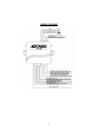
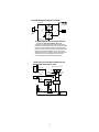
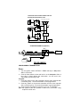
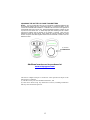
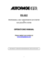
RF-350
PROFESSIONAL VEHICLE SECURITY SYSTEM
WITH KEYLESS ENTRY
INSTALLATION & USERS MANUAL
(For Authorized Dealers Only)
Please register your product at www.autopageusa.com
THIS PRODUCT IS DESIGNED FOR PROFESSIONAL INSTALLATION ONLY
1
WIRING DIAGRAM
2
H1: MAIN 5 PIN WIRE HARNESS:
1. Red / White Wire: Parking Light Relay input
2. White Wire: Parking Light Relay Output
3. Black Wire: Ground to Vehicle FRAME
4. Brown Wire: Positive output To
Siren
15A Fuse
5. Red Wire: +12V To Constant Battery Source
H2: 8 PIN MINI CONNECTOR WIRE HARNESS:
1. BROWN/WHITE...(-) HORN OUTPUT
(RELAY REQUIRED)
2. WHITE...DOME LIGHT / 3RD CHANNEL OUTPUT
3. VIOLET ...POSITIVE DOOR TRIGGER (+) INPUT
*
4. BLUE...NEGATIVE INSTANT (-) INPUT
5. GREEN...NEGATIVE DOOR TRIGGER (-) INPUT
6. YELLOW...IGNITION INPUT
7. ORANGE...STARTER INTERUPT OUTPUT(RELAY REQUIRED)
8. GRAY ...2ND CHANNEL OUTPUT
Siren and Starter Kill relay optional
DOOR LOCK DIAGRAMS
5-WIRE ALTERNATING DOOR LOCK
+12V
Green Wire
Master Door
Lock Switch
Splice
86
3 Pin Plug
To Alarm
87
87a
Cut the Existing
Unlock Wire
30
85
X
Splice
+12V
86
87
87a
X
30
85
Blue Wire
To Slave Door
Lock switches
3
Cut the Existing
Lock Wire
To Door
Lock
Motor
VACUUM OPERATED CENTRAL LOCKING
Green Wire
86
87
87a
Door Switch
X Cut
30
85
3 Pin
Plug To
Alarm
+12V
86
87
Compressor
87a 30
85
Blue Wire
VACUUM OPERATED DOOR LOCKING SYSTEM:
TYPICAL OF MERCEDES BENZ AND AUDI.
Locate the wire under the driver's kick panel. Use the
voltmeter connecting to ground, verify that you have the
correct wire with the doors unlocked, the voltmeter will
receive "12 volts". Lock the doors and the voltmeter will
read "0 volt". Move the alligator clip to +12V and the
voltmeter will receive "12 volts". Cut this wire and make
connections. Be sure to program door lock timer to
3.5 seconds.(See Feature II – 3 Programming.)
2 STEP DOOR UNLOCK WIRE CONNECTION FOR
GROUND SWITCHED DOOR LOCKS
8-Pin
Plug
From
Alarm
OEM Door Master Lock Switch
H2/8 Gray Wire
Unlock
Lock
Existing Neg.
3 Pin Plug
To Alarm
H3/3 Green
Wire
Door Lock
H3/1 Blue
Wire
Door Unlock
Existing Neg.
Lock Wire
Unlock Wire
87
85
86
OEM Door
Lock Relay
87A
30
+ 12V
OEM
Door Lock
Motor
X
Cut Existing Unlock
4
To All Other
Door Lock
Motors
2 STEP DOOR UNLOCK WIRE CONNECTION FOR
POSITIVE SWITCHED DOOR LOCKS
+12V
8-Pin
Plug
From
Alarm
OEM Door Master Lock Switch
H2/8
Gray Wire
87
Unlock
86
87A
Existing Pos.
Unlock Wire
30
H3/3 Green Wire
Door Lock
Lock
85
+ 12V
Existing Pos.
Lock Wire
87
87A
+ 12V
85
86
30
H3/1 Blue
Wire
Door Unlock
+ 12V
OEM Door
Lock Relay
87
87A
85
86
OEM Driver's
Door Lock
Motor
30
X
To All Other
Door Lock
Motors
Cut Existing Unlock
STARTER DISABLE ( Optional )
RK-1
87
<12V (+) Ignition>
<White Wire>
<Red>
87a
<Starter Wire (key side)>
<Yellow>
85
30
Orange
Starter Disable
Wire
86
<Starter Wire (motor side)>
<Purple>
STARTER
PROGRAMMING
PROGRAMMING TRANSMITTERS:
Enter:
1.
Turn the Ignition 'switch ‘OFF/ON’ 3 TIMES and stay in ON position.
Within 15 seconds,
2. Push the Valet switch 2 times and hold in on the 2nd push. When a
long chirp is heard release the valet switch. You are now in the
Transmitter programming mode.
Program:
1. Press any button on the first transmitter until the siren responds with
a confirming chirp. The first transmitter is now programmed.
2. Press any button on the second transmitter until the siren responds
with a confirming chirp. The second transmitter is now programmed.
th
3. Apply the same procedure to program any 3rd or 4 transmitter.
Exit: Turn Ignition to the 'OFF' position, or leave it for 15 seconds. 3 long
chirps will confirm exit.
5
Note: If more than 4 transmitters are programmed, the system will only
keep the last 4 transmitters and delete the others.
ALARM FEATURE “A” PROGRAMMING:
1. Turn the Ignition 'switch ‘ON/OFF’ 3 TIMES and stay in OFF position.
rd
2. Push the Valet switch 3 times and hold in on the 3 push. When a long
chirp is heard, release the valet switch. You are now in the Alarm
feature ‘I’ programming mode.
3. Press the transmitter button corresponding to the feature you want to
program.
a. The factory default settings is always [1] LED flash, [1] chirp.
4. Depress the transmitter button again to change the feature. Simply
keep pressing the transmitter button again until the module advances
to your desired setting.
Exit: Turn Ignition to 'ON' position, or leave it for 15 seconds. 3 long
chirps will confirm exit.
Press
Transmitter
Button
One Chirp /
LED one pulse
Factory Default
Setting
1
Active arming
2
Two Chirps /
LED two pulses
Passive arming
without passive
door locking
Automatic Rearm off
Automatic Rearm
on
3
Instant Door Ajar error
chirp
45 seconds delay
Door Ajar error
chirp.
4
Siren Confirmation
chirp on only
All Confirmation
chirps On
5
+
H2/2 White wire=
Dome Light Output
H2/2 White wire=
3rd Channel
Momentary
6
+
Lock/Arm &
Unlock/Disarm
Confirmation Chirps
Lock/Arm
Confirmation
Chirp Only
7.
+
ALARM with
Keyless Entry
Keyless Entry
ONLY
8.
+
Car Jacking feature
Off
Car Jacking
feature On
6
Three Chirps
/
LED three
pulses
Passive
arming with
passive door
locking.
Horn
Confirmation
chirp on only
H2/2 White =
3rd channel
Latched
Four Chirps /
LED four
pulses
All
Confirmation
chirps off
ALARM FEATURE “B” PROGRAMMING:
1
2
3
Turn the Ignition 'switch ‘ON/OFF’ 3 TIMES and stay in OFF position.
th
Push the Valet switch 5 times and hold in on the 5 push. When a
long chirp is heard, release the valet switch. You are now in the
Alarm feature ‘B’ programming mode.
Press the transmitter button corresponding to the feature you want to
program.
Press
Transmitter
Button
One Chirp / LED
one pulse
Factory Default
Setting
Pathway
illumination
feature “off”
Two Chirps /
LED two pulses
2
Ignition
controlled door
locks & unlocks
Ignition
controlled door
locks only
Parking light
turns “on” for
30- second
upon an unlock
signal & 10second upon a
lock signal.
Ignition
controlled door
unlocks only
3
0.8-second Door
lock pulses.
3.5-second
Door lock pulse.
Double pulse
unlock
4
2 Channel
Pulsed
1
5
nd
+
Button =
Parking light
turns “on” for
30- second
upon an unlock
signal
Three Chirps /
LED three
pulses
Four Chirps /
LED four pulses
Without ignition
controlled door
locks & unlocks
Comfort feature
nd
2 Channel
Momentary
Button = 3rd
Channel Aux.
6
+
Silent Arm/Disarm
H2/8 Gray Wire =
Trunk (Channel 2)
Output
7.
+
Horn chirp
Duration
Horn chirp
Duration
Horn chirp
Duration
Horn chirp
duration
Standard
50 mS
30 mS
10 mS
H2/8 Gray Wire =
Two Step Door
Unlock Output
Exit: Turn Ignition to 'ON' position, or leave it for 15 seconds. 3 long chirps will confirm exit.
7
ALARM FEATURE “C” PROGRAMMING:
1. Turn the Ignition 'switch ‘ON/OFF’ 3 TIMES and stay in OFF position.
th
2. Push the Valet switch 7 times and hold on the 7 push until Three
chirps with a long chirp is heard then release the valet switch. You are
now in the Alarm feature ‘C’ programming mode.
3. Press and hold the transmitter
button for two seconds to enter
shock sensor program mode.
Press
Transmitter
One Chirp /
LED one pulse
Button
1
Factory Default Setting
Two Chirps /
LED two pulse
Shock Sensor Program Mode
ADJUST AND TEST THE SENSITIVITY LEVEL OF THE SHOCK
SENSOR
1. Turn the Ignition switch ‘ON/OFF’ 3 TIMES and stay in OFF position.
2. Push the Valet switch7 times holding in on the7th push. Three chirps
with a long chirp will be heard. Release the valet switch. You are now
in the Alarm feature ‘Shock Sensor’ programming mode.
3. Press and hold
button for 2 seconds. One long siren chirp will
indicate the unit is ready to accept adjustments of the shock sensor.
4. Press
button on the transmitter once. This will decrease sensitivity
level by one. Each time the button is pushed and a decrease is made
the siren/horn chirp will respond with [1] chirp. Two chirps indicate the
minimum sensitivity. Warn away & full trigger will be deleted when
minimum sensitivity is selected. Shock sensor OFF
5. Press
button on the transmitter once. This will increase sensitivity
level by one. Each time an increase is made the siren/horn chirp will
respond with [1] chirp. Two chirps indicate the maximum sensitivity.
6. Hit the bumper or strong metal part of the vehicle to test the threshold
level of the sensor.
a). Activate the warn-away (first stage the shock sensor), the siren will
emit a short chirp.
b). Activate the full alarm (second stage the shock sensor), the siren
will emit a long chirp.
7. When you are satisfied with the setting, press the
button to lock in
the adjustment. One long siren chirp will indicate the unit has locked in
the adjustment.
Note: If 30 seconds of inactivity expires or you turn ON the ignition during
of above steps, the unit will exit the program mode and return to the
disarmed mode. Three long chirps will confirm exit.
8
Operation Manual
TRANSMITTER OPERATION:
Transmitter
Button
System Function
Remark
Lock Doors & Arm System
Panic function
Press and Hold for 3 seconds
Car Locator
Under armed mode
+
Arm and Delete The 2 Stage Shock
Sensor
Silent Arming / Disarming
-
Unlock Doors & Disarm System
Two Steps Door Unlock & Disarm
System
Trunk Release (Channel 2)
Press twice within 3 seconds.
Passive Arming By-pass
While the system Disarmed.
-
Press twice within 3 seconds
Ignition in "off" position.
Press and Hold for 2 seconds
Silent Arming / Disarming or 3rd ch
II
Switching code For 2nd Car
Operation.
For regular remote transmitter Only
ACTIVE ARMING – LOCK & ARM:
1. Press button on transmitter.
2. The siren will chirp once and parking light will flash once indicating that the system is
now armed. The vehicle doors will lock upon arming when interfaced with the security
system.
Note: Defective sensor reminder: If the siren sounds 3 chirps, then you have left a
door, trunk, or hood lid ajar.
SILENT ARMING / DISARMING: Press the
button on the transmitter to arm or
disarm your security system with no chirp sound heard; arm / disarm confirmation will
be through the vehicles parking lights only.
SHOCK SENSOR / OPTIONAL SENSOR BY-PASS: Press the
button on the
transmitter twice within 3 seconds will arm the security system, by-pass the shock
sensor or the optional sensor connected to 4 pin plug. The system will chirp one
additional time to confirm the sensor bypass mode was activated. The sensor bypass
feature is programmed to activate for one arming cycle only. The security system will
return to normal operation during the next arming cycle.
PASSIVE ARMING:
Active arming / disarming is controlling your security system via the remote transmitter.
This security system is equipped with an optional Passive Arming feature, which allows
the security system to arm 30 seconds after the last door is closed. Operation is as
follows.
1. Turn the ignition to the “OFF” position and exit the vehicle. After all entrances are
closed, the security system LED will flash fast for 30 seconds. If you reopen any door
9
/ hood / trunk, the security system LED will stop flashing. It will begin flashing again
once all vehicle entrances are closed.
2. After 30-second timer has elapsed, the security system will automatically “ARM”. The
siren will chirp [1] time and the parking lights will flash [1] time.
PASSIVE DOOR LOCKING:
The vehicle doors will automatically lock after passive arming cycle has been completed.
ACTIVE DISARMING – UNLOCK & DISARM:
1. Press the
button on the transmitter.
2. The siren will chirp twice and parking lights will flash twice to indicate that the security
system is now disarmed. The vehicle doors will unlock and disarm when interfaced
with the security system.
TAMPER DISARMING: If the alarm is triggered; upon disarm the system, the siren will
chirp 4 times and parking lights will flash 3 times.
TWO STEP DOOR UNLOCK: This feature will independently unlock the driver’s door only
when disarming the security system. Pushing the
button on the transmitter a second
time within 3 seconds will unlock the entire vehicle.
AUTOMATIC RE-ARM : If this feature is selected, the security system will automatically rearm itself 60 seconds after disarming with remote transmitter. Automatic rearm will cancel if
any door is opened before the 60 seconds timer has elapsed.
DISARMING WITHOUT A TRANSMITTER
The Override function may be used if the remote transmitter is lost or inoperative.
1. Enter the vehicle and turn the ignition switch to 'ON’ position. (Alarm will sound.)
2. Within 10 seconds push and release the valet switch The alarm will stop sounding
and enter the disarm mode. You can now start and operate the vehicle normally.
VALET MODE:
The valet switch allows you to temporarily bypass all alarm function, eliminating the
need to hand your transmitter to parking attendants or garage mechanics. When the
system is in valet mode, all alarm functions are bypassed, however, the remote panic
feature and remote door locks will remain operational.
Enter Valet Mode:
1. Turn the ignition to “ON” position.
2. Push and hold valet switch for 2 seconds or until the LED turns on. The LED will
remain on as long as the system is in 'valet mode'.
Exit Valet Mode:
1. Return to normal operation, turn ignition 'ON'.
2. Push and hold valet switch for 2 seconds; the LED will turn off indicating the system is
exiting the valet mode.
PANIC FUNCTION:
The transmitter can be used as a remote panic switch to manually trigger the alarm in
case of emergency.
1. Press and hold the
button on the transmitter for 3 seconds. The alarm will
immediately sound.
2.
3.
To stop the alarm, press and hold the
or button on the transmitter, the panic
mode will be turned off immediately.
If the button is not pressed, the alarm will automatically stop after 30 seconds .
10
ANTI CAR-JACKING: (OPTIONAL) If alarm option is installed.
Warning: If you don't need the carjacking function in this alarm system, be sure to set
carjacking feature “OFF”. This system is default setting Car-jacking “OFF”.
1. TRANSMITTER ACTIVATE THE CAR JACKING:
Press and hold
+
button on the transmitter for 1 second while the vehicle’s
ignition is ON. The parking light will turns on for 1.5” seconds to indicate car jacking
activated.
2. DOOR SWITCH ACTIVATES CAR JACKING:
1. Turn the ignition switch to “ON” position, the system is armed.
2. Once the system is armed, if you are forced from the vehicle, the system will active
the carjacking trigger when the door is opened and closed while the ignition is “ON”.
TRIGGER THE CAR JACK MODE:
3-timer circuits will function as follows:
First timer:
a. 50 seconds after the system has been triggered. The siren or horn will start chirping
for 15 seconds.
b. During this 15 seconds period of chirping, you will be alerting to push the valet
switch once to turn off the car-jacking feature.
c. If not, it will enter second timer carjacking.
d.
Second timer:
65 seconds after the system has been triggered. The siren or horn starts alarming
and the parking light starts flashing.
Third timer:
90 seconds after the system has been triggered
a. The siren or horn will still be alarming and the parking light flashing.
b. The starter disable will activate to prevent the vehicle from starting.
c. It will remain active until the vehicle's battery power exhausted.
OVERRIDE THE SYSTEM TO TURN OFF CAR JACKING:
Turn the ignition switch from OFF to ON, and within 10 seconds push valet switch.
The siren or horn will stop and the system will be disarmed
TRIGGER THE SYSTEM
When armed, your v ehicle is protected as follows:
1. Light impacts will trigger the warn-away signal. A long chirp from siren/horn.
2. Heavy impacts / Doors open / Hood open / Trunk open / Turning on the ignition
switch- All will trigger the programmed sequence.
The starter disable relay (if installed) prevents the vehicle’s starter from cranking. The siren
and parking lights will turn on to alert of an intrusion for 30 seconds. Then the siren will stop
and automatically reset and re-arm. If any the sensors or detectors are still active, the
alarm system will sound a maximum of three-30 second cycles.
IGNITION CONTROL DOOR LOCKS.
If the vehicle’s door locks have been interfaced to the security system, the system will
automatically lock the vehicle's doors when the ignition is turned “ON” and /or unlock the
vehicle’s doors when the ignition is turned “OFF”.
11
TRUNK RELEASE.
Press and hold
button on transmitter for two seconds to remote control the trunk
release or other electric devices.
CAR LOCATOR
Press the
button on the transmitter to active car locator function. The siren will chirp 6
times. The parking light will flash 12 times, allowing you to easily locate your car.
P. PATHWAY ILLUMINATION
When disarming the security system, the vehicle’s parking lights will stay on, illuminating
a pathway to the vehicle. The vehicles parking lights will stay on for 30 seconds or until
the vehicle’s ignition is turned to the “ON” position.
ALARM INDICATORS
Function
Siren
Parking
Lights
1 Chirp 1 Flash
2or4
2 or 3
Chirps
Flashes
Alarming Flashing
Alarming Flashing
1. Arm
2. Disarm
3. Trigger
4. Panic
CHIRP INDICATORS:
Chirp
Function
1 chirp
2 chirps
3 chirps
Arm
Disarm
Defective
reminder
Disarm/
Intrusion
Car Locator
4 chirps
6 chirps
LED INDICATORS:
LED
Function
Off
Disarmed
Slow
flash
Fast
flash
On
(solid)
Armed
Passive
arming
Valet mode
LED
Doors
Slow flash Locking
Off
or Unlocking
Fast flash
Slow flash
Slow flash Locking
Starter
Disable
On
Off
On
On
PARKING LIGHTS:
Parking Light Function
1 flash
2 flashes
3 flashes
12 flashes
LED
2 flashes...
pause
3 flashes...
pause
4 flashes...
pause
5 flashes...
pause
12
Arm
Disarm
Disarm/
Intrusion
Car
Locator
Function
Trigger on trunk/hood
Trigger on door switch
Trigger on Dual Zone
Shock Sensor
Trigger on Ignition
switch
CHANGING THE BATTERY IN YOUR TRANSMITTERS
XT-33: The XT-33 transmitter uses two (2) 3-volt lithium ion batteries (#CR2016) that
are sandwiched together with the (+) side facing upward. To replace the battery, you will
need to use a small flat blade screwdriver. Locate the small notch on the lower right side of
the transmitter case next to the key ring. Using the flat blade screwdriver, carefully pry the
top case from the bottom case. It should snap apart after breaking the seal. Before
removing the batteries note the direction of the positive (+) terminal. Place the new
batteries in exactly the same manner, being careful not to bend or damage the contac t
terminal. Snap the cases back together and then test the transmitter to insure it arms and
disarms the alarm.
(2) CR2016
3-Volt Batteries
Additional remotes can be purchased at:
www.autopageusa.com
This device complies with part 15 of the FCC rules. Operation is subject to the
following two conditions.
(1) This device may not cause harmful interference, and
(2) This device must accept any interference received, including interference
that may cause undesired operation.
13
LIMITED LIFETIME WARRANTY PROVISIONS
( U.S. ,Continental U.S. and Canada Only)
1.
Auto Page, Inc. WARRANTS that this new unit has been thoroughly inspected and
tested at the factory prior to delivery. Your Auto Page equipment is guaranteed for
“life” to the original purchaser/user of the equipment and the original vehicle in which it
was installed by an authorized installer under the following conditions: If the product
proves defective (according to Auto Page's testing) within the first year, the defective
unit may be exchanged or repaired free of charge. “Proof of Purchase” (dated sales
receipt) must accompany all warranty returns; otherwise, your return will be
rejected and sent back. After one (1) year, the purchaser should ship the unit
prepaid to Auto Page with a money order in the amount of $30.00 to cover shipping
and handling charges. Note: The product needs to be registered online at time of
installation.
www.autopageusa.com
2.
Exclusion to the Limited Lifetime Warranty Provision: All two-way LCD and two-way
OLED remote transceivers are excluded from the Limited Lifetime Warranty noted in
paragraph no.1. All remote transceivers are guaranteed to the original purchaser for a
period of one year from date of purchase. If the product proves to be defective within
the first year, the defective unit may be exchanged or repaired free of charge. All other
provisions stated on this card apply.
3.
This WARRANTY will be considered void if the equipment has been misused,
neglected, improperly serviced or installed, altered, dropped or damaged by water,
contrary to the Auto Page OPERATIONS MANUAL. Or, if used with accessories not
approved by Auto Page, which may have contributed to the defect. See note below
regarding product installation**.
4.
The purchaser’s remedies under this WARRANTY shall be limited to the repair or
replacement of electronic components only. THE FOLLOWING IS NOT COVERED:
Damages or deterioration to cases, batteries, covers and cabinets; the cost of repairs,
replacement and labor of which shall be borne by the purchaser even if occurring
during the WARRANTY period.
5.
Any equipment or parts which are claimed to be defective under this WARRANTY
must be sent to the Auto Page Service center with “proof of purchase” at the
purchaser’s expense prior to such return, a Return Authorization Number should be
obtained. Auto Page will return the equipment, charges prepaid. Warranty Service
can be provided through the dealer where the equipment is originally purchased.
6.
Any unexpired WARRANTY shall be applicable to equipment and parts in the
possession of the original purchaser only.
7.
THIS WARRANTY IS IN LIEU OF ANY AND ALL OTHER WARRANTIES,
EXPRESSED OR IMPLIED, INCLUDING BUT NOT LIMITED TO ANY WARRANTY
OF MERCHANTABILITY OR FITNESS FOR A PARTICULAR PURPOSE.
8.
Auto Page shall not be liable, under the foregoing WARRANTIES or otherwise, for:
Any personal injury of any kind to the purchaser, its employees or agents or anyone
else whomsoever resulting directly or indirectly from the use or presence of the
equipment or parts; Consequential damages of any kind; any inability of the purchaser
to use the equipment.
**IMPORTANT NOTE: Any damages to the Auto Page system resulting from an
installation performed by anyone other than a professional installation technician authorized
by a dealer of Auto Page will void the product’s Limited Lifetime Warranty.
14
You must register your product online at http://www.autopageusa.com to
receive any warranty service.
Please go to the customer service tab and select product registration.
It is the purchaser’s responsibility to register this
product for any future warranty service.
Warning: Some batteries may contain Perchlorate
What is Perchlorate? Perchlorate is both a naturally occurring and manmade contaminant
increasingly found in groundwater, surface water and soil. Most perchlorate manufactured
in the U.S. is used as an ingredient in solid fuel for rockets and missiles. In addition,
perchlorate-based chemicals are also used in the construction of highway safety
flares, fireworks, pyrotechnics, explosives, common batteries, and automobile restraint
systems. Perchlorate contamination has been reported in at least 20 states. Perchlorate
greatly impacts human health by interfering with iodide uptake into the thyroid gland. In
adults, the thyroid gland helps regulate the metabolism by releasing hormones, while in
children; the thyroid helps in proper development. Perchlorate is becoming a serious threat
to human health and water resources.“Perchlorate Material – Special handling may
apply.” For more information, go to
http://www.dtsc.ca.gov/hazardouswaste/perchlorate/
15
960 Knox Street Unit B, Torrance, CA 90502
Tel: (310) 323-1800 or (800) 262-2527
www.autopageusa.com
Technical Support:
800-945-2527
(For Authorized Dealers Only)
16