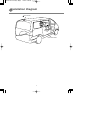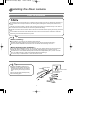
1
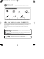
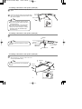
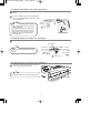
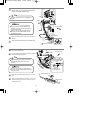
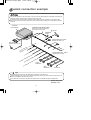
3-28510 BEC105 A5版(英語) 05.8.23 6:46 PM ページ1
REAR CAMERA
MODEL
INSTALLATION MANUAL
Be sure to read this installation manual thoroughly prior to installation and making connections. If installation
methods or non-standard parts not specified in this installation manual are used, accidents or injury may
result.
Professional techniques and experience are required in order to install this system. It is recommended that
you contact the place of purchase for installation to be carried out. After reading the installation manual
thoroughly, keep them in a safe place for later reference.
To dealers:
Give this installation manual to the customer after installation and all connections have been completed.
Contents
Before
installation
Components
For your safety in using the BEC105
Points to note after installing the rear camera
Installation Diagram
2
2
4
5
Installation
Installing the Rear Camera
Camera Angle Adjustment
6
11
Connections
System Connection Example
12
1
3-28510 BEC105 A5版(英語) 05.8.23 6:46 PM ページ2
Components
Check that all of the following components are present
Rear Camera Components
※ 1 Rear camera
x1
5 Cable rail
2 Bracket
3 Screw
x1
6 Harness affixing tape
x6
4 Double-sided tape
(M3x6)x 2
x2
(Spare) x 1
7 Waterproof cushion
x1
*The rear camera cable includes a 3-pin intermediate connector (male-female) to improve ease of installation.
For y our safety in using the BEC105
Warnings and caution signs, illustrated bellow, are posted throughout this manual as well as on the BEC105.
They show safe and correct ways to handle the product to prevent personal injury to you and others and avoid
damage to property.
Before reading through the manual, take time to read through and learn the important information listed in
this section.
This "WARNING" sign indicates a situation in which incorrect handling may result in
death or serious personal injury.
This "CAUTION" sign indicates a situation in which incorrect handling may result in
personal injury or may result solely in damage to property.
Tip
This section contains information that can help to prevent problems and
damage to the unit, and also contain other useful information.
2
3-28510 BEC105 A5版(英語) 05.8.23 6:46 PM ページ3
• This unit is intended for operation in DC 12volt,
negative-grounded vehicles only. Never use it in
24- volt vehicles such as heavy trucks or diesel
vehicles with cold-region specifications.
• Bundle cables and harnesses with electrical tape
or wire ties to prevent them from interfering with
moving parts. If they should entangle with the
steering wheel, shift lever or brake pedal, an
accident may result.
• Do not install this product in locations where it
may interfere with the operation of the steering
wheel, shift lever, brake pedal, etc. Otherwise,
an accident or injury may result.
• Do not disassemble or rebuild this product.
Doing so may cause an accident, fire or
electrical shock.
• To prevent damage to the vehicle, confirm the
locations of hoses, electrical wiring, and the fuel
tank prior to drilling holes to install this product.
Also, take care so that the product does not
interfere and/or not come in contact with them.
Otherwise, a fire may result.
• If an abnormal situation occurs, such as foreign
matter entering or liquid splashing on the
product, or smoke or a strange odor emitting
from the unit, shut off the product immediately
and consult the dealer from whom you
purchased it. Continued operation may cause an
accident, fire or electrical shock.
• When using an existing nut and/or bolt from the
vehicle to ground this product, do not use any
that secure parts of the steering or braking
systems. Otherwise, an accident may result.
• Do not install this product in locations where it
may obstruct the driver's view, or where it may
endanger passengers in the vehicle. Otherwise,
an accident or injury may result.
• Be sure to disconnect the negative terminal of
the vehicle's battery before prior to any
installation work. If you do not do this, the
positive and negative circuit may become
shorted and electric shocks or injury may result.
• If using a drill to make holes, wear protective
goggles to protect your eyes, otherwise debris
may get into your eyes and cause injury or
blindness.
• Do not allow the cable to touch metallic objects
when routing it. If it touches metallic objects, they
may become damaged and fire or electric
shocks may result.
• Specialized training and experience is required
in order to install and connect the camera. To
ensure safety, ask the place of purchase to
provide any installation and connection work. If
the unit is connected incorrectly, serious damage
to the vehicle may result.
• Keep the cable away from hot objects when
routing them. If the cable touches hot parts of the
vehicle, the insulation may melt and cause shortcircuits, which could result in fire or electric
shocks.
• When installing this product, be sure to use the
supplied mounting hardware. If parts other than
those supplied are used, the unit may be
damaged internally, or may not be held in place
securely and become dislodged.
• If changing the installation location of the
camera, ask the place of purchase in order to
ensure safe operation. Removing and installing
the camera requires specialized skills.
• Avoid installing the camera in places where it
cannot be installed securely or may be subjected
to excessive vibration. If this is not observed, the
camera may fall off and cause traffic accidents
and injury.
• The camera cannot be used for any purpose
other than as a vehicle-mounted camera.
Incorrect use of the camera may result in electric
shocks or injury.
• Connect the camera according to the instructions
given in this manual. If the camera is not
connected correctly, fire or other accidents may
result.
• The purpose of this camera is to enable the
driver to check behind the vehicle at times such
as when reversing the vehicle or parking it. It
should not be used for any other purpose.
• Be careful not to allow the cable to touch
threaded parts of the camera and moving parts
such as seat rails when routing them, otherwise
the cable may become damaged and shortcircuits may occur which could result in fire,
electric shocks or other accidents.
• Always be sure to check that the surrounding
area is safe when reversing the vehicle.
3
3-28510 BEC105 A5版(英語) 05.8.23 6:46 PM ページ4
Points to note after installing the rear camer a
- Method of use • Do not place too much reliance on the back-eye camera.
• The backeye camera is meant to be used as a supplementary aid to help in avoiding obstructions.
• If the lens is obscured by raindrops or similar, it may reduce in the effectiveness of the camera.
• The position of the images displayed on the screen will vary depending on the vehicle conditions (such as
number of passengers and laden weight). Be sure to check for safety behind and around the vehicle while
driving.
• Never reverse the vehicle while watching only the images produced by the camera.
Be sure to use the interior mirror and door mirrors also to check for safety behind and around the vehicle.
• The characteristics of the camera lens will make all obstructions on the screen appear differently from their
actual positions and distances.
- Handling • Do not subject the camera to strong shocks by hitting it firmly or knocking it against other objects.
If this is not observed, it may damage the camera or cause problems with operation.
• Do not subject the camera lens to naked flames or sudden changes in temperature (example, "hair dryer") or
hot water, otherwise it may damage the camera or cause problems with operation.
• Avoid using in direct sunlight for long periods of time. If this is not observed, burn-in of images may occur.
• The initial image that is displayed from the rear of the vehicle will be a white image (it may vary depending
on the model of camera connected), but the image will gradually stabilize.
• If the camera is used for long periods of time, the increase in temperature may cause white marks or
horizontal lines to appear. This is a characteristic of the CCD and is normal.
• Flickering may occur in the images if the camera is used underneath fluorescent light in 50 Hz power supply
areas. This is normal and is not the sign of a malfunction.
• Do not clean the backeye camera unit and lens, the bracket, or the camera cable with volatile chemicals
such as alcohol, kerosene, thinner or gasoline. Using such chemicals may cause warping, discoloration or
other damage.
• Do not use cleaning substances that contain abrasive powders. Using such substances will damage the
camera.
• If the lens area becomes dirty, wipe it gently with a soft cloth moistened with water. If the lens is rubbed
firmly with a dry cloth, it may scratch the lens.
• Do not damage the camera cable. Water vapor or water may get inside the camera through the damaged
section and cause problems with operation, fire, or electric shocks.
• If washing the vehicle with the backeye camera installed, do not apply water directly to the cabling to avoid
water getting inside the vehicle compartment.
• Do not wash the backeye camera unit using automatic vehicle washing equipment or high-pressure washing
equipment. If such equipment is used, the camera may fall off or water may remain inside the camera. This
could result in problems with operation, fire, or electric shocks.
• Periodically inspect the camera and the bracket. Check that the mounting screws are not loose and that the
adhesive areas are not peeling away. If the mounting screws are loose, they should be tightened. If this is
not done, the camera may come off and fall down, or pedestrians may touch it resulting in problems with
operation.
• If sunlight shines directly into the camera or other strong light (such as sunlight reflected from the bumper or
headlights) shines into the camera, it may cause vertical lines (smearing) to appear at the top and bottom of
the light source. This is normal and is not the sign of a problem.
4
3-28510 BEC105 A5版(英語) 05.8.23 6:46 PM ページ5
Installation Diag r am
1
Rear camera
Rear camera cable
5
3-28510 BEC105 A5版(英語) 05.8.23 6:46 PM ページ6
Installing the Rear camer a
Notes on installation
• The cables should be secured with tape or a similar securing method to prevent any obstructions while driving. If
they get wound around components such as the steering wheel, shifting lever or brake pedal, accidents may
result.
• Install the rear camera bracket so that the entire mounting side surface can be affixed securely to the vehicle. If
the contact surface area is insufficient, the camera may fall off while driving.
• Install the rear camera and the camera cable so that it dose not interfere with the opening and closing of the back
door.
• Do not install the camera where it will obstruct the driver's vision or where it will be an obstacle or obstruction
while driving, otherwise traffic accidents may result.
Tip
- Before installing • If the weather is very humid, do not install the camera outdoors.
(Humidity will cause the adhesive to become weaker and the camera may fall off while driving.)
• Be sure to read the installation manual for the main unit that the camera is being connect to.
- When performing the installation • For 24 hours after installing the camera, the vehicle can be driven without problems, but avoid spraying the
camera with water or exposing it to rain, Let it sit naturally without applying any excessive force to it.
• The adhesive force of the double-sided tape will be reduced at low temperatures (20°C) or less. Use a hair
dryer or a similar technique to warm the double-sided tape before attaching it.
• Do not use a dryer or a similar device on at the rear camera or lens.
Tip
• Check the installation position prior to
installing to ensure that the rear camera
and the camera cable does not interfere
with the opening and closing of the back
door.
• Do not peel the double-sided tape away
from its backing paper.
1 Rear camera
Front of vehicle
Check that there is
no interference
Back door
Front of vehicle
6
3-28510 BEC105 A5版(英語) 05.8.23 6:46 PM ページ7
1
Decide on the installation position for the rear
camera.
- If installing underneath a rear spoiler (example) -
Tip
Note the following when deciding on the
installation
position for the rear camera.
• Provisionally attach the rear camera with
tape and adjust its angle (see page 11) in a
position to view the rear of the vehicle.
When the double-sided tape has been used
once, the adhesive will be reduced if it is
used again.
• Install the rear camera in a position where
light from sources such as a high mounted
brake light will not shine into the camera
lens.
1 Rear camera
Front of vehicle
- If installing directly to the back door (example) -
1 Rear camera
Front of vehicle
7
3-28510 BEC105 A5版(英語) 05.8.23 6:46 PM ページ8
- If installing underneath a rear spoiler (example) 2
Wipe the installation surface free of any dirt, water or
grease.
3
Peel off the backing paper from the double-sided
tape on the bracket, and affix the bracket to a flat
part of the rear spoiler.
Front of vehicle
Tip
2 Bracket
• After affixing the bracket, push the bracket
firmly on the mounted surface ensure that it
is securely attached.
• The adhesive strength of the double-sided
tape will be reduced at low temperatures
(20°C) or less. Use a hair dryer or a similar
technique to warm the doublesided tape
before attaching it.
- If installing underneath a rear spoiler (example) 4
Install the rear camera to the bracket.
2 Bracket
Tip
• Install so that the "ECLIPSE" logo is facing
upward.
3 Screw
(M3x6)x 2
Front of vehicle
1 Rear camera
- If installing underneath a rear spoiler (example) 5
Pull the rear camera cable inside the back door
while securing it with the cable rails and
commercially-available clamp.
5 Cable rail
Tip
5 Cable rail
• The cable rails should be cut to appropriate
lengths.
Front of
vehicle
1 Rear camera
Clamp
8
3-28510 BEC105 A5版(英語) 05.8.23 6:46 PM ページ9
– If installing underneath a rear spoiler (example) –
6
Wipe the installation surface free of any dirt, water or
grease.
7
Peel off the backing paper from the double-sided
tape on the bracket, and affix the bracket to a flat
part of the back door.
Tip
• After affixing the bracket, push the bracket
2 Bracket
Front of
vehicle
firmly on the mounted surface ensure that it
is securely attached.
• The adhesive strength of the double-sided
tape will be reduced at low temperatures
(20˚C) or less. Use a hair dryer or a similar
technique to warm the double-sided tape
before attaching it.
– If installing directly to the back door (example) –
8
Install the rear camera to the bracket.
2 Bracket
Tip
• Install so that the "ECLIPSE" logo is facing
upward.
Front of vehicle
3 Screw
(M3x6)x 2
1 Rear camera
– If installing directly to the back door (example) –
9
Pull the rear camera cable inside the back door
while securing it with the cable rails.
5 Cable rail
Tip
Front of
vehicle
• The cable rails should be cut to appropriate lengths.
1 Rear camera
9
3-28510 BEC105 A5版(英語) 05.8.23 6:46 PM ページ10
10
Route the rear camera cable while securing it
with the cable rails, commercially-available cable
tie,and commercially-available clamp.
Clamp
Tip
Cable tie
Front of vehicle
• The cable rails should be cut to appropriate
lengths.
Clamp
• Confirm that the rear camera cable does
Front of vehicle
not get pulled and that the cable ties and
clamps do not come off when the back door
is opened and closed.
• Take care when routing the cable through
the trunk to ensure that rainwater cannot
get inside the vehicle.
5
11
Place the cable into the slit of the waterproof
cushion.
12
Attach the waterproof cushion to the weatherstrip.
Cable rail
7
13
Route the rear camera cable while securing it with
the harness affixing tape.
14
Cut the luggage finish plate so that the camera
cable does not get caught on it.
Weatherstrip
Waterproof cushion
Front of
vehicle
Front of vehicle
Camera cable
6
Harness affixing tape
Tip
• Check that there is no rib on the underside
Luggage finish plate
of the luggage finish plate at the notch
position.
3mm
3mm
Position with no
rib on underside
• Take care when routing the cable through
the trunk to ensure that rainwater cannot get
inside the vehicle.
15
6
Route the rear camera cable through to the main
Harness affixing tape
unit.
16
Wrap the intermediate connector of the rear
camera cable with harness affixing tape to
dampen any noise.
Camera cable
10
3-28510 BEC105 A5版(英語) 05.8.23 6:46 PM ページ11
Camer a Angle Adjustment
• When adjusting the camera images, apply the vehicle's parking brake and be sure to chock the wheels of the
vehicle so that the vehicle will not move, otherwise accidents or injuries may occur.
1
After connecting the rear camera cable to the
main unit, connect the battery cable.
- Main unit 2
Move the selector lever to the R position to
display images from behind the vehicle.
3
Loosen the adjustment screw and adjust the
angle of the camera so that the rear of the vehicle
(rear window, back door, rear bumper, etc.) are
visible as shown in the diagram.
Rear of vehicle
4
- Angle adjustment -
After adjusting the angle, securely tighten the
adjustment screw.
At this time, secure the bracket adjustment screw
so that it is at either end of the slot in the bracket.
1
Rear camera
Tip
3
• Prior to adjusting the rear camera angle,
check that gear was shifted into Park or
Neutral position.
• Be careful not to pull on the cable when
adjusting the angle of the rear camera.
• Check the adjustment screw regularly and
re-tighten if it becomes loose.
Screw (M3x6)
- Mounting adjustment -
11
3-28510 BEC105 A5版(英語) 05.8.23 6:46 PM ページ12
System connection example
• Never cut the insulation on the power cable or use it to power any other equipment. If the rated current capacity
of the power cable is exceeded, fire and electric shocks may result.
• The cables should be bound together with tape or with a similar technique so that they do not interfere with
driving. If they become wound around parts such as the steering wheel, shifting lever or brake pedal, accidents
may result.
MAIN UNIT
(sold separately)
ANTENNA EXTENSION CABLE
Be sure to use when connecting the
radio antenna to the vehicle.
1 BEC105
ANTENNA
PLUG
20P
4P
INTERCONNECTING CABLE
(Supplied with main unit)
GPS ANTENNA
(Supplied with main unit)
16P
llow
Ye
V
12 y)
+
Y pl
d
ER up
Re
TT t S
)
y
ite
l
BA anen
pp
/Wh
TO erm
Su
nge
r
a
e
r
e
P
(
O
w
Blu
(Po
n)
)
o
e
i
C
y
t
l
hit
AC
pp
ina
Su
e/W
(
um
TO
l
u
l
l
I
B
AY
H(
EL
ly)
TC
pp
AR
u
WI
S
N
S
(
N
HT
TE
NIT
LIG
AN
HU
D
R
C
A
A
WE
HE
FE
PO
TO
DO
TO
A
E
FRONT
NL
-O
SPEAKERS
N
R
TU
TO
REAR
SPEAKERS
1P
INTERCONNECTING CABLE
(Supplied with main unit)
ck
Bla
TO GROUND
Tip
• Install all components and route the cables before connecting up the main unit.
• The terminals at the rear of the main unit will vary depending on the type of main unit used. Always be sure to
refer to the installation manual for the main unit.
• If any cables are unconnected, wrap their ends with PVC tape or a similar technique to insulate them.
090003-28750700
0507DE(CN)
12