1
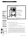
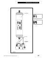
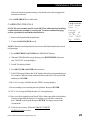
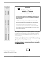
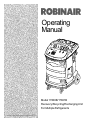
Operating Manual Model 17800B/17801B Recovery/Recycling/Recharging Unit For Multiple Refrigerants Model 17800B Recovery/Recycling/Recharging Unit 1 ROBINAIR Refrigerant Recovery, Recycling, and Recharging Design Certified by Station Underwriters Laboratories Inc.,® to meet SAE-J-1770 for recycling R-134a and R-12 using common refrigeration circuits. LISTED 80S2 Model: 17800B Volts: 115V 60 Hz Amps: 12.0 Refrigerants: R-12, R-134a, ARI 98 Class III, and ARI 98 Class IV Design Pressure: High 382 psig Low 171 psig Serial No.: Date Code: WARNING PRESSURIZED TANK CONTAINS LIQUID REFRIGERANT. OVERFILLING OF THE TANK MAY CAUSE VIOLENT EXPLOSION AND POSSIBLE INJURY OR DEATH. Safety devices requires the use of only authorized refillable refrigerant tanks. This includes Robinair Part Numbers 17506 and 34750 (50lb.) tank. Do not recover refrigerants into a non-refillable storage container! Federal regulations require refrigerant to be transported only in containers meeting DOT spec. 4BW or DOT spec. 4BA. ALL HOSES MAY CONTAIN LIQUID REFRIGERANT UNDER PRESSURE. Contact with refrigerant may cause injury. Wear proper protective equipment, including safety goggles. Disconnect hoses with extreme caution. HIGH VOLTAGE ELECTRICITY INSIDE PANELS. RISK OF ELECTRICAL SHOCK. Disconnect power before servicing unit. Refer to the operating manual. TO REDUCE THE RISK OF FIRE, avoid the use of an extension cord because the extension cord may overheat. However, if you must use an extension cord, the cord shall be No. 14 AWG minimum and keep the cord as short as possible. Do not use this equipment in the vicinity of spilled or open containers of gasoline or other flammable substances. Use this equipment in locations with mechanical ventilation that provides at least four air changes per hour or locate the equipment at least 18 inches off the floor. Make certain that all safety devices are functioning properly before operating the unit. Before operating, read and follow the instructions and warnings in the operating manual. CAUTION: RISK OF INJURY. THIS EQUIPMENT SHOULD ONLY BE OPERATED BY CERTIFIED PERSONNEL. Operator must be familiar with A/C systems, refrigerants and the dangers of pressurized components. Use this unit only with R-12, R-134a, and ARI 98 Refrigerant Classes III and IV systems only. This unit is not designed for any other purpose than recovering or recycling refrigerants! Do not mix refrigerant types! Additional health and safety information may be obtained from refrigerant and lubricant manufacturers. ATTENTION! Ce réservoir sous pression contient du frigorigène liquide. S’il est surchargé, ce réservoir peut exploser et causer des blessures ou la mort. ATTENTION. Débrancher avant la maintenance. ATTENTION. Pour réduire les risques d’incendie, ne pas utiliser de cordon prolongateur de section inférieure à 14 AWG de facon à éviter la surchauffe du cordon. ATTENTION. Utiliser seulement du frigorigène R-12 and R-134a. OPERATING NOTES Drain the System Oil Separator at the end of each recovery. The display will indicate when a filter-drier and vacuum pump oil change are required except if you are recovering from a burnout system. Then the filterdrier should be changed at the completion of that job. When switching refrigerant types, the unit must always be self-cleared. Non-condensables can be purged from the refillable tank during the recycling procedure. Get the temperature of the refrigerant you are recycling from the air purge gauge. Look at the pressure-temperature chart to find what the pressure should be at that temperature and compare it to what the air purge gauge pressure is. If the pressure on the air purge gauge exceeds the desired pressure by more than 10 psi, open the gauge for 30 seconds, then close it and re-check the pressure. Continue as needed during the recycling procedure. This equipment is protected by one or more of the following U.S. and foreign patents: US 4,523,897; 4,688,388; RE: 33,212; 4,768,347; 4,805,416; 4,878,356; 4,938,031; 5,005,369; 5,005,375; 5,038,578; 5,042,271; 5,063,749; 5,095,713; 5,181,391; 5,203,177; 5,231,842; 5,248,125; 5,493,869; 5,603,223; AUS 609,240; AUS 613,058; AUS 622,833; BRA P1 8803612; CAN 1,311,621; CAN 1,311,622; CAN 1,331,922; CAN 2,012,620; CAN 2,026,348; EUR 0 315 296 B1; EUR 0 329 321 B1; EUR 0 437 021 B1; MEX 16028; SAF 88/4981. Other U.S. and Foreign Patents Pending. 123941 (04/01) 2 Manufactured by Robinair, SPX Corporation, Montpelier, OH 43543-1952 Printed in U.S.A. © 2001 Robinair, SPX Corporation Introduction This manual contains important safety procedures concerning the operation, use and maintenance of this product. Failure to follow the instructions contained in this manual may result in serious injury. If you are unable to understand any of the contents of this manual, please bring it to the attention of your supervisor. Do not operate this equipment unless you have read and understood the contents of this manual. TABLE OF CONTENTS Glossary of Terms ............................................................................................................... 4 Introduction .......................................................................................................................... 4 General Operating Guidelines .............................................................................................. 5 Set Up Instructions ......................................................................................................... 6-11 Recovery Procedures ........................................................................................................ 12 Changing Refrigerant Types .............................................................................................. 14 A/C-R System Evacuation ................................................................................................. 16 Recycling Procedures ........................................................................................................ 17 Charging Procedures ......................................................................................................... 18 Correcting An Incomplete Transfer .................................................................................. 19 Adding Refrigerant to the Tank .................................................................................... 20-21 Operating Overview ..................................................................................................... 22-24 Changing the Vacuum Pump Oil ....................................................................................... 25 Changing the Compressor Oil and Filter-Drier ............................................................. 26-27 Confirming the Scale Checklist .......................................................................................... 28 Correct Weight Verification ......................................................................................... 28-29 Calibrating the scale ........................................................................................................... 29 Calibrating the UL Circuit..................................................................................... .33-31 Checking for Leaks ........................................................................................................... 32 Using the Control Panel ..................................................................................................... 33 Keypad Functions .............................................................................................................. 34 Using the Digital Display .............................................................................................. 35-36 Using the Diagnostic Mode .......................................................................................... 37-38 Using Display Codes ..................................................................................................... 39-40 Replacement Parts ............................................................................................................. 41 Flow Diagram .................................................................................................................... 42 Wiring Diagram ................................................................................................................. 43 Troubleshooting ............................................................................................................. 44-47 Limited Warranty ............................................................................................................... 48 See the Index on page 49 for a listing of all procedures and diagrams. Model 17800B Recovery/Recycling/Recharging Unit 3 Introduction The 17800B is a complete A/C-R service center. It recovers, recycles and recharges a wide range of refrigerants — from existing refrigerants to new substitutes and blends. With its multi-refrigerant capabilities, it is ideal for trucks, buses and refrigerated trailers, as well as in-plant maintenance and other accessible installations. The built-in manifold means the entire service procedure can be done with just one hook-up. A microprocessor controls the unit’s functions; evacuation time and the amount of refrigerant to be recharged can be programmed at the beginning of the job. Prompts lead you through programming and alert you when the filter and vacuum pump oil need to be changed. This unit is UL-listed and meets the SAE specifications for recycled refrigerant. It is also designed to be compatible with existing service equipment and standard service procedures. This unit is simple to operate and has many user-friendly features: • a built-in 6 cfm vacuum pump for quick, yet thorough evacuation, • a plastic enclosure for safe and easy manuevering around vehicles without the worry of scratches. • an electronic scale that weighs recovered refrigerant and recharges by weight for greatest accuracy, • a pressure/temperature chart mounted directly above the gauges — with just a quick glance you can tell the temperatures in the system, • large diameter wheels that make it easy to move the unit, IMPORTANT! To validate your warranty, complete the warranty card attached to your unit and return it within ten days from date of purchase. GLOSSARY OF TERMS A/C-R A/C-R System Unit Tank 4 Air conditioning or refrigeration The air conditioning or refrigeration system serviced The refrigerant recovery, recycling, recharging unit The refillable refrigerant tank © 2001 Robinair, SPX Corporation Introduction GENERAL OPERATING GUIDELINES • The voltage at the unit must be ±10% of the unit’s rated voltage. Extension cords must be a minimum of 14 AWG and kept as short as possible. • To interrupt any procedure (other than clearing), press HOLD/CONT. Press HOLD/CONT again to resume operation. • The system oil should be drained at the end of every recovery or recycling procedure, during the clearing process, or whenever oil is visible in the sight glass. • The indicator light will tell you the state of the refrigerant coming into the unit during recovery. ON is liquid, OFF is vapor. The light is not used for recycling since the refrigerant coming from the tank will always be a liquid. • Some tanks have slightly different valve configurations. Be sure to connect the red hose to the GAS (vapor) valve and connect the blue hose to the LIQUID valve. • To insure that the scale readings are as accurate as possible, be sure the tank is not touching the sides of the cart before each procedure. • To minimize mixing of refrigerants, follow the steps in Changing Refrigerant Types when switching between refrigerant types. • When the unit is first turned on, the display shows either: “134a” — indicates R-134a automotive refrigerant using 1/ ” Acme fittings, 2 “R12” — indicates all other refrigerant types using 1/4” flare fittings, or “door” — indicates the unit has been cleared; select R-12 or R-134a. Be sure you have selected the correct refrigerant type. • Be sure to use the correct hose set for the refrigerant type selected: Hose Set R-134a automotive R-12 automotive All other refrigerant types Tank Hoses (3) 36”, 1/2” Acme with double Quick Seal 36”, 1/4” flare with double Quick Seal 36”, 1/4” flare with single Quick Seal Model 17800B Recovery/Recycling/Recharging Unit System Hoses (2) 96”, one Quick Seal with one quick coupler 96”, 1/4” flare with double Quick Seal 96”, 1/4” flare with ball valve 5 Set Up Instructions Before you begin any procedure, familiarize yourself with the components of your unit. High Side Port Lockout Door Low Side Port Tank Liquid Valve Red Vapor Hose Blue Liquid Hose Yellow Air Purge Hose Tank Vapor Valve Air Purge Fitting 50 lb. (23 kg) Unit Tank Scale Assembly Diagram of Unit’s Components — External View Oil-less Compressor Filter-Drier Hermetic Compressor HI-P Access Port Vacuum Pump INST0917 Diagram of Unit’s Components — Internal View 6 © 2001 Robinair, SPX Corporation Set Up Instructions Pressure/Temperature Chart Door Screw System Oil Drain Valve Door Screw INST0918 Diagram of Unit’s Components — Side Views Air Purge Gauge Liquid/Vapor Indicator System Oil Indicator Low Side Gauge High Side Gauge Display Air Purge Valve Oil less Compressor Protector Main Power Switch INST0919 Unit Circuit Breaker Keypad Low Side Valve High Side Valve Diagram of Control Panel and Keypad Model 17800B Recovery/Recycling/Recharging Unit 7 Set Up Instructions Before starting the set up procedures, open the system oil drain valve and allow the unit to depressurize. 1. Plug the unit into a proper voltage outlet. CAUTION! Avoid the use of an extension cord because the extension cord may overheat. However, if you must use an extension cord, use a No. 14 AWG minimum and keep the cord length to 25 feet (7.6 meters) or less. 2. Be sure the oil drain valve on the side of the unit is in the CLOSED position. 3. Turn on the unit. The display flashes “door.” Slide the lockout door (in the upper left corner of the back of the unit) to expose the 1/4” flare fittings for R-12, or the 1/2” Acme fittings for R-134a then press SHIFT/RESET to continue. 4. Connect either of the automotive hose sets as follows: • Connect the 36” red hose to the RED fitting on the back of the unit • Connect the 36” blue hose to the BLUE fitting on the back of the unit HIGH LOW • Connect the 36” yellow hose to the YELLOW fitting on the back of the unit RED BLUE YELLOW (R-134a shown— R-12 same order and colors) INST0920 CAUTION! R-134a automotive Diagram of Hose Connections Lockout Box systems have 1/2” Acme fittings (per SAE specifications) to avoid cross-contamination with systems using 1/ ” flare fittings. Do not attempt to adapt your unit for the other refrigerant — 4 system failure will result! 8 © 2001 Robinair, SPX Corporation Set Up Instructions 5. A new tank comes with a dry nitrogen charge of 5 to 10 psi to keep it clean and dry during shipment. Purge the nitrogen charge on the R-12 (gray and yellow) tank by opening the GAS (vapor) valve on the tank. Vent the pressure to the atmosphere, then close the valve. 6. Place the unit tank inside the ring on the scale platform on the back of the unit. Loop the tank strap through the tank collar and secure the latch end of the strap to the metal loop at the other end of the strap. Use the thumb screw on the scale ring to tighten the tank to the scale platform. 7. Connect the 36” red hose to the red valve on the tank and open the valve. Connect the 36” blue hose to the blue valve on the tank and open the valve. Connect the 36" yellow hose to the air purge fitting on the tank. 8. Open both the low and high side valves on the control panel. Tank Strap Unit Tank Scale Thumb Screw INST0921 Placing the Tank on the Scale Model 17800B Recovery/Recycling/Recharging Unit 9 Set Up Instructions The VacuMaster® vacuum pump is shipped without oil in the reservoir. Before starting the unit, you must fill the pump with oil. Two 16-ounce (472 milliliters) bottles of oil are included with your unit. 9.Remove the door access screws from the right side of the unit. Open the door. Important! Be sure the pump is running when adding oil. Do not overfill the pump. The approximate oil charge is 13 oz. (384 milliliters). 10. Remove the black plastic plug from the pump’s oil fill port. Attach the flexible spout and cap to the bottle of oil included with your unit. This makes it easier to fill the pump. 11. Add one-half of a bottle of vacuum pump oil to the vacuum pump. 12. Press SHIFT/RESET and ENTER at the same time, then press “1.” The vacuum pump will start and run continuously. While the pump is running, pour oil into the pump’s oil fill port until the level of oil is even with the line of the pump reservoir sight glass. Replace the black plug on the oil fill port. 13. Let the pump run for about five (5) minutes to remove any air from the unit. 14. To turn off the pump, press HOLD/CONT. Then press SHIFT/RESET to exit the diagnostics mode. 15. Connect the blue 96" Hose the the low side port, and the red 96" hose to the high side port on the back of the unit. Oil Filler Tube Inlet Pump Exhaust Oil Fill Port Sight Glass Oil Drain Fitting Diagram of Vacuum Pump Components 10 © 2001 Robinair, SPX Corporation Set Up Instructions Before using a new tank, you must purge its nitrogen charge and pull it into a vacuum. The 50 lb (23kg) unit tank must be filled with refrigerant before the unit is ready for use. Tank Fill 17. Connect the 96" Blue low side hose to the fitting on the source tank. If using R134a you may need the 1/2" acme to low side adapter included in the accessory kit. 18. Press SHIFT/RESET and ENTER at the same time, then press 2. The unit will begin transfering refrigerant from the source tank to the unit tank. 19. The unit will fill the recovery tank up to 30 lbs of refrigerant and automatically stop. The display will flash "CPL" when the process is complete. 20. To discontinue tank fill at any time press HOLD/CONT. WARNING! Always wear safety goggles when working with refrigerant. Use only authorized refillable refrigerant tanks. Disconnect hoses with extreme caution! All hoses may contain refrigerant under pressure. Read and follow all warnings at the beginning of this manual before operating the unit. Model 17800B Recovery/Recycling/Recharging Unit 11 Operating Instructions RECOVERY PROCEDURES WARNING! Always wear safety goggles when working with refrigerant. Use only authorized refillable refrigerant tanks. Disconnect hoses with extreme caution! All hoses may contain refrigerant under pressure. Read and follow all warnings at the beginning of this manual before operating the unit. Before beginning recovery, be sure your unit is set up as described in the Set Up Instructions. Also be sure there is vacuum pump oil in the vacuum pump. 1. Connect the high and low side hoses to the A/C-R system, as you would normally connect your manifold gauge set. 2. Be sure both the high and low side valves on the control panel are open. Also be sure both valves on the tank are open. 3. Plug the unit into the proper voltage outlet, and turn on the MAIN POWER switch. The display shows either “134a” (which indicates R134a automotive refrigerant that uses 1/2” Acme fittings) or “R12” (which indicates all other refrigerant types that use 1/4” flare fittings.). The display may flash "door", which indicates the unit is cleared and can be set up for any refrigerant type. 4. Press RECOVER. Air Purge Gauge Liquid/Vapor Indicator System Oil Indicator Low Side Gauge High Side Gauge Display Air Purge Valve INST0919 Main Power Switch Unit Circuit Breaker Oil less Compressor Protector Keypad Low Side Valve High Side Valve Diagram of Control Panel 12 © 2001 Robinair, SPX Corporation Operating Instructions The “CL-L” message shows on the display if there is pressure in the unit, and a selfclearing process of the components begins. You can press HOLD/CONT to bypass clearing if an accurate recovery amount is not required. Otherwise, the compressor will start and the “CL-L” message remains on the display. This process takes from 20 seconds to four minutes to complete. Once the clearing is complete, the unit automatically begins to recover refrigerant from the system. If there is no internal pressure in the unit, refrigerant recovery begins immediately. CAUTION! If the A/C system pressure is 25 psi or less, the message “CH-P” appears on the display to alert you not to attempt recovery from an empty system. Do not press HOLD/CONT to continue the recovery process unless you know the A/C system contains refrigerant. The display shows that the unit is in the RECOVER mode and the AUTOMATIC cycle. You can monitor the amount of refrigerant removed from the system by watching the display. The compressor shuts off automatically when recovery is complete (at approximately 13 inches of vacuum). The display shows the “CPL” message and then alternately flashes the weight of refrigerant recovered. 5. To assure complete recovery of refrigerant, wait for five (5) minutes and watch the manifold gauges for a rise in pressure above “0.” If a rise occurs, press HOLD/ CONT. Repeat as needed until the system pressure holds for two (2) minutes. Weight Example CAUTION! Drain the oil from the separator only after each recovery. Do not completely depressurize the oil separator; immediately close the valve when oil is completely drained in the next step. The lower right corner of the display will indicate “OIL (OUNCES)” as a reminder. 6. Be sure the oil catch bottle is empty, then slowly open the oil drain valve, and drain the oil into the oil catch bottle. This oil was removed from the A/C system during recovery. It must be replaced with new oil. When all the recovered oil has completely drained, immediately close the valve and record the amount of oil in the bottle. Dispose of waste oil in an appropriate manner. If the recovery tank fills completely: • The compressor shuts off; the digital display shows the message “FULL.” • Change the tank. The A/C system is now empty. Make any repairs at this time. Model 17800B Recovery/Recycling/Recharging Unit 13 Operating Instructions High Side Port Lockout Door Low Side Port Tank Liquid Valve Red Vapor Hose Blue Liquid Hose Yellow Air Purge Hose First! Perform "RECOVERY PROCEDURES" before starting "CHANGING REFRIGERANT TYPES". Tank Vapor Valve Air Purge Fitting 50 lb. (23 kg) Unit Tank Scale Assembly Diagram of Unit’s Components — External View Important! Before changing refrigerant types, be sure the red high side and blue low side hoses are disconnected from the A/C system. CHANGING REFRIGERANT TYPES 1. Be sure the red high side and blue low side hoses are disconnected from the A/C system, then open the manifold and tank valves. 2. Press and release SHIFT/RESET until the “Clr” message appears. 3. Press HOLD/CONT to start the system oil separator clearing process. AUTOMATIC 14 During the system oil separator clearing process, the compressor is activated and the “OIL” message displays. The compressor will stop while the unit equalizes pressure and the “OIL” message will continue to display. When the unit reaches the correct pressure, the display alternately flashes the messages “OIL” and “drn.” Open the system oil drain valve to drain the oil. After all oil has drained, close the oil drain valve. The message changes to “Cont.” Press any key to complete the oil separator clearing process. When compressor stops again, the message changes to "CL-c." © 2001 Robinair, SPX Corporation Operating Instructions 4. If you need to change hoses for the next refrigerant type, go to Step 5. If you do not need to change hoses, press SHIFT/RESET and go to Step 6. 5. To start the self-clearing process, press VACUUM while the “CL-c” message is displayed. The “Clr” message then displays and the vacuum pump runs for 5 minutes before shutting off automatically. The “door” message will then display. 6. Close the tank valves and disconnect the red, blue and yellow hoses from the tank. Then remove the tank from the unit. 7. If you are using the same hoses for the next refrigerant type, go to Step 11. If you need to change the hoses, go to Step 8. 8. Disconnect all five (5) hoses from the lockout box fittings. If you need to change the door position on the lockout box, go to Step 9. If you do not need to change the door position, go to Step 10. 9. Slide the door on the lockout box to expose the fittings needed for the next refrigerant type. 10. Connect the correct hoses for the next refrigerant to the fittings in the lockout box. Be sure to use the correct hose set for the refrigerant type selected: Hose Set R-134a automotive R-12 automotive All other refrigerant types Tank Hoses (3) 36”, 1/2” Acme with double Quick Seal 36”, 1/4” flare with double Quick Seal 36”, 1/4” flare with single Quick Seal System Hoses (2) 96”, one Quick Seal with one quick coupler 96”, 1/4” flare with double Quick Seal 96”, 1/4” flare with ball valve 11. Place a tank (already set up for the next refrigerant) on the unit. Connect the red, blue and yellow hoses to the appropriate tank fittings. The unit is now ready to process the next refrigerant type. Model 17800B Recovery/Recycling/Recharging Unit 15 Operating Instructions A/C-R SYSTEM EVACUATION WARNING! Always wear safety goggles when working with refrigerant. Use only authorized refillable refrigerant tanks. Disconnect hoses with extreme caution! All hoses may contain refrigerant under pressure. Read and follow all warnings at the beginning of this manual before operating the unit. 1. Be sure the high and low side hoses are connected to the A/C-R system and that the high and low side valves are open. 2. Press SHIFT/RESET to toggle the display to show “PROGRAM VACUUM MINUTES 15.00.” Fifteen minutes is the default time for evacuation. To change the time, press the appropriate keys to display the desired time. Then press ENTER. HOLD The longest time that can be programmed is 98.99 (98 minutes and 99 seconds). 3. Press VACUUM to start evacuation. The display counts down the time remaining. If the message “U-HI” appears, you have 25 psi or greater of pressure at the inlet. You must recover that pressure to continue. If necessary, press RECOVER. 4. When the programmed time has expired, the vacuum pump will automatically shut off and the display will show “CPL.” Press any key to exit vacuum mode. To run the vacuum pump continuously, program the time to “99.00,” press ENTER, then press VACUUM. The pump will start and the display will show “CON AUTOMATIC VACUUM.” To turn the vacuum pump off, press HOLD/CONT. 16 © 2001 Robinair, SPX Corporation Operating Instructions RECYCLING PROCEDURES WARNING! Always wear safety goggles when working with refrigerant. Use only authorized refillable refrigerant tanks. Disconnect hoses with extreme caution! All hoses may contain refrigerant under pressure. Read and follow all warnings at the beginning of this manual before operating the unit. 1. Be sure both valves on the tank are open. 2. Press and hold SHIFT/RESET and then press “1” to start the recycling process. If the recovery tank is full, the display will show the message “FULL.” Press HOLD/CONT to resume operation. 3. After about five (5) minutes of recycling, the tank temperature should equalize. You can then purge non-condensables. 4. To purge non-condensables, check the air purge gauge to find the temperature of the refrigerant. Use that temperature to find the correct pressure for that refrigerant on the pressure/temperature chart on the top of the unit. Compare the pressure from the chart to the pressure shown on the gauge. If the gauge pressure exceeds the target pressure by more than 10 psi, open the air purge valve on the control panel for about 30 seconds to release NonPressure Range non-condensables from the tank. Then Acceptable Condensables 190 to 200 psig Present close the air purge valve and allow the tank to stabilize for about 30 seconds. Check the air purge gauge again. Repeat this step as necessary during the recycling procedure. 5. To stop recycling, close the tank’s LIQUID valve. The unit will pull into a vacuum and shut off automatically. Press any key to exit recycle mode. Important! Youcanstoprecyclinginstantlyby pressing HOLD/ CONTthenSHIFT/ RESET,butthiscan leaveliquidrefrigerant in the low side of the unit. Closingthetanks LIQUIDvalveisthe recommended method. Target Pressure of R-22 at 98° is 190 psig INST0154 Diagram of Air Purge Gauge Model 17800B Recovery/Recycling/Recharging Unit 17 Operating Instructions CHARGING PROCEDURES WARNING! Always wear safety goggles when working with refrigerant. Use only authorized refillable refrigerant tanks. Disconnect hoses with extreme caution! All hoses may contain refrigerant under pressure. Read and follow all warnings at the beginning of this manual before operating the unit. The unit will display the message “CHECK REFRIGERANT” if there is less than six (6) pounds of refrigerant in the tank. The charging system will not function if this message is displayed. If you try to charge in this situation, the display will also show “Add HOLD” to let you know that refrigerant needs to be added to the tank. You should add more refrigerant to the tank than what is needed for charging (see Adding Refrigerant to the Tank). To check the weight of refrigerant in the tank, press and hold SHIFT/RESET then press ENTER to access the diagnostic mode. Press “7” to display the weight of refrigerant in the tank. Press SHIFT/RESET again to exit the diagnostic mode. Follow the A/C-R system manufacturer’s instructions regarding specific recharging specifications. You must replace any oil lost from the A/C-R system during recovery with new oil. Dispose of waste oil in an appropriate manner. 1. Open the high side valve and, if allowable, the low side valve on the unit’s control panel. 2. Press SHIFT/RESET until the message “CHG” appears on the display. 3. Press CHG and enter the weight of the refrigerant to be charged. Weight Example* 4. Press ENTER. The display will flash to indicate that the charge amount has been recorded in the unit’s memory. 5. Press CHG again to begin the charging process. Weight Example* 6. The display will show the message “AUTOMATIC” and the amount programmed for recharging. The display counts down to zero as charging proceeds. 7. When charging is complete, the display shows the message “CPL.” If the unit beeps continuously, the transfer of refrigerant has stopped before the charging procedure was completed (see Correcting An Incomplete Transfer). *Enter the correct weight for your application. 18 © 2001 Robinair, SPX Corporation Operating Instructions 8. Close the high and low side valves on the control panel and start the A/C-R system. Compare the gauge readings to the manufacturer’s specifications. 9. Turn off the A/C-R system and disconnect the high side hose from it. 10. Start the A/C-R system and open both the high and low side valves. This will pull the portion of the programmed charge that is trapped in the hoses into the low side of the A/C-R system. 11. At the lowest recommended operating pressure, close the low side valve and turn off the A/C-R system. Disconnect the low side hose from the system. 12. Close the high side valve and turn off the MAIN POWER switch. CORRECTING AN INCOMPLETE TRANSFER If the scale value does not change for 30 seconds, the unit beeps continuously to indicate that the transfer of refrigerant was not completed. There are two reasons for an incomplete transfer of refrigerant: • The pressure in the A/C-R system is equal to the pressure in the tank. The unit produces an audible signal and shows the weight remaining to complete the transfer. 1. Close the high side valve on the control panel. 2. Disconnect the high side hose from the A/C-R system. 3. Continue with Step 9 in Charging Procedures. • The display shows the message “CHECK REFRIGERANT” because there is not enough refrigerant in the tank. 1. Press HOLD/CONT to interrupt the transfer. 2. Be sure both valves on the tank are closed, then disconnect and remove the tank from the unit. Replace it with a tank containing additional refrigerant. 3. Press HOLD/CONT again to resume the transfer. Model 17800B Recovery/Recycling/Recharging Unit 19 Operating Instructions ADDING REFRIGERANT TO THE TANK CAUTION! R-134a systems have special fittings (per SAE specifications) to avoid cross-contamination with other refrigerant systems. Read and follow all warnings given at the beginning of this manual. NOTE: Purchase only tanks of R-134a refrigerant that have 1/2 inch (1.2cm) I M P O R T A N T ! Acme threads. This is necessary to match the hose adapter. When setting up 1. Connect the 96-inch (244 cm) blue low side hose to the unit's low-side port. for new types of refrigerant, a clearing process NOTE: Disposable tanks have only one valve and most must be turned upside down to transfer liquid. If you are using a disposable tank, follow the instructions on the will have to be side of the tank to obtain a liquid supply. performed. 2. When using R-12 connect the 6-inch (15.2-cm) yellow adapter to the source tank liquid valve first. Then connect the 96-inch (244-cm) blue lowside hose to the adapter. When using R-134a, connect the low-side connector port adapter to the source tank liquid valve first. Then connect the blue 96-inch (244-cm) lowside hose directly to the adapter. 3. Open the LIQUID valve on the source tank (there is only one valve on a non-refillable tank.) 4. Close the high-side manifold valve and open the low-side manifold valve on the front panel of the unit. Open both valves on the unit tank. 5. Press SHIFT/RESET and ENTER at the same time to access the diagnostic mode. The display shows the message "FUNC." 6. Press 2 to begin transferring refrigerant. The display shows the “Add” message for about two seconds, then shows the amount of refrigerant transferred. 7. Transfer stops automatically and the display shows the “CPL” message when the source tank is empty and has been pulled to a partial vacuum or the weight of refrigerant in the unit tank reaches 37 pounds. The display toggles between “CPL” and the weight in the tank . 20 © 2001 Robinair, SPX Corporation Operating Instructions (Adding Refirgerant to the Tank continued) This process takes about 45 minutes. You can interrupt it at any time by pressing HOLD/CONT once. Press HOLD/CONT again to resume operation, or press SHIFT/RESET to end the process. The transfer of new refrigerant is limited by weight to leave space (about 6 pounds of refrigerant) in the unit tank for recovery purposes. 8. When using R-12, close the supply valve on the source tank (when using a disposable tank, turn it right side up first). Carefully disconnect the 96 inch (244-cm) blue low-side hose from the 6-inch (15.2-cm) yellow adapter, and then remove the yellow adapter from the source tank. When using R-134a, close the supply valve on the source tank, (when using a disposable tank, turn it right side up first). Carefully disconnect the 96 inch (244-cm) blue low-side hose from the low-side connector port adapter and then remove the adapter from the source tank. 9. Press RECOVER. The hose will be pulled into a partial vacuum and the unit will turn off automatically. If the hose is partially clear, the unit will display "CH-P". Press HOLD/CONT to finish clearing the hose. Close the low-side manifold valve. 10. Connect the 96-inch (244-cm) red high-side hose to the unit's high-side port. You can also attach an oil injector to the unit's low-side port. Oil injectors will not connect to the wrong ports. The R-12 oil injector has a ¼ inch flare connector; the R-134a oil injector has a ½ Acme connector. Any non-condensable gases in the tank can be removed during the recycling sequence. Your unit is now ready for use. Model 17800B Recovery/Recycling/Recharging Unit Weight Example * * The display shows the weight of refrigerant added to the tank. IMPORTANT! Be sure to close both tank valves when the unit is not in use. Inspect the unit periodically for leaks. The manufacturer of the recovery/recycling unit does not reimburse for lost refrigerant. 21 Operating Overview This overview is designed as a quick reference when using your unit. Read and follow all warnings in the operating manual. RECOVERY OVERVIEW 1. Connect the high and low side hoses to the A/C-R system. 2. Check the manifold gauges. There must be pressure to recover refrigerant. 3. Be sure both the high and low side valves on the control panel are open. Also be sure both valves on the tank are open. 4. Plug the unit into the proper voltage outlet, then turn on the MAIN POWER switch. 5. Press RECOVER: • If there is pressure in the unit, the self-clearing process starts. • If there is no internal pressure, refrigerant recovery begins. • The unit then shows “RECOVER AUTOMATIC” and the weight of refrigerant being recovered into the tank. 6. Once the recovery and/or self-clearing procedure is complete, the compressor will shut off automatically. The display will flash “CPL” and the weight of refrigerant recovered. 7. If the A/C-R system pressure rises above zero, you can press HOLD/CONT to recover the remaining refrigerant. 8. The display also shows “OIL (OUNCES).” This is a reminder to drain the system oil separator into a suitable container by opening the ball valve on the side of the unit. Weight Example You must replace any oil lost from the A/C-R system during recovery with new oil. Dispose of waste oil in an appropriate manner. EVACUATION OVERVIEW 1. Be sure the high and low side hoses are connected to the A/C-R system and that the high and low side valves are open. 2. Press SHIFT/RESET to toggle the display to show “PROGRAM VACUUM MINUTES 15.00.” Fifteen minutes is the default time for evacuation. To change the time, press the appropriate keys to display the desired time. Then press ENTER. 22 © 2001 Robinair, SPX Corporation Operating Overview The longest time that can be programmed is 98.99 (98 minutes and 99 seconds). 3. Press VACUUM to start evacuation. The display counts down the time remaining. If the message “U-HI” appears, you have 25 psi or greater of pressure at the inlet. You must recover that pressure to continue. If necessary, press RECOVER. 4. When the programmed time has expired the vacuum pump will automatically shut off and the display will show “CPL.” To run the vacuum pump continuously, program the time to “99.00,” press ENTER, then press VACUUM. The pump will start and the display will show “CON AUTOMATIC VACUUM.” To turn the vacuum pump off, press HOLD/CONT. RECYCLING OVERVIEW 1. Be sure both valves on the tank are open. Press and hold SHIFT/RESET and then press “1” to start the recycling process. 2. When the tank temperature equalizes (after about five minutes of recycling time), purge non-condensables from the tank. To purge, use the air purge gauge to determine the temperature of the refrigerant. Then use the pressure/temperature chart on the top of the unit to determine the correct pressure for that refrigerant. If the gauge pressure exceeds the target pressure by more than 10 psi, open the air purge valve for about 30 seconds and release non-condensables from the tank. 3. Close the air purge valve and let the tank stabilize (about 30 seconds). Check the air purge gauge again. Repeat Steps 2 and 3 as necessary during the recycling process. 4. Close the tank's LIQUID valve to stop the recycling process. The unit will pull into a vacuum and shut off automatically. CHARGING OVERVIEW Follow the manufacturer’s recommendation for charging. You must replace any oil lost from the A/C-R system during recovery with new oil. Dispose of waste oil in an appropriate manner. 1. Open the high side valve and, if allowable, the low side valve. 2. Press CHG and enter the weight of the refrigerant to be charged. 3. Press ENTER, then press CHG again. The display counts down to zero, then shows the “CPL” message when complete. Model 17800B Recovery/Recycling/Recharging Unit Important! You can stop recycling instantly by pressing HOLD/ CONT then SHIFT/RESET, but this can leave liquid refrigerant in the low side of the unit. Closing the tank’s LIQUID valve is the recomm e n d e d method. 23 Operating Overview 4. Close the high and low side valves and start the A/C-R system. Compare the gauge readings to the manufacturer’s specifications. 5. Turn off the A/C-R system and disconnect the high side hose from it. 6. Start the A/C-R system and open both manifold valves to pull refrigerant from the hoses. Weight Example* 7. At the lowest recommended operating pressure, close the low side valve and turn off the A/C-R system. Disconnect the low side hose. 8. Close both manifold valves and turn off the MAIN POWER switch. Weight Example* *Enter the correct weight for your application. 24 © 2001 Robinair, SPX Corporation Maintenance Procedures CHANGING THE VACUUM PUMP OIL When the vacuum pump has run for a total of 10 hours, the “OIL” message will flash on the display to signal that an oil change is needed. To change the vacuum pump oil, follow these steps: 1. Turn on the MAIN POWER switch. The display shows the selected refrigerant type. 2. Press SHIFT/RESET and the messages “PROGRAM VACUUM MINUTES 15:00” display. 3. Press VACUUM. The display shows the “OIL” message. 4. Remove the door access screws from the right side of the unit. Open the door. 5. Remove the black plastic plug on the oil fill port. 6. Remove the oil drain cap from the vacuum pump, then drain the contaminated oil into a suitable container (be sure to dispose of it properly). Replace the oil drain cap. 7. Attach the flexible spout and cap to the oil bottle and pour approximately six (6) ounces of vacuum pump oil into the oil fill port. 8. Be sure the manifold valves are closed, then press SHIFT/RESET and ENTER at the same time to reset the ten-hour timer. 9. Press VACUUM. While the pump is running, slowly add new vacuum pump oil until the oil level is even with the line on the reservoir’s sight glass. 10. Replace the black plastic plug on the oil fill port. Oil Filler Tube Pump Exhaust Inlet Oil Fill Port Sight Glass Oil Drain Fitting Diagram of Vacuum Pump Components Model 17800B Recovery/Recycling/Recharging Unit 25 Maintenance Procedures CHANGING THE FILTERYou should change the filter-drier whenever refrigerant has been recovered from a burnout system or when the display shows the “CH-F” message (which means that the unit has recovered 200 pounds of refrigerant since the last change). To change the filter/drier follow these steps: 1. Press and hold SHIFT/RESET and then press FILTER. The compressor will start and the display will show the messages “FIL” and “AUTOMATIC.” 2. The compressor will shut off when the vacuum switch trips, and the display will show the messages “FIL” and “HOLD.” 3. Turn off the MAIN POWER switch and unplug the unit. 4. Remove the door access screws from the right side of the unit. Open the door. 5. Disconnect the hose from the top of the filter-drier and unscrew the filter-drier by rotating it counter clockwise. (you may need a 5/8" wrench to break it loose.) 6. Open the new filter-drier and generously lubricate the O-ring with vacuum pump grease. Also lubricate the gasket in the end of the hose which connects to the top of the filter-drier. 7. Replace the greased o-ring into the groove in the manifold. Screw the new filterdrier into place. Reattach the hose with the greased gasket to the top of the filterdrier. 8. Once the new filter-drier is correctly installed. Close the cabinet door, and replace the door access screws. 9. Turn on the MAIN POWER switch. Important: Do not remove the filter-drier from its sealed bag until you are ready to use it. 26 10. Press HOLD/CONT. The vacuum pump will start, the display will show the messages "FIL AUTOMATIC", the pump will run for about 2 minutes, and shut off. The display will show the message "CPL". This procedure automatically resets the and filter-drier change counter for another 200 pounds of refrigerant. © 2001 Robinair, SPX Corporation Maintenance Procedures Filter-Drier O-ring Oil Return Manifold INST0922 Diagram of Filter-Drier Model 17800B Recovery/Recycling/Recharging Unit 27 Maintenance Procedures CONFIRMING THE SCALE CHECKLIST Important: Check the scale accuracy every three months. Blank Display or No Warnings. Check wire connections from scale assembly to the circuit board for configuration and continuity. Verify that the circuit board is receiving proper voltage (refer to the decal on the back of the unit) and the two amp or 1/2 amp fuse is not blown. Use properly grounded active electrical outlets only. Replace the circuit board or fuses as needed. Total Amounts Not Accurate Verify that nothing is touching, blocking, or interfering in any way with the scale assembly, tank, or hoses. Confirm that the total weight on the scale assembly is not exceeding 80 lb/37 kg. If it is, reduce the amount of refrigerant in the tank. Full (Full Tank Setting) The compressor will shut off at the weight previously set. To check the weight of the tank, scale, and refrigerant being recovered, follow the appropriate sections found under USING THE DIAGNOSTIC MODE. CORRECT WEIGHT VERIFICATION 1. Turn on the MAIN POWER switch. 2. Press SHIFT/RESET until "PROGRAM" displays. NOTE: If the unit is just being turned on, the screen will default to display the selected refrigerant type. Press SHIFT/RESET until "PROGRAM" displays. 3. When "PROGRAM" message displays, press and hold SHIFT/RESET, then press ENTER. The "FUNC" message will display when the manual diagnostic mode has been accessed properly. 4. Remove all weight from the scale platform. 5. Press 6 to turn the scale into a direct-reading weight scale. NOTE: Any weight on the scale when 6 is pressed will not be shown on the display. The unit automatically zeros the weight on the scale when 6 is pressed. If you remove the weight, the display will show the change in total weight but will not show a negative sign. 6. Place a known weight of between 30-60 lbs./13-28 kg. on the scale. The display will show the known weight "± .04lb./.02 kg." 7. If the scale does not read the weight accurately, recalibrate the scale and UL circuit using the following instructions. 28 © 2001 Robinair, SPX Corporation Maintenance Procedures If the scale does not respond to testing, verify that the scale cable is plugged into the main circuit board. 8. Press SHIFT/RESET to exit this mode CALIBRATING THE SCALE NOTE: The scale assembly and UL circuit MUST be calibrated when installing a replacement scale assembly or circuit board. To ensure continued charging accuracy, periodically confirm the checklist below. 1. Remove all weight from the scale platform. Important: You must have a known weight of 75 lb. ± .01/ 34.02 kg. ±005). 2. Turn on the MAIN POWER switch. NOTE: If the unit is just being turned on, the screen will default to display the selected refrigerant type. 3. Press SHIFT/RESET and ENTER until “PROGRAM” displays. 4. When the "PROGRAM" message displays, press SHIFT/ RESET at the same time. The "FUNC" message displays. 5. Press 9. The display is blank. 6. Press RECOVER and ENTER at the same time. 7. The DATE message flashes, then"0.00" displays. Enter the current month and year. For example, if the unit is being calibrated on November 8th, 1998, enter 1,1,9,8 and then press ENTER. 8. The "CAL" message will flash, then the "ZERO" message displays. 9. Be sure nothing is on or touching the scale platform, then press ENTER. 10. The "CAL" message will flash, then the "A1" message displays. 11. Place a certified weight (between 20 and 70 lbs.) in the center of the scale platform. Enter the weight from the display. For example, to record 20 lbs. on the scale, press "2,0,0,0" on the keypad, then press ENTER. The display returns to the vacuum mode. 12. To check scale accuracy, follow the CORRECT WEIGHT VERIFICATION procedure. Model 17800B Recovery/Recycling/Recharging Unit 29 Maintenance Procedures WARNING Unplug the unit before beginning any service work. Improper use or connections can cause electrical shock. Only qualified personnel should perform service work. If scale assembly and UL circuit are not calibrated, scale can overfill the tank, causing possible explosion and/or vehicle overcharge. UL CIRCUIT CALIBRATION NOTE: Always calibrate the scale first. Then remove the (4) screws that hold down the keypad on the control panel before attempting to calibrate the UL circuit. 1. Remove all weight from the scale platform. 2. Turn on the MAIN POWER. NOTE: If the unit is just being turned on, the screen will default to display the selected refrigerant type. 3. Press SHIFT/RESET until "PROGRAM" displays. 4. When the "PROGRAM" message displays, press SHIFT/RESET and ENTER at the same time. The "FUNC" message displays. 5. Press 6. NOTE: Any weight on the scale when 6 is pressed will not be shown on the display. The unit automatically zeros the weight on the scale when 6 is pressed. If you remove the weight, the display will show the change in total weight but will not show a negative sign. 6. Place a known weight of EXACTLY 75 lbs. on the scale platform. The display will show "75 lb. ± .04 lbs/.02kg." 7. Adjust the potentiometer (P1 POT) set screw* just until the "HOLD" message displays. NOTE: Turning the P1 POT clockwise increases the weight capacity of the scale. Turning the P1-POT counterclockwise decreases the weight capacity of the scale 30 © 2001 Robinair, SPX Corporation Maintenance Procedures 8. Lift the weight form the scale and "HOLD" should appear. NOTE: The display should read "HOLD" for 75 lbs. ONLY, not for anything more or less. 9. It the UL circuit will not calibrate, replace the main circuit board *The potentiometer adjusting screw is located on the circuit board Model 17800B Recovery/Recycling/Recharging Unit 31 Maintenance Procedures CHECKING FOR LEAKS Important: Inspect the unit periodically for leaks. The manufacturer does not reimburse for lost refrigerant! Every three months, or as specified by local or state laws, you should check your unit for leaks. As with any mechanical equipment, general use, moving the unit and vibration can cause fittings to loosen. 1. Turn off the MAIN POWER switch, and disconnect the power cord from the outlet. 2. Remove the door access screws from the right side of the unit. Open the door. 3. Use a leak detector to probe all fitting connections for refrigerant leaks. Tighten fittings if a leak is indicated. 4. Close the door and replace the door access screws. Pressure/Temperature Chart Door Screw System Oil Drain Valve Door Screw INST0918 Diagram of Unit’s Components — Side Views 32 © 2001 Robinair, SPX Corporation Operating Guidelines USING THE CONTROL PANEL MAIN POWER Switch — Supplies electrical power to the control panel. Digital Display — Shows the time programmed for vacuum and the weight of refrigerant programmed for recharging. Detailed instructions for programming the digital display follow this section. Air Purge Indicator — Shows when non-condensables need to be purged from the tank. LIQUID/VAPOR Indicator — Shows if liquid or vapor refrigerant is being recovered. System Oil Indicator — Shows when the system oil seperator is full and an oil drain needs to be performed. LOW Side Manifold Gauge — Connects to an A/C-R system and shows the system’s low side pressure. HIGH Side Manifold Gauge — Connects to an A/C-R system and shows the system’s high side pressure. HIGH Side Valve — Controls the high side flow from the A/C-R system through the unit. LOW Side Valve — Controls the low side flow from the A/C-R system through the unit. Air Purge Valve — Controls the release of non-condensables from the tank. Air Purge Gauge Liquid/Vapor Indicator System Oil Indicator Low Side Gauge High Side Gauge Display Air Purge Valve INST0919 Main Power Switch Unit Circuit Breaker Oil less Compressor Protector Keypad Low Side Valve High Side Valve Diagram of Control Panel Model 17800B Recovery/Recycling/Recharging Unit 33 Operating Guidelines KEYPAD FUNCTIONS In addition to the number keys, the keypad contains special keys that accomplish specific operating functions. • RECYCLE — Activates the recycling sequence when pressed at the same time as the SHIFT/RESET key. • RECOVER — Activates the recovery sequence. Diagram of Keypad • SHIFT/RESET — Accesses the “PROGRAM” mode and moves from one program function to the next. • FILTER — When pressed at the same time as the SHIFT/RESET key, automatically recovers and evacuates to 13 inches of vacuum from the filter and low side of the unit so you can change the filter. • CHG — Automatically charges the A/C-R system with the programmed amount of refrigerant. • HOLD/CONT — Interrupts the “AUTOMATIC” cycle (HOLD), and then resumes functions (CONT). Press once for HOLD, and again for CONT (continue). • VACUUM — Activates the vacuum process. • ENTER — Enters programmed data into the unit’s memory. USING THE DIGITAL DISPLAY This section explains the messages shown on the digital display, which is illustrated here for your convenience. VACUUM RECYCLE MINUTES CHARGE kg lb RECOVER OIL (GRAMS) OIL (OUNCES) Diagram of Digital Display 34 © 2001 Robinair, SPX Corporation Operating Guidelines Segment A — Indicates in which mode the unit is operating: PROGRAM — The unit is in the programming mode, which allows you to program vacuum time and refrigerant weight or to review the existing program. HOLD — This mode is used to change a refrigerant tank or to interrupt the vacuum/charging/recovery cycles. AUTOMATIC — Indicates that the unit is running in a given cycle and will automatically stop when the cycle is complete. One exception: the recycling process must be stopped by pressing HOLD/CONT. Segment B — Indicates that the unit is either evacuating the A/C-R system or recovering, recycling, or recharging refrigerant or that the unit is ready to be programmed for one of the following functions. (Use the chart on the next page as a quick reference for interpreting Segment B messages.) VACUUM • With PROGRAM, indicates that the unit is ready to be programmed for vacuum. • With AUTOMATIC, indicates that the vacuum pump is running; the number displayed counts down in minutes and seconds, showing the amount of time remaining. • With HOLD, indicates that HOLD/CONT was pressed to interrupt the vacuum cycle. RECYCLE • With AUTOMATIC, indicates the unit is recycling refrigerant from the tank. CHARGE • With PROGRAM, indicates that the unit is ready to be programmed for the amount of refrigerant to be charged into the A/C-R system; on the keypad enter the charge in pounds and hundredths of a pound or kilograms, depending on the measurement mode selected. • With AUTOMATIC, indicates the unit is charging refrigerant into the A/C-R system; the number shown on the digital display counts down, showing the remaining amount of refrigerant to be dispensed. • With HOLD, indicates that HOLD/CONT was pressed to interrupt the charging cycle; the number shown on the digital display is the amount of refrigerant remaining Model 17800B Recovery/Recycling/Recharging Unit 35 Operating Guidelines to be charged into the A/C-R system; to continue charging, press HOLD/CONT again. RECOVER • With AUTOMATIC, indicates the unit is recovering refrigerant from the A/C-R system and shows the amount of refrigerant recovered in pounds or kilograms, depending on the measurement mode selected. OIL(OUNCES) or OIL(GRAMS) • Lights up as a reminder to drain the oil separator after each job. Segment C — Shows a number or a coded error message on the digital display that indicates the unit’s operating status or any specific problems. See Troubleshooting for a list of error codes and messages. Segment D — Indicates that refrigerant is low — approximately six pounds (or 2.7 kilograms) of refrigerant is left in the tank. Either replace the tank or add refrigerant to the tank. VACUUM VACUUM VACUUM + + + PROGRAM AUTOMATIC HOLD = = = Program unit for vacuum Vacuum pump is running Interrupted vacuum cycle RECYCLE + AUTOMATIC = Unit is recycling refrigerant CHARGE CHARGE CHARGE + + + PROGRAM AUTOMATIC HOLD = = = Program unit for charge Unit is charging A/C-R system Interrupted charging cycle RECOVER + AUTOMATIC = Unit is recovering refrigerant Quick Reference Chart for Segment B 36 © 2001 Robinair, SPX Corporation Operating Guidelines USING THE DIAGNOSTIC MODE The diagnostic mode allows you to run individual components or retrieve stored information. To access the diagnostic mode, you must press and hold SHIFT/RESET and then press ENTER. The display will show the message “FUNC.” To exit the diagnostic mode, press SHIFT/RESET again. Some diagnostic functions exit the diagnostic mode when completed so to continue with more diagnostic functions you must re-enter the diagnostic mode. Once in the diagnostic mode you can do the following: Initial Vacuum Mode: 1. Press 1 to enter initial vacuum mode. The display will show the message “VACUUM.” The proper use of this mode is described in the intial set up instructions which begin on page 6. 2. Press HOLD/CONT to stop the pump. Set display for pounds or kilograms: 1. Press “0” to display the unit of measure currently set (the unit assumes you want to change the setting). 2. Press ENTER to toggle between "lb" and "kg". 3. When the desired setting displays, press SHIFT/RESET to save the selection. Display total weight of recovered refrigerant: 1. Press “3” to display the total amount of refrigerant recovered by unit since the last filter-drier change. 2. This counter resets with every filter-drier change. To Test Full Display: Model 17800B Recovery/Recycling/Recharging Unit Important: To access the diagnostic mode, you must press and hold SHIFT/RESET and press ENTER. The display will show the message FUNC. To exit the diagnostic mode, press SHIFT/RESET again. 37 Operating Guidelines 1. Press “5” to see the complete LCD display, which only displays momentarily before returning to the Program mode. VACUUM RECYCLE MINUTES CHARGE kg lb RECOVER OIL (GRAMS) OIL (OUNCES) 2. Press any key to exit. To Access Scale Function: Example of Full Display Test 1. Press “6” to “zero out” the display (regardless of what is on the scale platform). The weight of anything you add to the scale platform will now display. 2. Press SHIFT/RESET to exit. To Display Weight of Refrigerant in Tank: 1. Press “7” to display the weight of refrigerant in the tank. 2. Press any key to exit. 38 © 2001 Robinair, SPX Corporation Operating Guidelines USING DISPLAY CODES 134A R-134a; indicates R-134a automotive refrigerant requiring 1/2” Acme fittings. Add Add refrigerant to the tank before starting charging procedures. CAL The scale is out of calibration; see Calibrating the Scale. Check Refrigerant Tank has six (6) pounds or less of refrigerant; charging will not activate. CH-F Change compressor oil and filter/drier; 200 pounds of refrigerant has been recovered since the last change. CH-P A/C-R system pressure is low; prevents pulling air into the unit from a leaky system. CL-c Clearing complete; indicates that the first stage of the clearing process is complete. CL-L The low side clearing routine is in progress; this occurs when you press RECOVER and can last up to four minutes. Clr Self-clearing; if this message is displayed, the unit is in the self-clearing process. CON The vacuum pump will run continuously; press SHIFT/RESET to stop. CPL Complete; the current procedure is finished. door (Flashes) The unit has been cleared and you can now select a door Model 17800B Recovery/Recycling/Recharging Unit 39 Operating Guidelines position. Slide the refrigerant lockout panel (located on the back of the unit, top left corner) to expose the fittings for the selected refrigerant type. 40 OIL/drn (Flashes alternately) Drain; open the oil drain valve to relieve the pressure in the unit. FIL Compressor oil and filter/drier change procedures are being performed. FULL The tank is full; recovery stops automatically. HI-P High pressure; the unit pressure is greater than 435 psi. OIL Change vacuum pump oil; it has been 10 hours since the last oil change. R12 R-12; indicates R-12 or other refrigerant type requiring 1/ ” flare fittings. 4 SCAL Scale problem; the scale is broken or disconnected, or the tank has exceeded 75 pounds gross weight. U-HI High pressure to vacuum pump; prevents blowing refrigerant through the vacuum pump. To relieve pressure, perform a recovery process (see the Operating Instructions). © 2001 Robinair, SPX Corporation Replacement Parts Following is a list of replacement parts and accessories you may need to service or maintain your unit. Tanks, filter-drier and vacuum pump oil should be purchased through your regular Robinair distributor. Description 115-Volt 50 lb. (23 kg) tank,1/4” flare fittings ---------------------------------------------- 17506 50 lb. (23 kg) tank,1/2” Acme fittings --------------------------------------------- 34750 36” Yellow Hose, Single Quick Seal --------------------------------------------- 19293 36” Red Hose, Single Quick Seal ------------------------------------------------ 68336A 36” Blue Hose,Single Quick Seal w/valve core depressor ------------------- 19339 36” Red Hose, Auto Shut Off --------------------------------------------------- 19312 36” Blue Hose,Auto Shut Off --------------------------------------------------- 19311 36” Yellow Hose,Auto Shut Off ------------------------------------------------- 19310 36” Blue Acme Hose -------------------------------------------------------------- 19306 36” Red Acme Hose -------------------------------------------------------------- 19307 36” Yellow Acme Hose ----------------------------------------------------------- 19313 96” Red Hose, With Ball Valve -------------------------------------------------- 19296 96” Blue Hose, With Ball Valve ------------------------------------------------- 19298 96” Red Hose, Auto Shut Off --------------------------------------------------- 19308 96” Blue Hose, Auto Shut Off --------------------------------------------------- 19309 96” Red Acme Quick Seal Hose ------------------------------------------------ 19328 96” Blue Acme Quick Seal Hose ------------------------------------------------ 19329 Coupler (1/2 Acme x Service Coupler) -------------------------------------------- 16301 Copeland Compressor ------------------------------------------------------------ RA19775 Thomas Oil-Less Compressor --------------------------------------------------- RA19782 Quick Change Filter --------------------------------------------------------------- 19776 Gauge, Air Purge ------------------------------------------------------------------ RA19281 Gauge, High Side ------------------------------------------------------------------ RA19787 Gauge, Low Side ------------------------------------------------------------------ RA19786 Indicator Light (Amber) ---------------------------------------------------------- RA17107 Keypad ----------------------------------------------------------------------------- RA19065 Main Circuit Board ---------------------------------------------------------------- RA19774 Relay Board ------------------------------------------------------------------------ RA19778 R-134a Low Side Coupler -------------------------------------------------------- 18190A R-134a High Side Coupler -------------------------------------------------------- 18191A Scale -------------------------------------------------------------------------------- RA19773 Vacuum Pump Oil (1 case of quart bottles) ------------------------------------ 13203 230-Volt 17506 34750 19293 68336A 19339 19312 19311 19310 19306 19307 19313 19296 19298 19308 19309 19328 19329 16301 RA19785 RA19783 19776 RA19285 RA19787 RA19786 RA19351 RA19065 RA19774 RA19784 18190A 18191A RA19773 13203 Wiring DiagramINST0923Flow DiagramINST0924 Model 17800B Recovery/Recycling/Recharging Unit 41 Flow Diagram INST0923 42 © 2001 Robinair, SPX Corporation Wiring Diagram INST0924 Model 17800B Recovery/Recycling/Recharging Unit 43 Troubleshooting RECOVERY OPERATION Compressor does not start Problem: Solution: Main power switch is off Turn on switch Problem: Solution: Power cord is not plugged in or there is no power at plug Check circuit for power Problem: Solution: “FULL” message shows on digital display Change tanks (see Installing a Tank and Pulling A Vacuum) Problem: Solution: “HI-P” message shows on digital display Be sure tanks valves are open and hoses are properly connected to the tank, or Check for air in the tank (recycle tank to purge any air), or Check the scale calibration (see Checking the Scale Accuracy) Note: If "HI-P" message does not disapear in 20 minutes the pressure will have to be released manually. Recover the pressure from the HI-P Access Port shown on page 4 in the Diagram of Units Components - Internal View. Problem: Solution: “CH-F” message on digital display Remove and replace the filter-drier (see Replacing the FilterDrier), and be sure to pull a vacuum before continuing Runs for a short time but does not complete recovery 44 Problem: Solution: Tank valves are closed Open both valves and be sure hoses are properly connected to the tank Problem: Solution: Manifold valves are closed Open both valves © 2001 Robinair, SPX Corporation Troubleshooting Runs but will not shut off Problem: Solution: Oil drain valve is open Close the oil drain valve Problem: Solution: There is a leak in the A/C-R system Locate and repair all system leaks Problem: Solution: Hoses are not properly connected to the vehicle Check hose connections Problem: Solution: Oil return solenoid is open Replace the oil return solenoid RECYCLING OPERATION Compressor does not start or stops prematurely Problem: Solution: Power cord is not plugged in or there is no power at plug Check circuit for power Problem: Solution: Tank valves are closed Open both valves and be sure hoses are properly connected to the tank Problem: Solution: “CH-F” message on digital display Remove and replace the filter-drier (see Replacing the FilterDrier), and be sure to pull a vacuum before continuing Refrigerant does not flow Problem: Solution: Refrigerant supply empty or low Add refrigerant to the tank Problem: Solution: Tank valves are closed Open both valves and be sure hoses are properly connected to the tank and the unit Model 17800B Recovery/Recycling/Recharging Unit 45 Troubleshooting RECHARGING OPERATION No power when MAIN POWER switch is on — no display showing Problem: Solution: Power cord is not plugged in or there is no power at plug Check circuit for power Problem: Solution: The “CHECK REFRIGERANT” message is displayed There is less than 6 pounds of refrigerant in the tank; add refrigerant to the tank Audible tone sounds during refrigerant transfer 46 Problem: Solution: Transfer stopped or too slow Close the high side valve, then start the A/C-R system and pull the remaining refrigerant into the system Problem: Solution: Refrigerant supply is low or empty Add refrigerant to the tank or change tanks Problem: Solution: Tank valves are closed Open both valves and be sure hoses are properly connected to the tank and the unit © 2001 Robinair, SPX Corporation Troubleshooting EVACUATION OPERATION Vacuum pump will not start Problem: Solution: Power cord is not plugged in or there is no power at plug Check circuit for power Problem: Solution: The pressure in the A/C-R system is too high Recover the remaining A/C-R system charge Problem: Solution: “U-HI” message on digital display Recover all refrigerant before pulling a vacuum Problem: Solution: Vacuum time not entered Program the required time for vacuum Vacuum pump runs but low side gauge does not register an appropriate vacuum Problem: Solution: Low side valve is closed Open the low side valve Problem: Solution: Pump oil is contaminated Flush and change the vacuum pump oil Problem: Solution: Hose connection is loose or manifold is leaking Check connections CLEARING OPERATION “CLR” displays on screen Problem: Solution: Pressing HOLD/CONT does not clear the display Slide the lockout panel on the back of the unit to expose the fittings for the correct refrigerant type, connect the appropriate hoses and perform a clearing procedure (see Step 12 in Set Up Instructions) Model 17800B Recovery/Recycling/Recharging Unit 47 Limited Warranty This product is warranted to be free from defects in workmanship, materials, and components for a period of one year from date of purchase. All parts and labor required to repair defective products covered under the warranty will be at no charge. The following restrictions apply: 1. The limited warranty applies to the original purchaser only. 2. The warranty applies to the product in normal usage situations only, as described in the Operating Manual. The product must also be serviced and maintained as specified. 3. If the product fails, it will be repaired or replaced at the option of the manufacturer. Important! Please have model number, serial number, date code and proof of purchase (invoice) ready when you call for authorization. 4. Transportation charges for warranty service will be reimbursed by the factory upon verification of the warranty claim and submission of a freight bill for normal ground service. Approval from the manufacturer must be obtained prior to shipping to an authorized service center. 5. Warranty service claims are subject to authorized inspection for product defect(s). 6. The manufacturer shall not be responsible for any additional costs associated with a product failure including, but not limited to, loss of work time, loss of refrigerant, cross-contamination of refrigerant, and unauthorized shipping and/or labor charges. 7. All warranty service claims must be made within the specified warranty period. Proof-of-purchase date must be supplied to the manufacturer. 8. Use of this recovery/recycling equipment with unauthorized refrigerants will void the warranty. Authorized refrigerants are listed on the equipment or are available through the Technical Service Department. This Limited Warranty does not apply if: •The product, or product part, is broken by accident. •The product is misused, tampered with, or modified. •The product is used for recovering or recycling any substance other than the specified refrigerant type. Note: Refillable refrigerant tanks are reusable. 48 © 2001 Robinair, SPX Corporation Index A/C-R System Evacuation 14 Adding Refrigerant to the Tank 18 A/C-R System Evacuation 14 Air Purge Gauge, Diagram 15 Adding Refrigerant to the Tank 18 Calibrating the Scale 27 Changing Refrigerant Types 12 28 Charging Procedures 16 Changing Refrigerant Types 12 Correcting An Incomplete Transfer1 7 Changing the Compressor Oil 24 Recovery Procedures 10 Changing the Filter-Drier 24 Recycling Procedures 15 Circuit Calibration, UL Operating Instructions 10 Changing the Vacuum Pump Oil 23 Charging Procedures 16 Charging 22 Checking for Leaks 30 Evacuation 21 Confirming the Scale Checklist 26 Recovery 20 5,10,31 Recycling 21 Control Panel, Diagram Control Panel, Using Components, Diagram of Unit’s Correcting an Incomplete Transfer Overview 20 31 4,5,6,12 17 Quick Reference Chart for Segment B 31 Recycling Procedures 15 Recovery Procedures 10 39 Diagnostic Mode, Using 35 Digital Display, Diagram 32 Replacement Parts Digital Display, Using 32 Scale, Calibrating the 27 Display Codes, Using 37 Scale Checklist, Confirming 26 Evacuation, A/C-R System 14 Set Up Instructions 4 Filter-Drier, Diagram 25 Threaded Screws, Diagram 30 Filter-Drier Installation, Diagram 8 Troubleshooting 42 Flow Diagram 40 Clearing Operation 45 Evacuation Operation 45 General Operating Guidelines 3 Recharging Operation 44 Glossary of Terms 1 Recovery Operation 42 Hose Connections, Lockout Box 7 Recycling Operation 43 Introduction 2 UL Circuit Calibration 28 Keypad, Diagram 32 Unit’s Components, Diagram Keypad Functions 32 Using the Control Panel 31 Using the Diagnostic Mode 35 Using the Digital Display 32 Using Display Codes 37 Leaks, Checking 30 Limited Warranty 46 Maintenance Procedures 23 4,5,6,12 Vacuum Pump Components, Diagram 9,23 Calibrating the Scale 27 Changing the Compressor Oil 24 Warranty, Limited 46 Changing the Filter-Drier 24 Wiring Diagram 41 Changing the Vacuum Pump Oil 23 Checking for Leaks 30 Correct Weight Verification 26 Operating Guidelines 31 Keypad Functions 32 Using the Control Panel 31 Using the Diagnostic Mode 35 Using the Digital Display 32 Using Display Codes 37 Model 17800B Recovery/Recycling/Recharging Unit This equipment is protected by one or more of the following U.S. and foreign patents. U.S. Patents: 4,523,897; 4,688,388 Re 33,212; 4,768,347; 4,805,416; 4,878,356; 4,938,031; 5,005,369; 5,005,375; 5,038,578; 5,042,271; 5,063,749; 5,095,713; 5,181,391; 5,203,177; 5,231,842; 5,248,125. Foreign Patents: AUS 609,240; 613,058; 622,833; 633,766. BRAZ PI 8803612. CAN 616,474; 1,311,621; 1,311,622; 2,012,620; 2,026,348. EUR 0 315 296; 0 329 321 B1; 0 437 021 B1. MEX 16208. SAF 88/4981. Other U.S. and Foreign Patents Pending. Manufactured by Robinair, SPX Corporation, Montpelier, OH 43543. PRINTED IN USA. 49 CONVERSION TABLE OZ. LBS. 0.5 1.0 1.5 2.0 2.5 3.0 3.5 4.0 4.5 5.0 5.5 6.0 6.5 7.0 7.5 8.0 8.5 9.0 9.5 10.0 10.5 11.0 11.5 12.0 12.5 13.0 13.5 14.0 14.5 15.0 15.5 16.0 0.03 0.06 0.09 0.13 0.16 0.19 0.22 0.25 0.28 0.31 0.34 0.38 0.41 0.44 0.47 0.50 0.53 0.56 0.59 0.63 0.66 0.69 0.72 0.75 0.78 0.81 0.84 0.88 0.91 0.94 0.97 1 lb. ( Call toll-free Technical Support Line 800-822-5561 in the continental U.S. or Canada. In all other locations, contact your local distributor. To help us serve you better, please be prepared to provide the model number, serial number, and date of purchase. To validate your warranty, you must complete the warranty card attached to your unit and return it within ten days from date of purchase. • NATIONWIDE NETWORK OF AUTHORIZED SERVICE CENTERS If your unit needs repairs or replacement parts, you should contact the service center in your area. For help in locating a service center, call the toll free technical support line. This equipment is designed to meet all applicable agency certifications including Underwriter's Laboratories, Inc., SAE Standards and CUL. Proper maintenance of this equipment will provide accurate A/C service for many years. Certain state and local jurisdictions dictate that using this equipment to sell refrigerant by weight may not be permitted. We recommend charging for any A/C service by the job performed. This weight scale provides a means of metering the amount of refrigerant needed for optimum A/C system performance as recommended by OEM manufacturers. Due to ongoing product improvements, we reserve the right to change design, specifications and materials without notice. 124048 (Rev. 5/01) 50 Model 17800B Recovery/Recycling/Recharging Unit Printed In USA © 2001 Robinair, SPX Corporation