1
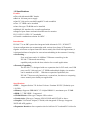
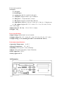
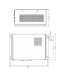
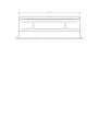
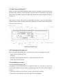
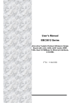
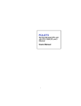
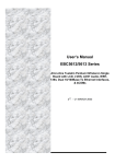
ES-200-77
Multimedia Pentium III processor-based computer for HMI Applications
User's Manual
Copyright Notice
Advantech Co., Ltd copyrights this document. All rights are reserved.
Advantech Co., Ltd. reserves the right to make improvements to the products
described in this manual at any time. Specifications are thus subject to change
without notice.
No part of this manual may be reproduced, copied, translated, or transmitted in
any form or by any means without the prior written permission of Advantech
Co., Ltd. Information provided in this manual is intended to be accurate and
reliable. However, Advantech Co., Ltd. assumes no responsibility for its use,
not for any infringements upon the rights of third parties that may result from its
use.
All brand and product names mentioned herein are trademarks or registered
trademarks of their respective holders.
FCC Class A
This equipment has been tested and found to comply with the limits for a Class
A digital device, pursuant to Part 15 of the FCC Rules. These limits are
designed to provide reasonable protection against harmful interference when
the equipment is operated in a commercial environment. This equipment
generates, uses and can radiate radio frequency energy. If not installed and
used in accordance with this user manual, it may cause harmful interference to
radio communications. Operation of this equipment in a residential area is
likely to cause harmful interference, in which case the user will be required to
correct the interference at his/ her own expense.
1st Edition Printed in Taiwan
Safety Instructions
1.
Read these safety instructions carefully.
2.
Keep this User’s Manual for later reference.
3.
Disconnect this equipment from any AC outlet before cleaning. Use a damp cloth. Do
not use liquid or spray detergents for cleaning.
4.
For plug-in equipment, the power outlet socket must be located near the equipment and
must be easily accessible.
5.
Keep this equipment away from humidity.
6.
Put this equipment on a reliable surface during installation. Dropping it or letting it fall
may cause damage.
7.
The openings on the enclosure are for air convection. Protect the equipment from
overheating. DO NOT COVER THE OPENINGS.
8.
Make sure the voltage of the power source is correct before connecting the equipment to
the power outlet.
9.
Position the power cord so that people cannot step on it. Do not place anything over the
power cord.
10.
All cautions and warnings on the equipment should be noted.
11.
If the equipment is not used for a long time, disconnect it from the power source to avoid
damage by transient over voltage.
12.
Never pour any liquid into an opening. This may cause fire or electrical shock.
13.
Never open the equipment. For safety reasons, the equipment should be opened only
by qualified service personnel.
14.
If one of the following situations arises, get the equipment checked by service personnel:
a. The power cord or plug is damaged.
b. Liquid has penetrated into the equipment.
c. The equipment has been exposed to moisture.
d. The equipment doesn’t work well, or you cannot get it to work according to the user’s
manual.
e. The equipment has been dropped and damaged.
f. The equipment has obvious signs of breakage.
15.
DO NOT LEAVE THIS EQUIPMENT IN AN UNCONTROLLED
ENVIRONMENT WHERE THE STORAGE TEMPERATURE IS BELOW -20C (-4F) OR
ABOVE 60C (140F). THIS MAY DAMAGE THE EQUIPMENT.
Packing List
Before installing your equipment, make sure that the following materials have been received:
•
ES-200-77
•
Accessory box, including:
-
CD kit for ES-200 Driver
-
2-wire Power cord for 1.8 Meters
-
30cm COM port cable
-
30cm VGA cable
-
30cm power cable for ES-3115/ES-3112/ES-3117 DC output
-
Wall mount bracket * 2 pcs.
-
Side mount for ES-3115/ES-3117 iron bracket * 4pcs.
-
Side mount for ES-3112 iron plate *2pcs
If any of these items are missing or damaged, contact your distributor or sales representative
immediately.
Additional Information and Assistance
1. Visit the Advantech web sites at www.advantech.com or www.advantech.com.tw
where you can find the latest information about the product.
2. Contact your distributor, sales representative, or Advantech's customer service
center for technical support if you need additional assistance. Please have the
following information ready before you call:
• Product name and serial number
• Description of your peripheral attachments
• Description of your software (operating system, version, application software, etc.)
• A complete description of the problem
• The exact wording of any error messages
Contents
Chapter 1 Introduction.................................................................................1
1.1
Introduction.............................................................................................2
1.2
How to use this menu.............................................................................3
1.3
Specification ...........................................................................................4
1.4
Dimensions.............................................................................................5
Chapter 2 System Setup..............................................................................9
2.1
Introduction...........................................................................................10
2.2
Quick Tour of ES-200-77......................................................................10
2.3
Preparing for the initial use ..................................................................10
2.4
Installation Procedure...........................................................................11
Chapter 3
3.1
Using ES-200-77....................................................................16
Introduction
3.2 Hard Drive
3.3 CD-ROM Drive
3.4 PS/2 Mouse and Keyboard
3.5 PCI Bus Expansion
3.6 Parallel Port
3.7 Serial COM Ports
3.8 VGA Port
3.9
Game Port
3.10
USB Ports
3.11
Audio Interface
3.12
Ethernet
Chapter 1
General Information
This chapter gives
information on ES-200-77
Sections
•
• How to Use
•
•
1.1 General Information
The ES-200-77 PC is a multimedia Pentium III processor-based computer that is designed to
serve as a human machine interface (HMI) and as a desktop computer. . You can select what
application or integration for your system then decide which part you want to apply, or, of
course, integrate both as a high performance panel PC.
As PC module, this system with on-board PCI Ethernet controller, multi-COM port interfaces
and a 16-bit stereo audio controller provides most of PC function. With built-in CD-ROM drive,
floppy drive and, ES-200-77 is as compact and user-friendly as a fully expansion computer.
For system integrators, complete, compact and highly integrated multimedia system speeds
up the product development lead time and provides versatile integration design and
application. It’s also perfectly for common industrial applications included factory automation
system, precision machinery, production process control and other application for
non-industrial applications, including interactive kiosk systems, entertainment management,
and car parking automation.
1.2 How to use this manual
This manual contains all the information you need to set up and use the panel PC. In addition
to this manual, you may also want to consult the manuals for your operating system, software
applications and peripherals. Whether you are a new or an experienced user, you will benefit
more from this manual if you are familiar with its organization. This manual is divided into four
chapters.
Chapter 1 (this chapter) outlines the organization of this User’s Manual, provides a complete
specification description of the ES-200-77, and summarizes its main features.
Chapter 2 provides step-by-step instructions to help you set up and begin using the panel PC
as quickly as possible.
Chapter 3 provides important information about the daily use of the panel PC, including using
the CD-ROM drive, floppy drive and enjoying the panel PC’s audio capabilities.
Chapter 4 provides a detailed description of jumper settings and connectors of the
motherboard of the ES-200-77.
If you are a commercial user and the panel PC unit you bought is a complete set
with CPU, hard disk drive, SDRAM, CD-ROM drive, floppy disk drive and PCMCIA
expansion slots included, you may only need to read Chapters 1 through 3
regarding hardware operation.
1.3 Specifications
Feature:
● Fits with Advantech SBC boards.
● Buit-in 180-watt power supply.
● One PC-104 card or one half-length PCI card extendible
● Two 3.5” HDD can be installed
● One slim-type CD-ROM can be installed
● Multiple I/O interfaces for versatile applications
● Support Open-frame mechanical architecture for monitor
ES-3112/ES-3115/ES-3117 attachable .
● Versatile combination solution for OFPC .
Introduction:
ES-200-77 is an SBC system box integrated with Advantech 5.25“, PCM-9577.
System configuration can accommodate with various Open-frame LCD monitor
together to become an Open framed PC that is mainly used for Kiosk applications; it
is designed without a faceplate for convenient embedding in the customer’s housing .
● Networking :
Four serial ports and a 10/100Base-T Ethernet controller give the
ES-200-77 advanced networking
capability and provide the best solution for versatile applications
● Extended Capability:
The ES-200-77 is designed with one expansion slot for PCI cards, two USB
ports, one PC-104 card, two 3.5” HDDs and multiple display size monitor
can be attached as OFPC. With these expansion capabilities, the
ES-200-77 does not only function as a system box, but also as a computing
center around you to build your application.
Specifications:
● CPU: Supports Socket 370 for Intel Celeron / Pentium III CPU (Tualatin) up to
1.26 GHz
● Memory: Supports SDRAM PC133 168pin DIMM *1, maximum up to 512MB
● HDD: 3.5” IDE HDD * 2 supported
● CD-ROM drive: Slim type Compact 24X or above
● Combo drive: Slim type Compact 24X/10X/24X and DVD 8X or above.
● Graphic: VIA Twister chipset (VT8606) with integrated S3 Savage 4 supports
2D/3D 4X AGP graphics
● Expansion Interface: One expansion slot for half-size PCI card and PC104 slot for
PC104 card expansion.
● I/O port:
- 1* VGA port
- 1* Parallel port
- 4 * serial ports: RS-232 3, RS-232/422/485*1
- 2 * USB ports: Support USB1.1 up to 20Mb/sec.
- 2 * PS2 ports: 1 * keyboard and 1* mouse
- 1 * RJ 45 port: Supports 10/100T-Base Ethernet
- 4 * Audio port: Supports 1* line in /1* line out / 1* Mic in / 1* Speaker out
- 1 * DC output: Supports DC 3.3V =16.8A, 5V = 12A, 12V=10A, 5V=2A,
-12V =0.8A output
● Dimensions (W * H * D): 353.6* 225.6 * 100mm
● Weight: 3.4Kg
Power Specifications:
● Input voltage: AC100-240V, 4-2A, 50-60 Hz
● Output voltage: DC 3.3V =16.8A, 5V = 12A, 12V=10A, 5V=2A, -12V =0.8A
● Output rating: 180W (including ES-200-77 and related DC device).
Environment Specifications:
● Operation Temperature: 0~45º C
● Storage Temperature: -20 ~ 60º C
● Humidity: 5-95% @40º C, non-condensing.
● Shock: 10G peak acceleration (11msec. Duration)
● EMC Approved: CE FCC
● Safety Approved: UL
‧
1.4 Dimension
Chapter 2
System Setup
Sections include:
• A Quick Tour of the Panel PC
• Preparing for initial Use
• Installation Procedures
• Installing the Drivers
2.1 Quick Tour for ES-200-77
Before you start to set up ES-200, please take a moment to be familiar with the locations and
purposes of the controls, drives, connectors and ports, which are illustrated in the figures
below. When you place the panel PC upright on the desktop, its front panel appears as shown
in Figure 2-1.
The sunken I/O section is at the bottom of the panel PC, as shown in Fig. 2-2. (The I/O section
includes various I/O ports, including serial ports, parallel port, the Ethernet port, USB ports, the
microphone jack, and so on.)
Figure 2-2:ES-200-77 I/O
2.2 Preparing for first-time use
Before you start to set up ES-200-77, you should have at least the following items ready:
‧ Power cord (in the accessory box)
‧ Keyboard
‧ Mouse (for system software installation, i.e. Microsoft Windows NT, etc.)
‧ Display (ES-3115 for optional)
2.3 Installation procedure
2.3.1 Connecting the power cord
The panel PC can only be powered by an AC electrical outlet (100 ~ 250 volts, 50 ~ 60 Hz). Be
sure to always handle the power cords by holding the plug ends only. Follow these procedures
in order:
1. Connect the female end of the power cord to the AC inlet of the panel PC.
2. Connect the 3-pin male plug of the power cord to an electrical outlet.
2.3.2 Connecting the keyboard and mouse
Connect the PS/2 mouse and keyboard port on the I/O section of the panel PC.
2.3.3 Connecting the display
Connect the display to the VGA sub in the bottom of ES-200-77
2.3.4 Switch on the power
Switch on the power switch on the rear cover.
2.4 Running the BIOS setup program
Your panel PC is likely to have been properly set up and configured by your dealer prior to
delivery. You may still find it necessary to use the panel PC's BIOS (Basic Input-Output
System) setup program to change system configuration information, such as the current date
and time or your type of hard drive. The setup program is stored in read-only memory (ROM).
It can be accessed either when you turn on or reset the panel PC, by pressing the "Del" key on
your keyboard immediately after powering on the computer.
The settings you specify with the setup program are recorded in a special area of memory
called CMOS RAM. This memory is backed up by a battery so that it will not be erased when
you turn off or reset the system. Whenever you turn on the power, the system reads the
settings stored in CMOS RAM and compares them to the equipment check conducted during
the power on self-test (POST). If an error occurs, an error message will be displayed on screen,
and you will be prompted to run the setup program.
2.5 Installing the system software
Recent releases of operating systems from major vendors include setup programs which load
automatically and guide you through hard disk preparation and operating system installation.
The guidelines below will help you determine the steps necessary to install your operating
system on the panel PC hard drive.
If required, insert your operating system's installation or setup diskette into the diskette drive
until the release button pops out. The BIOS of the panel PC supports system boot-up directly
from the CDROM drive. You may also insert your system installation CD-ROM into the
CD-ROM drive.
Power on your panel PC or reset the system by pressing the "Ctrl"+"Alt"+"Del" keys
simultaneously. The panel PC will automatically load the operating system from the diskette or
CD-ROM. If you are presented with the opening screen of a setup or installation program,
follow the instructions on screen. The setup program will guide you through preparation of your
hard drive, and installation of the operating system.
If you are presented with an operating system command prompt, such as A:\>, then you must
partition and format your hard drive, and manually copy the operating system files to it. Refer
to your operating system user's manual for instructions on partitioning and formatting a hard
drive.
2.6 Installing the drivers
After installing your system software, you will be able to set up the Ethernet, VGA, audio,
PCMCIA and touchscreen functions. All the drivers except the CD-ROM drive driver are stored
in a CD-ROM disc entitled "Drivers and Utilities." The CD-ROM drive driver is stored in a floppy
disk. Both the CD-ROM and the floppy disk can be found in your accessory box.
To set up the CD-ROM function, insert the floppy disk with the CD-ROM drive driver into the
floppy disk drive and type "install" after the following prompt is displayed on screen:
A: > INSTALL
Press "Enter", and the installation process will be completed in a few seconds.
The various drivers and utilities in the CD-ROM disc have their own text files which help users
install the drivers and understand their functions. These files are a very useful supplement to
the information in this manual.
Note: The drivers and utilities used for ES-200 are subject to change without notice.
If in doubt, check Advantech's website or contact our application engineers for the
latest information regarding drivers and utilities.
Chapter 3
Using the Panel PC
This chapter details installing ES-200 hardware.
Sections include:
• CD-ROM Drive
• PS/2 Mouse and Keyboard
• PCI/ISA Bus Expansion
• Parallel Port
• Serial COM Ports
• VGA Port
• USB Ports
• Audio Interface
• Ethernet
3.1 CD-ROM drive
To insert a CD-ROM disc, press the eject button of the CD-ROM drive. The yellow activity light
will flash and the front panel will come out a short distance. Using your fingertips, hold the top
and bottom of the front panel and pull it outward to the very end. Align the center hole of the
CD-ROM disc with the center circle of the CD-ROM holding plate. Press the transparent ring
around the center hole of the CD-ROM until you hear a click. Push the front panel of the
CD-ROM drive back to its original place.
To eject a CD-ROM disc, first ensure that the drive activity light is off. Then press the eject
button on the drive. When the disc pops out of the drive, remove it and store it properly.
3.2 PS/2mouse & keyboard
If you wish to use a full-size desktop keyboard and PS/2 mouse with your panel PC, follow
these instructions:
1. Be sure the panel PC is turned off.
2. Connect the PS/2 mouse and keyboard on the port on the rear bottom side of the rear cover.
3. Turn on the panel PC.
3.3 PCI Bus Expansion
The panel PC supports PCI bus expansion cards. To integrate a new PCI bus card into your
system, follow these instructions:
1. Turn off the panel PC.
2. Unscrew the 6 screws on the rear cover, and remove this cover.
3. Remove the metal plate by unscrewing the attaching screw.
4. Insert the PCI bus card into the PCI slot of the riser card.
5. Run the setup program within your operating system to configure your system.
3.4 Parallel port
The panel PC supports the latest EPP and ECP parallel port protocols for improved
performance and versatility with compatible printers or other devices.
To connect the panel PC to a printer or other devices:
1. Be sure both the panel PC and the printer/devices are turned off.
2. Connect the 25-pin male connector of the printer cable to the 25- pin female port on the
panel PC labeled "parallel port".
3. If necessary, attach the other end of your printer cable to your printer, and fasten any
retaining screws.
4. Turn on the printer and any other peripheral devices you may have connected to the panel
PC, and then turn on the panel PC.
5. If necessary, run the panel PC's BIOS setup program to configure the parallel port to
respond as required by your printer and software operating environment.
3.5 Serial COM ports
There are three serial COM ports on the bottom of the rear cover. You can easily attach a
serial device to the panel PC, such as an external modem or mouse. Follow these instructions:
1. Be sure the panel PC and any other peripheral devices you may have connected to the
panel PC are turned off.
2. Attach the interface cable of the serial device to the panel PC's serial port. If necessary,
attach the other end of the interface cable to your serial device. Fasten any retaining screws.
3. Turn on any other peripheral devices you may have connected to the panel PC, and then
turn on the panel PC.
4. Refer to the manual(s) which accompanied your serial device(s) for instructions on
configuring your operating environment to recognize the device(s).
5. Run the BIOS setup program and configure the jumper settings to change the mode of the
COM ports.
3.6 VGA port
An external VGA-compatible device may be connected to the system through the 15-pin
external port located on the rear of the system unit.
The panel PC simultaneously supports an external CRT monitor in addition
to its own LCD display.
1. Be sure the panel PC is turned off.
2. Connect the external monitor to the system.
3. Turn on the panel PC and the external monitor.
3.7 USB ports
An external USB device may be connected to the system through the 4-pin USB ports located
on the rear side of the system unit.
1. Connect the external device to the system.
2. The USB ports support hot plug-in connection. You should install the device driver before
you use the device.
3.8 Audio interface
The audio interface includes three jacks: microphone in, line out and line in.
Their functions are:
Microphone in: Use an external microphone to record voice and sound.
Line out: Output audio to external devices such as speakers or earphones.
Line in: Input audio from an external CD player or radio.
1. Connect the audio device to the system.
2. Install the driver before you use the device.
3.9 Ethernet
External devices on your network may be connected to the system through the external
Ethernet port located on the rear side of the system unit.
1. Be sure the panel PC is turned off.
2. Connect the external device(s) to the panel PC.
3. Turn on the panel PC and the external device(s).
4. Run the Ethernet driver to connect up to the network.