1
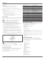
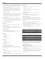
®
DW708
14
15
16
1
2
13
3
11A
4
12
11
10
5
9
6
8
7
A1
18
17
19
26
20
21
25
22
23
24
A2
16
28
10
B
27
C
29 31 30
2
33
7
32 33
D1
37 36 38
34 35
E
26
6
D2
F
40
39
34
5
4
37
4
42
36
41
G
H1
11
20
11
43
44
43A
12
45
H3
H2
7
11A
46
23
11
H4
J
19
20
K
L
1
47
20
4
5
M2
M1
23
11 49
3
N1
7
M3
N2
A
N3
N4
6
O
P1
21
P2
22
R
Q1
Q2
ENGLISH
Safety instructions
When using Power Tools, always observe the safety regulations
applicable in your country to reduce the risk of fire, electric shock
and personal injury. Read the following safety instructions before
attempting to operate this product.
Keep these instructions in a safe place!
General
1 Keep work area clean
Cluttered areas and benches can cause accidents.
2 Consider work area environment
Do not expose Power Tools to humidity.
Keep work area well lit.
Do not use Power Tools in the presence of inflammable liquids or gases.
3 Guard against electric shock
Prevent body contact with earthed surfaces (e.g. pipes, radiators,
cookers and refrigerators).
For use under extreme conditions (e.g. high humidity, when metal
swarf is being produced, etc.) electric safety can be improved by
inserting an isolating transformer or a (FI) earth-leakage circuit-breaker.
4 Keep children away
Do not let children come into contact with the tool or extension cord.
Supervision is required for those under 16 years of age.
5 Extension cords for outdoor use
When the tool is used outdoors, always use extension cords intended
for outdoor use and marked accordingly.
6 Store idle tools
When not in use, Power Tools must be stored in a dry place and
locked up securely, out of reach of children.
7 Dress properly
Do not wear loose clothing or jewellery. They can be caught in moving
parts. Preferably wear rubber gloves and non-slip footwear when working
outdoors. Wear protective hair covering to keep long hair out of the way.
8 Wear safety goggles
Also use a face or dust mask in case the operations produce dust or
flying particles.
9 Beware of maximum sound pressure
Take appropriate measures for the protection of hearing if the sound
pressure of 85 dB(A) is exceeded.
10 Secure workpiece
Use clamps or a vice to hold the workpiece. It is safer and it frees both
hands to operate the tool.
11 Do not overreach
Keep proper footing and balance at all times.
12 Avoid unintentional starting
Do not carry the plugged-in tool with a finger on the switch.
Be sure that the switch is released when plugging in.
13 Stay alert
Watch what you are doing. Use common sense.
Do not operate the tool when you are tired.
14 Disconnect tool
Shut off power and wait for the tool to come to a complete standstill
before leaving it unattended. Unplug the tool when not in use,
before servicing or changing accessories.
15 Remove adjusting keys and wrenches
Always check that adjusting keys and wrenches are removed from the
tool before operating the tool.
16 Use appropriate tool
The intended use is laid down in this instruction manual. Do not force
small tools or attachments to do the job of a heavy-duty tool. The tool
will do the job better and safer at the rate for which it was intended.
Warning! The use of any accessory or attachment or performance of
any operation with this tool, other than those recommended in this
instruction manual may present a risk of personal injury.
18
17 Do not abuse cord
Never carry the tool by its cord or pull it to disconnect from the socket.
Keep the cord away from heat, oil and sharp edges.
18 Maintain tools with care
Keep the tools in good condition and clean for better and safer
performance. Follow the instructions for maintenance and changing
accessories. Inspect the tool cords at regular intervals and,
if damaged, have them repaired by an authorized DEWALT repair
agent. Inspect the extension cords periodically and replace them if
damaged. Keep all controls dry, clean and free from oil and grease.
19 Check for damaged parts
Before using the tool, carefully check it for damage to ensure that it will
operate properly and perform its intended function. Check for
misalignment and seizure of moving parts, breakage of parts and any
other conditions that may affect its operation. Have damaged guards
or other defective parts repaired or replaced as instructed. Do not use
the tool if the switch is defective. Have the switch replaced by an
authorized DEWALT repair agent.
20 Have your tool repaired by an authorized DEWALT repair agent
This Power Tool is in accordance with the relevant safety regulations.
To avoid danger, electric appliances must only be repaired by qualified
technicians.
Additional safety rules for mitre saws
• Make sure that the blade rotates in the correct direction. Keep the
blade sharp. Do not use blades of larger or smaller diameter than
recommended. For the proper blade rating refer to the technical data.
• Make sure all locking knobs and clamp handles are tight before starting
any operation.
• Check periodically that the motor air slots are clean and free of chips.
• Disconnect the machine from the mains before carrying out any
maintenance work or when changing the blade.
• Before using any accessory consult the instruction manual.
The improper use of an accessory can cause damage.
• Allow the motor to reach full speed before cutting.
• Raise the blade from the kerf in the workpiece prior to releasing the switch.
• Do not wedge anything against the fan to hold the motor shaft.
• Never place either hand in the blade area when the saw is connected
to the electrical power source.
• Do not attempt to cut excessively small pieces.
• Never attempt to stop a machine in motion rapidly by jamming a tool or
other means against the blade; serious accidents can be caused
unintentionally in this way.
• Do not use cracked or damaged saw blades.
• Do not use any abrasive discs.
• Do not cut ferrous metals, non-ferrous metals or masonry.
• Never use your saw without the kerf plate.
• The blade guard on your saw will automatically raise when the arm is
brought down; it will lower over the blade when the arm is raised.
The guard can be raised by hand when installing or removing saw
blades or for inspection of the saw. Never raise the blade guard
manually unless the saw is turned OFF.
• The front section of the guard is louvred for visibility while cutting.
Although the louvres dramatically reduce flying debris, there are
openings in the guard and safety glasses should be worn at all times
when viewing through the louvres.
en - 2
ENGLISH
Residual risks
The following risks are inherent to the use of mitre saws:
- injuries caused by touching the rotating parts
In spite of the application of the relevant safety regulations and the
implementation of safety devices, certain residual risks cannot be avoided.
These are:
- Impairment of hearing.
- Risk of accidents caused by the uncovered parts of the rotating saw
blade.
- Risk of injury when changing the blade.
- Risk of squeezing fingers when opening the guards.
- Health hazards caused by breathing dust developed when sawing
wood, especially oak, beech and MDF.
Electrical safety
Conductor size (mm2)
Cable rating (Amperes)
0.75
1.00
1.50
2.50
4.00
6
10
15
20
25
Voltage
115
230
The electric motor has been designed for one voltage only. Always check
that the power supply corresponds to the voltage on the rating plate.
Your DEWALT tool is double insulated in accordance with
EN 50144; therefore no earth wire is required.
Mains plug replacement (U.K. & Ireland only)
• Should your mains plug need replacing and you are competent to do
this, proceed as instructed below. If you are in doubt, contact an
authorized DEWALT repair agent or a qualified electrician.
• Disconnect the plug from the supply.
• Cut off the plug and dispose of it safely; a plug with bared copper
conductors is dangerous if engaged in a live socket outlet.
• Only fit 13 Amperes BS1363A approved plugs fitted with the correctly
rated fuse (1).
• The cable wire colours, or a letter, will be marked at the connection
points of most good quality plugs. Attach the wires to their respective
points in the plug (see below). Brown is for Live (L) (2) and Blue is for
Neutral (N) (4).
• Before replacing the top cover of the mains plug ensure that the cable
restraint (3) is holding the outer sheath of the cable firmly and that the
two leads are correctly fixed at the terminal screws.
Amperes
0 - 2.0
2.1 - 3.4
3.5 - 5.0
5.1 - 7.0
7.1 - 12.0
12.1 - 20.0
0 - 2.0
2.1 - 3.4
3.5 - 5.0
5.1 - 7.0
7.1 - 12.0
12.1 - 20.0
Cable length (m)
7.5
15
25
30
Cable rating (Amperes)
6
6
6
6
6
6
6
6
6
6
10
15
10
10
15
20
15
15
20
25
20
20
25
6
6
6
6
6
6
6
6
6
6
6
6
10
10
10
10
15
15
15
15
20
20
20
20
45
60
6
15
20
20
25
6
6
10
15
20
25
10
15
20
25
6
6
15
15
20
-
Unpacking (fig. A1, A2 & B)
Remove the saw from the packing material carefully using the carrying
handle (9) and the rails (14). The package contains:
1 Assembled sliding compound mitre saw
1 Saw blade wrench
1 60 teeth 305 mm TCT saw blade
1 Stabilizer
1 Instruction manual
1 Exploded drawing
• Check for damage to the tool, parts or accessories which may have
occurred during transport.
• Take the time to thoroughly read and understand this manual prior to
operation.
• Press down the operating handle (17) and pull out the lock down pin (16),
as shown in fig. B.
• Gently release the downward pressure and allow the arm to rise to its
full height.
Description (fig. A1 & A2)
Your DW708 sliding compound mitre saw has been designed for
professional cutting of wood, wood products, aluminium and plastics.
It will perform the sawing operations of cross-cutting, bevelling and mitring
easily, accurately and safely.
A1
Never use a light socket. Never connect the live (L) or neutral
(N) wires to the earth pin marked E or .
For 115 V units with a power rating exceeding 1500 W, we recommend to
fit a plug to BS4343 standard.
Using an extension cable
If an extension cable is required, use an approved extension cable suitable
for the power input of this tool (see technical data). The minimum
conductor size is 1.5 mm2.
When using a cable reel, always unwind the cable completely.
Also refer to the table below.
en - 3
1
2
3
4
5
6
7
8
9
10
11
11A
12
13
14
15
16
ON/OFF-switch
Lower blade guard
Fence, right-hand side
Mitre lever
Mitre latch
Mitre scale
Fence, left-hand side
Bench mounting holes
Base
Base stabiliser
Bevel lever
Bevel stop override button
Bevel stop screw
Saw blade wrench
Rails
Dust extraction adapter
Lock down pin
19
ENGLISH
A2
17
18
19
20
21
22
23
24
25
26
Operating handle
Carrying handle
Rail adjustment screws
Rail lock knob
Thumbscrew
Grooving stop
Fence adjustment knob
Handhold
Kerf plate
Spindle lock button
To use the spindle lock, press the button as shown and rotate
the spindle by hand until you feel the lock engage. Continue to
hold the lock button in to keep the spindle from turning (fig. D2).
• Remove the blade screw (31) and the outer flange (32) (fig. D1).
• Install the saw blade (33) onto the inner flange making sure that the
teeth at the bottom edge of the blade are pointing toward the back of
the saw (away from the operator).
• Replace the outer flange (32).
• Tighten the blade locking screw (31) by turning counter-clockwise while
holding the lower guard up and the spindle lock engaged with your
other hand.
Assembly
Never press the spindle lock while the blade is rotating.
Prior to assembly always unplug the tool.
Adjustment
The motor and guards are already assembled onto the base.
Stabilizer (fig. C)
Your saw includes one base stabilizer (10).
• Insert the stabilizer into the holes (27).
• Move the stabilizer in or out until it contacts the work surface.
• Tighten the screws (28).
Never use your saw without the stabilizer.
Bench mounting (fig. A2)
• Holes (8) are provided in all four feet to facilitate bench mounting.
Two different sized holes are provided to accommodate different sizes
of bolts. Use either hole; it is not necessary to use both. Always mount
your saw firmly to prevent movement. To enhance the portability,
the tool can be mounted to a piece of 12.5 mm or thicker plywood
which can then be clamped to your work support or moved to other
job sites and reclamped.
• When mounting your saw to a piece of plywood, make sure that the
mounting screws do not protrude from the bottom of the wood.
The plywood must sit flush on the work support. When clamping the
saw to any work surface, clamp only on the clamping bosses where
the mounting screw holes are located. Clamping at any other point will
interfere with the proper operation of the saw.
• To prevent binding and inaccuracy, be sure the mounting surface is not
warped or otherwise uneven. If the saw rocks on the surface, place a
thin piece of material under one saw foot until the saw is firm on the
mounting surface.
Mounting the saw blade (fig. A1, A2, D1 & D2)
The teeth of a new blade are very sharp and can be
dangerous.
Lock the mitre lever (4), the rail lock knob (20) and the bevel
lever (11) (fig. A1 & A2).
• Depress the head lock up release lever (50) to release the lower guard
(2), then raise the lower guard as far as possible.
• Loosen the upper guard cover screw (29) and pivot the upper guard (30) up.
Never replace the screw (29) with a different screw!
• Hold the guard up, press the spindle lock button (26) (fig. D2) and
loosen the blade screw (31) by turning clockwise using the saw blade
wrench (fig. D1).
20
Prior to adjustment always unplug the tool.
Your mitre saw was accurately adjusted at the factory. If readjustment due
to shipping and handling or any other reason is required, follow the steps
below to adjust your saw. Once made, these adjustments should remain
accurate.
Checking and adjusting the blade to the fence (fig. E)
• Loosen the mitre lever (4) and squeeze the mitre latch (5) upwards to
release the scale/mitre arm assembly (34).
• Swing the mitre arm until the latch locates it at the 0° mitre position.
Do not tighten the lever (4).
• Pull down the head until the blade just enters the saw kerf (35).
• Place a square (36) against the lower part (37) of the fence (7) and
blade (33).
Do not touch the tips of the blade teeth with the square.
If adjustment is required, proceed as follows:
• Loosen the four screws (38) and move the scale/mitre arm assembly (34)
left or right until the blade is at 90° to the fence as measured with
the square.
• Retighten the four screws (38). Pay no attention to the reading of the
mitre pointer at this point.
Adjusting the mitre pointer (fig. F)
• Loosen the mitre lever and squeeze the mitre latch to release the
scale/mitre arm assembly (34).
• Move the saw arm to set the mitre pointer (39) to the zero position.
• With the mitre clamp knob loose, allow the mitre latch to snap into
place as you rotate the mitre arm past zero.
• Observe the pointer (39) and mitre scale (6). If the pointer does not
indicate exactly zero, loosen the screw (40) and gently move the
pointer left or right.
• Retighten the screw (40).
Mitre lock/detent rod adjustment (fig. G)
If the base of the saw can be moved while the mitre lever (4) is locked,
the mitre lock/detent rod (41) should be adjusted.
• Unlock the mitre lever (4).
• Fully tighten the mitre lock/detent rod (41) by turning it clockwise using
a screwdriver (42). Turn counterclockwise 1/4 of a turn.
• Check that the table will not rotate when the lever (4) is locked at a
random (not preset) angle.
en - 4
ENGLISH
Bevel stop adjustment (fig. H1 - H4)
Adjusting the bevel stop and pointer to 0° (fig. H1 & H2)
• Place the saw in the 0° bevel position (fig. H1).
• Push the head fully back and tighten the rail lock knob (20) (fig. H2).
• Place a set square (36) on the table and up against the blade (33) (fig. H1).
Do not touch the tips of the blade teeth with the square.
If adjustment is required, proceed as follows:
• Loosen the bevel lever (11) (fig. H2).
• Press the mitre arm to the right, against the 0° bevel stop.
• Adjust the screw (43) until the blade is perpendicular to the base.
• Tighten the lever (11) securely.
• Make sure the bevel pointer (44) indicates exactly 0°.
• If not, loosen the screw (45), set the pointer to 0° and tighten the screw.
Adjusting the bevel stop to 45° left or right (fig. H2 - H4)
First, adjust the 0° bevel angle.
- Left 45° bevel angle
• Loosen the bevel lever (11) and tilt the head to the left (fig. H3).
• If the pointer (44) does not indicate exactly 45°, turn the screw (12)
on the left side until the pointer reads 45° (fig. H2).
- Right 45° bevel angle
• Depress the bevel stop override button (11A) and tilt the head to the
right (fig. H4).
• If the pointer does not indicate exactly 45°, turn the screw (43A) on
the lower right side until the pointer reads 45° (fig. H3).
Adjusting the fence (fig. A1 & J)
The fences (3) and (7) can be adjusted to provide clearance, allowing the
saw to bevel to a full 48°.
• Loosen the fence adjustment knob (23) and slide the fence to the
required position (fig. J).
• Make a dry run with the saw turned OFF and check for clearance.
Adjust the fence to be as close to the blade as practical to provide
maximum workpiece support, without interfering with the up and down
movement of the arm.
• Firmly tighten the fence adjustment knob (23).
• Move the fences back after the cut has been accomplished.
When bevelling to the right, it may be necessary to remove the
right fence (3) (fig. A1)
Rail guide adjustment (fig. K)
• Regularly check the rails for clearance.
• To reduce clearance, gradually rotate the set screws (19) clockwise
while sliding the saw head back and forth.
Instructions for use
Always observe the safety instructions and applicable regulations.
The attention of UK users is drawn to the “woodworking
machines regulations 1974” and any subsequent amendments.
Prior to operation:
• Make sure the guards have been mounted correctly. The saw blade
guard must be in closed position.
• Make sure the saw blade rotates in the direction of the arrow on the blade.
• To stop the tool, release the switch.
• There is no provision for locking the switch ON, but a hole (47) is
provided for insertion of a padlock to lock the saw OFF.
Basic saw cuts (fig. A1, A2, M1 - M3)
Vertical straight cross cut (fig. A1 & A2)
• Loosen the mitre lever (4) and squeeze the mitre latch (5) upwards.
• Engage the mitre latch at the 0° position and tighten the lever (4).
• Place the wood to be cut against the fences (3) and (7).
• Take hold of the operating handle and depress the head lock up
release lever (50) to release the head.
• With the rail lock knob tightened, switch the saw ON.
• Lower the head to allow the blade to cut through the workpiece and
enter the kerf plate (25).
• After completing the cut, release the switch, let the blade come to a full
stop and return the head to its upper rest position.
Workpieces larger than 50 x 100 mm (fig. M1)
The guide rail allows cutting larger workpieces using an out-down-back motion.
• Release the rail lock knob (20).
• Pull the saw towards you, lower the saw into the workpiece and push it
back to complete the cut.
• Proceed as described above.
Vertical mitre cross-cut (fig. M2)
• Loosen the fence clamping knobs and adjust the fences.
• Loosen the mitre lever (4) and squeeze the mitre latch (5) upwards.
Move the head left or right to the required angle.
• Always ensure that the lever (4) is locked tightly before cutting.
• Proceed as for a vertical straight cross-cut.
Bevel cuts (fig. M3, H2 & H4)
• Loosen the fence clamping knobs (23) and adjust the fences (3) and (7).
Loosen the bevel lever (11) and set the required angle.
• Tighten the lever (11) firmly.
• To bevel to the right, depress the bevel stop override button (11A).
Bevelling 48° to the left (fig. H2 & H3)
To set a bevel angle greater than 45°, the bevel stop must be adjusted.
• Loosen the bevel lever (11) and tilt the head to the left.
• Turn the screw (12) until the pointer (44) indicates the desired bevel
angle (up to 48°).
Bevelling 48° to the right (fig. H2 - H4)
To set a bevel angle greater than 45°, the bevel stop must be adjusted.
• Depress the bevel stop override button (11A) and tilt the head to the
right.
• Turn the screw (43A) until the pointer (44) indicates the desired bevel
angle (up to 48°).
Quality of cut
The smoothness of any cut depends on a number of variables, e.g. the
material being cut. When smoothest cuts are desired for moulding and
other precision work, a sharp (60 tooth carbide) blade and a slower,
even cutting rate will produce the desired results.
Ensure that the material does not creep while cutting; clamp it
securely in place. Always let the blade come to a full stop
before raising the arm. If small fibres of wood still split out at
the rear of the workpiece, stick a piece of masking tape on the
wood where the cut will be made. Saw through the tape and
carefully remove tape when finished.
Switching ON and OFF (fig. L)
• To run the tool, press the ON/OFF-switch (1).
en - 5
21
ENGLISH
If the cutting angle varies from cut to cut, check that the bevel
and mitre levers are securely tightened.
• The chart shown below will assist you in selecting the proper bevel and
mitre settings for common compound mitre cuts. To use the chart,
select the desired angle “A” (fig. N4) of your project and locate that
angle on the appropriate arc in the chart. From that point follow the
chart straight down to find the correct bevel angle and straight across
to find the correct mitre angle.
• Set your saw to the prescribed angles and make a few trial cuts.
• Practice fitting the cut pieces together.
• Example: To make a 4 sided box with 25° exterior angles (angle “A”)
(fig. N4), use the upper right arc. Find 25° on the arc scale. Follow the
horizontal intersecting line to either side to get the mitre angle setting
on the saw (23°). Likewise follow the vertical intersecting line to the top
or bottom to get the bevel angle setting on the saw (40°). Always try
cuts on a few scrap pieces of wood to verify the settings on the saw.
0
5
10
80
85
45
15
25
30
35
40
45
SQUARE BOX
65
40
Trim moulding and other frames
Try a few simple projects using scrap wood until you develop a “feel” for
your saw. Your saw is the perfect tool for mitring corners like the one shown
in fig. N1. The joint shown has been made using either bevel adjustment.
50
45
40
6 SIDED BOX
75
65
30
Using mitre adjustment
The same cut can be made by mitring right and left with the broad surface
against the fence.
The two sketches (fig. N1 & N2) are for four side objects only. As the
number of sides changes, so do the mitre and bevel angles. The chart
below gives the proper angles for a variety of shapes, assuming that all
sides are of equal length. For a shape that is not shown in the chart, divide
180° by the number of sides to determine the mitre or bevel angle.
No. of sides
4
5
6
7
8
9
10
22
Angle mitre or bevel
45°
36°
30°
25.7°
22.5°
20°
18°
25
50
25
45
20
20
40
55
60
70
75
20
80
85
55
60
25
35
50
45
15
15
30
40
15
25
35
30
10
8 SIDED BOX
10
15
20
15
5
10
20
25
10
5
5
10
5
5
Using bevel adjustment
The bevel for the two boards is adjusted to 45° each, producing a 90°
corner. The mitre arm is locked in the zero position. The wood is
positioned with the broad flat side against the table and the narrow edge
against the fence.
30
35
70
80
85
30
65
Cutting picture frames, shadow boxes & other four sided projects
(fig. N1 - N4)
35
35
ANGLE OF SIDE OF BOX (ANGLE"A")
Support for long workpieces
• Always support long workpieces.
• For best results, use the extension work support (DE7080) to extend
the table width of your saw (available from your dealer as an option).
Support long workpieces using any convenient means such as sawhorses or similar devices to keep the ends from dropping.
SET THIS MITER ANGLE ON SAW
55
60
40
Always use a clamp when cutting small workpieces.
20
70
Clamping the workpiece (fig. M3)
Always use a material clamp when cutting non-ferrous metals.
• Whenever possible, clamp the workpiece to the saw.
• For best results use the clamp (49) (DE7082) made for use with your
saw (available from your dealer as an option). Clamp the workpiece to
the fence. You can clamp to either side of the saw blade; remember to
position your clamp against a solid, flat surface of the fence.
Compound mitre (fig. N3 & N4)
A compound mitre is a cut made using a mitre angle and a bevel angle at
the same time. This is the type of cut used to make frames or boxes with
slanting sides like the one shown in fig. N3.
75
Body and hand position
Proper positioning of your body and hands when operating the mitre saw
will make cutting easier, more accurate and safer.
• Never place your hands near the cutting area.
• Place your hands no closer than 150 mm from the blade.
• Hold the workpiece tightly to the table and the fence when cutting.
Keep your hands in position until the switch has been released and the
blade has completely stopped.
• Always make dry runs (without power) before finish cuts so that you
can check the path of the blade.
• Do not cross your hands.
• Keep both feet firmly on the floor and maintain proper balance.
• As you move the saw arm left and right, follow it and stand slightly to
the side of the saw blade.
• Sight through the guard louvres when following a pencil line.
0
5
10
15
20
25
30
35
40
45
SET THIS BEVEL ANGLE ON SAW
Dual range mitre scale (fig. O)
The mitre scale has two ranges of numbers for convenience, as shown in
fig. O. One scale indicates 0° when the blade is square to the fence.
At this position the other scale reads 90°. The 0° scale (larger numbers
closer to the front edge) is used when calculating angles. To calculate the
proper mitre angle, divide 180° by the number of sides of the box or
frame. Refer to the previous chart for some examples. The 90° scale
(smaller numbers behind the 0° scale) is used when a corner of your box
or frame is measured with a protractor. For example, if you measure the
corner of an 8 sided box, the protractor will read 135°. To determine the
proper mitre setting, divide the measured angle by two. The proper mitre
setting in this example is 671/2. Set this angle on the 90° scale.
Vernier scale (fig. P1 - P3)
Your saw is equipped with a vernier scale for added precision. For settings
that require partial degrees (1/4°, 1/2°, 3/4°), the vernier scale allows you to
accurately set mitre angles to the nearest 1/2° (15 minutes). To use the
vernier scale follow the steps listed below.
As an example, assume that the angle you want to mitre is 241/2° right.
• Turn OFF the mitre saw.
en - 6
ENGLISH
• Set the mitre angle to the nearest whole degree desired by aligning the
centre mark in the vernier scale, shown in (fig. P1), with the whole
degree number etched in the mitre scale. Examine (fig. P1) closely;
the setting shown is 24° right mitre.
• To set the additional 1/2°, squeeze the mitre arm lock and carefully
move the arm to the right until the 1/2° vernier mark aligns with the
closest degree mark on the mitre scale. In this example, the closest
degree mark on the mitre scale happens to be 25°. Fig. P2 shows a
setting of 241/2° right mitre.
When mitring to the right:
- increase the mitre angle by moving the arm to align the appropriate
vernier mark with the closest mark on the mitre scale to the right.
- decrease the mitre angle by moving the arm to align the appropriate
vernier mark with the closest mark on the mitre scale to the left.
When mitring to the left:
- increase the mitre angle by moving the arm to align the appropriate
vernier mark with the closest mark on the mitre scale to the left.
- decrease the mitre angle by moving the arm to align the appropriate
vernier mark with the closest mark on the mitre scale to the right.
Cutting base mouldings (fig. Q1 - Q4)
Vertical position
• Always make a dry run without power before making any cuts.
Outside corner
- Left side
• Position the moulding with the bottom of the moulding against
the fence.
• Save the right side of the cut.
- Right side
• Position the moulding with top of the moulding against the fence.
• Save the right side of the cut.
Grooving (fig. R)
Your saw is equipped with a grooving stop (22) and thumbscrew (21) to
allow for groove cutting.
• Flip the grooving stop (22) towards the front of the saw.
• Adjust the thumbscrew (21) to set the depth of the groove cut.
Cutting non-ferrous metals
When cutting non-ferrous metals, the machine is only to be used to
perform vertical straight and mitre cross-cuts in the mitre saw mode.
We recommend that bevel and compound mitre cuts should not be
performed in non-ferrous metals. The machine is not to be used for cutting
ferrous metals.
• Always use a material clamp when cutting non-ferrous metals.
Make sure that the workpiece is clamped securely.
• Only apply saw blades that are qualified for cutting non-ferrous metals.
• When using lubricants, only apply wax or separation spray. Do not use
emulsions or similar fluids.
• Connect an FI or DI switch between machine and mains to avoid
residual risks caused by metal swarf.
Straight 90° cuts (fig. Q1)
• Position the wood against the fence as shown in fig. Q1.
• Turn the saw ON, allow the blade to reach full speed and lower the arm
smoothly through the cut.
The FI switch should comply with the following specifications:
45° mitre cuts (fig. Q2)
• Position the moulding as shown in fig. Q2.
• All cuts are made with the back of the moulding against the fence and
the bottom of the moulding against the base.
rated voltage
rated current
reaction time
fusing current
Inside corner
- Left side
• Mitre left 45°.
• Save the left side of the cut.
- Right side
• Mitre right 45°.
• Save the right side of the cut.
The DI switch should comply with the following specifications:
Outside corner
- Left side
• Mitre right 45°.
• Save the left side of the cut.
- Right side
• Mitre left 45°.
• Save the right side of the cut.
DIN VDE 0661
rated voltage
rated current
fusing current
all-pole cutoff
PE monitoring
low-voltage release
230 V
16 A
< 15 ms
30 mA
230 V
16 A
30 mA
L+N+PE
Consult your dealer for further information on the appropriate accessories.
These include various saw blades, extension kits (DE7080), adjustable
length stops (DE7051), vertical clamps (DE7082), crown stops (DE7084)
and dustbags (DE7053).
Transport (fig. A1, A2 & B)
Horizontal position using bevel (fig. M3)
Another method of making the cut is to make a 0° mitre, 45° bevel cut.
All cuts are made with the back of the moulding laying flat on the saw as
shown in fig. M3.
Inside corner
- Left side
• Position the moulding with top of the moulding against the fence.
• Save the left side of the cut.
- Right side
• Position the moulding with the bottom of the moulding against the fence.
• Save the left side of the cut.
en - 7
In order to conveniently carry your saw, a carrying handle (9) has been
included on the top of the saw arm (fig. B).
• To transport the saw (fig. B), lower the arm and depress the lock down
pin (16) (fig. A1).
• Mitre the saw 60° to the right, lock the mitre lever (4), lock the rail lock
knob (20) with the head fully forward, slide the fences (7) completely
inward and lock the bevel lever (11) with the saw at 0° bevel.
• Always use the carrying handle (18) and/or the handholds (24) (fig. A2)
to transport the saw.
23
ENGLISH
Maintenance
Your DEWALT Power Tool has been designed to operate over a long
period of time with a minimum of maintenance. Continuous satisfactory
operation depends upon proper tool care and regular cleaning.
Lubrication
Your Power Tool requires no additional lubrication.
Cleaning
Keep the ventilation slots clear and regularly clean the housing with
a soft cloth.
GUARANTEE
• 30 DAY NO RISK SATISFACTION GUARANTEE •
If you are not completely satisfied with the performance of your
DEWALT tool, simply return it within 30 days, complete as purchased,
to a participating Dealer, or an authorized DEWALT repair agent,
for a full refund or exchange. Proof of purchase must be produced.
• ONE YEAR FREE SERVICE CONTRACT •
If you need maintenance or service for your DEWALT tool, in the
12 months following purchase, it will be undertaken free of charge at
an authorized DEWALT repair agent. Proof of purchase must be
produced. Includes labour and spare parts for Power Tools.
Excludes accessories.
• ONE YEAR FULL WARRANTY •
Unwanted tools and the environment
Take your tool to an authorized DEWALT repair agent where it will be
disposed of in an environmentally safe way.
If your DEWALT product becomes defective due to faulty materials or
workmanship within 12 months from the date of purchase,
we guarantee to replace all defective parts free of charge or,
at our discretion, replace the unit free of charge provided that:
• The product has not been misused.
• Repairs have not been attempted by unauthorized persons.
• Proof of purchase date is produced.
This guarantee is offered as an extra benefit and is additional to
consumers statutory rights.
For the location of your nearest authorized DEWALT repair agent,
please use the appropriate telephone number on the back of this
manual.
24
en - 8