1
YS
ROTARY SCREW LIQUID CHILLER
INSTALLATION, COMMISSIONING,
OPERATION AND MAINTENANCE
IRED
U
Q
E
R
E
R
U
T
IC
P
YS
STYLE: D
REFRIGERANT: R134a
Effective from 02/00
GB
035L02381-GB0
I- i
Table of Contents
1
2
SUPPLIER INFORMATION
3
1.1 Introduction
1.1
1.2 Warranty
1.1
1.3 Safety
1.1
1.4 Responsibility for Safety
1.1
1.5 About this Manual
1.2
1.6 Misuse of Equipment
1.2
1.7
Safety Labels
1.3
1.8 Material Safety Data
1.4
Product Description
2.1 General
2.1
2.2 Capacity Control
2.2
2.3 Compressor
2.3
2.4 Compressor Lubrication System
2.3
2.4.1
Oil Pump
2.4.2
Oil Heater
2.5 Compress Motor
2.5
2.6 Graphic Control Centre
2.5
2.7 Heat Exchangers
2.6
4
TRANSPORTATION, RIGGING AND
STORAGE
3.1 General
3.1
3.2 Shipment
3.1
3.3 Inspection, Damage and Shortage
3.2
3.4 Rigging
3.3
INSTALLATION
4.1 Location
4.1
4.2 Motors
4.1
4.3 Foundation
4.1
4.4 Clearances
4.1
4.5 Rigging Unit to Final Location
4.1
4.6 Locating and Installing Isolator Pads
4.1
4.7 Installing Optional Spring Isolators
4.2
4.8 Piping Connections
4.2
4.9 Cooler and Condenser Water Piping
4.2
4.9.1
Condenser Water Circuit
4.10 Stop Valves
4.6
4.11 Flow Switches (Field Installed)
4.6
4.12 Drain and Vent Valves
4.6
2.7.1
Evaporator
2.7.2
Condenser
4.13 Checking Piping Circuits and Venting Air
4.6
2.7.3
Water Boxes
4.14 Refrigerant Relief Piping
4.6
2.8 Refrigerant Flow Control
2.6
4.15 Unit Piping
4.6
2.9 Options and Accessories
2.7
4.16 Control Panel Positioning
4.7
2.9.1
Service Isolation Valves
4.17 Control Wiring
4.7
2.9.2
Hot Gas Bypass
4.18 Power Wiring
4.7
2.9.3
Solid State Starter
2.9.4
Variable Speed Drive
4.19 Units with Solid State Starter
or Variable Speed Drive
4.8
2.10 Nomenclature
2.8
4.20 Thermal Insulation
4.8
2.11 Range of Models
2.8
4.21 Installation Check
4.8
I-ii
5
5.1
6
035L02381-GB0
7.4
COMMISSIONING
Preparation
5.1
OPERATION
6.1
Oil Heater Operation
6.2
Checking the Oil Level in the Oil Reservoir 6.1
6.3
Start-up Procedure
6.4
6.3.1
Pre-Starting
6.3.2
Start-up
Chiller Operation
6.4.1
6.1
6.4
Condenser Water Temperature Control
6.5
Operating Log Sheet
6.4
6.6
Maintenance and Service
6.4
6.6.1
Normal and Safety System Shutdowns
6.6.2
Safety Shutdowns
6.6.3
Cycling Shutdowns
6.7
Stopping the System
6.6
6.8
Prolonged Shutdown
6.6
6.9
Start-up after Prolonged Shutdown
6.6
7
7.1
7.2
7.4.1
Checking The Refrigerant Charge
7.4.2
Leak Testing
7.4.3
Vacuum Testing
7.4.4
Refrigerant Charging
Condenser and Cooler
7.5.1
Chemical Water Treatment
7.5.2
Tube Cleaning
7.5.3
Tube Cleaning Procedures
7.5.4
Tube Leaks
7.3
7.5
7.6
Compressor
7.7
7.7
Compressor Motor
7.7
7.7.1
Greased Bearings on Reliance Q5800 Motors
7.8
Electrical Controls
7.8
7.9
Testing Motor Winding Insulation
7.8
8
TROUBLE SHOOTING
9
TECHNICAL DATA
9.1
Dimensions
9.1
9.2
Weights
9.4
9.3
Compressor Dimensions
9.6
9.4
Motor Weights
9.6
9.5
Optional Solid State Starter Details
9.6
9.6
Process and Instrumentation Diagram
9.7
Water Box Nozzle Arrangements
9.8
MAINTENANCE
Inspections
7.1
7.1.1
Daily
7.1.2
Weekly
7.1.3
Every 3 Months
7.1.4
Every 6 Months (or more often as required)
9.7
7.1.5
Annually (more often if necessary)
10
SPARE PARTS
7.2
11
DE-COMMISSIONING, DISMANTLING AND
DISPOSAL
7.2
11.1
Oil Return System
7.2.1
7.3
7.5
6.1
Refrigerant Charge
Changing the Dehydrator
Oil Charge
7.3.1
Oil Charging Procedure
General
11.1
035L02381-GB0
1
SUPPLIER INFORMATION
1.1
Introduction
York YS chillers are manufactured to the highest design
a nd construction standards to ensu r e hi gh
performance, reliability and adaptability to all types of air
conditioning installations.
The units are intended for cooling water or glycol
solutions and are not suitable for purposes other than
those specified in this manual.
This manual and the Control System Operating
Instructions contain all the information required for
correct installation and commissioning of the unit,
together with operating and maintenance instructions.
The manuals should be read thoroughly before
attempting to operate or service the unit.
All procedures detailed in the manuals, including
installation, commissioning and maintenance tasks
must only be performed by suitably trained and qualified
personnel.
The manufacturer will not be liable for any injury or
d amage caused by incorrect insta l l at i on,
commissioning, operation or maintenance resulting
from a failure to follow the procedures and instructions
detailed in the manuals.
1.2
Warranty
York International warrants all equipment and materials
against defects in workmanship and materials for one
year from initial start-up, or eighteen months from
delivery (whichever occurs first) unless extended
warranty has been agreed as part of the contract.
The warranty is limited to free replacement and shipping
of any faulty part, or sub-assembly which has failed due
to poor quality or manufacturing errors. All claims must
be supported by evidence that the failure has occurred
within the warranty period, and that the unit has been
operated within the designed parameters specified.
All warranty claims must specify the unit model, serial
number and order number.
The unit warranty will be void if any modification to the
unit is carried out without prior written approval from
York International.
1- 1
For warranty purposes, the following conditions must be
satisfied:
The initial start of the unit must be carried out by trained
personnel from an Authorised York Service Centre.
Only genuine York approved spare parts, oils and
refrigerants must be used.
All the scheduled maintenance operations detailed in
this manual must be performed at the specified times by
suitably trained and qualified personnel.
Failure to satisfy any of these conditions will
automatically void the warranty.
1.3
Safety
Standards for Safety
YS chillers are designed and built within an
EN ISO 9001 accredited design and manufacturing
organisation and, within the limits specified in this
manual, are in conformity with the essential health and
safety requirements of the following European Union
Directives:
Machinery Directive (89/392/EEC)
Low Voltage Directive (73/23/EEC, EN 60204)
EMC Directive (89/336/EEC)
1.4
Responsibility for Safety
Every care has been taken in the design and
manufacture of the units to ensure that they meet the
safety requirements listed in the previous paragraph.
However, the individual operating or working on any
machinery is primarily responsible for:
Personal safety, safety of other personnel, and the
machinery.
Correct utilisation of the machinery in accordance with
the procedures detailed in the manuals.
1- 2
1.5
035L02381-GB0
About this Manual
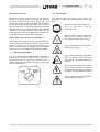
The following symbols are used in this document to alert
the reader to areas of potential hazard.
A Warning is given in this document to
identify a hazard which could lead to
personal injury. Usually an instruction will
be given, together with a brief explanation
and the possible result of ignoring the
instruction.
A Caution identifies a hazard which could
lead to damage to the machine, damage to
other equipment and/or environmental
pollution. Usually an instruction will be given,
together with a brief explanation and the
possible result of ignoring the instruction.
A Note is used to highlight additional
information which may be helpful to you but
w here there are no special saf et y
implications.
The contents of this manual include suggested best
working practices and procedures. These are issued for
guidance only, they do not take precedence over the
above stated individual responsibility and/or local safety
regulations.
This manual and any other document supplied with the
unit, are the property of York which reserves all rights.
They may not be reproduced, in whole or in part, without
prior written authorisation from an Authorised York
representative.
1.6
Misuse of Equipment
Suitability for Application
Structural Support
Structural support of the unit must be provided as
indicated in these instructions. Failure to provide proper
support may result in injury to the operator, or damage to
the equipment.
Mechanical Strength
The unit is not designed to withstand loads or stresses
from adjacent equipment, pipework or structures.
Additional components must not be mounted on the
unit. Any such extraneous loads may cause structural
failure and may result in injury to the operator, or
damage to the equipment.
General Access
There are a number of areas and features which may be
a hazard and potentially cause injury when working with
the unit unless suitable safety precautions are taken. It
is important to ensure access to the unit is restricted to
suitably qualified persons who are familiar with the
potential hazards and precautions necessary for safe
operation and maintenance of equipment containing
high temperatures, pressures and voltages.
Pressure Systems
The unit contains refrigerant vapour and liquid under
pressure, release of which can be a danger and cause
injury. The user should ensure that care is taken during
installation, operation and maintenance to avoid
damage to the pressure system. No attempt should be
made to gain access to the component parts of the
pressure system other than by suitably trained and
qualified personnel.
Electrical
The unit is intended for cooling water or glycol solutions
and is not suitable for purposes other than those
specified in these instructions. Any use of the equipment
other than its intended use, or operation of the
equipment contrary to the relevant procedures may
result in injury to the operator, or damage to the
equipment.
The unit must be earthed. No installation or
maintenance work should be attempted on electrical
equipment without first switching off, isolating and
locking-off the power supplies. Work on live equipment
must only be carried-out by suitably trained and
qualified personnel. No attempt should be made to gain
access to inside of the control panel, wiring or other
electrical enclosures during normal operation of the unit.
The unit must not be operated outside the design limits
specified in this manual.
Rotating Parts
Motor air vent guards and drive coupling guards must be
fitted at all times and not removed unless the main
power supply has been isolated.
035L02381-GB0
1- 3
Refrigerants and Oils
1.8
Refrigerants and oils used in the unit are generally
non-toxic, non-flammable and non-corrosive, and pose
no special safety hazards. Use of gloves and safety
glasses are, however, recommended when working on
the unit. Build up of refrigerant vapour, from a leak for
example, does pose a risk of asphyxiation in confined or
enclosed spaces and attention should be given to good
ventilation. For more comprehensive information on
safety precautions for use of refrigerants and oils, refer
to the Materials Safety Data tables provided.
The following labels are fixed to each unit to give
instruction, or to indicate potential hazards which may
exist.
High Temperature and Pressure Cleaning
High temperature and pressure cleaning methods (e.g.
steam cleaning) should not be used on any part of the
pressure system as this may cause operation of the
pressure relief device(s). Detergents and solvents
which may cause corrosion should also be avoided.
1.7
Safety Labels
White symbol on blue background
F or saf e oper at i on, r e a d t h e
Instructions first
Black symbol on yellow background
Warning: This machine may start
automatically without prior warning
Black symbol on yellow background
Warning: Hot surface
Emergency Shutdown
In case of emergency the control panel is fitted with a
stop device as shown below. When operated, it
removes the 115 Vac supply to the control system. A
remote emergency stop device may also be connected
to the control system.
Black symbol on yellow background
Warning: Safety relief valve may
discharge gas or liquid without prior
warning
Black symbol on yellow background
Warning: Isolate all electrical sources
of supply before opening or removing
the cover, as lethal voltages may exist
Black symbol on yellow background
General attention symbol
1- 4
1.9
035L02381-GB0
Material Safety Data
Refrigerant Data:
Safety Data
R134a
Toxicity
Low.
In contact with skin
Liquid splashes or spray may cause freeze burns. Unlikely to be hazardous by skin
absorption. Thaw affected areas with water. Remove contaminated clothing
carefully — may adhere to skin in case of freeze burns. Wash affected areas with
plenty of warm water. If symptoms occur (irritation or blistering) obtain medical
attention.
In contact with eyes
Vapour has no effect. Liquid splashes or spray may cause freeze burns.
Immediately irrigate with eyewash solution or clean water for at least 10 minutes.
Obtain immediate medical attention.
Ingested
Highly unlikely to occur — but should this occur freeze burn will occur. Do not
induce vomiting. Provided patient is conscious, wash mouth with water and give
about 250 ml (0.5 pint) to drink. Obtain immediate medical attention.
Inhalation
High atmospheric concentrations may have an anaesthetic effect, including loss of
consciousness. Very high exposures may cause an abnormal heart rhythm and
prove suddenly fatal.
At higher concentration there is a danger from asphyxiation due to reduced oxygen
content of atmosphere. Remove patient to fresh air, keep warm and at rest.
Administer oxygen if necessary. Apply artificial respiration if breathing has ceased
or shows signs of failing. In event of cardiac arrest apply external cardiac massage.
Obtain immediate medical attention.
Further medical advice
Symptomatic and supportive therapy is indicated. Cardiac sensitisation has been
described which may, in the presence of circulating catecholamines such as
adrenalin, give rise to cardiac arrhythmia’s and subsequent arrest following
exposure to high concentrations.
Long term exposure
A lifetime inhalation study in rats has shown that exposure to 50,000 ppm resulted
in benign tumours of the testis. This is not considered to be of relevance to humans
exposed to concentrations at or below the occupational exposure limit.
Occupational exposure limits
Recommended limit: 1000 ppm v/v - 8 hr TWA.
Stability
Not specified.
Conditions to avoid
Use in presence of naked flames, red hot surfaces and high moisture levels.
Hazardous reactions
May react violently with sodium, potassium, barium and other alkali and alkaline
earth metals. Incompatible materials: Magnesium and alloys containing more then
2% magnesium.
Hazardous decomposition products
Halogen acids by thermal decomposition and hydrolysis.
General precautions
Avoid inhalation of high concentrations of vapours. Atmospheric concentrations
should be minimised and kept as low as reasonably practicable below the
occupational exposure limit. The vapour is heavier than air and collects at low level
and in confined areas. Ventilate by extraction at lowest levels.
Respiratory protection
Where doubt exists on atmospheric concentration, approved breathing apparatus
should be worn. This should be self contained or of the long breather type.
Storage
Keep containers dry and in a cool place away from fire risk, direct sunlight, and all
sources of heat such as radiators. Keep at temperatures not exceeding 45 °C.
Protective clothing
Wear overalls, impervious gloves and goggles/face protection.
035L02381-GB0
1- 5
Spill/leak procedure
Ensure suitable personal protective clothing and respiratory protection is worn.
Provided it is safe to do so, isolate the source of the leak. Allow small spillage’s to
evaporate provided there is suitable ventilation.
Large spillage’s: Ventilate area. Contain spillage’s with sand, earth or any suitable
absorbent material. Prevent liquid from entering drains, sewers, basements and
work pits since vapour may create a suffocating atmosphere.
Disposal
Best to recover and recycle. If this is not possible, destruction is to be in an
approved facility which is equipped to absorb and neutralise acids and other toxic
processing products.
Fire extinguishing data
Non-flammable at atmospheric conditions.
Containers
Fire exposed containers should be kept cool with water sprays. Containers may
burst if overheated.
Fire fighting protective equipment
Self contained breathing apparatus and protective clothing must be worn in fire
conditions.
Refrigerant Oil Data
Safety Data
York “H” Oil
Classification
Non-hazardous
In contact with skin
Minimally irritating. No first aid necessary. Exercise reasonable personal cleanliness
including cleansing exposed skin areas several times daily with soap and water.
Launder soiled work clothes at least weekly.
In contact with eyes
Flush eyes with eyewash solution or clean water for 15 minutes and consult a
physician.
Ingested
May cause nausea and diahorrhea. Obtain immediate medical attention.
Inhalation
If oil mist is inhaled, remove to fresh air and consult a physician.
Occupational exposure limits
Not determined.
Stability
Stable but hygroscopic - store in sealed containers.
Conditions to avoid
Strong oxidisers, caustic or acid solutions, excessive heat. May degrade some
paints and rubber materials.
Hazardous decomposition
Not fully, Analogous compounds evolve carbon monoxide, carbon dioxide and other
unidentified fragments when burned. Burning may evolve irritating/noxious fumes.
Respiratory protection
Use in well ventilated areas - ventilate locally.
Protective clothing
Goggles or face shield should be worn. Gloves not necessary, but recommended,
especially for prolonged exposure.
Spill / Leak procedure
Wear suitable protective equipment. Especially goggles. Stop source of spill. Use
absorbent materials to soak up fluid (i.e. sand, sawdust and commercially available
materials).
Disposal
Incinerate the oil and all associated wastes in an approved facility in accordance
with local laws and regulations governing oily wastes.
Fire extinguishing data
Flash point over 300°C. Use dry chemical, carbon dioxide or foam. Spraying water
on hot or burning liquid may cause frothing or splashing.
If a leak or spill has not ignited use water spray to disperse the vapours and to
provided protection for persons attempting to stop the leak.
Containers
Fire exposed containers should be kept cool with water sprays.
Fire fighting protective equipment
Self contained breathing apparatus should be worn in fire conditions.
1- 6
035L02381-GB0
Thermal & Acoustic Materials Data
Health Hazard & First Aid
Toxicity Index <10 to NES713 Issue 3 (1991): Non-hazardous, non-toxic. No first
aid necessary.
Stability / Reactivity
Stable.
Handling / Use / Disposal
No special handling precautions required. Dispose of according to local laws and
regulations governing non-biodegradable non-hazardous solid wastes.
Fire & Explosion
Flammability rating Class 1 to BS 476 pt 7: Non-flammable. If forced to burn,
combustion products are typically over 95% carbon dioxide and carbon
monoxide.
035L02381-GB0
2
2- 1
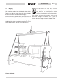
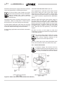
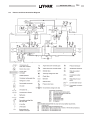
Product Description
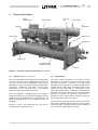
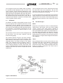
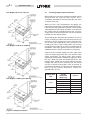
MOTOR
TERMINAL BOX
RUPTURE
DISK
COMPRESSOR
RELIEF VALVE
OIL
SEPARATOR
MOTOR
RELIEF VALVE
RELIEF VALVE
CONDENSER
SIGHT GLASS
MICROCOMPUTER
CONTROL CENTRE
COOLER
Figure 2.1 YS Rotary Screw Liquid Chiller (Front View)
2.1
General (Figures 2.1 and 2.2)
The York YS Millennium™ Rotary Screw Liquid Chiller
is primarily used for large air conditioning systems, but
may be used on other applications. Each unit is
completely factory-packaged including compressor,
evaporator, condenser, subcooler, oil separator,
lubrication system, isolation valves, drive motor,
optional motor starter and control centre.
Units are shipped as standard with a full charge of
refrigerant and oil. Units can also be shipped in sections
(optional) to accommodate job site requirements. An
optional shipping skid is also available for ease of
handling.
Exterior surfaces are protected with one coat of
Caribbean blue machinery paint.
2.2
Compressor
The rotary screw compressor uses state-of- the-art
technology to provide the most reliable and energy
efficient compressor available at all operating
conditions. The compressor is a positive displacement,
variable volume, direct drive, twin helical rotary screw
compressor. The male rotor is a direct drive by the
motor; the female rotor is an idler that is driven by the
male rotor. The rotors do not touch each other or the
compressor housing. The rotors are separated by a
hydraulic oil seal, which prevents high pressure gas
from leaking into low pressure areas.
The compressor housing is made of cast iron, precision
machined to provide minimal clearance for the rotors.
The housing has a design working pressure (DWP) of
24.1 bar and is hydro-tested at 37.5 bar.
2- 2
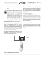
035L02381-GB0
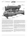
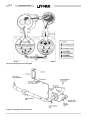
OIL
SEPARATOR
MOTOR
TERMINAL BOX
RELIEF
VALVE
RELIEF
VALVE
COOLER
CONDENSER
ISOLATION
VALVE
LIQUID LINE
ISOLATION VALVE
Figure 2.2 YS Centrifugal Liquid Chiller (Rear View)
The rotors are manufactured from forged steel and use
asymmetric profiles. The compressor incorporates a
complete anti-friction bearing design for reduced power
and increased reliability. Four separate cylindrical roller
bearings handle radial loads. Two 4-point angular
contact ball bearings handle axial loads. Together they
maintain accurate rotor positioning at all pressure ratios
thereby minimising blow-by and maintaining efficiency.
Oil is injected into the compressor by differential
pressure to lubricate the bearings, seal the rotors and
remove the heat of compression. The injected oil mixes
with the compressed gas and is separated from the
refrigerant gas in the oil separator.
The compressor has an oil reservoir located at the rotor
bearings to provide lubrication during start-up and
during coast-down even in the event of a power failure.
A check valve is installed in the compressor discharge
housing (suction housing for S4 and S5 compressors) to
prevent reverse running of the rotors due to system
refrigerant pressure gradients during shutdown.
The open-drive compressor shaft seal consists of a
spring-loaded, precision carbon ring, high temperature
elastomer "0" ring static seal, and stress-relieved,
precision lapped collars. The entire shaft seal cavity is at
low pressure, being vented to the oil drain from the
compressor, combining low pressure with direct oil
cooling for long seal life.
Capacity control is achieved by use of a slide valve
providing fully modulating capacity control from 10% to
100% of full load. The slide valve is positioned between
the male and female rotors and moves axially to match
the compressor capacity to that of the evaporator
refrigeration load. As the slide valve moves toward the
unloaded position, less suction gas is pumped through
the compressor.
The slide valve is actuated by oil pressure controlled by
external solenoid valves via the control centre. When
the compressor is shut off, a spring returns the slide
valve to unloaded position to ensure that the
compressor starts with the slide valve in the unloaded
position.
035L02381-GB0
2.3
Motor
The compressor motor is an open drip-proof, squirrel
cage induction type. The motor has a D-flange and cast
iron adaptor mounted rigidly to the compressor for
accurate alignment of motor and compressor shafts.
The motor drive shaft is connected to the compressor
shaft with a flexible disc coupling. Coupling has all metal
construction with no wearing parts to assure long life,
and no lubrication requirements to provide low
maintenance.
On units supplied without the optional solid state starter,
for use with a remote electromechanical starter, a large
steel motor terminal box with gasketed front access
cover is provided for field connected conduit. Six
terminals are provided in the terminal box, two for each
motor winding, allowing connection for star-delta (S/D)
or direct-on-line (DOL) starting. Jumpers are provided
for direct-on-line connection. Motor terminal lugs are not
provided. Overload/over-current transformers are fitted
as standard.
2.4
Oil Separator
The oil separator removes the oil that was injected into
the compressor. The separator is a horizontal three
stage design without moving parts.
Figure 2.3 Oil Seperator
2- 3
In the first stage of oil separation, high velocity oil and
refrigerant gas in the compressor discharge line under
goes a rapid reduction in velocity as it enters the large
diameter oil separator. Most of the oil drops out of the
refrigerant gas stream due to the reduction in velocity.
The oil falls by gravity into the oil reservoir located in the
bottom of the oil separator.
The second stage of oil separation is accomplished by
directing the refrigerant gas through mesh pads that
have an extended surface area. Smaller liquid oil
droplets are collected on the extended surface area of
the wire mesh pads where the oil falls by gravity into the
oil reservoir.
The third and final stage of oil separation is achieved in
the oil coalescing element section of the oil separator.
The oil mixed with the refrigerant entering the coalescer
element is a very fine aerosol mist. These small aerosol
mist particles wet the coalescer element media and form
larger oil droplets which fall by gravity to the bottom of
the coalescer element section. The oil collected in the
coalescer section is drained from the oil separator with a
small amount of refrigerant gas. This provides the high
pressure “gas drive” for the eductors to return oil from
the evaporator.
The oil separator has a design working pressure (DWP)
of 20.6 bar. The separator is fitted with a single or dual
pressure relief device (depending on safety code
requirements) set at 20 bar.
2- 4
035L02381-GB0
Three sight glasses are provided in the oil separator for
monitoring the oil level and verifying performance of the
coalescer element. Liquid oil should be visible in the top
glass of the oil separator when the chiller is off. During
operation, oil may be higher or lower due to system load
and operating conditions.
A low oil level safety switch is provided in the bottom of
the oil separator. A safety shutdown will be initiated if the
oil level is below the switch setting for a 30 second
period after the chiller has been running for 3 minutes.
An oil drain and charging valve is located on the bottom
of the oil separator. A 5/8 inch male flare connection is
provided for draining and charging. Oil can be added
into the oil reservoir with the chiller in service.
A temperature actuated 500 W (115 Vac-1 Ø-50 Hz)
immersion oil heater is located in the oil separator
reservoir to effectively remove refrigerant from the oil.
Power wiring is provided to the control centre.
2.5
Oil Filter
The oil flows from the oil separator through the 3 micron
oil filter. Filtered oil then flows to the oil manifold that is
located at compressor port SB-2.
A dual oil filter housing with isolation valves is standard
on all units. This allows switching between filters and
changing of the off line filter during operation. Units are
fitted as standard with two 3 micron absolute oil filters for
extended compressor life.
Figure 2.4 Oil Piping
2.6
Lubrication
An oil pressure transducer is located at the SB-2
manifold. The differential pressure is measured as the
difference between the oil pressure transducer at SB-2
and the filter pressure transducer located in the oil
separator.
This value is compared to the limits in the control panel
logic. If the oil filter differential reaches 20 PSID, a
warning message is displayed on the control panel, at
25 PSID, a safety shutdown is initiated.
Oil flows from the oil manifold at SB-2 to the plate type,
refrigerant cooled, oil cooler. Cool oil leaving the plate
heat exchanger flows to the eductor block manifold. The
eductor block manifold oil circuit contains the seal oil
pressure transducer and a high oil temperature safety
sensor. The differential pressure between the seal oil
pressure and the evaporator pressure transducer is
calculated and compared by the control panel. If the
differential reaches 20 PSID the control panel will initiate
a safety shutdown. A high oil temperature safety
shutdown will be initiated at 77°C.
The oil leaving the oil eductor manifold block flows into
the compressor at compressor port SB-3 to lubricate the
compressor bearings and shaft seal. The oil injected
into the compressor mixes with refrigerant gas during
compression. The oil and refrigerant gas is discharged
into the oil separator, where it is separated and returned
to the oil sump. A high discharge temperature safety is
located in the discharge line, between the compressor
and oil separator. This safety will initiate a safety
shutdown at 99°C.
035L02381-GB0
An oil supply line from the manifold at SB-2 is piped to
the capacity control directional valve at Port P. The
4-way capacity control solenoid (directional) valve
directs oil pressure against one side or the other of the
slide valve piston. The opposite side of the slide valve is
relieved to suction pressure at compressor port SC-11.
The differential pressure between the P port and the
suction pressure (Port SC-11) loads or unloads the slide
valve to provide capacity control.
2.7
2- 5
Oil-rich refrigerant flows into the eductor block through
the filter drier from the evaporator. The oil rich
refrigerant mixes with the discharge pressure gas and
flows into the compressor suction line.
A second eductor flows oil, collected in the evaporator
trough through the second filter drier located on the
eductor block. This oil mixes with the discharge gas in
the eductor block and flows to the compressor at port
SC-5.
Oil Eductor
2.8
Oil eductors are fitted to automatically recover any oil
that may migrate to the evaporator and return it to the
compressor. The oil eductor circuit manages the
amount of oil in the refrigerant charge. A small amount of
oil is normal in the refrigerant charge and will be found in
the evaporator. If not properly managed the oil will
accumulate and have an adverse affect on unit
performance.
The oil eductor circuit consists of three refrigerant and
oil filter driers, two “jet pump” eductors and the
interconnecting piping.
The eductors operate using the “jet pump” principle.
Discharge pressure gas and oil flows through a filter
dryer located at the bottom of the oil separator to a
regulating orifice and nozzle located in the eductor
block. The reduced pressure (pumping action) is
created by the velocity of the discharge pressure gas
and oil flowing through the orifice and nozzle. This
creates a reduced pressure area that allows the oil-rich
refrigerant and oil to flow from the evaporator into the
compressor.
Figure 2.5 Oil Eductor
Heat Exchangers
Shells
Evaporator and condenser shells are fabricated from
rolled carbon steel plates and have fusion welded
seams. Carbon steel tube sheets, drilled to
accommodate the tubes, are welded to the ends of each
shell. Intermediate tube supports are fabricated of 12.7
mm thick carbon steel plates, no more than 1220 mm
apart. The refrigerant side of each shell has a design
working pressure of 20.6 bar and is tested at 31.0 bar.
Each vessel has a single or dual refrigerant relief device
set at 20.6 bar.
Tubes
Heat exchanger tubes are each 19 mm OD, 0.71 mm
wall copper alloy with a high efficiency, internally and
externally enhanced design to provide optimum
performance. Each tube is roller expanded into the tube
sheets to provide a leak-proof seal. Each tube is
individually replaceable.
2- 6
035L02381-GB0
Figure 2.6 Refrigerant Flow Diagram
Figure 2.7 Refrigerant Flow Control
035L02381-GB0
2.9
Evaporator
The evaporator is a shell and tube, flooded type, heat
exchanger with a distributor trough providing uniform
distribution of refrigerant over the entire shell length to
ensure optimum heat transfer. A 57 mm diameter liquid
level sight glass is located on the side of the shell to aid
in determining proper refrigerant charge. A 25 mm
refrigerant charging valve is provided.
2.10 Condenser
The condenser is a shell and tube, flooded type, heat
exchanger with a discharge gas baffle to prevent direct
high velocity impingement on the tubes. The baffle
distributes the refrigerant gas flow uniformly over the
entire shell length for optimum heat transfer. A
subcooler section is located in the bottom of the
condenser to provide effective liquid refrigerant
subcooling, improving cycle efficiency. The condenser
shell also serves as a refrigerant receiver to store the
system charge during servicing. Manually operated
isolation valves are located at the inlet and outlet of the
condenser. Valves are also provided to facilitate
removal of the refrigerant from the system.
2.11 Refrigerant Flow Control
Sub-cooled liquid refrigerant flows out of the condenser
via the liquid line into the evaporator by differential
pressure. A single or dual fixed metering orifice with no
moving parts controls refrigerant flow to the evaporator.
The orifice is selected based upon the operating
conditions of the unit.
A variable orifice arrangement is also supplied in
parallel with the metering orifice. This consists of a
solenoid valve and hand-throttling valve. The solenoid is
energized open by the differential pressure set point that
is field programmable in the control panel.
The differential pressure between condensing pressure
and evaporating pressure is compared to the set point
value. When the differential pressure is at or less than
the setpoint, the solenoid valve is energized open. The
solenoid valve is de-energized closed when the
differential pressure is equal to or greater than the
setpoint plus 10 PSIG. A hand-throttling valve is
provided to adjust the refrigerant flow rate through the
solenoid valve to match the system operating
conditions.
2- 7
A manual isolation valve is located between the
condenser and the metering orifice plate. This valve, in
combination with the hand isolation valve between the
oil separator and the condenser, allows all of the
refrigerant charge to be stored in the condenser.
A liquid refrigerant supply is piped from the bottom of the
liquid line to the refrigerant cooled oil cooler. The
refrigerant gas from the oil cooler is piped directly into
the evaporator. A refrigerant charging valve is fitted into
the liquid line between the evaporator and the metering
orifice. A ¾ inch male flare connection is provided for
connecting hoses or transfer lines.
2.12 Capacity Control
Capacity control is accomplished by using differential
pressure to move the slide valve. As the slide valve is
moved axially between the compressor rotors the
volume of vapour pumped by the compressor is
changed to match the system requirements.
Leaving chilled water temperature (LCWT) is
continuously monitored by the microprocessor and
compared to the LCWT Setpoint. When the LCWT is
outside the range of the setpoint value a signal is sent
via the relay output board to energize the 4-way valve
directional solenoid valves.
When solenoid valve B is energised (Port P to Port B
and Port A to Port T) the slide valve moves in the load
direction.
High pressure oil from the oil circuit flows (Port P) flows
through the sub-plate manifold block and out to
Compressor Port SC-2 (Port B). Simultaneously, oil
flows out of Compressor Port SC-1 (Port A) through the
sub-plate manifold block and out to suction pressure
(Port T).
When the Solenoid Valve A is energised (Port P to Port
A and Port B to Port T), the slide valve moves in the
unload direction. High pressure oil flows into
Compressor Port SC-1 (Port A) and oil is relieved out of
Compressor Port SC-2 (Port B) to suction pressure.
A slide valve potentiometer is used to provide feedback
to the microprocessor to display slide valve position as a
percentage of full load.
Four manual isolation valves are incorporated into the
4-way solenoid sub-plate to isolate the 4-way directional
valve for service.
2- 8
035L02381-GB0
Figure 2.6 Capacity Control
2.13 Water Boxes
2.14 Control Centre
Removable water boxes fabricated from heavy gauge
sheet steel are fitted to each end of both heat
exchangers. The design working pressure is 10 bar and
the boxes are tested at 15 bar. Integral steel water
baffles are located and welded within the water boxes to
provide required pass arrangements. Stub-out water
nozzle connections with Victaulic grooves are welded to
the water boxes. These nozzle connections are suitable
for Victaulic couplings, welding or flanges, and are
capped for shipment. Plugged 19mm drain and vent
connections are provided in each evaporator and
condenser water box.
The control centre is factory mounted, wired and tested.
The centre automatically controls the operation of the
unit in meeting cooling requirements while minimising
energy usage. Unit operating parameters are sensed by
thermistors and transducers and can be viewed on the
keypad display. All pressures are taken as gauge
pressure. Temperatures and pressures can be
displayed in Imperial ('F, psig) or metric ('C, kPa) as
required. Display of all information is shown in the
English language on a 40-character alphanumeric
display.
Available operating information includes return/leaving
chilled liquid temperatures; return/leaving condenser
water temperatures; evaporator/condenser refrigerant
pressures; oil pressures at compressor and oil filter
di f f er ent i al ;
per cent
mot or
curr e n t ;
evaporator/condenser saturation temperatures;
compressor discharge temperature; oil temperature;
percent slide valve position, operating hours and
number of compressor starts.
035L02381-GB0
2- 9
The control centre includes unique safety logic to
protect the unit from damaging malfunctions.
Comprehensive information can be displayed in the
event of a unit shutdown including day, time, and reason
for shutdown. Reasons include high condenser
pressure, low oil pressure at compressor, clogged oil
filter, low oil level in oil separator, high oil temperature,
high oil pressure, high compressor discharge
temperature, low evaporator pressure, motor controller
fault, and sensor malfunction.
2.15 Options and Accessories
Background messages are displayed while the unit is
running to inform of any controlling conditions such as:
current limit in effect, low pressure limit in effect, high
pressure limit in effect, leaving chilled water
temperature control, and non-critical sensor error.
System cycling messages are displayed in regard to
day, time, cause of cycling shutdown, and auto start
indication. These include low water temperature,
evaporator/condenser water flow interruption, internal
time clock, and anti-recycle.
Standard features include: digital readout at the control
centre of 3-phase voltage and current; high and low line
voltage protection; 115 V control transformer; three-leg
sensing overloads; phase rotation and single-phase
failure protection; and momentary power interruption
protection. An integral door interlocked and
pad-lockable fused disconnect switch is also available.
Digital programming of operating setpoints from the
keypad include leaving chilled water temperature,
current limiting, pulldown demand limiting, daily
start/stop scheduling of chiller, pumps and tower, and
separate holiday schedule.
Individual LED indicators highlight slide valve loading/
unloading/auto control, program mode, and display
hold.
Manual operation of slide valve loading and unloading is
provided through separate buttons in the service section
of the keypad.
All operating and setpoint information can be
transmitted to a remote printer through the RS-232 port
in the control centre to obtain data logs. This can be
accomplished at any time by pressing the "Print" button
on the control centre keypad, or automatically at
predetermined intervals by programming the panel.
The remote printer will also record time and cause of any
safety or cycling shutdown and a history of the last four
shutdowns.
The control centre is compatible with remote Building
Automation Systems (BAS) and Energy Management
Systems (EMS). The remote control functions available
as standard include start and stop, leaving chilled water
temperature reset and current limit reset through PWM
signal, and "ready to start", "safety" and "cycling"
shutdown status contacts. Further remote control
features are available via an optional York ISN
translator.
Motor Starter
The solid state starter is a reduced voltage starter that
controls and maintains a constant current flow to the
motor during start-up. It is compact and mounted on the
unit adjacent to the motor terminals. Power and control
wiring is factory supplied. The starter enclosure is IP33
rated with a hinged access door with lock and key.
BAS/EMS Remote Control Interface
A communication interface permitting complete
exchange of unit data with any BAS/EMS is available via
an optional ISN translator. The ISN translator also
allows a BAS/EMS to issue commands to the unit to
control its operation. ISN translators are available in two
models for controlling up to four, or up to eight units.
Remote Reset Controls
Optional PCB to allow reset of leaving chilled water
temperature and percent motor current limit by a BAS/
EMS using 4-20 mA, 0-10 Vdc, or discrete stepped
signals rather than the standard pulse width modulated
(PWM) signal requirement.
Factory Insulation of Evaporator
Factory-applied 19 mm thick anti-sweat insulation
(flexible, closed-cell plastic type) is attached with
vapour-proof cement to the evaporator shell, flow
chamber, evaporator tube sheets, suction connection,
and (as necessary) to the auxiliary tubing. This
i nsul at i on w i l l nor mal l y pr event sw ea t in g in
environments with relative humidity up to 75% and dry
bulb temperatures ranging from 10°C to 32°C. 38 mm
thick insulation is also available for environments with
relative humidity up to 90% and dry bulb temperatures
ranging from 10°C to 32°C. Insulation of water boxes
and nozzles is not included.
2-10
035L02381-GB0
High Water Side Pressure Heat Exchangers
VBG 20 Compliance Kit
One or both of the evaporator and condenser may be
supplied with a water side design pressure of 20 bar
(subject to pressure vessel code approval availability).
Factory fitted T.Ue.V. approved mechanical high
pressure cut-out switches (two) as required to comply
with some safety codes.
Water Flanges
Mechanical Low Pressure Cut-out
Four BS4504/ ISO7005 - NP10 raised-face flanges can
be supplied factory welded or for site welding to the
condenser and evaporator water nozzles (companion
flanges, bolts, nuts and gaskets are not included).
Available for under pressure protection on low
temperature glycol chilling applications.
Water Flow Switches
Spring Isolation mounting is recommended instead of
standard isolation mounting pads for all upper floor
locations. Four level adjusting spring-type vibration
isolator assemblies with non-skid pads are provided
with mounting brackets for field installation. Isolators are
designed for 25 mm deflection.
Paddle-type, vapour-proof water flow switches can be
supplied suitable for 10 bar DWP chilled and condenser
water circuits. This or an equivalent switch must be fitted
in the chilled water circuit to protect against loss of water
flow. A condenser water flow switch is optional.
Spring Isolation Mounts
Printer
Hot Gas Bypass System
A hot gas bypass system can be factory installed to
allow unit operation down to virtually zero load if
required.
Hand held printer for obtaining a printout of unit
operating data and history data from the control centre.
2.16 Nomenclature
YS BB BA
S2
5
CF
D
Model
S
Special Modifications
Cooler Code
Design Level
Condenser Code
Motor Code
Power Supply:
5 for 50 Hz
Compressor Code
2.17 Range of Models
COMPRESSOR
COOLER
CODE
CODE
BA, BB
S2
CA, CB
DA, DB, DC
CA, CB,
S3
DA, DB, DC
DA, DB, DC
S4
EA, EB, EC
FA, FB, FC
EA, EB, EC
S5
FA, FB, FC
CONDENSER
CODE
BA, BB, CA, CB
BA, BB, CA, CB, DA, DB
CA, CB, DA, DB
CA, CB, DA, DB
CA, CB, DA, DB
CA, CB, DA, DB
EA, EB, FA, FB
EA, EB, FA, FB
EA, EB, FA, FB
EA, EB, FA, FB
MOTOR
CODE
5CC, 5CD,
5CE, 5CF,
5CG, 5CH
5CC, 5CD, 5CE, 5CF,
5CG, 5CH, 5CI, 5CJ, 5CK
5CE, 5CF, 5CG, 5CH,
5CI, 5CJ, 5CK, 5CL,
5CM, 5CN, 5CO
5CF, 5CG, 5CH, 5CI, 5CJ,
5CK, 5CL, 5CM, 5CN, 5CO
035L02381-GB0
3
TRANSPORTATION, RIGGING AND STORAGE
3.1
General
3- 1
4.
Do not make final power supply connections to the
compressor motor, solid state starter or control
centre.
5.
Do not charge the compressor with oil.
6.
Do not charge the unit with refrigerant.
Units can also be shipped dismantled when required by
rigging conditions, but generally it is more economical to
enlarge access openings to accommodate the factory
assembled unit. Units shipped dismantled MUST be
field assembled under the supervision of a York
representative.
7.
Do not attempt to start the system.
8.
Do not run hot water (40°C maximum.) or steam
through the cooler or condenser at any time.
FIELD ASSEMBLED UNITS ONLY
The unit may be ordered and shipped in any of the
following forms:
YS units are shipped as a single factory assembled,
piped, wired package, requiring minimum installation to
make chilled water connections, condenser water
connections, refrigerant atmospheric relief connections,
and electrical power connections.
Use Form 160.47-N3.1 in conjunction with this manual.
This instruction will be furnished with all units that are to
be field assembled.
A York authorised representative must check the
installation, supervise the initial start-up and operation
of all newly installed units.
3.2
Shipment
Form 1 – Factory Assembled Unit (complete with
motor, refrigerant and oil charges)
1.
The York Warranty may be voided if the
following restrictions are not adhered to:
The motor/compressor assembly mounted, with all
necessary interconnecting piping assembled.
Control centre is mounted on the unit. Complete
unit factory leak tested, evacuated and charged
with R134a.
An optional Solid State Starter can be factory
mounted and wired.
1.
No valves or connections should be opened under
any circumstances because such action will result
in loss of the factory nitrogen charge.
2.
Do not dismantle or open the unit for any reason
except under the supervision of a Yor k
representative.
3.
2.
Miscellaneous material – Four (4) vibration
isolation pads (or optional spring isolators and
brackets).
Form 2 – Factory Assembled Unit (complete with
motor, refrigerant and oil charges shipped separately).
1.
When units are shipped dismantled, notify the
nearest York office in ample time for a York
representative to supervise rigging the unit to its
operati ng position and the assembl y of
components.
The motor/compressor assembly mounted, with all
necessary interconnecting piping assembled.
Control centre is mounted on the unit. Complete
unit factory leak tested, evacuated and charged
with holding charge of nitrogen.
An optional Solid State Starter can be factory
mounted and wired.
2.
Miscellaneous material – Four (4) vibration
isolation pads (or optional spring isolators and
brackets).
3- 2
035L02381-GB0
Form 3 – Motor/Compressor Separate From Shells
3.3
Inspection, Damage and Shortage
Shipped as three major assemblies. Unit first
factory assembled, refrigerant piped, wired and
leak tested; then dismantled for shipment.
Compressor/motor assembly removed from shells
and skidded. Cooler/condenser shells are not
skidded.
The unit shipment should be checked on arrival to see
that all major pieces, boxes and crates are received.
Each unit should be checked before unloading, for any
visible signs of damage. Any damage or signs of
possible damage must be reported to the transportation
company immediately for their inspection.
All compressor wiring attached, and all conduit is
left on shell. All openings on compressor, oil
separator, and shell are closed and charged with
dry nitrogen (0.14 to 0.2 barg).
York will not be responsible for any damage in
shipment or at job site or loss of parts.
Miscellaneous packaging of control centre, tubing,
water temperature controls, wiring, oil, isolators,
solid state starter (option), etc., refrigerant charge
shipped separately.
U ni ts shipped dismantled MUST be
re-assembled by, or under the supervision of,
a York representative.
(See Form 160.47-N3.1)
Form 7 – Split Shells
Shipped as four major assemblies. Unit first factory
assembled, refrigerant piped, wired and leak
tested; then dismantled for shipm ent .
Compressor/motor assembly removed from shells
and skidded.
Cooler and condenser shells are separated at tube
sheets and are not skidded. Refrigerant lines
between shells are flanged and capped, requiring
no welding.
All compressor wiring attached. All wiring
harnesses on shells are removed. All openings on
compressor and shells are closed and charged
with dry nitrogen (0.14 to 0.2 barg).
Miscellaneous packaging of control centre, tubing,
water temperature controls, wiring, oil isolators,
solid state starter (option), etc.; refrigerant charge
shipped separately.
U ni ts shipped dismantled MUST be
re-assembled by, or under the supervision of,
a York representative.
(See Form 160.47-N3.1)
When more than one unit is ordered, the major parts of
each unit will be marked to prevent mixing of
assemblies. (Piping and Wiring Drawings will be
furnished by York.)
When received at the job site all containers should be
opened and contents checked against the packing list.
Any material shortage should be reported to York
immediately.
Chiller Data Plate
A unit data plate is mounted on the control panel
assembly of each unit, giving unit model number; design
working pressure; water passes; refrigerant charge;
serial numbers; and motor power characteristics and
connection diagrams.
Additional information may be found on the motor data
plate. This information should be included when
contacting the factory on any problem relating to the
motor.
035L02381-GB0
3.4
Rigging
The complete standard unit is shipped without skids.
(When optional skids are used it may be necessary to
remove the skids so riggers skates can be used under
the unit end sheets to reduce overall height.)
Each unit has four (4) lifting holes (two in each end) in
the end sheets which should be used to lift the unit.
Care should be taken at all times during rigging and
handling of the chiller to avoid damage to the unit and its
external connections. Lift only using holes shown.
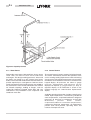
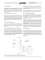
Figure 3.1Rigging
3- 3
Do not lift the unit with slings around
motor/compressor assembly or by means of
eye bolts in the tapped holes of the
compressor motor assembly. Do not turn a
unit on its side for rigging. Do not rig vertically.
The rigging and operating weights and overall
dimensions are given in Section 9 as a guide in
determining the clearances required for rigging. (Add
150 mm to overall height for optional skidded unit.).
3- 4
035L02381-GB0
Page Left Intentionally Blank
035L02381-GB0
4
INSTALLATION
4.1
Location
4.5
4- 1
Rigging Unit to Final Location
YS units are furnished with vibration isolator mounts for
basement or ground level installations. Units may be
located on upper floor levels providing the floor is
capable of supporting the total unit operating weight and
optional spring isolators are used.
Rig the unit to its final location on the floor or mounting
pad, lift the unit (or shell assembly) by means of an
overhead lift and lower the unit to its mounting position.
(If optional shipping skids are used, remove them before
lowering the chiller to its mounting position.)
Sufficient clearance to facilitate normal service and
maintenance work must be provided all around and
above the unit and particularly space provided at either
end to permit cleaning or replacement of cooler and
condenser tubes. (See CLEARANCES).
At this point units shipped dismantled should
be assembled under the supervision of a York
representative.
A doorway or other sufficiently large opening properly
located may be used. The chiller should be located in an
indoor location where temperatures range from 4°C to
43°C.
4.2
4.6
Motors
The YS motor is air cooled. Check national, local and
other codes for ventilation requirements.
4.3
Foundation
A level floor, mounting pad or foundation must be
provided by others, capable of supporting the operating
weight of the unit.
4.4
Clearances
Clearances should be adhered to as follows:
Rear and above unit – 600 mm.
Front of unit – 900 mm.
Tube Removal – see table below
COMPRESSOR
S2, S3
S4, S5
If cooler is to be field insulated, the insulation should be
applied to the cooler before the unit is placed in position
while the unit is in the lift position. Be sure unit is properly
supported. (See INSULATION).
TUBE REMOVAL SPACE (mm)
3073
3683
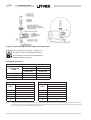
Locating and Installing Isolator Pads
The isolator pad mounts are to be located as shown in
Figure 4.1
After the isolator pads have been placed into position on
the floor, lower the chiller onto the pads. When the unit is
in place, remove the rigging equipment and check that
the unit is level both longitudinally and transversely. The
unit should be level within 6 mm from one end to the
other end and from front to the rear. If the chiller is not
level within the amount specified, lift it and place shims
between the isolation pad and the chiller tube sheets.
(Shims furnished by the installer.) Lower unit again and
recheck to see that it is level.
Checking the Isolator Pad Deflection
All isolator pads should be checked for the proper
deflection while checking to see if the unit is level. Each
pad should be deflected approximately 4 mm. If an
isolation pad is under-deflected, shims should be placed
between the unit tube sheet and the top of the pad to
equally deflect all pads.
Levelling the Unit
The longitudinal alignment of the unit should be checked
by placing a level on the top centre of the cooler shell
under the compressor/motor assembly. Transverse
alignment should be checked by placing a level on top of
the shell end sheets at each end of the chiller.
4- 2
035L02381-GB0
Unit Weights less than 7423 kg
4.7
Installing Optional Spring Isolators
When ordered, 4 spring type isolator assemblies will be
furnished with the unit (see table below). The 4
assemblies are identical and can be placed at any of the
4 corners of the unit.
While the unit is still suspended by the rigging, the
isolator mounting brackets should be bolted to the unit .
Place the four spring isolators in position. The threaded
adjusting bolts in each isolator should be screwed out of
the isolator until the extended head of the screw fits
snugly into the isolator bracket hole. The unit should be
lowered over the adjusting bolts.
Unit Weights 7546 kg to 13080 kg
The levelling bolts should now be rotated one (1) turn at
a time, in sequence, until the unit end sheets are clear of
the floor by 22 mm and the unit is level. Check that the
unit is level, both longitudinally and transversely (see
Levelling the Unit). If the levelling bolts are not long
enough to level unit due to an uneven or sloping floor or
foundation, steel shims (grouted, if necessary) must be
added beneath the isolator assemblies as necessary.
After the unit is levelled, wedge and shim under each
corner to solidly support the unit in this position while
piping connections are being made, pipe hangers
adjusted and connections checked for alignment. Then
the unit is filled with water and checked for leaks. The
levelling bolts should now be finally adjusted until the
wedges and shims can be removed. The unit should
now be in correct level position, clear of the floor or
foundation and without any effect from the weight of the
pi pi ng ( spr i ng i sol at or def l ect i on shoul d b e
approximately 25 mm).
COMPRESSOR
SIZE
Unit Weights 13080 kg to 24281 kg
S2, S3
S4, S5
Figure 4.1 Neoprene Isolators
SYSTEM
OPERATING
WEIGHT (kg)
PART No.
Up to 5525
029-18479-003
5526 to 6927
029-18479-004
6928 to 8288
029-18480-001
8289 to 10392
029-18480-002
Up to 10392
029-18480-002
10393 to 11813
029-18480-003
11814 to 14561
029-18480-004
035L02381-GB0
4- 3
Check for piping alignment – Upon completion of
piping, a connection in each line as close to the unit as
possible should be opened, by removing the flange bolts
or coupling and checked for piping alignment. If any of
the bolts are bound in their holes, or if the connection
springs are out of alignment, the misalignment must be
corrected by properly supporting the piping or by
applying heat to anneal the pipe.
If the chiller/cooling water piping needs to be
welded directly to the water pipe nozzles, the
temperature sensors should be removed to
prevent heat damage.
If the piping is annealed to relieve stress, the
inside of the pipe must be cleaned of scale
before it is finally bolted in place.
4.9
Cooler and Condenser Water Piping
The cooler and condenser liquid heads have nozzles
which are grooved, suitable for welding 10.3 bar DWP
flanges or the use of Victaulic couplings. Factory
mounted flanges are optional.
The nozzles and water pass arrangements are
delivered in accordance with the job requirements (see
Product Drawings delivered with the job and Section 9).
Standard units are designed for 10.3 bar DWP on the
water side. If job requirements are for greater than
10.3 bar DWP, check the unit Data Plate before applying
pressure to cooler or condenser to determine if the
chiller has provisions for the required DWP.
Inlet and outlet connections are identified by labels
placed adjacent to each nozzle.
Figure 4.2 Optional Spring Isolators
4.8
Foreign objects which could lodge in, or block flow
through the cooler and condenser tubes must be kept
out of the water circuit. All water piping must be cleaned
or flushed before being connected to the chiller pumps,
or other equipment.
Piping Connections
After the unit is levelled (and wedged in place for
optional spring isolators) the piping connections may be
made; chilled water, condenser water and refrigerant
relief. The piping should be arranged with offsets for
flexibility, and adequately supported and braced
independently of the unit to avoid strain on the unit and
vibration transmission. Hangers must allow for
alignment of pipe. Isolators (by others) in the piping and
hangers are highly desirable, and may be required by
specifications, in order to effectively utilise the vibration
isolation characteristics of the vibration isolation mounts
of the unit.
Permanent strainers (supplied by others) are required in
both the cooler and condenser water circuits to protect
the chiller as well as the pumps, tower spray nozzles,
chilled water coils and controls, etc. The strainer should
be installed in the entering chilled water line, directly
upstream of the chiller.
Water piping circuits should be arranged so that the
pumps discharge through the chiller, and should be
controlled as necessary to maintain essentially constant
chilled and condenser water flows through the unit at all
load conditions.
4- 4
035L02381-GB0
If pumps discharge through the chiller, the strainer may
be located upstream from pumps to protect both pump
and chiller. (Piping between strainer, pump and chiller
must be very carefully cleaned before start-up.) If
pumps are remotely installed from chiller, strainers
should be located directly upstream of the chiller.
4.10 Water Treatment
The unit performance given in the Design Guide is
based on a fouling factor of 0.044 m² °C/kW (0.00025
ft²hr °F/Btu). Dirt, scale, grease and certain types of
water treatment will adversely affect the heat exchanger
surfaces and therefore unit performance. Foreign
matter in the water system(s) can increase the heat
exchanger pressure drop, reducing the flow rate and
causing potential damage to the heat exchanger tubes.
Aerated, brackish or salt water is not recommended for
use in the water system(s). York recommend that a
water treatment specialist is consulted to determine that
the proposed water composition will not affect the
evaporator materials of carbon steel and copper. The
pH value of the water flowing through the heat
exchangers must be kept between 7 and 8.5.
Figure 4.3 Typical Piping Arrangement
4.11 Glycol Solutions
For unit operation with chilled liquid temperatures
leaving the cooler at below 4°C, glycol solutions should
be used to help prevent freezing. Section 9, gives
recommended solution strength with water, as a
percentage by weight, for the most common types of
glycol. It is important to check glycol concentration
regularly to ensure adequate concentration and avoid
possible freeze-up in the cooler.
When using glycol solutions, pressure drops
are higher than with water. Special care must
be taken not to exceed the maximum pressure
drop allowed.
4.12 Condenser Water Circuit
For proper operation of the unit, condenser refrigerant
pressure must be maintained above cooler pressure. If
operating conditions will fulfill this requirement, no
attempt should be made to control condenser water
temperature by means of automatic valves, cycling of
the cooling tower fan or other means, since chillers are
designed to function satisfactorily and efficiently when
condenser water is allowed to seek its own temperature
level at reduced loads and off-peak seasons of the year.
However, if entering condenser water temperature can
go below the required minimum, condenser water
temperature must be maintained equal to or slightly
higher than the required minimum. Refer to Figure 4.3
for a typical water piping schematic.
035L02381-GB0
4.13 Stop Valves
Stop valves may be provided (by others) in the cooler
and condenser water piping adjacent to the unit to
facilitate maintenance. Thermometer wells and
pressure taps should be provided (by others) in the
piping as close to the unit as possible to facilitate
operating check.
4- 5
Fill the chilled and condenser water circuits, operate the
pumps manually and carefully check the cooler and
condenser water heads and piping for leaks. Repair
leaks as necessary.
Before initial operation of the unit both water circuits
should be thoroughly vented of all air at the high points.
4.17 Refrigerant Relief Piping
4.14 Flow Switches (Field Installed)
A flow switch or pressure differential control in the
chilled water line(s) adjacent to the unit is an accessory
furnished for connection to the control panel. If a flow
switch is used, it must be directly in series with the chiller
and sensing only water flow through the chiller. The
differential switch must sense pressure drop across the
unit.
4.15 Drain and Vent Valves
Drain and vent valves (by others) should be installed in
the connections provided in the cooler and condenser
liquid heads. These connections may be piped to drain if
desired.
Each unit is equipped with pressure relief valves located
on the condenser, oil separator and evaporator for
relieving excess pressure of the refrigerant charge to
the atmosphere as a safety precaution in case of an
emergency, such as fire.
Refrigerant relief vent piping (by others), from the relief
valves to the outside of the building, is required by code
in most areas and should be installed on all chillers. The
vent line should be sized in accordance with the
ANSI/ASHRAE-15, or local code. The vent line must
include a dirt trap in the vertical leg to intercept and
permit clean out and to trap any vent stack
condensation. The piping MUST be arranged to avoid
strain on the relief valves, using a flexible connection, if
necessary.
4.16 Checking Piping Circuits and Venting Air
4.18 Unit Piping
After the water piping is completed, but before any water
box insulation is applied. Tighten and torque (to
maintain between 41 and 82 Nm) the nuts on the liquid
head flanges. Gasket shrinkage and handling during
transit may cause the nuts to loosen. If water pressure is
applied before tightening is done, the gaskets may be
damaged and have to be replaced.
Compressor lubricant piping and system external piping
are factory installed on all units shipped assembled. On
units shipped dismantled, the lubricant piping to oil
sump and oil cooler and system oil return connections
should be completed, under the supervision of the York
representative, using material furnished. See Form
160.47-N3.1.
Figure 4.4 Typical Refrigerant Vent Piping from Relief Valves
4- 6
035L02381-GB0
Figure 4.5 Typical Refrigerant Vent Piping from Rupture Disk
Piping should be properly supported to
prevent any strain on bursting disk mounting.
Be careful not to puncture bursting disk when
thread protector is removed.
Refrigerant Relief Sizes
OIL SEPARATOR
RELIEF VALVE
RUPTURE DISK
DUAL (1)
SINGLE
OUTLET NPT
OUTLET NPT
COMPRESSOR
CODE
S2, S3 (2)
3/4"
2"
S4 (2)
1"
2-1/2"
S5 (2)
1"
2-1/2"
COOLER
CONDENSER
SINGLE RELIEF VALVE
SHELL
OUTLET
DUAL RELIEF VALVE
SHELL
NPT
Notes:
OUTLET
NPT
B
3/4"
B
3/4"
C
3/4"
C
3/4"
D
1"
D
3/4"
E
1"
E
1"
F
1"
F
1"
1). Dual relief valve consists of one three-way shut off valve and two single relief valves. The valve configuration will not allow both valves to be shut off at
the same time, and valves are sized such that each relief valve has sufficient discharge capacity when used alone. This permits safe removal of either relief
valve for repair or replacement, while maintaining vessel protection.
035L02381-GB0
4.19 Electrical Connection
The following connection recommendations are
intended to ensure safe and satisfactory operation of the
unit. Failure to follow these recommendations could
cause harm to persons, or damage to the unit, and may
invalidate the warranty.
4- 7
The main 'START/RUN/STOP-RESET' selector switch
on the control centre must remain in 'STOP/RESET'
position until the unit is commissioned by authorised
personnel. If the switch has been placed in the 'RUN' or
'START' position before commissioning, this must be
reported to York otherwise warranty may be invalidated.
No additional controls (relays, etc.) should
be mounted in the control panel. Power
and control wiring not connected to the
control panel should not be run through
the control panel. If these precautions are
not followed it could lead to a risk of
electrocution. In addition, electrical noise
could cause malfunctions or damage the
unit and its controls.
4.20 Power Wiring
After connection do not switch on mains
power to the unit until it has been
commissioned by York Authorised
personnel. Some internal components are
live when mains is switched on.
Units supplied without a starter require one three phase
supply to the motor from a remote electro mechanical
starter (field supplied). A 115 Vac - 1Ph - 50 Hz supply of
15 amp capacity is also required for the control centre.
An optional control transformer (1-1/2 KVA required) is
available to meet this requirement.
On units shipped disassembled, after installation of the
control panel, control wiring must be completed
between unit components and control panel or solid
state starter, when used, using wiring harness
furnished.
No changes in unit wiring from that shown on
drawings delivered shall be made without
prior approval of the York representative.
All electrical wiring should be carried out
in accordance with local regulations.
Customer supplied isolators and fuses
may be installed next to the unit, avoiding
locations close to refrigerant and water
lines.
All sources of supply to the unit must be
taken via a common point of isolation (not
supplied by York).
After connection DO NOT switch on mains
or control system power to the unit. Some
internal components are live as soon as
mains is switched on the unit and this must
only be done by authorised persons.
Units are suitable for 380/400V - 3 Ph - 50 Hz or 415V - 3
Ph - 50 Hz nominal power supplies only. The correct
electrical power supply is given on the unit data plate,
which also details the motor connection diagrams.
4.20.1 Units with Electro-Mechanical Starter
(field supplied)
Electro-Mechanical starters for the unit must
be furnished in accordance with York
Standard R-1079 to provide the features
necessary for the starter to function properly
with the York control system.
Route the cables forming the 3 phase power supply via
the same hole in the motor terminal box gland plate,
using a suitable cable gland, to ensure that no eddy
currents are set up in the metal gland plate. If separate
entries for each cable forming the 3 phase supplies are
used, the metal gland plate must be replaced by a
non-metallic gland plate.
DO NOT cut wires to final length or make final
connections to the motor or starter power input
terminals until approved by a York representative. To
ensure correct motor rotation the starter power input
and starter to motor connections must be checked with a
phase sequence indicator in the presence of the York
representative.
Route the main earth cable via the motor terminal box
gland plate to the main earth connection stud on the side
of the box.
Route the single phase control supply to the control
centre with bare wire ends of maximum cable size
4 mm². Also connect an earth wire to the earth terminal
using the M4 lug.
4- 8
035L02381-GB0
DO NOT make final power supply connections to control
centre until approved by a YORK representative.
To ensure proper motor rotation the starter
power input and starter to motor connections
must be checked with a phase sequence
indicator in the presence of the York
representative.
The figure below shows the power wiring for the motor
connections. (Refer to wiring labels in motor terminal
box for details to suit motor voltage and amperage.)
For high voltage applications motor leads are furnished
with a crimp type connection having a clearance hole for
a 3/8" bolt, motor terminal lugs are not furnished.
For low voltage applications terminal block connections
are fitted.
4.20.2 Units with Solid State Starter (Optional)
Units equipped with a solid state starter require a three
phase power supply plus earth to the starter. Power
wiring from the starter to the motor is factory fitted.
Power wiring to the control centre is also factory fitted
via a control transformer supplied with the Solid State
Starter.
Route the cables forming the 3 phase power supply via
the same hole in the solid state starter gland plate /
gland box on top of the starter, using a suitable cable
gland, to ensure that no eddy currents are set up in the
metal gland plate. If separate entries for each cable
forming the 3 phase supplies are used, the metal gland
plate / gland box must be replaced by a non-metallic
version.
DO NOT cut wires to final length or make final
connections to starter input terminals until approved by
a York representative.
To ensure proper motor rotation the starter
power input connections must be checked
with a phase sequence indicator in the
presence of the York representative.
Route the earth cable via the starter gland plate to the
main earth connection stud on the side of the starter.
4.21 Control Connections
Customer voltage free contacts must be
suitable for device contact rating to be 5 mA at
115 Vac. If the voltage free contacts form part
of a relay or contactor, the coil of the device
Figure 4.6 Motor Connections (Electro-Mechanical Starter)
035L02381-GB0
MUST be suppressed using a standard R/C
suppressor to avoid electrical noise which
could cause a malfunction or damage to the
unit.
To avoid the possibility of motor failure due to
excessive start cycles, the unit should not
normally be cycled using the remote
connections. Cycling of the unit based on
cool i ng demand is accom pl i shed
automatically by the control centre. In
addi tion, the control centre has a
programmable time clock function as a
standard feature with holiday capability. This
offers one preset automatic Start-Stop per
day on a seven day calendar basis with the
ability to program a single additional holiday
start and stop time up to a week in advance.
4.21.1 Remote Start / Stop (R/STT - TB2: terminals 1 & 7)
(R/STP - TB2: terminals 1 & 8)
With the control centre is in the "REMOTE" operating
mode, the "COMPRESSOR' switch is in the "run"
position and the Remote Ready to Start Contacts
indicate the unit is ready to start, holding contacts open
across the Remote Stop Connections and closing
contacts across the Remote Start Connections will start
the unit. A subsequent closure of the Remote Stop
Contacts causes the unit to shutdown.
When the unit is operated in remote mode using the
Remote Start-Stop connections, an EMERGENCY
STOP by an operator or others will STOP the
compressor from the control centre and prevent the unit
from restarting. However, the operator cannot locally
start the compressor using the COMPRESSOR start
switch, when the control centre is in the "REMOTE"
operating mode
4.21.2 Remote / Local Cycling
(R/LC - TB2: terminals 1 & 13)
The closure of an automatic reset device across these
terminals will permit the unit to operate in all operating
modes. Conversely, an opening of the device contacts
will inhibit the unit from operating. (These connections
may also be used to install a condenser water flow
switch to give protection against loss of cooling water
through the condenser).
4.21.3 Chilled Water Flow Interlock
(CPWI - terminals 1 & 12)
A suitable flow switch which closes on presence of flow
must be installed between these contacts, to give
adequate protection against loss of chilled liquid flow.
The flow switch contacts should be rated for 5 mA at
115 Vac.
If the Remote Start and Remote Stop connections are to
be used at a remote control station rather than by an
EMS/ BAS it is recommended that a change over
contact is used between the terminals.
Solid State
Starter
-QSDF
U V W
PE
PE
L1 L2 L3
3
50Hz
380/400V
Figure 4.7 Solid State Starter Connections
4- 9
Fused Disconnect
Switch
4-10
035L02381-GB0
4.21.4 Multi Unit Sequence Connections
(MUS - TB2: Terminals 1 & 9)
4.21.8 Remote Current Limit Setpoint
(RCSP - TB2: Terminals 1 & 20)
For multiple unit installation applications, Multi Unit
Sequence connections are available to start and stop
each unit. The maintained closure of remote contacts
will permit the unit to operate in all operating modes with
the "COMPRESSOR" switch in the "RUN" position.
Conversely, an opening of the contacts will inhibit the
unit from operating.
The motor current limit setpoint can be adjusted
remotely by a 1 to 11 second timed closure of remote
contacts connected to these terminals. The input signal
will only be accepted when the control centre is in the
"REMOTE" operating mode. An accepted signal will set
the motor current between 100% and 40% of full load
amps. Unit capacity control will remain from the leaving
chilled water temperature, providing the current limit
setpoint is satisfied. If the compressor motor current
exceeds the current limit setpoint, it will override the
temperature control system to reduce unit capacity.
4.21.5 Manual Reset Overload
(EMS MRO - TB5, terminals 1 & 53)
Connect these contacts to the manual reset overloads
and/or safety devices in the electro mechanical starter.
An opening of the contacts causes the system to
shutdown.
To restart the chiller, reset the external device in the
starter and the unit will automatically restart.
4.21.6 Auxiliary Safety Shutdown
(ASSI - TB5, terminals 1 & 31)
Momentary or maintained closure of a normally open
switch or relay contacts will cause the unit to shutdown.
The unit will not restart until the contacts open and a
manual reset and restart of the unit is carried out.
4.21.7 Remote Leaving Chilled Water Temperature
Setpoint Reset (RLCWTSP - TB2: terminals.1 & 19)
The locally programmed leaving chilled water
temperature setpoint can be reset by a 1 to 11 second
timed closure of remote contacts connected to these
terminals. The signal will only be accepted when the
control centre is in the "REMOTE" operating mode.
A one-second pulse corresponds to 100% full load
amperes and an eleven-second pulse corresponds to
40% of full load amperes. The current limit setpoint
varies linearly from 100% to 40% as the pulse-width
changes from 1 to 11 seconds.
An EMS / BAS interface card option is available to allow
remote adjustment of the Current Limit setpoint using a
4 to 20 mAdc. current signal, a 0 to 1O Vdc signal, or a
single contact closure.
4.22 Status Connections
Wiring to the status volt free contacts requires a supply
provided by the customer. Particular care must be taken
deriving the supplies for the volt free terminals with
regard to a common point of isolation. These circuits
when used must be fed via the common point of isolation
so that the voltage is removed when the common point
of isolation to the unit is opened.
An accepted signal will adjust the leaving chilled water
temperature up to 11°C upwards from the locally
programmed value. Unit capacity will be adjusted to
achieve the new setting of leaving chilled water
temperature, providing the compressor motor current is
below the current limit setpoint.
In accordance with EN 60204 it is
recommended that the customer wiring to
these terminals uses orange wires. This
will ensure that circuits not switched off by
the unit supply disconnecting device are
distinguished by colour so that they can
easily be identified as live even when the
unit disconnecting device is off.
A one-second pulse corresponds to no offset and
therefore no adjustment of the preprogrammed leaving
chilled liquid temperature setpoint. An eleven second
pulse corresponds to the locally preprogrammed
maximum allowable offset (5.5'C or 11.1'C) above the
leaving chilled water temperature setpoint. The amount
of offset varies linearly with pulse-width.
Unless otherwise stated the volt-free contacts
are rated at 5 amps resistive at 250 Vac and
30 Vdc, 2 amp inductive (0.4 pf) at 250 Vac
and 30 Vdc. All inductive devices (relays)
switched by the volt-free contacts must have
their coil suppressed using standard R/C
suppressors.
An EMS / BAS interface card option is available to allow
remote reset of the leaving water temperature setpoint
using a 4 to 20 mAdc. current signal, a 0 to 1O Vdc
signal, or a single contact closure.
035L02381-GB0
4-11
4.22.1 Remote Mode Ready to Start Status
(RMR/S - TB4: terminals 26 & 27)
4.23.2 Condenser Water Pump Starter
(CPMSS - TB5, Terminals 2 & 24)
When closed, these contacts signify the control centre is
in "REMOTE" operating mode, allowing the energy
management system or the remote start/stop to control
the unit. Holding the Remote Stop Contact open, and
momentarily closing the Remote Start will now start the
unit.
Connections are provided to allow automatic control of
the condenser water pump motor starter (CPMSS) by
the control centre. The pump motor starter holding coil
should be suitable for 115 Vac. The power requirement
for the pump motor starter and the compressor motor
starter must be a maximum of 2 amps holding and 10
amps inrush. If power requirement exceeds this, a
control relay of suitable rating should be used between
the unit and the pump starter.
4.22.2 Cycling Shutdown Status
(C/S - TB4: terminals 40 & 41)
When closed, these contacts signify the unit is not
permitted to start due to one or more cycling conditions.
The cycling shutdown contacts function in all operating
modes.
4.22.3 Safety Shutdown Status
(S/S - TB4: terminals 42 & 43)
When closed, these contacts signify the unit is not
permitted to start due to one or more safety controls. A
closure of the safety shutdown contacts means that the
operator must manually reset and restart the unit. Safety
shutdown contacts function in any operating mode,
remote, local and service.
4.22.4 System Operating Status
(RUN - TB5, terminals 35 & 36)
When closed these contacts signify that the unit is
operating.
4.24 Thermal Insulation
(See Product Drawings Form 160.47-PA1)
DO NOT field insulate until the unit has been
leak tested under the supervision of the York
representative.
Insulation of the type specified for the job, or minimum
thickness to prevent sweating of 0°C (30°F) surfaces
should be furnished (by others) and applied to the cooler
shell, end sheets, liquid feed line to flow chamber,
compressor suction connection, and cooler liquid heads
and connections. The liquid head flange insulation must
be removable, to allow head removal for the tube
maintenance. Details of areas to be insulated are given
on the Product Drawing.
4.23 Pump Control Connections
Units are furnished factory anti-sweat insulated on order
at additional cost. This includes all low temperature
surfaces except the two (2) cooler liquid heads.
The control centre provides connections to allow
automatic control of both the chilled and condenser
water pumps.
4.25 Installation Check
4.23.1 Chilled Water Pump (CWP - TB4 terminals 44 & 45)
Internal volt free contacts between terminals 44 and 45
on TB4 can be used to control the pump starter via a
separate customer supply. The pump is started 30
seconds before compressor start and runs during
compressor operation, coast-down and during LWT
cycling shutdowns.
After the unit is installed, piped and wired the services of
a York representative should be requested to check the
installation and supervise the initial start-up and
operation on all chillers.
4-12
035L02381-GB0
-AMB
-QCSD -QRCD
CP
LS
-AMB
-APB
-ARB
TB2
TB5
TB4
Power Board
-QCSD
Control Circuit Switch Disconnector
Relay Board
-QRCD
Residual Currant Device
C/S
Cycling Shutdown
R/STP
Remote Stop
CP
Control Panel
R/STT
Remote Start
RCSP
Remote Current Limit Set-Point
CPWI
Chilled Water Flow Interlock
CWP
Chilled Water Pump
EMS
Electro-Mechanical Starter
TB4
1
8
19
1
20
1
12
13
1
RLCWTSPRCSP CPWI
9
1NB
1N
1NB
8NB
9NB
R/LC
9NB
N
5NB
RLCWTSP Remote LCWT Set-Point
RMR/S
Run
Logic Section
S/S
Safety Shutdown
Manual Reset Overload
SSS
Solid State Starter
42
43
S/S
44
45
CWP
26
27
L
L
L
2
2
3
RMR/S
9NB
21NB
17NB
EMS
SSS
4
24
25
31
35
36
CPMS
RUN
14NB
15NB
15NB
15NB
24NB
10NB
L
50Hz
115V
Remote Mode Ready To Start
RUN
TB5
41
C/S
MUS
9NB
R/STT R/STP
40
Protection Earth
-APB
LS
7
Multi-Unit Sequence
PE
-ARB
MRO
TB2
MUS
CPMS Condensor Pump Master Start
TB6
-AOIB
Microprocessor Board
-AOIB Output/Input Board
6NB
9NB
1
53
EMS
MRO
13NB
ASSI
1NB
9NB
Figure 4.8 Customer Connections
NOTES
1
THIS WIRING DIAGRAM DESCRIBES THE STANDARD ELECTRONIC CONTROL SCHEME FOR USE WITH AN ELECTROMECHANICAL STARTER
EMS, OR SOLID STATE STARTER (SSS). FOR DETAILS OF STANDARD MODIFICATIONS, REFER TO PRODUCT FORM 160.47-PA11.
5
TO CYCLE UNIT ON AND OFF AUTOMATICALLY WITH CONTACTS OTHER THAN THOSE SHOWN. INSTALL A CYCLING DEVICE BETWEEN
TERMINALS 1 & 13 (SEE NOTE 9). IF A CYCLING DEVICE IS INSTALLED, JUMPER MUST BE REMOVED BETWEEN TERMINALS 1 & 13.
9
COMPRESSOR MOTOR STARTER WITH STARTER INTERLOCK CONTACTS (RATED 0.2 AMPS @120 VOLTS A.C.) MUST BE PER FORM 160.47PA12. CONTROL PANEL SHALL BE GROUNDED.
TO STOP UNIT AND NOT PERMIT IT TO START AGAIN INSTALL A STOP DEVICE BETWEEN TERMINALS 1 & 8. (SEE NOTE 9). A REMOTE
START -STOP SWITCH MAY BE CONNECTED TO TERMINALS 1,7 5 8 (SEE NOTE 9). REMOTE START-STOP SWITCH IS OPERATIVE ONLY IN
THE ”REMOTE” OPERATING
DEVICE CONTACT RATING TO BE 5 MILLIAMPERES AT 115 VOLTS A.C.
10
CONTACT RATING IS 5 AMPS RESISTIVE AT 120 VOLTS A.C. OR 240 VOLTS A.C.
6
8
13
14
15
17
21
24
FOR HIGH AND LOW VOLTAGE UNITS, THE FACTORY SUPPLIED JUMPER BETWEEN 1 & 53 MUST BE REMOVED WHEN
ELECTROMECHANICAL STARTER OVERLOADS AND/OR SAFETY DEVICES ARE USED. FOR HIGH VOLTAGE (2300-4160) UL AND CSA
APPROVED UNITS ONLY, ELECTROMECHANICAL COMPRESSOR M
CONTACT RATING IS 5 AMPS RESISTIVE @250 VOLTS A.C. AND 30 VOLTS D.C., 2 AMP INDUCTIVE (0.4 PF) @ 250 VOLTS A.C. & 30 VOLTS
D.C.
EACH 115VAC FIELD-CONNECTED INDUCTIVE LOAD; I.E., RELAY COIL, MOTOR STARTER COIL, ETC. SHALL HAVE A TRANSIENT
SUPPRESSOR WIRED IN PARALLEL WITH ITS COIL, PHYSICALLY LOCATED AT THE COIL. SPARE TRANSIENT SUPPRESSORS AND
CONTROL CIRCUIT FUSES ARE SUPPLIED IN
FIELD CONNECTED CONTROL POWER SUPPLY IS NOT REQUIRED, AS CONTROL TRANSFORMER IS SUPPLIED ON THE SOLID STATE
STARTER.
ALL SOURCES OF SUPPLY SHOWN ON THIS DIAGRAM TO BE TAKEN FROM ONE MAIN ISOLATOR, NOT SHOWN OR SUPPLIED BY YORK.
MAX. ALLOWABLE CURRENT DRAW FOR THE SUM OF ALL LOADS IS 2 AMPS HOLDING, 10 AMPS INRUSH.
035L02381-GB0
5
COMMISSIONING
5.1
Preparation
Commissioning of this unit should only be
carried out by York authorised personnel.
5- 1
Supply voltage: Verify that the site voltage supply
corresponds to the unit requirement and is within the
limits given on the unit data plate.
The customers disconnection devices can now be set to
ON.
The Operating Instruction manual must be read in
conjunction with this section.
The machine is now live!
Preparation - Power Off
The following checks should be made with the customer
supply/supplies to the unit switched off.
Oil Heater: Verify the oil heater is energised for at least
24 hours prior to start-up.
Inspection: Inspect unit for installation damage. If
found take action and/or repair as appropriate.
Compressor Motor: Check the phase rotation
sequence of the incoming supply corresponds to the
required rotation for the motor.
Valves: Open the oil separator valve, liquid line service
valve, oil system, unloader and liquid injection service
valves.
Compressor Coupling Alignment: Verify that the
compressor drive coupling is correctly aligned.
Refrigerant Charge: Units are normally shipped as
standard with a full refrigerant operating charge. Check
that refrigerant is present and that no leaks are apparent
(the refrigerant level should be in the middle of the
evaporator sight glass). If no refrigerant is present a leak
test must be undertaken, the leak(s) located and
repaired. Repaired systems and units supplied with a
nitrogen holding charge must be evacuated with a
suitable vacuum pump/recovery unit as appropriate
(refer to Section 7 for details).
Water/Glycol system(s): Verify that the cooling and
chilled water systems have been installed correctly, and
commissioned with the correct direction of water flow
through the condenser and cooler. Purge air from the
top of the condenser and cooler using the plugged air
vents.
Flow switch(es): Verify a chilled water flow switch is
correctly fitted in the customer’s pipework on the cooler
outlet, and wired into the control panel.
Temperature sensor(s): Ensure the temperature
sensors are coated with heat conductive compound
(Part No. 013-00890-000) and inserted into the sensor
pockets.
Oil System: Check the oil system is correctly charged
and the oil level is visible in the upper sight glass on the
oil separator.
Programmed options: Verify that the options factory
programmed into the control centre are in accordance
with the customers order requirements. Refer to the
Operating Instructions for details.
Isolation/Protection: Verify that all sources of
electrical supply to the unit are taken from a single point
of isolation.
Programmed settings: Ensure the system setpoints,
cut-outs and operational settings are in accordance with
the instructions given in the Operating Instructions.
Control Panel, Motor Terminal Box or Solid State
Starter: Check the panels to see that they are free of
foreign materials (wire, metal chips, etc.) and clean out if
required.
Date & time: Programme the date and time (see
Operating Instructions).
Power connections: Check the customer power
cables are connected correctly.
Earthing: Verify that the units protective terminal(s) are
properly connected to a suitable earthing point. Ensure
that all unit internal earth connections are tight.
Start/Stop schedule: Programme the daily and holiday
start/stop (see Operating Instructions).
5- 2
5.2
035L02381-GB0
First Time Start-up
During the commissioning period there should
be sufficient heat load to run the unit under
stable full load operation to enable the unit
controls, and system operation to be set up
correctly and a commissioning log taken.
Read the following section in conjunction with
the control centre Operating Instructions and
Section 6.
Interlocks: Verify that water is flowing through the
cooler and that heat load is present. Ensure that any
remote run interlocks are in the run position and that the
run schedule requires the unit to run or is overridden.
Start-up: Start the unit in accordance with Section 6 and
be ready when the compressor starts to switch the unit
off immediately if any unusual noises or other adverse
conditions develop.
Operation: Check the system operating parameters are
normal by selecting the various readouts of pressure,
temperature, etc on the control centre.
Oil Level: After operation on full load for around half an
hour, recheck the separator oil level. The level should be
visible in the first stage sight glass. Add or drain oil as
necessary to achieve this level. No oil level should be
visible in the second stage sight glass.
Superheat: The suction superheat at the compressor
can be assessed by checking the discharge
temperature. The discharge temperature should always
be at least 8°C above discharge saturated on
temperature, but never more than 100°C.
Refrigerant Charge: If stable full load operation can be
achieved at design conditions, than the refrigerant
charge should be trimmed to give the correct split
temperatures across the heat exchangers. The level
this charge represents in the evaporator sight glass
(after shutdown and temperature equalisation) should
be recorded for reference.
035L02381-GB0
6
OPERATION
If the oil heater is de-energised during a
shutdown period, it must be energized for 24
hours prior to starting the compressor.
6.1
When the unit starts, the following automatic sequences
are initiated: (Refer to Figure 6.1 Starting & Shutdown
Sequence).
1.
The control centre display message will read
SYSTEM START SEQUENCE INITIATED for the
first 30 seconds of the starting sequence.
2.
The measured oil and evaporator pressures are
compared during system equalization so that any
offset is stored for use in calculating deferential trip
points during compressor operation.
3.
The chilled liquid pump contacts close starting the
chilled liquid pump to allow liquid flow through the
cooler. The chilled water flow switch is bypassed
for the first 25 second of the start sequence.
4.
After 30 seconds of start sequence operation, the
compressor will start. While the motor is
accelerating to full speed the control centre display
will read: SYSTEM RUN - CURRENT LIMIT IN
EFFECT.
5.
When the motor reaches full speed and the current
falls below 100% FLA the message will read:
SYSTEM RUN - LEAVING TEMP. CONTROL.
6.
The anti-recycle timer begins after the 30 seconds
of pre-run time. The timer will run for 30 minutes
after the compressor starts. If the unit shuts down
during this period of time it cannot be started until
the timer completes the 30 minute cycle.
General
YS chillers are designed to work independently, or in
conjunction with other equipment via a York ISN
building management system or other automated
control system. The compressor can be started and
loaded as required using a range or input signals to
achieve the desired cooling effect. This section
describes the normal procedures for operation of the
unit and should be read in conjunction with the control
centre Operation Instruction.
6.2
Pre-Startup
Prior to starting the chiller, observe the control centre.
Make sure the display reads SYSTEM READY TO
START.
The internal clock, all the control setpoints and any other
required settings, eg., daily schedule, should be
programmed before the unit is started. (Refer to Control
Centre Operation Instruction).
If the chilled water pump is manually operated, start the
pump, the control centre will not allow the unit to start
unless chilled liquid flow is established through the unit.
If the chilled liquid pump is wired to the control centre the
pump will automatically start.
6.3
1.
6- 1
Start-up
To start the chiller, press the compressor START
switch. This switch will automatically spring return
to the RUN position. When the start switch is
energised, the control centre is placed in an
operating mode and any fault will be shown by a
display message.
Any faults which occur during STOP/RESET
are also displayed.
The slide valve is returned to the unload
position automatically when the unit is shut
down to prevent loading the compressor on
start-up.
For display messages and information
pertaining to operation, refer to the control
centre Operating Instruction.
6- 2
6.4
035L02381-GB0
Normal Operation
After the compressor reaches its operating speed the
slide valve will begin to load, under the control of the
control Centre, based on the leaving chilled liquid
temperature. The unit capacity will vary to maintain the
leaving chilled liquid temperature at the programmed
setpoint. A drop in chilled liquid temperature will cause
the slide valve to unload to decrease unit capacity.
When the chilled liquid temperature rises, the slide valve
loads the compressor and increases the unit capacity.
The compressor motor current will be limited to a
programmable maximum during the unit operation. The
control centre can be programmed in various ways to
limit the motor current to between 40 and 100% of Full
Load Current as required (see the control centre
Operation Instruction for more details).
While the compressor is running a wide variety of
system parameters are monitored automatically by the
control centre. These can be accessed and displayed as
required via the control centre keypad and display. If any
problems are detected the cause will be shown on the
display and the appropriate action will be taken, eg
reducing slide valve loading, giving a warning message,
or shutting down the unit.
6.5
Shutdown
During normal operation the unit may shut down for a
number of reasons such as low load, scheduled daily
shutdowns and multi unit cycling. In each case the
control centre display will indicate the reason for the
shutdown. For example, if during operation the control
centre has unloaded the compressor completely and
load continues to fall, the unit will be shut down and the
display will read: DAY-TIME - LOW WATER
TEMPERATURE - AUTOSTART.
This occurs when the leaving water temperature falls to
2.2°C below setpoint or 2.2°C, whichever is higher.
"Autostart" indicates that the unit will restart
automatically if the water temperature rises again.
If the unit is shut down because a problem has been
detected by the control centre, a similar type of message
will be displayed indicating the nature of the problem
(see control centre Operation Instruction, for more
information).
When the unit is shutdown, the slide valve will close
automatically to minimise load on the compressor motor
during startup. A minimum of two minutes after
shutdown is required for system pressure equalisation
before the compressor will be allowed to restart.
6.6
Manual Shutdown
To stop the unit manually:
1.
Push the COMPRESSOR "STOP/RESET" switch.
The control centre display will show: 2.0 MIN.
LOCKOUT DELAY. This prevents compressor
restart until system equalization is achieved.
2.
Stop the chilled water pump (if not wired into the
control centre, in which case it will shut off
automatically.)
3.
Open the switch to the cooling tower fan motors, if
used.
T he compr essor sump oi l he a t e r
(thermostatically controlled) is energised
when the unit is stopped.
6.7
Prolonged Shutdowns
If the unit is to be shut down for an extended period of
time (for example, over the winter season), the following
procedure should be followed:
1.
If freezing temperatures are likely to be
encountered while the system is idle, carefully
drain the cooling water from the cooling tower,
condenser, condenser pump, and the chilled water
system, chilled water pump and cooler. Open the
drains on the cooler and condenser liquid heads to
assure complete drainage. If a Solid State Starter is
fitted drain water from starter cooling loop.
2.
Move jumper J-57 on the microprocessor board to
the OFF position to conserve the battery (see
control centre Operation Instruction).
3.
Open the main disconnect switches to the
compressor motor, condenser water pump and the
chilled water pump. Open the 115 Vac circuit to the
control centre.
To return the unit to operation is the reverse of this
procedure, however, after a prolonged shutdown it will
be necessary to replace all of the oil and install a new oil
filter element. This should only by done by suitably
qualified personnel.
035L02381-GB0
6.8
Operating Inspections
By following a regular inspection schedule any potential
problems with the unit can be identified early and
attended to before serious operating difficulties occur.
The following list of inspections and procedures should
be used as a guide. In all cases the inspections should
only be carried out by properly trained personnel. If a
problem is identified, no attempt should be made to
carry out any repairs unless properly qualified and
equipped to do so. Where appropriate, refer to the
control centre Operation Instruction for correct keypad
operation to access data on the control centre display.
Daily
1.
2.
Check the bearing oil pressure: The actual
bearing oil pressure will vary with compressor
suction and discharge pressures. When a new
system is first operated under normal full load
conditions, the bearing oil pressure should be
recorded as a reference point with which to
compare subsequent readings.
Check Oil Pressure Display: The oil and oil filter
transducers are compared during compressor
operation. If the differential filter pressure exceeds
140 kPa for 5 seconds, the message WARNING DIRTY OIL FILTER is displayed. If the differential
filter pressure exceeds 170 kPa for 5 seconds, the
unit shuts down and the displayed message is
CLOGGED OIL FILTER. A gradual decrease in
bearing pressure of 30 to 60 kPa (with constant
suction and discharge pressures) may be an
indication of a dirty filter. The filter should be
replaced when pressure loss is 30% of the original
pressure.
3.
Check the oil level in the oil separator reservoir:
The correct oil level is half way up the sight glass
but this may vary depending on load. The level
should not disappear from the sight glass.
4.
Check entering and leaving condenser water
temperatures and condenser pressure for
comparison with design conditions.
5.
Check the entering and leaving chilled liquid
temperatures and evaporator pressure for
comparison with design conditions.
6.
Check the compressor discharge temperature:
During normal operation discharge temperature
should not exceed 100°C
7.
Check the compressor motor voltage and
current: At the Electro Mechanical Starter or on the
control centre display for units with a Solid State
Starter.
6- 3
8.
Check for any signs of dirty or fouled condenser
tubes. The temperature difference between water
leaving condenser and liquid refrigerant leaving the
condenser should not exceed the difference
recorded for a new unit by more than 2.2°C.
9.
Check water treatment is correct.
10. Any time the control centre display indicates
PRESS STATUS KEY, do so to read any warning
messages to be displayed.
6.9
Operating Log Sheet
An accurate record of system operating conditions
(temperatures and pressures) recorded at regular
intervals throughout each 24 hour operating period
should be kept. An optional status printer is available for
this purpose using automatic data logging after
programming the DATA LOGGER function.
The record of readings serves as a valuable reference
for operating the system. Readings taken when a
system is newly installed will establish normal
conditions with which to compare later readings. A
sample log sheet is provided opposite, listing the
appropriate unit information which should be recorded
regularly.
6.10 Maintenance and Service
Units are not generally user serviceable and no attempt
should be made to rectify any faults found with the unit
unless suitably qualified and equipped to do so. If the
unit is malfunctioning in any manner, or the unit is
stopped by one of the safety controls, consult Section 8.
After repair or adjustment if the compressor cannot be
started or the particular fault continues to affect the
performance of the unit, please call the nearest York
Office. Failure to report recurring problems or continued
operation of a malfunctioning unit may lead to personal
injury or damage to the unit.
6.10.1 Normal and Safety System Shutdowns
Normal and safety system shutdowns have been built
into the unit to protect it from damage during certain
operating conditions. The unit will be stopped
automatically by controls that respond to high
temperatures, low temperatures, and low and high
pressures, etc. These safety shutdowns require the
operator to manually reset the control centre prior to
restarting the unit.
6- 4
035L02381-GB0
Figure 6.1 Start-up, Operation and Shutdown Sequence
Figure 6.2 Log Sheet
035L02381-GB0
7
MAINTENANCE
The Safety Section of this manual should
be read carefully before attempting any
maintenance operations on the unit. This
section should be read in conjunction with
the control centre Operation Instruction.
The units have been designed to operate continuously
provided they are regularly maintained and operated
within the limitations given in this manual. Each unit
should be included in a routine schedule of daily
inspection checks by the operator/ customer (see
Section 6), backed up by regular service inspection and
maintenance visits by a suitably qualified Service
Engineer.
7.2
This maintenance section applies only to the basic YS
unit and may, on individual contracts, be supplemented
by additional requirements to cover any modifications or
ancillary equipment as applicable.
At 200 hours of operation:
n
n
n
n
n
n
n
The interval necessary between each 'minor' and 'major'
service can vary depending on, for example,
application, site conditions and expected operating
schedule. Normally a 'minor' service should be carried
out every three to six months and a 'major' service at
least once a year. It is recommended, however, that
York Service is contacted for recommendations for
individual sites.
7.1.1 Check the oil and refrigerant levels - Weekly
The refrigerant charge must be checked with the unit
shut down and all pressures and temperatures
equalised between the evaporator and condenser. The
level should be half way up the evaporator sight glass.
The oil charge should be checked after operation on full
load for around half an hour. The level should be visible
in the first stage sight glass. Add or drain oil as
necessary to achieve this level. No oil level should be
visible in the second stage sight glass.
Check operating temperatures / pressures
At 5000 hours of operation:
n
n
n
n
The table on the following page lists the regular
maintenance operations which should be carried out by
a suitably qualified Service Engineer.
Check operating temperatures / pressures
Check chemical condition of oil
Change oil filter elements
Change oil return strainers
Check drive coupling
Check compressor / motor alignment
Check vibration levels
At 1000 hours of operation:
n
Scheduled Maintenance
Special Maintenance Requirements
In addition to the regular maintenance schedule, there
are some further special requirements for maintenance
of the unit based on the number of operating hours from
initial start-up:
n
It is entirely the responsibility of the owner to provide for
these regular maintenance requirements and/or enter
into a maintenance agreement with York International to
protect the operation of the unit. If damage or a system
failure occurs due to improper maintenance during the
warranty period, York shall not be liable for costs
incurred to return the unit to satisfactory condition.
7.1
7- 1
n
n
Check operating temperatures / pressures
Check chemical condition of oil
Change oil filter elements
Change oil return strainers
Change oil
Check drive coupling
Check compressor / motor alignment
At 30,000 hours of operation:
n
Replace compressor shaft seal
At 50,000 hours of operation:
n
Compressor internal inspection
For practical reasons it is not necessary to carry out
these maintenance operations at the exact operating
hours specified. The work should, however, be carried
out slightly before rather than after the specified hours.
The calendar time taken to reach the number of
operating hours specified above will vary significantly
depending on operating schedule. If a maintenance
operation given above closely coincides with, or has
been recently been completed as, part of the regular
scheduled maintenance then the operation need not be
repeated.
7- 2
7.3
035L02381-GB0
Regular Maintenance Operations
Service Schedule
MINOR SERVICE
( 3 - 6 monthly ) *
MAJOR SERVICE ( 6 - 12 monthly ) *
All items under Minor Service plus:
General
Check thermal insulation
Check vibration isolators
Check main structure
Check paint-work
Check vibration levels
Refrigerant Systems
Check relief valves
Check for pipework damage
Check for leaks
Check operating temps./press.
Check suction superheat
Check liquid subcooling
Pressure test complete system
Check chemical condition of system
Oil System
Check oil level
Check oil pressure
Check oil differential pressure
Change oil filter element
Check eductor nozzles
Change oil return strainers
Check oil heater
Check chemical condition of oil
Change oil
Check solenoid valves
Compressor
Check unloader operation
Check drive coupling
Check compressor / motor alignment
Drive Motor
Check mounting bolts
Clean air passages
Clean windings
Megger test
Lubricate bearings
Evaporator & Condenser
Clean water strainers
Check tubes
Check end sheets
Mechanically brush condenser tubes.
Verify evaporator and condenser water
flow rates against design conditions.
Power & Control System
Check panel condition
Check mains and control wiring
Check sensors
Check mechanical HP cut-outs
Check emergency stop
Check 3-phase voltage and current
balance
Check all connections
Check compressor contactors / SSS
Check sensor / transducer calibration
Check motor protectors
Microcomputer
Check fault history
Check program settings
Check HP / LP cut-out functions
Check load / unload function
Check ambient cut-out function
Check low oil pressure function
* Service interval depends on operational requirements - please contact York for individual site recommendations .
035L02381-GB0
7.4
Oil Filters and Strainers
7- 3
7.4.3 Evaporator Oil Return (Eductors)
The oil return system ensures that oil removed from the
discharge gas by the oil separator and oil reaching the
evaporator are returned to the compressor effectively.
The return system is in three sections, each with its own
strainer/filter elements:
High pressure condenser gas flows continuously
through two eductors mounted on top of the evaporator
inducing the low pressure, oil rich liquid to flow from the
evaporator, through the strainer to the compressor
suction.
7.4.1 Separator Oil Return (First Stage)
To replace the strainer proceed as follows:
The oil return from the first stage of the oil separator
reservoir is fitted with twin replaceable cartridge filters. A
change over valve system keeps one filter in operation
and one on stand-by. The stand-by filter element can be
cleaned/ changed whilst the unit is in operation.
1.
Close the stop valves on both sides of the eductor /
strainer assembly.
2.
Carefully remove thermal insulation from around
strainers and eductor block as necessary.
To replace the filter proceed as follows:
3.
Check each eductor orifice is clear.
1.
Check commuter valve is closed (in).
4.
Replace filter.
2.
Each filter is equipped with a small valve which
should be used to relieve the pressure within the
filter via a suitable refrigerant recovery unit. Relieve
the pressure slowly and carefully.
5.
Purge lines then open all stop valves.
6.
Replace thermal insulation using suitable
insulation adhesive.
Use a spanner on the hexagonal boss on the
bottom of the housing to remove the filter element.
Inspect the element for foreign materials and,
provided none are found, discard the filter element.
Clean the inside of the housing and install a new
filter element. Reinstall the filter on the unit.
7.5
3.
4.
Evacuated the air from the filter via the small valve
mounted on the filter.
5.
Open commuter valve (out one or two turns only) to
fill element with oil then re-close commuter valve .
7.4.2 Oil Return (Secondary Stage)
The oil return from the second stage of the oil separator
is fitted with a single strainer between the separator and
the restrictor orifice.
S2, and S3 compressors require approximately 38 litres
of oil and S4 and S5 compressors require approximately
76 litres of oil, the actual amount of oil required depends
on the compressor/ separator combination and the
condition of the refrigerant. The actual operating level in
the separator should be kept from exceeding the top of
the highest sight port. All units use York Grade 'H' oil.
7.5.1 Oil charging procedure
The oil should be charged into the oil separator using the
York Oil Charging Pump (Part No. 070- 10654).
To charge oil proceed as follows:
1.
If the oil charging is to restore the correct oil level
the unit may be kept in operation. If the oil charge is
being replaced the unit must be shut down and the
supply switched off to prevent operation of the oil
heater.
2.
Immerse the suction connection of the oil charging
pump in a clean container of new oil and connect
the pump discharge connection to the oil charging
valve. Do not tighten the connection at the charging
valve until after the air is forced out by pumping a
few strokes of the oil pump. This fills the lines with
oil and prevents air from being pumped into the
system.
To replace the strainer proceed as follows:
1.
Close the stop valves on both sides of the strainer.
2.
Check each eductor orifice is clear.
3.
Replace filter.
4.
Purge lines then open all stop valves.
Oil Charging
7- 4
3.
4.
035L02381-GB0
Open the oil charging valve and pump oil into the
system until oil level in the oil separator is about
midway in the upper sight glass. Then, close the
charging valve and disconnect the hand oil pump.
As soon as oil charging is complete, close the
power supply to the starter to energise the oil
heater. This will keep the concentration of
refrigerant in the oil to a minimum.
7.6.2 Leak Testing
After the system has been charged, the system should
be carefully leak tested with a R134a compatible leak
detector to ensure all joints are tight.
If any leaks are indicated, they must be repaired
immediately. Usually, leaks can be stopped by
tightening flare nuts or flange bolts. However, for any
major repair, the refrigerant charge must be removed.
Draining the oil
7.6.3 Vacuum Testing
1.
2.
If the oil draining is to restore the correct oil level the
unit may be kept in operation. If the oil charge is
being replaced the unit must be shut down and the
supply switched off to prevent operation of the oil
heater.
If possible run the unit at full load for a short period
to recover most of the oil in the system to the oil
separator.
3.
Drain the oil into a suitable container from the oil
charging valve on the bottom of the oil separator.
4.
Dispose of old oil according to local regulations for
the disposal of oily wastes.
7.6
Vacuum testing should be conducted as follows:
1.
Connect a high capacity vacuum pump, with
indicator, to the system charging valve and start the
pump.
2.
Open wide all system valves. Be sure all valves to
the atmosphere are closed.
3.
Operate the vacuum pump until a wet bulb
temperature of 0°C or a pressure of 5 mm Hg
(absolute) is reached.
4.
To improve evacuation circulate warm water (not to
exceed 50°C) through the cooler and condenser
tubes to thoroughly dehydrate the shells. If a
source of hot water is not readily available, a
portable water heater should be employed. DO
NOT USE STEAM. A suggested method is to
connect a hose between the source of hot water
under pressure and the cooler head drain
connection, out the cooler vent connection, into the
condenser head drain and out the condenser vent.
To avoid the possibility of causing leaks, the
temperature should be brought up slowly so that
the tubes and shell are heated evenly.
5.
Close the system charging valve and the stop valve
between the vacuum indicator and the vacuum
pump. Then disconnect the vacuum pump leaving
the vacuum indicator in place.
6.
Hold the vacuum in the system for 8 hours; the
slightest rise in pressure indicates a leak or the
presence of moisture, or both. If, after 8 hours the
wet bulb temperature in the vacuum indicator has
not risen above 4.4°C or a pressure of 6.3 mm Hg,
the system may be considered tight.
Refrigerant Charge
The refrigerant system is pressure tested and
evacuated at the factory.
7.6.1 Checking The Refrigerant Charge
The refrigerant level should have been observed
and the level recorded after initial charging. With
the correct charge the level should visible in the
sight glass.
The refrigerant charge should always be
checked and trimmed when the system is shut
down.
The refrigerant charge level must be checked after the
pressure and temperature have equalised between the
condenser and cooler. This would be expected to be 4
hours or more after the compressor and water pumps
are stopped.
Be sure the vacuum indicator is valved off while holding
the system vacuum and be sure to open the valve
between the vacuum indicator and the system when
checking the vacuum after the 8 hour period.
7.
If the vacuum does not hold for 8 hours within the
limits specified, the leak must be found and
repaired.
035L02381-GB0
7.6.4 Refrigerant Charging
When opening any part of the refrigerant
system for repairs, the refrigerant charge
must be removed. If the chiller is equipped
with optional valves, the refrigerant can be
isolated in either the condenser or evaporator
/ compressor while making repairs.
To prevent liquid freezing within the cooler tubes when
charging an evacuated system, only refrigerant vapour
must be added to the system until the system pressure
is raised above the point corresponding to the freezing
point of the cooler liquid. For water, the pressure
corresponding to the freezing point is 58.9 kPa for
R134a (at sea level).
While charging, care must be taken to prevent
moisture laden air from entering the system.
Make up a suitable charging connection from new
copper tubing to fit between the system charging valve
and the fitting on the charging drum. This connection
should be as short as possible but long enough to permit
sufficient flexibility for changing drums. The charging
connection should be purged each time a new container
of refrigerant is connected and changing containers
should be done as quickly as possible to minimise the
loss of refrigerant.
7.7
7- 5
Condenser and Cooler
Maintenance of condenser and cooler shells is
important to provide trouble free operation of the chiller.
The water side of the tubes in the shell must be kept
cl ean and f r ee f r om scal e. T he f o llo win g
recommendation should be followed in determining the
condition of the water side of the condenser and cooler
tubes.
1.
The condenser tubes should be cleaned annually
or earlier if conditions warrant. If the temperature
difference between the water off the condenser
and the condenser liquid temperature is more than
4° greater than the difference recorded on a new
unit, it is a good indication that the condenser tubes
require cleaning.
2.
The cooler tubes under normal circumstances will
not require cleaning. If however the temperature
difference between the refrigerant and the chilled
water increases slowly over the operating season,
it is an indication that the cooler tubes may be
fouling or that there may be a water by-pass in the
water box requiring gasket replacement or
refrigerant may have leaked from the chiller.
7.7.1 Chemical Water Treatment
Since the mineral content of the water circulated
through the cooler and condenser varies with almost
every source of supply, it is possible that the water being
used may corrode the tubes or deposit heat resistant
scale in them. Reliable water treatment will greatly
reduce the corrosive and scale forming properties of
almost any type of water.
As a preventive measure against scale and corrosion
and to prolong the life of cooler and condenser tubes, a
chemical analysis of the water should be made
preferably before the system is installed. A water
treatment expert should be consulted to determine
whether water treatment is necessary, and if so, to
furnish the proper treatment for the particular water
condition.
7- 6
035L02381-GB0
7.7.2 Tube Cleaning
7.7.3 Tube Cleaning Procedures
Cooler
Brush Cleaning of Tubes
It is difficult to determine by any particular test whether
possible lack of performance of the water cooler is due
to fouled tubes alone or due to a combination of
troubles. Trouble which may be due to fouled tubes is
indicated when, over a period of time, the cooling
capacity decreases and the split (temperature
difference between water leaving the cooler and the
refrigerant temperature in the cooler) increases. A
gradual drop-off in cooling capacity can also be caused
by a gradual leak of refrigerant from the system or by a
combination of fouled tubes and shortage of refrigerant
charge. An excessive quantity of oil in the cooler can
also contribute to erratic performance.
If the tube consists of dirt and sludge, it can usually be
removed by means of the brushing process. Drain the
water sides of the circuit to be cleaned (cooling water or
chilled water) remove the heads and thoroughly clean
each tube with a soft bristle bronze or nylon brush. DO
NOT USE A STEEL BRISTLE BRUSH. A steel brush
may damage the tubes.
Improved results can be obtained by admitting water
into the tube during the cleaning process. This can be
done by mounting the brush on a suitable length of 1/8"
pipe with a few small holes at the brush end and
connecting the other end by means of a hose to the
water supply.
Condenser
Condenser trouble due to fouled tubes is usually
indicated by a steady rise in head pressure, over a
period of time, accompanied by a steady rise in
condensing temperature, and noisy operation. These
symptoms may also be due to foul gas build-up. Purging
will remove the foul gas revealing the effect of fouling.
Tube Fouling
Fouling of the tubes can be due to deposits of two types
as follows:
1.
2.
Rust or sludge - which finds its way into the tubes
and accumulates there. This material usually does
not build up on the inner tube surfaces as scale, but
does interfere with the heat transfer. Rust or sludge
can generally be removed from the tubes by a
thorough brushing process.
Scale - due to mineral deposits. These deposits,
even though very thin and scarcely detectable
upon physical inspection, are highly resistant to
heat transfer. They can be removed most
effectively by circulating an acid solution through
the tubes.
The tubes should always be brush cleaned
before acid cleaning.
Acid Cleaning of Tubes
If the tubes are fouled with a hard scale deposit, they
may require acid cleaning. It is important that before
acid cleaning, the tubes be cleaned by the brushing
process described above. If the relatively loose foreign
material is removed before the acid cleaning, the acid
solution will have less material to dissolve and flush from
the tubes with the result that a more satisfactory
cleaning job will be accomplished with a probable
saving of time.
Acid cleaning should only be performed by an expert.
Pl ease consul t your l ocal w at er t r eatm e n t
representative for assistance in removing scale build-up
and preventative maintenance programs to eliminate
future problems.
035L02381-GB0
7.7.4 Tube Leaks
4.
After the tubes have been corked for 12 to 24
hours, it is recommended that two men working at
both ends of the cooler carefully test each tube –
one man removing corks at one end and the other
at the opposite end to remove corks and handle the
leak detector. Start with the top row of tubes in the
section being investigated. Remove the corks at
the ends of one tube simultaneously and insert the
exploring tube for 5 seconds – this should be long
enough to draw into the detector any refrigerant
gas that might have leaked through the tube walls.
A fan placed at the end of the cooler opposite the
detector will assure that any leakage will travel
through the tube to the detector.
5.
Mark any leaking tubes for later identification.
6.
If any of the tube sheet joints are leaking, the leak
should be indicated by the detector. If a tube sheet
leak is suspected, its exact location may be found
by using a soap solution. A continuous buildup of
bubbles around a tube indicates a tube sheet leak.
Cooler and condenser tube leaks may result in
refrigerant leaking into the water circuit, or water leaking
into the shell depending on the pressure levels. If
refrigerant is leaking into the water, it can be detected at
the liquid head vents after a period of shutdown. If water
is leaking into the refrigerant, system capacity and
efficiency will drop off sharply.
If a tube is leaking and water has entered the system,
the cooler and condenser should be valved off from the
rest of the water circuit and drained immediately to
prevent severe rusting and corrosion. The refrigerant
system should then be drained and purged with dry
nitrogen to prevent severe rusting and corrosion. If a
tube leak is indicated, the exact location of the leak may
be determined as follows:
1.
Remove the heads and listen at each section of
tubes for a hissing sound that would indicate gas
leakage. This will assist in locating the section of
tubes to be further investigated. If the probable
location of the leaky tubes has been determined,
treat that section in the following manner (if the
location is not definite, all the tubes will require
investigation).
2.
Wash off both tube heads and the ends of all tubes
with water.
3.
With nitrogen or dry air, blow out the tubes to clear
them of traces of refrigerant laden moisture from
the circulation water. As soon as the tubes are
clear, a cork should be driven into each end of the
tube. Pressurise the dry system with 3.5 to 6.9 barg
of nitrogen. Repeat this with all of the other tubes in
the suspected section or, if necessary, with all the
tubes in the cooler or condenser. Allow the cooler
or condenser to remain corked up to 12 to 24 hours
before proceeding. Depending upon the amount of
leakage, the corks may blow from the end of a tube,
indicating the location of the leakage. If not, it will be
necessary to make a very thorough test with the
leak detector.
7- 7
7.8
Electrical Controls
1.
All electrical controls should be inspected for
obvious malfunctions.
2.
It is important that the factory settings of controls
(operation and safety) are not changed. If the
settings are changed without York approval, the
warranty will be invalidated.
7- 8
7.9
035L02381-GB0
Testing Motor Winding Insulation
With the main disconnect switch and compressor motor
starter open, test the motor as follows:
1.
Test the insulation, using a megohm meter
(megger), between phases and each phase and
ground as shown; these readings are to be
interpreted using the graph shown in below.
2.
If readings fall below shaded area, remove external
leads from motor and repeat test.
Motor is to be megged with the starter at
ambient temperature after 24 hours of idle
standby.
035L02381-GB0
8
TROUBLE SHOOTING
8.1
General Requirements
Units are not generally user serviceable and no attempt
should be made to rectify any faults found with the unit
unless suitably qualified and equipped to do so. If in any
doubt, contact your local York Agent. To avoid personal
injury or possible damage to the unit, the trouble
shooting information given in the following section must
only be used by competent service personnel using
correct procedures and equipment.
8.2
Trouble Shooting
In any case where the control centre detects conditions
or control functions requiring the unit to stop, it will shut
down the unit and display the reason for the shutdown.
Most shutdowns will be due to normal cycling of the unit
due to lack of load, scheduled off cycles etc., but others
may be caused by an internal or external fault detected
by the control centre. For a full description of the
operation of each of these shutdown functions refer to
the control centre Operation Instruction.
8- 1
In the case of shutdowns caused by cycling contacts, or
by other conditions unlikely to cause an ongoing
problem, the control centre will automatically restart the
unit as soon as the contacts or conditions allow the unit
to run. If, however, this type shutdown occurs
unexpectedly or repeatedly, a problem may exist which
requires attention.
For shutdowns caused by conditions which may lead to
damage to the unit, the control centre will require a
manual reset before allowing a restart. In this situation it
is essential to determine the exact cause of the
shutdown and rectify the problem before putting the unit
back into service.
Some operating conditions are not monitored by the
control centre such as compressor wear, oil condition,
water treatment levels, etc. Detection of any potential
problems caused by these conditions relies on daily
monitoring of the unit and by regular service inspections
- see Sections 6 & 7.
The possible causes and recommended actions listed in
these tables should be used for guidance only and
should not be considered exhaustive.
Control Centre Initiated Shutdowns - Automatic Restart
Displayed Reason for
Shutdown
Control Function
Possible Cause
Recommended Action
LOW WATER TEMP
Leaving chilled liquid more
than 2.2 °C below setpoint
Load on system less than
min. capacity
Check water temperature
differential is as expected
Temperature sensor fault
Check sensor operation
and wiring
SLIDE VALVE ABOVE
10%
Start attempt while slide
valve is at greater than
10% load position
Slide valve not unloading
Check slide valve operation
INTERNAL CLOCK
Programmed Daily
Schedule in shutdown
period
Incorrect programming
Check programmed Daily
Schedule is correct
MULTI UNIT CYCLING
Multi-Unit cycling device
contacts closed
Incorrect use of contacts
Check correct operation of
Multi-Unit cycling device
SYSTEM CYCLING
Remote/Local cycling
device contacts closed
Incorrect use of contacts
Check correct operation of
remote cycling device
8- 2
035L02381-GB0
Displayed Reason for
Shutdown
Control Function
Possible Cause
Recommended Action
AC UNDERVOLTAGE
Motor current below 10%
for more than 25 seconds
during RUN mode
Low AC voltage at control
centre
Check power supply
Faulty Start Relay
Check Relay1R
Low motor current
Check CT operation and
wiring
Check motor
HIGH LINE VOLTAGE /
LOW LINE VOLTAGE
(Solid State Starter only)
Line Voltage for any phase
above/below voltage limit
for more than 20 seconds
Power supply fault
Check mains supply
POWER FAULT
Motor controller contact
cycling in less than 3
seconds
Power supply fault
Check mains supply
Motor fault
Check motor
Flow switch contacts open
for more than 2 seconds
during RUN mode
Lack of water flow
Check chilled liquid pump
operation
FLOW SWITCH
Check for flow blockage or
shut water service valve
PROGRAM INITIATED
RESET
Microprocessor signal error
Flow switch fault
Check flow switch
operation and wiring
Electrical noise
Check for possible sources
of electrical noise
interference
Refrigerant System Control Centre Initiated Shutdowns - Manual Reset Restart
Displayed Reason for
Shutdown
Control Function
Possible Cause
Recommended Action
HIGH PRESSURE
High pressure cut-out
switch open
High condenser water
temperature
Check cooling tower
operation
Low condenser water flow
Check service valves are
open fully
Check pump operation
HIGH DISCHARGE TEMP
FAULTY DISCHARGE
TEMP SENSOR
Discharge temperature
more than 100 °C
Discharge temperature
measured as below -1.2 °C
High evaporator load
Check chilled water
temperature
Blocked dirty condenser
tubes
Clean tubes
Air in condenser
Change refrigerant charge
High discharge pressure
See HIGH PRESSURE
High suction superheat
Check chilled water
temperature
Compressor lubrication
failure
Check oil system
Defective discharge
temperature sensor or
wiring
Check sensor operation
and wiring
035L02381-GB0
8- 3
Displayed Reason for
Shutdown
Control Function
Possible Cause
Recommended Action
LOW EVAP PRESSURE
Evaporator pressure below
172 kPa
Blocked / dirty evaporator
tubes
Clean tubes
Insufficient load for
compressor capacity
Check low water
temperature cut-out setting
Check slide valve operation
Insufficient refrigerant
Check charge level
Blocked orifice
Check orifice
LOW EVAP PRESSUREBRINE
Evaporator low pressure
switch contacts open
As for LOW EVAP
PRESSURE
As for LOW EVAP
PRESSURE
EVAP TRANS OR PROBE
ERROR
Leaving chilled liquid temp
less calculated evaporator
saturation tem p is more
than 13.9 °C or less than
-1.4 °C
Defective evaporator
pressure transducer or
wiring
Check transducer operation
and wiring
Defective leaving water
temperature sensor or
wiring
Check sensor operation
and wiring
Oil System Control Centre Initiated Shutdowns - Manual Reset Restart
Displayed Reason for
Shutdown
Control Function
Possible Cause
Recommended Action
HIGH OIL TEMP
Oil temp. More than 76.7°C
Blocked oil filter or
restricted oil cooler line
Check for correct oil flow
and cooler operation
CLOGGED OIL FILTER
Oil filter pressure diff. More
than 172 kPa for more than
5 seconds
Oil line blockage
Check for blocked oil filter
LOW OIL PRESSURE
Oil pressure differential less
than 138 kPa with
compressor running
No oil flow
Check all oil system service
valves are open
OIL PRESSURE
TRANSDUCER
Oil pressure at entry to
compressor measured as
more than 2069 kPa while
compressor is running
Defective oil pressure
transducer or wiring
Check transducer operation
and wiring
LOW SEPARATOR OIL
LEVEL
Oil level float switch open
Low oil level
Determine if there is a leak
or there is an oil system
fault (see separate table)
Defective float switch or
wiring
Check float switch
operation and wiring
Defective discharge or oil
pressure transducer or
wiring
Check transducer operation
and wiring
FAULTY OIL OR
CONDENSER XDCR
(transducer)
Oil pressure at entry to
compressor measured as
more than 138 kPa above
condenser pressure for
more than 10 minutes
Check oil line service
valves are open
8- 4
035L02381-GB0
Oil System Faults Detected During Regular Inspections
Fault
Possible Cause
Recommended Action
OIL RESERVOIR LEVEL DROPPING
WHILE UNIT SITTING IDLE
System cycling without compressor
run being achieved
Check correct control system and
start-up operation
Main oil supply line solenoid valve
by-passing
Repair or replace valve
Internal separator reservoir leak
Repair or replace oil separator
System cycling without compressor
running long enough to return oil
Do not run unit at very low loads
Discharge pressure too low
Check cooling tower / cooling water
system arrangement and operation
OIL RESERVOIR LEVEL DROPPING
SLOWLY WHILE UNIT RUNNING
LIGHTLY LOADED
Check refrigerant charge
OIL RESERVOIR LEVEL DROPPING
QUICKLY WHILE UNIT RUNNING
LIGHTLY LOADED
Second stage separation fault
Repair or replace oil separator
Unit running too lightly loaded
Restrict minimum SV position to 5%
Upper evaporator eductor system not
returning oil
Change oil line strainer
Check eductor operation
OIL RESERVOIR LEVEL DROPPING
SLOWLY WHILE UNIT RUNNING
LOADED
Lower evaporator eductor system not
returning oil
OIL RESERVOIR LEVEL DROPPING
QUICKLY WHILE UNIT RUNNING
LOADED
Oil separator capacity exceeded
OIL RESERVOIR LEVEL DROPPING
WHILE LEVEL INCREASING IN
SECOND STAGE SIGHT GLASS
Change oil line strainer
Check eductor operation
If at pulldown: limit unit capacity using
pulldown demand limit
If at steady load with high chilled
leaving temp: limit unit capacity to
design using current limit
Incorrect oil type
Check oil
Second stage separation fault
Repair or replace oil separator
Second stage oil return line blocked
Check valves are open
Change oil line strainer
Check orifice
OIL RESERVOIR LEVEL DROPPING
WHILE CONTROL CENTRE GIVING
EXCESS CHARGE WARNING
Excess refrigerant
Trim refrigerant charge
Excess oil in refrigerant
Clean up charge
035L02381-GB0
8- 5
Electrical System Control Centre Initiated Shutdowns - Manual Reset Restart
Displayed Reason for
Shutdown
Control Function
Possible Cause
Recommended Action
MTR PHASE CURRENT
UNBALANCE(SSS only)
Current in one phase differs
from average by more than
30%
Loss of supply to one
phase
Check mains supply
Check power connections
Motor fault
Check fuses
Check motor windings
MOTOR CONTROLLER EXT RESET
Solid state starter or remote
starter current module
contacts open
Fault in motor starter
Check starter operation
POWER FAILURE
Microprocessor board
detects loss of supply
Power supply failure
Check mains supply
REMOTE STOP
Remote stop contacts
closed
Wiring fault
Check correct operation of
remote stop contacts
REPLACE RTC, U16 REPROGRAM
SETPOINTS
Real Time Clock chip
internal battery fault
detected
Old or faulty chip U16
Replace RTC IC Chip and
reprogram unit.
STARTER MALFUNCTION
DETECTED
Motor current measured as
more than 15% FLA for
more than 10 seconds with
no compressor start signal
Defective motor starter
Check starter operation
Defective CTs
Check CT operation and
wiring
System Faults Warnings Displayed During Normal Running
Displayed Reason for
Shutdown
Control Function
Possible Cause
Recommended Action
HIGH OIL TEMPERATURE
Oil temp. Between 73.9 and
76.7 deg C
Blocked oil filter or
restricted oil cooler line
Check for correct oil flow
and cooler operation
DIRTY OIL FILTER
Oil filter pressure
differential is between
138kPa and 176kPa for
more than 5 seconds
Oil line blockage
Check for blocked oil filter
COND TRANSDUCER
ERROR
Condenser pressure
measured as more than
2138 kPa
Defective discharge
pressure transducer or
wiring
Check sensor operation
and wiring
EXCESS REFRIGERANT
CHARGE
Discharge superheat is in
less than 2.8 °C after 3
minutes run time
Excess refrigerant in
system
Trim refrigerant charge
Check oil line service
valves are open
8- 6
035L02381-GB0
Other System Faults Detected During Regular Inspections
Fault
Possible Cause
Remedy
EXCESSIVE NOISE I VIBRATION
Liquid refrigerant entering compressor
Check suction superheat
Check for load surges
Motor / compressor shaft coupling
Check for loose coupling
Bearing damage or excessive wear
Check filters for metal
Check bearings
SLIDE VALVE MALFUNCTION
Hydraulic service valve(s) closed
Check valves are all open
Failed actuator solenoid valve
Check slide valve is free to move
Check solenoid valve coil
Check solenoid valve
Unloader spindle or slide valve
jammed
Check slide valve is free to move
Slide valve indicator rod jammed
Check indicator rod is straight
Slipper seals worn or damaged
Check seals
9- 1
035L02381-GB0
9
TECHNICAL DATA
9.1
Dimensions
Overall Dimensions - S2 and S3 Compressor
S2 COMPRESSOR
S2 and S3 COMPRESSOR
SHELL CODES - (Cooler-Condenser)
B-B
B-C
C-B
C-C
C-D
D-C
D-D
1,588
1,588
1,588
1,588
1,588
1,588
1,588
A - OVERALL WIDTH
1,591
1,591
1,591
1,591
1,591
1,591
1,591
B - OVERALL HEIGHT
1,848
1,946
1,946
1,946
2,054
2,102
2,102
C - COOLER C/L
432
432
432
432
432
432
432
D - CONDENSER C/L
362
362
362
362
362
362
362
A - TUBE SHEET WIDTH
1
Dimensions in mm
Notes
1. Unit height includes steel mounting plates under tube sheets. To determine overall installed height, add 22 mm for
neoprene isolators (25 mm for optional spring isolators).
2. Determine overall unit length by adding water box depth from table below to tube sheet length.
3. All dimensions are approximate. Certified dimensions are available on request.
TYPE COMPACT WATER BOX
COOLER CODE
CONDENSER CODE
B
C
D
B
C
D
RETURN BOX
178
178
178
178
178
178
1 PASS
324
324
324
324
324
324
2 PASS
324
324
324
433
552
552
3 PASS
324
324
324
-
-
-
Dimensions based on Victaulic connection. Add 6 mm to each compact water box with optional flanged nozzles.
9- 2
035L02381-GB0
Overall Dimensions - S4 and S5 Compressor
S4 COMPRESSOR
S4 and S5 COMPRESSOR
SHELL CODES - (Cooler-Condenser)
D-C
D-D
E-E
E-F
F-E
F-F
A - TUBE SHEET WIDTH
1,880
1,880
1,880
1,943
1,994
2,057
A1 - WITH SOLID STATE STARTER
2,080
2,080
2,080
2,143
2,226
2,200
A - OVERALL WIDTH (Less S.S.S.)
1,915
1,915
1,880
1,943
1,994
2,057
B - OVERALL HEIGHT
2,365
2,365
2,365
2,496
2,496
2,496
2
C - COOLER C/L
502
502
502
502
559
559
D - CONDENSER C/L
438
438
438
470
438
470
Dimensions in mm
Notes
1. Unit height includes steel mounting plates under tube sheets. To determine overall installed height, add 22 mm for
neoprene isolators (25 mm for optional spring isolators).
2. Determine overall unit length by adding water box depth from table below to tube sheet length.
3. All dimensions are approximate. Certified dimensions are available on request.
TYPE COMPACT WATER BOX
COOLER CODE
CONDENSER CODE
D
E
F
C
D
E
F
RETURN BOX
178
178
178
178
178
178
178
1 PASS
324
324
324
324
324
324
324
2 PASS
324
324
324
552
552
552
433
3 PASS
324
324
324
-
-
-
-
Dimensions based on Victaulic connection. Add 6 mm to each compact water box with optional flanged nozzles.
035L02381-GB0
9.2
9- 3
Weights
Shell Code
CoolerCondenser
Compressor
BA-BA
BA-BB
BB-BA
BB-BB
BA-CA
BA-CB
BB-CA
BB-CB
CA-BA
CA-BB
CB-BA
CB-BB
CA-CA
CA-CB
CB-CA
CB-CB
CA-DA
CA-DB
CB-DA
CB-DB
DA-CA
DA-CB
DB-CA
DB-CB
DC-CA
DC-CB
DA-DA
DA-DB
DB-DA
DB-DB
DC-DA
DC-DB
CA-CA
CA-CB
CB-CA
CB-CB
CA-DA
CA-DB
CB-DA
CB-DB
DA-CA
DA-CB
DB-CA
DB-CB
DC-CA
DC-CB
DA-DA
DA-DB
DB-DA
DB-DB
DC-DA
DC-DB
DA-CA
DA-CB
DB-CA
DB-CB
DC-CA
DC-CB
DA-DA
DA-DB
DB-DA
DB-DB
DC-DA
DC-DB
S2
S2
S2
S2
S2
S2
S2
S2
S2
S2
S2
S2
S2
S2
S2
S2
S2
S2
S2
S2
S2
S2
S2
S2
S2
S2
S2
S2
S2
S2
S2
S2
S3
S3
S3
S3
S3
S3
S3
S3
S3
S3
S3
S3
S3
S3
S3
S3
S3
S3
S3
S3
S4
S4
S4
S4
S4
S4
S4
S4
S4
S4
S4
S4
Shipping
Weight
(kg)
4,782
4,850
4,830
4,898
5,125
5,249
5,183
5,308
5,195
5,264
5,299
5,367
5,509
5,633
5,614
5,738
6,059
6,293
6,164
6,398
6,030
6,159
6,200
6,324
6,362
6,486
6,599
6,834
6,745
6,979
6,902
7,136
5,606
5,730
5,711
5,836
6,157
6,391
6,261
6,497
6,122
6,246
6,287
6,411
6,450
6,573
6,687
6,921
6,832
7,066
6,989
7,224
7,742
7,866
7,907
8,031
8,070
8,194
8,307
8,543
8,453
8,688
8,611
8,812
Operating
Weight
(kg)
5,069
5,167
5,145
5,243
5,473
5,691
5,598
5,777
5,553
5,650
5,700
5,798
5,937
6,115
6,086
6,263
6,663
7,000
6,812
7,148
6,530
6,708
6,770
6,947
7,016
7,194
7,271
7,607
7,491
7,827
7,871
7,574
6,066
6,243
6,213
6,391
6,796
7,133
6,946
7,282
6,618
6,795
6,857
7,035
7,103
7,281
7,358
7,694
7,578
7,919
7,824
8,160
8,277
8,455
8,517
8,695
8,764
8,940
9,023
9,360
9,243
9,580
9,486
9,821
Refrigerant
Charge
(kg)
200
200
188
188
212
212
196
196
253
253
253
253
278
278
278
278
306
306
306
306
343
343
343
343
343
343
388
388
371
371
343
343
278
278
278
278
306
306
306
306
343
343
343
343
343
343
388
388
371
371
343
343
336
336
336
336
336
336
376
376
363
363
336
336
Shell Code
CoolerCondenser
Compressor
EA-EA
EA-EB
EB-EA
EB-EB
EC-EA
EC-EB
EA-FA
EA-FB
EB-FA
EB-FB
EC-FA
EC-FB
FA-EA
FA-EB
FB-EA
FB-EB
FC-EA
FC-EB
FA-FA
FA-FB
FB-FA
FB-FB
FC-FA
FC-FB
EA-EA
EA-EB
EB-EA
EB-EB
EC-EA
EC-EB
EA-FA
EA-FB
EB-FA
EB-FB
EC-FA
EC-FB
FA-EA
FA-EB
FB-EA
FB-EB
FC-EA
FC-EB
FA-FA
FA-FB
FB-FA
FB-FB
FC-FA
FC-FB
S4
S4
S4
S4
S4
S4
S4
S4
S4
S4
S4
S4
S4
S4
S4
S4
S4
S4
S4
S4
S4
S4
S4
S4
S5
S5
S5
S5
S5
S5
S5
S5
S5
S5
S5
S5
S5
S5
S5
S5
S5
S5
S5
S5
S5
S5
S5
S5
NOTE:
Calculate total chiller weight by adding motor weight and solid state starter weight, if applicable.
Shipping weight includes refrigerant and oil charge.
Operating weight includes water in tubes and water boxes.
Weights based on standard tubes in coolers and condensers.
Shipping
Weight
(kg)
9,281
9,573
9,505
9,767
9,690
9,979
10,653
11,202
10,847
11,394
11,060
11,609
10,397
10,722
10,755
11,017
10,964
11,404
11,783
12,332
12,078
12,624
12,314
13,013
9,424
9,717
9,650
9,913
9,835
10,125
10,799
11,349
10,995
11,542
11,207
11,757
10,557
10,850
10,882
11,144
11,092
11,532
11,910
12,459
12,205
12,751
12,591
13,140
Operating
Weight
(kg)
9,866
10,253
10,138
10,525
10,437
10,823
11,541
12,266
11,807
12,535
12,109
12,832
11,339
11,727
11,749
12,137
12,282
12,669
12,907
13,633
13,314
14,045
13,853
14,576
10,074
10,462
10,345
10,742
10,642
11,030
11,757
12,484
12,024
12,752
12,325
13,050
11,467
11,855
11,877
12,264
12,409
12,797
13,034
13,760
13,441
14,172
13,980
14,703
Refrigerant
Charge
(kg)
572
572
551
551
531
531
621
621
621
592
592
592
767
767
767
767
735
735
816
816
816
776
776
776
572
572
551
551
531
531
621
621
621
592
592
592
767
767
767
735
735
735
816
816
816
776
776
776
9- 4
9.3
035L02381-GB0
Motor Weights
Motor Code
50 Hz
5 CC
5 CD
5 CE
5 CF
5 CG
5 CH
5 CI
5 CJ
5 CK
5 CL
5 CM
5 CN
5 CO
9.4
Weight
(kg)
490
508
508
662
689
875
875
898
898
1075
1125
1125
1195
Optional Solid State Starter Weights
Size
7L, 14L
26L, 33L
Weight
(kg)
91
136
035L02381-GB0
9.5
Process and Instrumentation Diagram
9- 5
9- 6
9.6
035L02381-GB0
Water Box Nozzle Arrangements
Cooler
Code
B
C
D
E
F
COOLER NOZZLE DIMENSIONS
Nozzle Size (in)
Dimensions (mm)
No. of Passes
1
2
3
AA
BB
CC
DD
EE
8
6
4
268
313
414
465
510
10
6
6
298
354
425
573
565
12
8
6
325
389
557
592
657
12
8
6
310
373
490
576
640
14
10
8
370
443
564
684
757
FF
127
149
168
191
233
CONDENSER NOZZLE DIMENSIONS
Nozzle Size (in)
Dimensions (mm)
Condenser
No. of Passes
Code
1
2
GG
HH
JJ
B
8
6
331
475
568
C
10
8
352
524
645
D
12
10
396
548
748
E
12
10
396
548
748
F
14
12
421
672
872
Notes
A.
Standard water nozzles are furnished as welding stub-outs with Victaulic grooves,
allowing the option of welding, flanges, or use of Victaulic couplings. Factory installed
PN10 or PN20 round slip-on water flanged nozzles are optional. Companion flanges,
nuts, bolts and gaskets are not furnished.
B.
One, two and three pass nozzle arrangements are available only in pairs shown and for
all shell codes. Any pair of cooler nozzles may be used in combination with any pair of
condenser nozzles. Compact water boxes on one heat exchanger may be used with
marine water boxes on the other heat exchanger.
C.
Condenser water must enter the water box through the bottom connection for proper
operation of the subcooler to achieve rated performance.
D.
Connected piping should allow for removal of compact water box for tube access and
cleaning.
E.
Allow 4267mm tube pulling space either end.
NOZZLE ARRANGEMENTS
No. of
Cooler
Condenser
Passes
In - Out
In - Out
A-H
P-Q
1
H-A
Q-P
E-B
R-S
D-C
T-U
2
M-J
L-K
P-F
3
G-N
035L02381-GB0
10
SPARE PARTS
It is recommended that the following common spare
parts are held for preventative of corrective
maintenance operations.
Part
Qty.
Information
Required
Other spare parts vary depending on the unit model.
Contact your local York Sales and Service Centre for
information and please quote the unit model number
and serial number.
When ordering spare parts, we will require the following
information to ensure the correct parts are supplied:
Full unit model number, serial number, application and
details of the parts required.
All requests for parts should be made to your local York
Sales and Service Centre.
Part No.
10-1
10-2
035L02381-GB0
Page left intentionally blank
035L02381-GB0
11
11-1
DE-COMMISSIONING, DISMANTLING AND DISPOSAL
N ever release refrigerant t o t h e
atm osphere w hen emptyin g t h e
refrigerating circuits. Suitable retrieval
equipment must be used. If reclaimed
refrigerant cannot be re-used. It must be
returned to the manufacturer.
Never discard used compressor oil, as it
contains refrigerant in solution. Return
used oil to the oil manufacturer.
Unless otherwise indicated the operations described
below can be performed by any properly trained
maintenance technician.
11.1 General
Isolate all sources of electrical supply to the unit
including any control system supplies switched by the
unit. Ensure that all points of isolation are secured in the
‘OFF’ position. The supply cables may then be
disconnected and removed. For connection points refer
to Section 4.
Remove all refrigerant from the unit into a suitable
container using a refrigerant reclaim or recovery unit.
This refrigerant may then be re-used, if appropriate, or
returned to the manufacturer for disposal. Under NO
circumstances should refrigerant be vented to
atmosphere. Drain the oil from the unit into a suitable
container and dispose of according to local laws and
regulations governing the disposal of oily wastes. Any
spilt oil should be mopped up and similarly disposed of.
Isolate the unit heat exchangers from all external water
systems and drain the heat exchanger sections of the
system. If no isolation valves are installed it may be
necessary to drain the complete systems.
If glycol or similar solutions have been
used in the water system(s), or Chemical
additives are contained, the solution
MUST be disposed of in a suitable and safe
manner. Under NO circumstances should
any system containing glycol or similar
solutions be drained directly into domestic
waste or natural water systems.
After draining, the water pipework can be disconnected
and removed.
Packaged units can generally be removed in one piece
after disconnection as above. Any fixing down bolts
should be removed and then the unit should be lifted
from position using the points provided and equipment
of adequate lifting capacity.
Reference should be made to Section 4 for unit
installation instructions, Section 9 for unit weights and
Section 3 for handling.
Units which cannot be removed in one piece, after
disconnection as above, must be dismantled in position.
Special care should be taken regarding the weight and
handling of each component. Where possible units
should be dismantled in the reverse order of installation.
Residual solution, refrigerant, oil and glycol or
similar fluids may remain in some parts of the
system. These should be mopped up and
disposed of as described above.
It is important to ensure that whilst components are
being removed the remaining parts are supported in a
safe manner.
Only use lifting equipment of adequate
capacity.
After removal from position the unit parts may be
disposed of according to local laws and regulations.
11-2
035L02381-GB0
Page left intentionally blank
Europe
YORK
YORK INTERNATIONAL LTD.
Gardiners Lane South, Basildon, Essex, SS14 3HE, England
For further information, please contact your local area Sales Office.
Part No. 035L02381-CB0 (02/00)
Subject to change without notice
ALL RIGHTS RESERVED