1
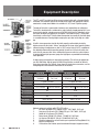
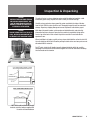
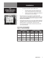
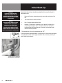
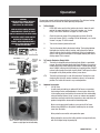
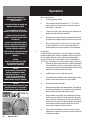
KTT/KTC-E
Series
KTT-E Series
ELECTRIC TABLE TOP TILTING KETTLE
INSTALLATION – OPERATION – MAINTENANCE
BLODGETT OVEN COMPANY
BLODGETT OVEN COMPANY
www.blodgett.com
www.blodgett.com
44 Lakeside Avenue,
Burlington, Vermont 05401 USA
44 Lakeside Avenue, Burlington, Vermont
05401 USA
Telephone
(800)
331-5842, (802) 860-3700 Fax: (802) 864-0183
Manufacture
Service
Questions:
866-518-3977
1 A (5/04)
S00063 170000
Rev
PART NUMBER
REV B (04/11)
THIS MANUAL MUST BE RETAINED FOR FUTURE REFERENCE. READ, UNDERSTAND
AND FOLLOW THE INSTRUCTIONS AND WARNINGS CONTAINED IN THIS MANUAL.
FOR YOUR SAFETY
Do not store or use gasoline or other flammable vapors and liquids in
the vicinity of this or any other appliance.
WARNING
Improper installation, adjustment, alteration, service or maintenance can
cause property damage, injury or death. Read the installation, operating
and maintenance instructions thoroughly before installing or servicing
this equipment.
NOTIFY CARRIER OF DAMAGE AT ONCE
It is the responsibility of the consignee to inspect the container upon
receipt of same and to determine the possibility of any damage, including
concealed damage. WE suggest that if you are suspicious of damage to
make a notation on the delivery receipt. It will be the responsibility of the
consignee to file a claim with the carrier. We recommend that you do so
at once.
IMPORTANT - READ FIRST - IMPORTANT
CAUTION: BE SURE ALL OPERATORS READ, UNDERSTAND AND FOLLOW THE OPERATING INSTRUCTIONS,
CAUTIONS, AND SAFETY INSTRUCTIONS CONTAINED IN THIS MANUAL.
WARNING: THIS UNIT IS INTENDED FOR USE IN THE COMMERCIAL HEATING, COOKING AND HOLDING OF
WATER AND FOOD PRODUCTS, PER THE INSTRUCTIONS CONTAINED IN THIS MANUAL. ANY OTHER
USE COULD RESULT IN SERIOUS PERSONAL INJURY OR DAMAGE TO THE EQUIPMENT AND WILL
VOID WARRANTY.
WARNING: KETTLE MUST BE INSTALLED BY PERSONNEL QUALIFIED TO WORK WITH ELECTRICITY. IMPROPER
INSTALLATION CAN RESULT IN INJURY TO PERSONNEL AND/OR DAMAGE TO EQUIPMENT.
DANGER: ELECTRICALLY GROUND THE UNIT AT THE TERMINAL PROVIDED. FAILURE TO GROUND UNIT
COULD RESULT IN ELECTROCUTION AND DEATH.
WARNING: AVOID ALL DIRECT CONTACT WITH HOT EQUIPMENT SURFACES. DIRECT SKIN CONTACT COULD
RESULT IN SEVERE BURNS.
WARNING: AVOID ALL DIRECT CONTACT WITH HOT FOOD OR WATER IN THE KETTLE. DIRECT CONTACT
COULD RESULT IN SEVERE BURNS.
CAUTION: DO NOT OVER FILL THE KETTLE WHEN COOKING, HOLDING OR CLEANING. KEEP LIQUIDS A
MINIMUM OF 2-3” (5-8 cm) BELOW THE KETTLE BODY RIM TO ALLOW CLEARANCE FOR STIRRING,
BOILING AND SAFE PRODUCT TRANSFER.
WARNING: TAKE SPECIAL CARE TO AVOID CONTACT WITH HOT KETTLE BODY OR HOT PRODUCT WHEN
ADDING INGREDIENTS, STIRRING OR TRANSFERRING PRODUCT TO ANOTHER CONTAINER.
WARNING: DO NOT STAND ON OR APPLY UNNECESSARY WEIGHT OR PRESSURE ON THE KETTLE FRONT OR
POURING LIP. THIS COULD RESULT IN OVERLOAD AND FAILURE OF THE TILT MECHANISM, AND
POSSIBLE SERIOUS INJURY AND BURNS TO THE OPERATOR AND OTHERS.
WARNING: WHEN TILTING KETTLE FOR PRODUCT TRANSFER:
1) WEAR PROTECTIVE OVEN MITT AND PROTECTIVE APRON.
2) USE CONTAINER DEEP ENOUGH TO CONTAIN AND MINIMIZE PRODUCT SPLASHING.
3) PLACE CONTAINER ON STABLE, FLAT SURFACE, AS CLOSE TO KETTLE AS POSSIBLE.
4) STAND TO LEFT OR RIGHT SIDE OF KETTLE (DEPENDING ON TILTING HANDLE PLACEMENT)
WHILE POURING . DO NOT STAND DIRECTLY IN POUR PATH OF HOT CONTENTS.
5) POUR SLOWLY, MAINTAIN CONTROL OF KETTLE BODY HANDLE AT ALL TIMES, AND RETURN
KETTLE BODY TO UPRIGHT POSITION AFTER CONTAINER IS FILLED OR TRANSFER IS COMPLETE.
6) DO NOT OVER FILL CONTAINER. AVOID DIRECT SKIN CONTACT WITH HOT CONTAINER AND ITS
CONTENTS.
CAUTION: KEEP FLOORS IN FRONT OF KETTLE WORK AREA CLEAN AND DRY. IF SPILLS OCCUR, CLEAN
IMMEDIATELY, TO AVOID SLIPS OR FALLS.
WARNING: FAILURE TO CHECK PRESSURE RELIEF VALVE OPERATION PERIODICALLY COULD RESULT IN
PERSONAL INJURY AND/OR DAMAGE TO EQUIPMENT.
OM-KTT/KTC-E
1
IMPORTANT - READ FIRST - IMPORTANT
WARNING: WHEN TESTING, AVOID ANY EXPOSURE TO THE STEAM BLOWING OUT OF THE PRESSURE RELIEF
VALVE. DIRECT CONTACT COULD RESULT IN SEVERE BURNS.
WARNING: TO AVOID INJURY, READ AND FOLLOW ALL PRECAUTIONS STATED ON THE LABEL OF THE WATER
TREATMENT COMPOUND.
WARNING: BEFORE REPLACING ANY PARTS, DISCONNECT THE UNIT FROM THE ELECTRIC POWER SUPPLY.
WARNING: KEEP WATER AND SOLUTIONS OUT OF CONTROLS AND ELECTRICAL EQUIPMENT. NEVER USE A
HIGH PRESSURE HOSE TO CLEAN KETTLE SURFACES.
CAUTION: MOST CLEANERS ARE HARMFUL TO THE SKIN, EYES, MUCOUS MEMBRANES AND CLOTHING.
PRECAUTIONS SHOULD BE TAKEN. WEAR RUBBER GLOVES, GOGGLES OR FACE SHIELD AND
PROTECTIVE CLOTHING. CAREFULLY READ THE WARNINGS AND FOLLOW THE DIRECTIONS ON THE
LABEL OF THE CLEANER TO BE USED.
CAUTION: USE OF ANY REPLACEMENT PARTS OTHER THAN THOSE SUPPLIED BY BLODGETT OR THEIR
AUTHORIZED DISTRIBUTORS CAN CAUSE OPERATOR INJURY AND DAMAGE TO THE EQUIPMENT,
AND WILL VOID ALL WARRANTIES.
IMPORTANT: SERVICE PERFORMED BY OTHER THAN FACTORY AUTHORIZED PERSONNEL WILL VOID
WARRANTIES.
WARNING: DO NOT HEAT AN EMPTY KETTLE. EXCESSIVE STEAM PRESSURE COULD DEVELOP.
2
OM-KTT/KTC-E
Table of Contents
Important Operator Warnings ....................................................page 1-2
References.................................................................................... page 3
Equipment Description.................................................................. page 4
Inspection and Unpacking ............................................................ page 5
Installation .................................................................................. page 6-7
Initial Start-Up............................................................................... page 8
Operation ................................................................................ page 9-10
Sequence of Operation ............................................................... page 11
Cleaning................................................................................... page 12-13
Maintenance............................................................................ page 14-15
Troubleshooting............................................................................ page 16
Wiring Diagram ............................................................................ page 21
Service Log ........................................................................... page 22-23
References
KLENZADE SALES CENTER ECOLAB. Inc.
370 Wabasha
St. Paul, Minnesota 55102
800/352-5326 or 612/293-2233
NATIONAL FIRE PROTECTION ASSOCIATION
60 Battery March Park
Quincy, Massachusetts 02269
NFPA/70 - The National Electrical Code
NSF INTERNATIONAL
789 N. Dixboro Road
P.O. Box 130140
Ann Arbor, Michigan 48113-0140
UNDERWRITERS LABORATORIES, INC.
333 Pfingsten Road
Northbrook, Illinois 60062
ZEP MANUFACTURING CO.
1310-T Seaboard Industrial Blvd.
Atlanta, Georgia 30318
OM-KTT/KTC-E
3
Equipment Description
The KTT and KTC are table top, tilting, steam jacketed kettles with a thermostatically
controlled, self-contained, electrically-heated steam supply and appropriate controls,
mounted on a sturdy base. Models are available in 5, 6, 10 and 12-gallon capacity.
The body of the kettle is constructed of stainless steel, welded into one solid piece.
The kettle is furnished with a reinforced rim and a butterfly shaped pouring lip. It has a
steam jacket rated for a design pressure of 50 PSIG. Kettle finish is 180 emery grit on
the inside and bright semi-deluxe on the outside. A tilt handle on the KTT kettle and a
hand wheel crank on the KTC kettle allows the operator to manually tilt the kettle body
in a controlled manner. Pouring height accepts pans up to four inches high on a table
top.
Model KTT
A built-in steam generator, sized for the kettle capacity and heated by electricity,
delivers steam into the jacket. “Airless” operation of the steam jacket permits uniform,
efficient heating at temperatures as low as 150°F and as high as 295°F. In addition to
the adjustable thermostat for operating control, the unit has a tilt cut-off switch, low
water cut-off, pressure relief valve, and high-limit pressure switch as safety features.
A heating indicator light, pressure gauge, and sight glass are provided for monitoring
kettle operation.
Model KTC
A single electrical connection is required for installation. The unit may be ordered for
use with 208/240 or 480 volt power. All 208/240 volt kettles are wired for 208 volt,
three-phase operation. For 240 volt, three-phase OR single-phase conversion, see the
wiring diagrams and installation instructions in this manual.
KETTLE CHARACTERISTICS
Description
Kettle Capacity
5E-KTT/KTC
6E-KTT/KTC
10E-KTT/KTC
12E-KTT/KTC
5 gal (20 qt) /
18.9 liter
6 gal (24 qt) /
22.7 liter
10 gal (40 qt) /
37.8 liter
12 gal (48 qt) /
45.4 liter
Jacket Capacity
7 quart / 6.6 liter
9 quart / 8.5 liter
Inside Diameter
14 in / 36 cm
16-1/2 in / 42 cm
Depth
11 in / 28 cm
12.5 in / 32 cm
14-1/4 in / 36 cm 16-1/2 in / 42 cm
kW at 208 Volts
6.3
10.8
kW at 240 Volts
8.4
14.4
kW at 480 Volts
6.3
12.0
Base Width
24 in / 61 cm
28 in / 71 cm
Base Depth
16 in / 41 cm
16 in / 41 cm
Optional equipment available with KTT & KTC kettles:
1. Kit, cover and holder (P/N 170090, 5/6 gal - P/N 170042, 10/12 gal).
2. One-piece, lift-off cover (P/N 170089, 5/6 gal - P/N 170041, 10/12 gal).
3. Holder for Lift-off cover (P/N 133837).
4. Basket insert (P/N 001159, 5/6 gal - P/N 001161, 10/12 gal).
5. Lip Strainer (P/N 005187, 5/6 gal - P/N 005186, 10/12 gal).
Stand that supports the unit and holds a pan in position for filling (Model S-18).
6. 7. Water fill swing faucet.
8. 316 stainless steel interior (must be ordered with original equipment order).
4
OM-KTT/KTC-E
Inspection & Unpacking
CAUTION
SHIPPING STRAPS ARE UNDER TENSION
AND CAN SNAP BACK WHEN CUT. TAKE
CARE TO AVOID PERSONAL INJURY OR
DAMAGE TO THE UNIT BY STAPLES LEFT
IN THE WALLS OF THE CARTON.
The unit will arrive in a heavy shipping carton and will be bolted or banded to a skid.
Immediately upon receipt, inspect the carton carefully for exterior damage.
CAUTION
THIS UNIT WEIGHS 140 TO 163 LBS (64 TO
74 KG). INSTALLER SHOULD OBTAIN HELP
AS NEEDED TO LIFT THIS WEIGHT SAFELY.
Write down the model number, serial number, and installation date, and retain this
information for future reference. Space for these entries is provided at the top of the
Service Log at the back of this manual. Keep this manual on file and available for
operators to use.
Carefully cut any polyester straps around the carton and detach the sides of the box
from the skid. Pull the carton up off the unit. Thoroughly inspect the unit for concealed
damage. Report any shipping damage or incorrect shipments to the delivery agent.
When installation is to begin, carefully cut any straps which hold the unit on the skid. Lift
the unit straight up off the skid. Examine packing materials to be sure loose parts are not
discarded with the materials.
For KTT units, attach the tilt handle (normally shipped inside the kettle) by carefully
threading it into the socket on the trunnion support. Be careful to avoid cross-threading
the fine threads on the trunnion.
NOTE: After handle installation on the right
hand side, retain the hardware supplied with
the unit for left hand installation.
OM-KTT/KTC-E
5
Installation
WARNING
INSTALLATION OF THE KETTLE MUST BE
DONE BY A CERTIFIED ELECTRICIAN OR
AUTHORIZED REPRESENTATIVE QUALIFIED
TO WORK WITH ELECTRICITY. IMPROPER
INSTALLATION CAN RESULT IN INJURY TO
PERSONNEL AN/OR DAMAGE
TO EQUIPMENT.
CAUTION
BEFORE ANY ELECTRICAL CONVERSION,
VERIFY THAT THE BRANCH CIRCUIT
WIRING IS ADEQUATE TO HANDLE ANY
INCREASE AMPERAGE REQUIREMENTS.
REFER TO THE ELECTRICAL
SPECIFICATIONS LISTED BELOW.
The KTT/KTC Kettle is provided with complete internal wiring and is ready for
immediate connection. Wiring diagrams are provided in this manual and on the inside
of the control housing service panel. Any mechanical or electrical changes must be
approved by Blodgett’s Engineering Department.
The completed unit has been operated at the factory to test all controls and heater
elements.
1. Set the kettle in place and level it. The base should be securely fastened to a
table or work surface. Four 3/8”-16 N.C. threaded couplings are provided in the
base of unit. Installation under a ventilation hood is recommended.
2. Once the unit is anchored to a mounting surface, apply a small bead of silicone
caulk around the perimeter of the kettle base and seal the joint.
3.
Provide electrical power as specified on the electrical information plate
attached to the equipment. Observe local codes and/or The National Electrical
Code in accordance with ANSI/NFPA 70 - (current edition).
4. Standard equipment is shipped ready for 208V, 3-phase or 480V, 3-phase
operation. Refer to the wiring diagram located on the inside cover of the
control box and the instructions below for conversion to single-phase
operation. A jumper wire and “conversion” label are included with the unit.
They can be found in a plastic bag attached to the trunnion assembly inside
the control box.
a. b. 6
OM-KTT/KTC-E
For conversion from 208V, 3-phase to 208V or 240V 1-phase or
480V, 3-phase to 480V, 1-phase:
i. Verify that the branch circuit wiring is adequate for any
increased amperage requirements (see table on page 8).
ii. For 240V 1-phase only, enlarge electrical inlet opening for
1” conduit fitting. Use a 1” sealtite conduit fitting.
iii. Refer to wiring diagram for field conversion.
iv. For 240V 1-phase only, pull lead from 208V tab on control
transformer and insert on 240V tab (See photo on page 8).
v. Complete “conversion label” (supplied in bag) and adhere it
to the control box near the UL dataplate.
For conversion from 208V, 3-phase to 240V, 3-phase:
i. Verify that the branch circuit wiring is adequate for any
increased amperage requirements (see table on page 8).
ii. Pull lead from 208V tab on control transformer and insert
on 240V tab. (See photo on page 8)
iii. Complete “conversion label” (supplied in bag and adhere it
to the control box near the UL dataplate).
Installation
DANGER
ELECTRICALLY GROUND THE UNIT AT
THE TERMINAL PROVIDED. FAILURE TO
GROUND UNIT COULD RESULT IN
ELECTROCUTION AND DEATH.
Pull lead from 208V tab and insert on 240V tab.
c. For conversion from 480V, 3-phase to 460V, 3-phase:
i. Verify that the branch circuit wiring is adequate for any
increase amperage requirements (see table on page 8).
ii. Complete “conversion label” (supplied in bag and adhere it
to the control box near the UL dataplate).
5. Bring incoming electrical service through the conduit fitting (for 240V
1-phase, a new one inch conduit fitting is required) at the rear of the support
housing, making a watertight connection with the incoming lines. A BX style
connection is not recommended.
6. Confirm that the jacket water level is at or just above mid point of sight glass
(new models). If the level is low, follow the instructions under “Jacket Filling
and Water Treatment” in the “Maintenance” section of the manual.
7. Ensure that the open end of the elbow on the outlet of the pressure relief
valve is directed downward.
KTT/KTC SUPPLY WIRE REQUIREMENTS
THWN (75°) / THHN (90°) COPPER ONLY
5E/6E-KTT, 5E/6E-KTC
10E/12E-KTT, 10E/12E-KTC
AMPS
SUPPLY
WIRE
208V 1 PH
3 PH
31
18
8
12
240V 1 PH
3 PH
35
20
460V 3 PH
480V 1 PH
3 PH
VOLTAGE
AMPS
SUPPLY
WIRE
208V 1 PH
3 PH
52
30
6
8
8
12
240V 1 PH
3 PH
60
35
4
8
7.3
14
460V 3 PH
14
12
14
8
14
14
480V 1 PH
3 PH
25
15
10
12
VOLTAGE
OM-KTT/KTC-E
7
Initial Start-Up
IMPORTANT
BE SURE ALL OPERATORS READ,
UNDERSTAND AND FOLLOW THE
OPERATING INSTRUCTIONS, CAUTIONS
AND SAFETY INSTRUCTIONS CONTAINED
IN THIS MANUAL.
WARNING
AVOID ALL DIRECT CONTACT WITH HOT
SURFACES. DIRECT SKIN CONTACT
COULD RESULT IN SEVERE BURNS.
AVOID ALL DIRECT CONTACT WITH HOT
FOOD OR WATER IN THE KETTLE. DIRECT
CONTACT COULD RESULT IN SEVERE BURNS.
Now that the kettle has been installed, you should test it to ensure that the unit is
operating correctly.
1. Remove all literature and packing materials from inside and outside of the
unit.
2. Turn on the electrical service to the unit.
3. Pour 1-2 quarts of water into the kettle.
4. Following “To Start Kettle” instructions in the “Operation” section of this
manual, begin heating the water at the highest thermostat setting. The
heating indicator light should come on immediately, and heating should
continue until the water boils.
5. To shut down the unit, turn the thermostat dial to “OFF”.
If the unit functions as described above, it is ready for use. If the unit does not function
as intended, first recheck power supply connections and, if necessary, contact your
local Certified Service Agency.
A simple turn of the thermostat
controls the KTT and KTC kettle.
8
OM-KTT/KTC-E
Operation
WARNING
AVOID ALL DIRECT CONTACT WITH HOT
SURFACES. DIRECT SKIN CONTACT
COULD RESULT IN SEVERE BURNS.
The operator controls kettle heating with the thermostat dial. The dial turns heating
element power on or off and sets the kettle operating temperature.
A. AVOID ALL DIRECT CONTACT WITH HOT
FOOD OR WATER IN THE KETTLE. DIRECT
CONTACT COULD RESULT IN SEVERE BURNS.
TAKE SPECIAL CARE TO AVOID CONTACT
WITH HOT KETTLE BODY OR HOT
PRODUCT, WHEN ADDING INGREDIENTS,
STIRRING OR TRANSFERRING PRODUCT
TO ANOTHER CONTAINER.
B. Model KTT
On KTT and KTC units, the jacket water level is
shown in a sight glass on the kettle body.
2. Check the pressure gauge. If the gauge does not show 20 to 30
inches of vacuum (that is, a reading of 20 to 30 below 0), see “Jacket
Vacuum” on page 15 of this manual.
3. Turn on the electrical power to the unit.
4. Turn the thermostat dial to the desired setting. The heating indicator
light indicates that the kettle is heating, and cycling of the light on
and off indicates that the kettle is being held at the set temperature.
Once in each cycle the contactors in the support housing will make a
clicking sound. This is normal.
To Transfer Product or Empty Kettle
KTT: The kettle is designed and manufactured to be tilted in a controlled
manner. Grasp the insulated plastic ball firmly. Maintain a firm grip on
handle when tilting, while keeping kettle body in a tilted position and
when SLOWLY returning the kettle body to an upright position. DO NOT
release kettle handle when kettle is partly tilted. It will impact in either
the upright or fully tilted position and may cause burns.
KTC: C. Model KTC
To Start Kettle
1.
EVERY DAY make sure that the jacket water level is above the midpoint of the round sight glass. If the level is too low, see “Jacket
Filling” and “Water Treatment” on page 16 of this manual.
The kettle is tilted using its crank tilt hand wheel. Turning the crank
clockwise tilts the kettle; counter-clockwise returns it to an upright
position. The kettle will remain in any cranked position.
Common Accessories
1.
Lift-Off Cover
As with stock pot cooking, an optional lift off cover can speed up
the heating of water and food products. A cover helps retain heat
in the cooking vessel and reduces the amount of heat and humidity
released into the kitchen. Use of a cover can reduce some product
cook times and help maintain the temperature, color and texture of
products being held or simmered for extended periods.
Make sure the plastic ball handle is secure on the lift off cover
before using. ALWAYS use the plastic handle to place or remove
cover from the kettle.
Wear protective oven mitts and a protective apron.
When putting the cover on the kettle, position it on top of kettle rim,
with its flat edge facing the pouring lip.
OM-KTT/KTC-E
9
Operation
WARNING WHEN TILTING KETTLE
1) WEAR PROTECTIVE OVEN MITT AND
PROTECTIVE APRON.
2) USE DEEP CONTAINER TO CONTAIN AND
MINIMIZE PRODUCT SPLASHING.
3) PLACE CONTAINER ON STABLE, FLAT
SURFACE, AS CLOSE TO KETTLE AS POSSIBLE.
4) STAND TO RIGHT OF KETTLE WHILE
POURING—NOT DIRECTLY IN POUR PATH OF
HOT CONTENTS.
5) POUR SLOWLY, MAINTAINING CONTROL
OF KETTLE, AND RETURN KETTLE BODY TO
UPRIGHT POSITION AFTER CONTAINER IS
FILLED OR TRANSFER IS COMPLETE.
6) DO NOT OVERFILL CONTAINER. AVOID SKIN
CONTACT WITH HOT CONTAINER AND ITS
CONTENTS.
CAUTION
DO NOT TILT KETTLE BODY WITH COVER
IN PLACE. COVER MAY SLIDE OFF,
CAUSING INJURY TO OPERATOR.
CAUTION
DO NOT OVERFILL THE KETTLE WHEN
COOKING, HOLDING OR CLEANING.
KEEP LIQUIDS AT LEAST 2-3” (5-8 cm)
BELOW THE KETTLE BODY RIM TO
ALLOW CLEARANCE FOR STIRRING,
BOILING PRODUCT AND SAFE TRANSFER.
CAUTION
KEEP FLOORS IN FRONT OF THE KETTLE WORK
AREA CLEAN AND DRY. IF SPILLS OCCUR,
CLEAN AT ONCE TO AVOID SLIPS OR FALLS.
10
OM-KTT/KTC-E
2.
When removing cover:
a.
Firmly grasp plastic handle
b. Lift rear edge (farthest from operator) 1- 2” (3-5 cm) to
allow any steam and water vapor to escape the cooking
vessel. Wait 2-3 seconds.
c. Tilt cover to 45-60° angle and allow any hot condensate or
product to roll off cover back into kettle.
d.
Remove cover, ensuring that any remaining hot condensate
or product does not drip on operator, floor or work surfaces.
e.
Place cover on safe, flat, sanitary, out-of-the-way surface,
or return to kettle rim. Cover may also be placed in the
optional holder for the cover as shown in the photograph.
Basket Insert
An optional kettle basket insert can assist in cooking water-boiled
products including eggs, potatoes, vegetables, shell fish, pasta and
rice. The nylon mesh liner must be used when cooking product
smaller than the mesh size of the basket, which is approximately
1/4” (6 mm). This includes rice and small pasta shapes. Tips for use:
a.
Allow for the water displacement of the basket and product
to be cooked. This may mean only filling the kettle half full
of water. Test the basket and product displacement with the
kettle OFF, and with cold water in the kettle.
b.
Load baskets on a level, stable work surface.
c.
Lift loaded baskets with both hands. Get help from another
person if the basket is too heavy for safe handling.
d.
Slowly lower product into kettle.
e.
When removing baskets with cooked product, lift straight up,
ensuring basket bottoms clear the kettle rim and pouring lip.
Wear protective oven mitts and protective apron.
f.
Allow hot water to fully drain from product before moving
basket away from the kettle. Do not rest baskets on kettle
rim or pouring lip. If baskets are too heavy for individual to
lift and safely move, get help. Remove product immediately
from basket into another container, being sure to avoid
contact with hot product and hot basket or...
g.
Place baskets with food on a stable, flat surface, inside a
solid steamer or bake pan,to catch any remaining hot water
draining from product.
Sequence of Operation
The following “action-reaction” outline is provided to help understand how the kettle
works.
When the operator starts up the kettle by turning the operating thermostat dial from
“OFF” to a desired setting, the thermostat switch closes. This lights up the heating
indicator light and causes the contactors to close, allowing power to flow to the
heating elements. When the temperature of the steam jacket reaches the value
corresponding to the dial setting, the thermostat switch opens. This turns off the
heating indicator light and causes the contactors to open, stopping the power to
the heaters. As soon as the thermostat senses that the kettle is cooling below the
set point, the thermostat switch closes, the heating indicator light comes on, the
contactors close, and the heaters come on again. On-off cycling continues, keeping
the kettle at the set temperature. This is why the heating indicator light cycles on
and off during normal operation. Every time the kettle is tilted, the tilt cut-off switch
interrupts the power supply to the heaters, so that the heating elements will not
operate while not submerged in the jacket water.
If steam pressure greater than 50 PSI is generated in the jacket, the pressure relief
valve will open and relieve the excess pressure.
In the event that the jacket water level gets too low and the heating elements
overheat, the high limit control will open and shut off power to the elements until the
kettle cools. Setting the operating thermostat dial to “OFF” shuts down all control and
heating circuits.
OM-KTT/KTC-E
11
OM-TD
OM-TD
another container, being sure to avoid
contact with hot product and hot basket
or. . .
Cleaning
OM-TD
Place basket with food on stable, flat
WARNING
Suggested Cleaning Supplies:
surface, setting it inside a solid steamer 1. another
container,
being
avoid
KEEP
WATER
SOLUTIONS
OUTsure
OF tohot
a. Cleaner, such as Klenzade HC-10 or HC-32 from ECOLAB, Inc.
or bake
pan,AND
to catch
any
remaining
contact
hot
product
hot basket
CONTROLS
ANDwith
ELECTRICAL
EQUIPMENT.
b. Kettle brushes in good condition.
water
which
might
drain
from and
product.
or.USE
. . A HIGH PRESSURE HOSE TO
DO NOT
c. Sanitizer such as Klenzade XY-12.
CLEAN THE CONTROL CONSOLE,
d. Film remover such as Klenzade LC-30.
f) ELECTRICAL
Place basket
with food ETC.
on stable, flat
CONNECTIONS,
surface, setting it inside a solid steamer
2. Precautions
g
or bake pan,
to catch any remaining hot
CAUTION
Before any cleaning operation, shut off the kettle by turning the thermostat
mightSANITIZER
drain from
NEVERwater
LEAVEwhich
A CHLORINE
IN product.
dial to “OFF”, and shut off all electric power to the unit at a remote switch,
c. Prepare
a hot
solution
of the
detergent/
CONTACT
WITH
STAINLESS
STEEL
such as the circuit breaker.
cleaning
compound
as instructed
SURFACES
FOR LONGER
THAN 30 by the
supplier.
MINUTES. LONGER CONTACT CAN
3. Procedure
ing
a. Clean food contact surfaces as soon as possible after use, preferably CAUSE CORROSION.
f)
OM-TD
c.
Prepare WARNING
a hot solution of the detergent/
AVOID
DIRECTcompound
CONTACT WITH
HOT
cleaning
as instructed
by the
b. SURFACES.
supplier.DIRECT SKIN CONTACT
COULD RESULT IN SEVERE BURNS.
Use brushes, sponges or cloth to clean your
kettles
Prepare a solution of the detergent/cleaning compound as
instructed by the supplier. Clean the unit thoroughly. A cloth
moistened with cleaning solution can be used to clean controls, housing, electrical conduit, etc.
Rinse the kettle thoroughly with hot water. Then drain completely.
d. e.
g. Don’t scrape with tools, steel wool or other
abrasives.
d.
Clean the unit thoroughly, inside and
outside.
Don’t
scrape
steel wool
e.
Rinse
the with
kettletools,
thoroughly
with or
hotother
abrasives.
water, then drain completely.
12
d.
Scrape and flush out large amounts of food residues. Be careful not to scratch the kettle with metal implements.
c. f. Use a brush, sponge, cloth, plastic or
rubber scraper, or plastic wool to clean. Use brushes, sponges or cloth to clean your
kettles
Don’t use metal implements
or steel wool when cleaning.
while the kettle is still warm. If the unit is in continuous use, clean and sanitize inside and outside at least once every 12 hours.
Clean the unit thoroughly, inside and
OM-KTT/KTC-E
outside.
As part of the daily cleaning program, clean all inside and outside surfaces that may have been soiled. Remember to check such parts as the underside of the cover, control housing, etc.
To remove burned-on foods, use a brush, sponge, cloth, plastic or rubber scraper, or plastic wool along with the cleaning solution. To reduce effort required in washing, let the detergent solution sit in the kettle for a few minutes and soak into the residue. Do NOT use abrasive materials or metal tools that might scratch the surface.
Scratches make the surface harder to clean and provide places for bacteria to grow. Do not use steel wool, which will leave particles in the surface and cause eventual corrosion and pitting.
The outside of the unit may be cleaned with a warm water (100°F or less) spray. Do not use a high pressure spray.
Cleaning
CAUTION
MOST CLEANERS ARE HARMFUL TO THE
SKIN, EYES, MUCOUS MEMBRANES AND
CLOTHING. PRECAUTIONS SHOULD BE
TAKEN TO WEAR RUBBER GLOVES,
GOGGLES OR FACE SHIELD AND
PROTECTIVE CLOTHING. CAREFULLY
READ THE WARNINGS AND FOLLOW
LABEL DIRECTIONS.
h. The outside of the unit may be polished with a recognized
stainless steel cleaner like Zepper from Zep Manufacturing
Company.
i. When the equipment needs to be sanitized, use a sanitizing solution equivalent to one that supplies 200 parts per
million chlorine. Obtain advice on the best sanitizing agent
from your supplier of sanitizing products. Following the
supplier instructions, apply the sanitizing agent after the
unit has been cleaned and drained. Rinse off the sanitizer
thoroughly.
j. It is recommended that the unit be sanitized just before use.
k. Clean the kettle thoroughly. If there is difficulty
removing mineral deposits or a film left by hard water
or food residues, then use a de-liming agent, following
manufacturer directions.
l. Rinse and drain the unit thoroughly before further use.
m. If especially difficult cleaning problems persist, contact your
cleaning product supplier for assistance. The supplier has a
trained technical staff with laboratory facilities to serve you.
OM-KTT/KTC-E
13
Maintenance
WARNING
AVOID ANY EXPOSURE TO THE STEAM
BLOWING OUT OF THE PRESSURE
RELIEF VALVE. SEVERE BURNS CAN
RESULT ON EXPOSED SKIN.
FAILURE TO CHECK PRESSURE RELIEF
VALVE OPERATION PERIODICALLY
COULD RESULT IN PERSONAL INJURY
AND/OR DAMAGE TO EQUIPMENT.
NOTICE: Contact an authorized representative when repairs are required.
A Maintenance & Service Log is provided at the back of this manual. Each time
maintenance is performed on your kettle, enter the date on which the work was done,
what was done, and who did it. Keep this manual on file and available for operators to
use. Periodic inspection will minimize equipment down time and increase the efficiency
of operation. The following points should be checked:
1.
Jacket Vacuum/Removing Air from Jacket (by Operator)
Every day, while the kettle is cold, read the pressure/ vacuum gauge. A
positive reading or a negative reading between zero and 20” vacuum on the
pressure/ vacuum gauge indicates excess air in the jacket. Air in the jacket
slows kettle heating and can prevent the kettle from reaching operating
temperature. To remove air:
To remove air:
a.
Start the unit. (See “Operation” section).
CAUTION
KEEP GREASE AWAY FROM ELECTRICAL
PARTS LOCATED NEAR THE GEARS.
Make sure that the
open end of the elbow
on the pressure
relief valve is directed
downward.
14
OM-KTT/KTC-E
The pressure gauge
should show a 2.
vacuum of 20 to 30 inches when the
kettle is cold.
b.
Make sure the elbow on the outlet of the pressure relief valve is turned
so that escaping steam is directed down toward the floor. Be sure and
follow the instructions on the attached pressure relief valve tag.
c.
When the pressure/vacuum gauge reaches a positive pressure reading
of 5 PSI, release trapped air by lifting the pressure relief valve ring
for about one second. Repeat this step, then let the valve ring snap
closed, so the valve will seat properly and not leak.
Pressure Relief Valve (by Operator)
At least twice a month, test the pressure relief valve. Test the valve with the
kettle operating at 15 PSI (105 kPa), by holding the test ring for at least five
seconds. Then release the ring and permit the valve to snap shut. If the ring
does not activate, if there is no discharge, or if the valve leaks, stop using the
kettle immediately and contact a authorized service representative.
3.
Grease / Lubrication (by Service)
KTT Models: At least twice a year, grease the two trunnion bearings. The
bearings are located within the kettle support housing. Remove the access
panels from the support housing with a screwdriver to gain access to the
grease fittings. Use a lithium-based, multi-purpose grease. When the access
panels are removed, the mounting bolts for the trunnion bearings and tilt
switch can also be checked for tightness. When finished, reassemble access
panels to support housing.
KTC Models: The gear housing has been fitted for proper lubrication of
moving parts. Since the gears do not run in oil, periodic lubrication with
grease is essential. Frequency of lubrication depends on operating conditions,
but should occur at least once every six months. The use of a Number Two
grade LGI lithium grease is recommended. Add grease through the Zerk
fittings on the gear housing until grease flows out of the bearings around the
trunnion shaft. Place a liberal amount of grease on the gear to cover the arc
that is in contact with the worm gear.
Maintenance
WARNING
TO AVOID INJURY, READ AND FOLLOW
ALL PRECAUTIONS STATED ON THE
LABEL OF THE WATER TREATMENT
COMPOUND.
4.
Jacket Filling
Every day, before you turn on the unit, make sure the water level is
approximately in the center of the water gauge glass. The jacket was filled at
the factory with the proper amount of treated water, and is airtight, but over
time steam may be vented and water lost.
From time to time, you may need to restore the water to its proper level. The
procedure for adding water follows.
The pressure relief valve and fill
plug are located directly behind the
pressure/vacuum gauge.
5.
a.
If you are replacing water lost as steam, use distilled water. Do not use
tap water. If you are replacing treated water that was drained from the
jacket, prepare more treated water as directed below.
b.
Allow the kettle to cool completely. Remove the pipe plug from the
jacket fill assembly. Pour in the distilled or treated water. Using a
funnel will help you in this process. Hold the pressure relief valve open
while you pour, to let air escape from the jacket. Continue adding
water until the water level rises to the center of the round sight glass.
c. Air that gets into the jacket during the filling operation must be
removed, because it will make heating less efficient. Follow the
procedure in Jacket Vacuum/Removing Air From Jacket above, to
restore a negative pressure reading.
Water Treatment
a.
Fill a mixing container with the amount of water required. Use only
distilled water.
Model
Kettle Capacity
5E-KTT, 5E-KTC
5 gal (20 qt) 18.9 liter
7 quart
6.6 liter
6E-KTT, 6E-KTC
6 gal (24 qt ) 22.7 liter
7 quart
6.6 liter
10E-KTT, 10E-KTC
10 gal (40 qt) 37.8 liter
9 quart
8.5 liter
12E-KTT, 12E-KTC
12 gal (48 qt) 45.4 liter
9 quart
8.5 liter
Jacket Capacity
b. Hang a strip of pH test paper on the rim of the container, with about 1
inch of the strip below the surface of the water.
c. Stir the water continuously, while you slowly add water treatment
compound until a color between indicating a pH of 10.5 and 11.5 is
reached. (Shown on the pH test kit chart.) Judge the pH by frequently
comparing the test strip with the color chart provided in the pH test kit.
If there is a problem distinguishing color, use a pH meter.
d. Use a measuring cup to add the compound so that you may record the
exact amount used.
e. The amount may be used again, if the same water sources and
compound are used in the future. However, it is best to check the pH
each time treated water is prepared.
OM-KTT/KTC-E
15
Troubleshooting
Your kettle is designed to operate smoothly and efficiently if properly maintained. However, the following is a list of checks to make
in the event of a problem. Wiring diagrams are furnished inside the service panel. X indicates items which must be performed by
an authorized technician. USE OF ANY REPLACEMENT PARTS OTHER THAN THOSE SUPPLIED BY THE MANUFACTURER OR AN
AUTHORIZED DISTRIBUTOR CAN CAUSE INJURY TO THE OPERATOR AND DAMAGE TO THE EQUIPMENT AND WILL VOID ALL
WARRANTIES.
SYMPTOM
Kettle is hard to tilt.
(KTC only)
Kettle will not heat, and
heating indicator will not
come on.
Kettle will not heat, but
heating indicator comes
on.
Kettle continues heating
after it reaches the
desired temperature.
Kettle stops heating
before it reaches the
desired temperature.
Kettle heats slowly.
WHO
WHAT TO CHECK
Authorized
a. Gears for foreign materials, and lubrication. X
Service Rep Only b. Gears for alignment. X
c. Worn gears or broken gears. X
User
a. Electric power supply to the unit. (Check the circuit breaker.)
b. Water level in jacket.
Authorized
c. Control circuit fuses. Replace a blown fuse only with a fuse of
Service Rep Only the same AMP rating. X
d. For loose or broken wires. X
e. Tilt cut-off switch. X
f. That pressure switch is open. X
g. Operation of variable thermostat. X
h. Low water cutoff. X
Authorized
a. Thermostat calibration. X
Service Rep Only b. Heater elements with ohmmeter for ground short or open
element. If element is defective, call service. X
User
a. Thermostat dial setting.
Authorized
b. Thermostat circuit for short. X
Service Rep Only c. Thermostat operation. The thermostat should click when the
dial is rotated above and below the setting for the temperature
of the kettle. X
d. Contactor, to determine whether it is energized or stuck. X
User
a. Thermostat dial setting.
Authorized
b. Thermostat calibration. X
Service Rep Only c. Thermostat operation. The thermostat should click when the
dial is rotated above and below the setting for the temperature
of the kettle. X
User
a. For air in the jacket. See “Jacket Vacuum” in the “Maintenance”
section of this manual.
Authorized
b. Heater elements with ohmmeter for ground short or open
Service Rep Only element. If an element is defective, call service. X
c. Voltage of main power source. X
Pressure Relief Valve
pops.
User
a. For air in the jacket. See “Jacket Vacuum” in the “Maintenance”
section of this manual.
Authorized
b. Pressure switch setting. X
Service Rep Only c. Thermostat operation. Thermostat should click when the dial is
rotated above and below the setting for the temperature of the
kettle. X
d. Pressure relief valve. If the valve pops at pressures below 49
PSI, replace it.
e. Contactor, to determine whether it is energized. X
16
OM-KTT/KTC-E
Parts List for KTT
PARTS LIST – TDB-20E/40E
OM-TDB
19
OM-KTT/KTC-E
17
Parts List for KTT
PARTS LIST – TDB-20E/40E
20
18
OM-TDB
OM-KTT/KTC-E
Parts List for KTC
OM-TDB
OM-KTT/KTC-E
21
19
Parts List for KTT
To order parts, contact your Authorized Service Agent. Supply the model designation, serial number, part description, part number,
quantity, and when applicable, voltage and phase.
Key
Description
Part No.
Key
Description
Part No.
1
WATER FILL ASSEMBLY
170004
22
WATER LEVEL BOARD
122192
2
SAFETY VALVE
097005
23
CONNECTOR
140416
3
CHECK VALVE
096915
24
THERMOSTAT KIT
101542
4
PRESSURE GAUGE
170003
25
PRESSURE SWITCH
096963
5
KNOB
156056
26
ELECTRODE WATER LEVEL
015589
6
HAND & BALL KNOB ASSEMBLY
170001
27
ELEMENT - 5/6 208/240V
001706
7
KETTLE BODY ASSEMBLY - 5
137615
-
ELEMENT - 5/6 480V
010996
-
KETTLE BODY ASSEMBLY - 5 480V
139044
-
ELEMENT - 10/12 208/240V
011094
-
KETTLE BODY ASSEMBLY - 6
137615
-
ELEMENT - 10/12 480V
011088
-
KETTLE BODY ASSEMBLY - 6 480V
139044
x
CRANK TILT MECHANISM ASSEMBLY
122380
-
KETTLE BODY ASSEMBLY - 10
137561
29
GEAR CARRIER ASSEMBLY
124741
-
KETTLE BODY ASSEMBLY - 10 480V
137727
30
WORM SHAFT
122374
-
KETTLE BODY ASSEMBLY - 12
158349
31
WORM GEAR
128001
-
KETTLE BODY ASSEMBLY - 12 480V
158350
32
GEAR SECTOR ASSEMBLY
128028
8
SIGHT GLASS
170005
33
HANDWHEEL ASSEMBLY
124719
9
KNOB THERMOSTAT
002868
34
KEY, 1/4 SG X 1”
122371
10
BASE AND PEDESTAL ASSEMBLY 5/6 HAND TILT
137740
35
BEARING BACK ASSEMBLY
128021
36
ROLL PIN 1/4 X 1-1/4”
012614
-
BASE AND PEDESTAL ASSEMBLY 10/12 HAND TILT
137739
37
RETAINING RING 1.5
124764
-
BASE AND PEDESTAL ASSEMBLY 5/6 CRANK TILT
137636
38
ROLL PIN .25 X 1.625
128036
39
WASHER, SPLIT LOCK 3/8
005618
-
BASE AND PEDESTAL ASSEMBLY 10/12 CRANK TILT
137554
40
SCREW, 3/8-16 X 1 HEX HEAD
005612
41
WASHER, FLAT 3/8
005830
11
LIGHT, RED
116383
x
COVER ELEMENT HOUSING
003141
12
HAND TILT MECHANISM ASSEMBLY
137741
x
STATION COVER
137618
13
PEDESTAL WELDMENT - HAND TILT
140321
x
DECAL OPERATING INSTRUCTIONS - HAND TILT
170011
-
PEDESTAL WELDMENT - CRANK TILT
137625
-
DECAL OPERATING INSTRUCTIONS - CRANK TILT
170047
ELECTRICAL MOUNT ASSEMBLY - 208/240V
148703
x
HARNESS, HIGH VOLTAGE
149945
ELECTRICAL MOUNT ASSEMBLY - 480V
149941
x
HARNESS, LOW VOLTAGE
149944
15
TILT SWITCH
002982
x
HARNESS, ELEMENT
148718
16
CONTACTOR
148102
17
GROUND TERMINAL
129714
18
TERMINAL BLOCK
003888
19
FUSE HOLDER
077854
20
FUSE, 3 AMP
077853
21
TRANSFORMER - 208/240V
137441
TRANSFORMER - 480V
137694
14
-
20
OM-KTT/KTC-E
x- Item not depicted/called out in drawing or photograph
OM-DEE/4
WIRING DIAGRAM - DEE/4
Wiring Diagram
20
OM-KTT/KTC-E
21
Service Log
Model No:
Purchased From:
Serial No:
Location:
Date Purchased:
Date Installed:
Purchase Order No:
For Service Call:
Date
22
OM-KTT/KTC-E
Maintenance Performed
Performed By
Service Log
Model No:
Purchased From:
Serial No:
Location:
Date Purchased:
Date Installed:
Purchase Order No:
For Service Call:
Date
Maintenance Performed
Performed By
OM-KTT/KTC-E
23
24
OM-KTT/KTC-E
OM-KTT/KTC-E
25
BLODGETT OVEN COMPANY
www.blodgett.com
44 Lakeside Avenue, Burlington, Vermont 05401 USA
Telephone: 866-518-3977
PART NUMBER 170000 REV B (04/11)