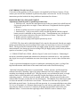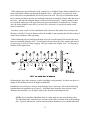
1
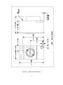
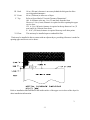
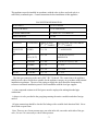
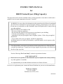
INSTRUCTION MANUAL
for
DRC55 Series Dryers (25Kg Capacity)
The dryer must not be stored or installed where it will be exposed to water and/or weather and is
suitable for use in room temperatures between 5C and 45C.
WARNING: For your safety the information in this manual must be followed to minimize
the risk of fire or explosion or to prevent property damage, personal injury or loss of life.
- Do not store or use gasoline or other flammable vapors and liquids in the vicinity of this or
any other appliance.
- WHAT TO DO IF YOU SMELL GAS
- Do not try to light any appliance.
- Do not touch any electrical switch; do not use any phone in your building.
- Clear the room, building or area of all occupants.
- Immediately call your gas supplier from a neighbor’s phone. Follow the gas supplier’s
instructions.
- If you cannot reach your gas supplier, call the fire department.
Installation and service must be performed by a qualified installer, service agency or the
gas supplier.
You, the purchaser, must post in a prominent location instructions to be followed in the
event the user smells gas. Consult your local gas supplier for procedure to be followed if
the odor of gas is present.
Post the following “For Your Safety” caution in a prominent location:
FOR YOUR SAFETY
Do not store or use gasoline or other flammable vapors or liquids in the vicinity of this or
any other appliance or machine.
It is important that you read this Manual and retain it for future reference.
For service or replacement parts, contact the Dexter Distributor in your area or the manufacturer.
The Dexter Company
2211 W. Grimes
Fairfield, Iowa 52556, USA
8514-027-005
TABLE OF CONTENTS
Page No.
Dryer Dimensions (Figure 1).............................................................................................. 3
Uncrating .......................................................................................................................... 4
Field Assembly.................................................................................................................. 4
Dryer Installation............................................................................................................... 5
Dryer Exhaust System (Figure 2)........................................................................................6, 7
Dryer Shutdown.................................................................................................................10
Operating Instructions.........................................................................................................10
Preventative Maintenance...................................................................................................14
Schematic/Wiring Diagrams.................................................................................................17, 18
WARNINGS ABOUT USE AND OPERATION
KEEP SHIELDS, GUARDS AND COVERS IN PLACE. These safety devices are
provided to protect everyone from injury.
A DRYER SHOULD BE CONNECTED TO POWER FOR THREE (3) MINUTES
before it is operated or before a program change in made. Operation or program changes which
occur during this “power up” period are subject to loss in case of power interruption. After the
initial three minutes, all programmed data is protected from power interruptions of any length and
the customer’s individual cycle is protected up to 3 seconds. This is done without batteries.
LEAVE THE ELECTRICAL POWER TO THE DRYER ON AT ALL TIMES except
when necessary for service or other similar activities. The hour meter function adds only full
hours to its reading. If the power is shut off every night, any fraction of an hour of time that is on
the machine at that time will be lost. Turning the power off every night could also have some
effect on the long term life of the memory after a number of years. Turning power off
occasionally won’t affect the unit.
From a safety aspect shutting off the gas supply at night would be better than shutting off
the electrical power.
THIS DRYER IS EQUIPPED WITH A MANUALLY RESETTABLE OVERTEMPERATURE THERMOSTAT located on the back side of the return air boot beside the
burner housing. Should the dryer cease to heat, reset the thermostat by inserting a wooden
(nonconductive) pencil or dowel through the guide bushing in the cover. Should the thermostat
continue to trip, the dryer must be inspected by a qualified service person.
CHECK THE THERMOSTAT WHEN INSTALLING DRYER to assure it is not
tripped. Impacts, such as rough handling in shipment, may trip the thermostat. It may be reset by
inserting a wooden (nonconductive) pencil or dowel through the guide bushing in the cover.
-2-
FIGURE 1 - DRYER DIMENSIONS
-3-
INSTALLATION AND OPERATING INSTRUCTIONS
Note: Before installation, check that the local distribution conditions, nature of gas and
pressure, and the adjustment of the appliance are compatible.
UNCRATING
1. Remove cardboard container and innerpack.
2. Complete the uncrating as described in the procedure listed on the instruction sheet taped to
the loading door glass.
FIELD ASSEMBLY
For secure packaging, the dryer is shipped with the tee, one part of the heat reclaimer, inside the
lower service door.
To install:
STEP 1.
Remove 4 metal screws from the bag in coin box. Go to the rear of the dryer and remove the
tape holding the top of the vertical 8 in. (200 mm) pipe.
STEP 2.
Install the tee into both the vertical pipe and the horizontal boot. Using the four pilot holes
provided, drill 4 matching 9/64 in. (3.6 mm) diameter mounting holes; 2 holes through the boot
into the tee outlet, and 2 holes through the tee inlet into the 8 in. (200 mm) vertical pipe. Install
the 4 screws provided to secure the tee to the pipe and boot.
STEP 3.
Install your exhaust system to the tee. Tape all joints with 2 in. (50 mm) duct tape.
DRYER INSTALLATION
1. CODE CONFORMITY: All commercial dryer installations must conform to the local and
national codes for the location of installation.
2. INSTALLATION CLEARANCES: This unit may be installed at the following alcove
clearance.
I. Left Side 0 in.
II. Right Side 1 in. (25 mm)*
-4-
III. Back
IV. Front
V. Top
VI. Floor
18 in. (450 mm) clearance is necessary behind the belt guard to allow
servicing and maintenance.
48 in. (1200 mm) to allow use of dryer.
Refer to figure labeled “Vertical Clearance Dimensions”.
AB. 0 clearance at the top, 1 in. (25 mm) back from the front.
However 1/4 in. (6 mm) clearance is required to allow opening the upper
service door.
CD. A 4 in. (100 mm) clearance is required at the top between 1 in. (25
mm) and 4 in. (100 mm) from front.
E. A 10" (250 mm) clearance is required from top at all other points.
This unit may be installed upon a combustible floor.
*Units may be installed in direct contact with an adjacent dryer, providing allowance is made for
opening upper and lower service doors.
Refer to installation label attached to the inside surface of the upper service door of the dryer for
other installation information.
3.
-5-
MAKE-UP AIR. Adequate make-up air (910 CFM) (26 m3/Min.) must be supplied to replace air
exhausted by dryers on all types of installations. Provide a minimum of 1.25 sq. ft.
(.12 m2) make-up air opening to the outside of each dryer. This is a net requirement of effective
area. Screens, grills or louvers which will restrict the flow of air must be considered. Consult the
supplier to determine the free area equivalent for the grill being used.
The source of make-up air should be located sufficiently away from the dryers to allow an even
air flow to the air intakes of all dryers. Multiple openings should be provided.
NOTE: The following considerations must be observed for gas dryer installations where dry
cleaners are installed. The sources of all make-up air and room ventilation air movement to all
dryers must be located away from any dry cleaners. This is necessary so that solvent vapors will
not be drawn into the dryer inlet ducts. Dry cleaner solvent vapors will decompose in contact
with open flame such as the gas flame present in clothes dryers. The decomposition products are
highly corrosive and will cause damage to the dryer(s) ducts and clothes loads.
The operation of this appliance may affect the operation of other types of gas appliances which
take their air for safe combustion from the same room. All other gas appliances should be tested
with the Dexter dryer in operation and all the windows and doors closed. If in doubt consult the
appliance manufacturer(s).
4. ELECTRICAL REQUIREMENTS: 230V~ 50Hz 1.2kW
The electrical power requirements necessary to operate the unit satisfactorily are listed on the
serial plate located on the back panel of each dryer. The electrical connection should be made to
the terminal board in the control box on the rear of the unit using a wire size adequate to handle
the amperage and voltage listed on the serial plate. It is absolutely necessary that the dryer be
grounded to a known (earth) ground.
The installation must meet the National Electrical Requirements of the country of installation.
Individual 15 A circuit breakers for each dryer are required. The installer must provide a
disconnect switch which will interrupt both lines. It may be a local or national requirement to
provide an electrical interruption switch visible and accessible from the room in which the dryer is
installed. The wiring diagram is located on the belt guard on the back of the dryer.
5. GAS REQUIREMENTS. The complete gas requirements necessary to operate the dryer
satisfactorily are listed on the serial plates located on the back panel of the dryer.
This appliance has been certified for use in the following countries: GB, IE, BE, FR, DE, NL, ES,
CH, DK and GR. This appliance is factory adjusted for G20 gas supply at either 20 or 50 mbar
supply pressure.
-6-
This appliance must be installed in accordance with the rules in force and used only in a
sufficiently ventilated space. Consult instructions before installation of this appliance.
GAS SYSTEM INFORMATION
HEAT INPUT
38.1 kW GROSS
GAS FLOW RATE
3.5 m3 PER HOUR
BURNER PRESSURE
8.7 mbar G20 / 12.2 mbar G25
INJECTOR SIZE
3.9 mm
COUNTRY
CATEGORY
ORIFICE (mm)
2ND / 3RD FAMILY
REGULATOR. SETTING mBAR
2ND / 3RD FAMILY
GB IE IT CH
ES
II 2H3+
3.9 / 2.4
8.7 / ANNULLED
FR
II
Er3+(29/37)
3.9 / 2.4
8.7 (G20),12.2 (G25) /
ANNULLED
BE
I 2E(S)B
3.9 / NA
8.7 (G20),12.2 (G25) / NA
DE
II 2EB/P
3.9 / 2.4
8.7 / 22.4
NL
II 2L3B/P(50)
3.9 / 2.4
12.2 / 22.4
DK GR
II 2H3B/P
3.9 / 2.4
8.7 / 22.4
The inlet gas connection to the unit is ISO 7-RC 3/4 thread. The connection to the appliance
shall be made with a flexible hose suitable for the appliance category in accordance with national
installation regulations. The size of the piping to supply the dryer should be determined by
reference to national installation practice and consultation with the local gas supplier.
A joint compound resistant to all fuel gases must be employed in making threaded pipe
connections.
A drip tee is to be provided in the gas piping entering the unit to catch dirt and other foreign
articles.
All pipe connections should be checked for leakage with a suitable leak detection fluid. Never
check with an open flame.
Note: There are two 9 mm pressure taps, one at the inlet side, one at the outlet side of the gas
valve, for use if it is necessary to check either pressure.
-7-
CONVERSION TO LP GAS (G30):
Conversion of this appliance to LP gas requires a kit supplied by the Dexter Company. Please
contact your local Dexter distributor to purchase the proper conversion kit. Be sure to keep the
instructions provided with the kit along with these instructions for reference.
PRESSURE REGULATOR ADJUSTMENT
Adjustments should be made by qualified personnel only.
1. With dryer off , unscrew the outlet pressure tap on the gas control valve a half turn and
slip pressure gauge tube over nipple. Ensure that screw is retightened after the regulator
is adjusted.
2. Remove regulator cap screw to expose regulator adjustment screw.
3. Start the dryer. Using a screwdriver, slowly turn the adjustment until the required
burner pressure is indicated on the pressure gauge. Turn adjustment screw clockwise to
increase and counter-clockwise to decrease gas pressure to burner. Turn dryer off.
4. Replace pressure regulator cap screw.
5. Remove pressure gauge and retighten pressure tap screw.
CAUTION: The dryer and its individual shutoff valve must be disconnected from the gas supply
piping system during any pressure testing of that system at test pressures in excess of ½ psig (35
mbar). The dryer must be isolated from the gas supply piping system by closing its individual
manual shutoff valve during any pressure testing of the gas supply piping system at test pressures
equal to or less than ½ psig (35 mbar).
6. EXHAUST INSTALLATION. (Refer to Figure 2 at the end of section 6.) Exhausting of
the dryer(s) should be planned and constructed so that no air restrictions occur. Any restriction
due to pipe size or type of installation can cause slow drying time, excessive heat, and lint in the
room.
From an operational standpoint, incorrect or inadequate exhausting can cause a cycling of the
high limit thermostat which shuts off the main burners and results in inefficient drying.
Individual exhausting of the dryers is recommended. All heat, moisture, and lint should be
exhausted outside by attaching a pipe of the proper diameter to the dryer adapter collar and
extending it out through an outside wall. This pipe must be very smooth on the inside, as rough
surfaces tend to collect lint which will eventually clog the duct and prevent the dryer from
exhausting properly. All elbows must be smooth on the inside. All joints must be made so the
exhaust end of one pipe is inside the next one downstream. The addition of an exhaust pipe tends
to reduce the amount of air the blower can exhaust. This does not affect the dryer operation if
held within practical limits. For the most efficient operation, it is recommended that no more than
20 ft. (6 m) of straight 8 in. (200 mm) diameter pipe be used with two right angle elbows. When
more than two elbows are used, 2 ft. (600 mm) of straight pipe should be removed for each
additional elbow. No more than four right angle elbows should be used to exhaust a dryer.
-8-
If the exhaust pipe passes through a wall, a metal sleeve of slightly larger diameter should be set
in the wall and the exhaust pipe passed through this sleeve. This practice is required by some
local codes and is recommended in all cases to protect the wall. This type of installation should
have a means provided to prevent rain and high winds from entering the exhaust when the dryer is
not in use. A hood with a hinged damper can be used for this purpose. Another method would
be to point the outlet end of the pipe downward to prevent entrance of wind and rain. In either
case, the outlet should be kept clear, by at least 24 in. (600 mm), of any objects which would
cause air restriction.
Provide a screen or grill over the termination of the exhaust or flue outlet such as will prevent
the entry of a ball of 16 mm in diameter while the machine is not operating but will allow entry of
a ball 6 mm in diameter while operating.
When exhausting a dryer straight up through a roof, the overall length of the duct has the same
limits as exhausting through a wall. A rain cap must be placed on top of the exhaust and must be
of such a type as to be free from clogging. The type using a cone shaped “roof” over the pipe is
suitable for this application.
Exhausting the dryer into a chimney or under a building is not permitted. In either case there is a
danger of lint buildup which can be highly combustible.
Installation of several dryers, where a main discharge duct is necessary, will need the following
considerations for installation (see Figure 2). Individual ducts from the dryers into the main
discharge duct should be at a 45 degree angle in the direction of discharge air flow.
NOTE: Never install the individual ducts at a right angle into the main discharge duct.
The individual ducts from the dryers can enter at the sides or bottom of the main discharge
duct. Figure 2 indicates the various round main duct diameters to use with the individual
-9-
dryer ducts. The main duct can be rectangular or round, provided adequate air flow is
maintained. For each individual dryer, the total exhausting (main discharge duct plus
duct outlet from the dryer) should not exceed the equivalent of 20 ft. (6 m) and two
elbows. The diameter of the main discharge duct at the last dryer must be maintained to
exhaust end.
NOTE: A small diameter duct will restrict air flow; a large diameter duct will reduce air velocity
- both contributing to lint build up. An inspection door should be provided for periodic clean-out
of the main duct.
DRYER SHUTDOWN
To render the dryer inoperative, turn off the manual gas shut-off valve and disconnect electrical
supply to the dryer.
OPERATING INSTRUCTIONS
Maximum Load Capacity: 25Kg Dry Weight
1. Deposit coins to satisfy vend price display of idle dryer. Each deposit decreases the vend price
until the display changes to show the amount of time purchased. WARM light illuminates.
2. Select drying cycle. Other cycle selections may be made now or later by pressing the
appropriate key (button).
3. Close the loading door. Press “START” and the dryer will start. The time remaining is
displayed in whole minutes (rounded up) and will count down each minute. The colon flashes on
and off indicating the timer is counting down.
4. Clothes should be removed promptly after the cycle is completed to prevent excessive
wrinkling.
Once started, the “timer” cannot be stopped. However, extra coins will be acknowledged by
adding time to the display. The dryer may be stopped by opening the loading door which
interrupts the drive motor and gas burners. Close the loading door and push “START” to restart
the dryer.
Cool-down time (owner programmable) is always part of the cycle time and is purchased by the
customer. For example, if cool-down time is 2 minutes, the last two minutes of the cycle will
have no heat.
-10-
DESCRIPTION OF CONTROLS
Credit for coins deposited, dryer time and temperature are controlled by an electronic control.
The large digital display shows vend price of an idle dryer, time purchased after coins are
deposited, temperature and program information.
The three red indicator lights show the drying temperature selected. This selection may be made
anytime.
The drying temperature will be displayed when the start switch and the switch for selected
temperature are pressed at the same time.
All programmed data is protected from power interruption of any length, and the customer’s cycle
is protected for up to 3 seconds. This is done without batteries.
The 3 temperature buttons and the start button become programming switches when the
controller is in the program mode as described below.
PROGRAMMING:
All operating parameters (vend price, temperatures, cool-down times, etc.) are adjustable. There
are also several displays of information available from the controller (money audits, hours run,
dryer temperature.)
The dryer is shipped ready for operation with the following pre-programmed data:
Temperature, HOT:
Temperature, MEDIUM:
Temperature, Warm:
Vend Price:
Time for Left Coin Slot:
Time for Right Coin Slot:
Time for Free Vend:
Cool-down Time HOT:
Cool-down Time MEDIUM:
Cool-down Time, WARM:
Temperature Scale
175 F/ 78 C
150 F/ 63 C
125 F/ 48 C
25 cents
3:20 (does not apply to single coin models)
10:00 (10 minutes for 25 cents)
10:00
2:00
2:00
2:00
F degrees
All of the above data can easily be changed by the owner. The changes are made by the 4 keys or
buttons on the front of the control panel.
-11-
CHANGING PROGRAM DATA
Put dryer in PROGRAM mode (see “Programming Instructions”). The dryer remains in the
PROGRAM mode until one of these actions occur:
•
•
•
•
The switch is actuated again.
The fifteenth step is completed, and the START switch is pushed following the fifteenth
step.
Programming is stopped for about a minute.
The loading door is closed.
Observe the displayed value in each step. If no change is required, press START to advance to
the next program step. If a change is required the values are made larger by the HOT button,
smaller by the PERM-PRESS button. The hour meter and money audit can be reset to zero if
WARM is pressed.
Note: After any reset or program change, it is necessary to advance to advance to the next step by
pressing START to enter the revision. OTHERWISE THE VALUE WILL REMAIN AS IT
WAS BEFORE THE ALTERATION.
PROGRAMMING INSTRUCTIONS:
(To switch to program mode.)
1. Unlock and open the service door.
2. Open the loading door.
3. Push the Program Button found just to the left of the warm cycle light. The Button is
accessible through a hole in the control mounting plate after the removal of the bright metal plug.
4. The control switches to PROGRAM mode. In PROGRAM mode, the membrane switch
keypad becomes a 4-switch programming tool.
5. The ACTUAL NUMERICAL VALUES desired are in as explained in the table.
IMPORTANT: Please remember to push START to actually enter (store in memory) new data.
If you merely change the display, the memory has not been changed.
-12-