1
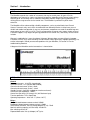
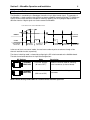
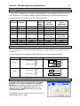
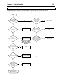
MicroMux Multiplexer USER’S GUIDE Disclaimer: The following document is provided to assist users with the installation, operation and training in the use of our products. This document and our products are intended to be used by technically qualified personnel. Contained herein is information that is proprietary to Canary Systems and may not be reproduced or copied in any form, nor disclosed to outside parties by any means whether directly or indirectly, without the written consent of Canary Systems. This document is subject to change without notice and Canary Systems assumes no responsibility for errors, omissions or misinterpretation. Furthermore Canary Systems makes no warranty as to the suitability of this information and/or products for any given application or use. Copyright2009-2010 Canary Systems, Inc. All Rights Reserved. Micromux_usersguide.doc Revision A, 02-10 Canary Systems, Inc. 75 Newport Road, Suite 211 New London, NH 03257 USA Voice: (603) 526-9800 Fax: (603) 526-9004 e-mail: [email protected] web: www.canarysystems.com Table of Contents Section 1 Introduction 1.1 Overview........................................................................................ 3 1.2 Specifications................................................................................. 3 Section 2 MultiMux Operation and Installation 2.1 Operation Details ........................................................................... 2.2 Datalogger Connection .................................................................. 2.3 Instrument Connection ................................................................... 2.4 MultiLogger Software Configuration ............................................... 2.5 CR10X Program Example.............................................................. 2.6 CR1000 Program Example ............................................................ 2.7 Using the MicroMux with the VW Comm Module............................ 2.8 Enclosure Installation ..................................................................... 2.9 Input Protection.............................................................................. 4 5 5 5 6 7 7 9 9 Section 3 Troubleshooting 3.1 Troubleshooting Flowchart ............................................................. 10 Section 1 - Introduction 3 1.1 Overview The MicroMux expands the number of instruments that may be read by most all types of 5v/12v dataloggers to 4 channels by 4 wire, or 8 channels by two wire, depending on the internal switch settings and the type of sensor being read. In addition the MicroMux provides integral lightning protection by utilizing plasma surge arrestors on the control lines. The MicroMux is provided in a panel mount enclosure. The MicroMux utilizes advanced high-reliability components such as terminal blocks from Phoenix Contact, Panasonic relays and a flash microcontroller from Microchip Devices to help insure years of reliable and trouble-free operation in most any environment (components are rated to standard long term temp range of at least -40°C to +85°C). The use of low contact resistance relays means almost universal instrument support, a high degree of lightning protection on the control lines, and virtually infinite channel isolation. Warranty is applicable for 2 years from date of shipment. Warranty does not cover failure by improper installation, misuse, or by nature including, but not limited to; flood, lightning (by improper grounding), fire, or other catastrophe. Should you encounter problems with your MicroMux, see section 3.1 for the troubleshooting flowchart. A diagram of the MicroMux terminal connections is shown below. 1.2 Specifications General Power requirements: 9-16 VDC (unregulated) Quiescent current: < 0.1 µA (Mux Not Enabled) Channel activated current (2-wire): 42mA Channel activated current (4-wire): 42mA Standby Current 1.2mA (Mux stepped past maximum channel) Control line input impedance: <10KΩ Control line input levels: 5V through 12V (16V Maximum input) Transient protection: TVS & Spark Gap Operating temperature: -40 to +85° C (-40 to +185° F) Relays Surge withstand between contacts and coil: 2500V Breakdown voltage between contacts and coil: 1,500V Initial contact resistance, max (By voltage drop 6V DC 1A): 75mΩ Nominal switching capacity (resistive load): 2A 30V DC Max switching current: 2A Expected Mechanical Life (at 180cpm): 108 Cycles Section 2 – MicroMux Operation and Installation 4 2.1 Operation Details The MicroMux is controlled by the Datalogger Controller using 2 digital control signals. The operation of the MicroMux is simple enough so that virtually any device capable of controlling 2 digital TTL/CMOS type signals can be used to control the multiplexer. Generally speaking, the timing diagram depicted below describes how the 2 digital signals are used to control the MicroMux. NOTE: TIMING VALUES SHOWN ARE MINIMUM VALUES 2 mSec 2 mSec 50 mSec ENABLE (DISABLED) 1 CLOCK CHANNEL 1 SELECTED NO CHANNEL SELECTED 15 2 CHANNEL 2 SELECTED CHANNEL 15 SELECTED 16 CHANNEL 16 SELECTED NO CHANNEL SELECTED In the case of the 4 or 8 channel modes, the maximum number of pulses to advance through all the channels would be 4 and 8, respectively. The channel switching mode is selected by configuring the DIP switch mounted on the MultiMux board. The table shown below describes the 2 possible configurations. DIP Settings Mode Description 2 8 CHANNEL RESERVED 4 Channel (Default) O N (All set to “OFF”) 4-wire instruments (4 channel board) 1 2 8 CHANNEL RESERVED 8 Channel O N 8 channel mode for switching 2-wire instruments 1 (SW1 set to “ON”) Standard 4 channel mode for switching: NOTE: Default Setting for MicroMux is 4 channel unless otherwise specified. Section 2 – MicroMux Operation and Installation 5 2.2 Datalogger Connections The MicroMux is connected to the Controller or MultiLogger Mux Terminal Board (or ML MUX TB) using the screw terminals. The common screw terminal block is located on the left side of the terminal strip The table below lists the connections for the screw terminal block: MicroMux 4 Channel MicroMux 8 Channel Description 1H 1L 2H 2L S 1H 1L Not Used Not Used S High side of CH1 Low side of CH1 High side of CH2 Low side of CH2 Cable Shield 10-Pin Bendix (16/32 board) A B C D K 12V G EN CLK 12V GND EN CLK Power Ground Enable Clock F G H J Mux Cable (5 pair) (4/8 board) Mux Cable (6 pair) (48Ch board) White White’s Black Red Red’s Black Shield Wires from White & Red Pair plus Overall Yellow Yellow’s Black Green Green’s Black Brown Brown’s Black Red Red’s Black Shield Wires from Brown & Red Pair plus Overall Yellow Yellow’s Black Green Green’s Black 2.3 Instrument Connection The way instruments are connected to the MicroMux will vary slightly depending on the Mode selection (section 2.1). The following table illustrates typical connection techniques for each of the operating modes. Mode 4 Channel (4-wire) Description Example H1 H1 INSTRUMENT #1 L1 L1 H2 H2 L2 L2 H1 H1 L1 L1 H2 H2 L2 L2 TEMPERATURE #1 8 Channel (2-wire) INSTRUMENT #1 INSTRUMENT #2 2.4 MultiLogger Software Configuration To configure MultiLogger to use the MicroMux select CAN MicroMux as your multiplexer Model on the Configure | Multiplexers form. Before the individual channels may be edited you must select a Gage Type. Select either 4 Channels (default), 8 Channels to match the DIP switch settings of the MicroMux. If the VWDSP Interface is being used, be sure to select the VWDSP Gage Type, as shown. Section 2 – MicroMux Operation and Installation 6 2.5 CR10X Program Example The following example illustrates how to write custom programs for the CR10X to read instruments connected to the MicroMux. The example assumes a 4 Channel Mode MultiMux reading 4 vibrating wire gages and their respective thermistors. The program example illustrates how measurements of instruments connected to the MicroMux are read, it does not include instructions that would store the measurements for later retrieval. Consult the CR10X Operators Manual for more information on storing measurements. 1: Set Port(s) (P20) ;Configure the control ports of the CR10/CR10X, C1=Enable, C8=Clock 1: 7999 C8..C5 = output/nc/nc/nc 2: 9994 C4..C1 = nc/nc/nc/10ms 2: Do (P86) ;Enable the MultiMux 1: 41 Set Port 1 High 3: 1: 2: 3: 4: Excitation with Delay (P22) ;50ms delay after enabling the MicroMux 1 Ex Channel 0 Delay W/Ex (units = 0.01 sec) 5 Delay After Ex (units = 0.01 sec) 0 mV Excitation 4: Beginning of Loop (P87) 1: 0 Delay 2: 4 Loop Count ;Total number of instruments 5: Do (P86) ;Advance the channel 1: 78 Pulse Port 8 6: 1: 2: 3: 4: 5: 6: 7: 8: 9: 10: Vibrating Wire (SE) (P28) ;Read the Vibrating Wire Gage 1 Reps 1 SE Channel 1 Excite all reps w/Exchan 1 20 Starting Freq. (units = 100 Hz) 35 End Freq. (units = 100 Hz) 250 No. of Cycles 0 Rep Delay (units = 0.01 sec) 1 -- Loc [ VWGage_1 ] 1000 Mult 0 Offset 7: 1: 2: 3: 4: 5: 6: 7: 8: 9: Excite-Delay (SE) (P4) ;Read the Thermistor 1 Reps 5 2500 mV Slow Range 2 SE Channel 1 Excite all reps w/Exchan 1 5 Delay (units 0.01 sec) 2500 mV Excitation 17 -- Loc [ VWTemp_1 ] .001 Mult 0 Offset 8: 1: 2: 3: 4: 5: 6: 7: 8: 9: Polynomial (P55) ;Convert thermistor voltage to °C 1 Reps 17 -- X Loc [ VWTemp_1 ] 17 -- F(X) Loc [ VWTemp_1 ] -104.78 C0 378.11 C1 -611.59 C2 544.27 C3 -240.91 C4 43.089 C5 9: End (P95) ;End of measurement loop Section 2 – MicroMux Operation and Installation 7 2.6 CR1000 Program Example 'Enable our multiplexer PortSet (1,1) 'Wait 100mSec for multiplexer to power up Delay(0,100,MSEC) 'Cycle through 4 channels For Channel = 1 TO 4 'Set Clock port high to advance mux channel PortSet(8,1) 'Wait 10mSec for 50% duty cycle Delay(0,10,MSEC) 'Set Clock port low PortSet(8,0) 'Wait 10mSec for channel to settle Delay(0,10,MSEC) 'Read our vibrating wire gage VibratingWire(MuxChannel(),1,mV7_5,2,VX1,600,3600,500,-1,20000,500,0,1,0) 'Read our YSI44005 type thermistor BrHalf(ScratchLoc(1),1,mV2500,2,VX1,1,2500,0,1000,250,2.5,0.0) ScratchLoc(2) = ScratchLoc(1) / 5000 ScratchLoc(3) = (2.5 - (ScratchLoc(2)*1000) - ScratchLoc(1))/ScratchLoc(2) MuxChannelTemp() = 1/(.0014051 + (.0002369*Log(ScratchLoc(3))) + (.0000001019*(Log(ScratchLoc(3))^3))) - 273.2 'End of measurement loop Next 'Disable our multiplexer PortSet (1,0) 2.7 Using the MicroMux with the VW Comm Module The VW Comm has built in instructions to directly control the MicroMux, MultiMux, or MiniMux. There are specific gage types in Multilogger Software to configure the VW Comm to be connected to 4 or 8 sensors through the MIcroMux. The VW Comm can be used with a radio, and MicroMux as a remote node for 4 or 8 instruments. 'Read vibrating wire gage using a VW Comm at address 0 using Mux channel MicroMux'on a Digi radio at address 0129. Radio network must match base station ScratchLoc(1) = -99999 ScratchLoc(2) = -99999 ScratchLoc(3) = -99999 ScratchLoc(4) = -99999 ScratchLoc(5) = -99999 ScratchLoc(6) = -99999 ScratchLoc(7) = -99999 ScratchLoc(8) = -99999 ScratchLoc(9) = -99999 ScratchLoc(10) = -99999 ScratchLoc(11) = -99999 ScratchLoc(12) = -99999 'Open our port SerialOpen (Com1,9600,0,100,255) 'open COM1 - C1&C2 Delay(0,1000,mSec) 'must wait 1 second before AT Command mode 'Transmit ===, Receive OK (wait up to 10 seconds) SerialOut (Com1,"===","OK",2,5000) Delay(0,1000,mSec) 'must wait 1 second after AT Command mode Section 2 – MicroMux Operation and Installation 'Transmit ATDTnn (where nn = radio address), Receive OK (up to 10 seconds) SerialOut (Com1,"ATDT0129"+Chr(13),"OK",1,1000) Delay(0,1000,mSec) 'Transmit ATCN, Receive OK (wait up to 10 seconds) SerialOut (Com1,"ATCN"+Chr(13),"OK",1,1000) 'Wake up the VW Comm - Try for 5 seconds ScratchLoc(1) = SerialOut (Com1,"0!","0",50,100) 'Check for valid response if ScratchLoc(1) <> 0 then 'Send Set Digital Outputs command (Switch to Gage 1) SerialOut (Com1,"0MM00!","00045",5,50) 'Send Set Up VW Start Freq, End Freq, command SerialOut (Com1,"0M110400350002550500!","00045",5,50) ScratchLoc(4)= FormatFloat(Channel, "%2g") 'Send Set Digital Outputs command (Switch to Gage 1) SerialOut (Com1,"0MM0"+ScratchLoc(4)+"!","00045",5,50) 'Send Take Reading command SerialOut (Com1,"0M!","00045",5,50) SerialFlush(com1) Delay(0,1500,mSec) 'Send Get Readings command SerialOut (Com1,"0D0!","0",5,50) 'Receive response SerialIn(sInBuf,Com1,100,CHR(13),75) 'Get length of response buffer ScratchLoc(3) = Len(sInBuf) if Len(sInBuf) >= 9 then 'Split out response values Splitstr(ScratchLoc(4),sInBuf,"",12,0) 'Convert to reading - may be in Digits, Freq, or Period mlReading=ScratchLoc(4) Else 'No valid response mlReading = -99999 EndIf 'Send Set Digital Outputs command (Switch back to Gage 1) SerialOut (Com1,"0M6000!","00045",5,250) Else 'No valid response mlReading = -99998 EndIf 'Close our serial port SerialClose(Com1) 8 Section 2 – MultiMux Operation and Installation 9 2.8 Enclosure Installation The MicroMux can be attached to any surface with 4 mounting 6-32 screws. The placement of the mounting holes is depicted in the illustration below. 6 inches Made in the U.S.A. www.canarysystems.com MicroMux4 2 inches 6 inches = 15.2cm 2 inches = 5.1cm SHIELD S VW Gage 4H2 4L2 4L1 CHANNEL 4 4H1 VW Gage 3L2 3H2 3L1 CHANNEL 3 3H1 VW Gage 2L2 2H2 CHANNEL 2 2H1 1L2 1L1 1H2 CLK 1H1 CHANNEL 1 2L1 VW Gage G EN S 12V L2 H2 L1 H1 COMMON VW Gage CURRENT LIMIT: 2A 30VDC MAX Note: The Micromux can be installed upside down, vertically, or horizontally. 2.9 Input Protection The MicroMux is equipped with lightning protection components on the control signals. As a result, care must be exercised in the installation to maximize their effectiveness. Specifically, an effective earth ground must be attached to the MicroMux shield (S) for proper protection. Most Vibrating wire instruments also have lightning protection components. The Enable and Clock inputs can be connected to 12 volts directly without damaging the MicroMux. The connections to the datalogger should be disconnected and insulated from contacting other electrical connections. The 12V tolerant inputs allow the MicroMux to be field tested without the need for a datalogger connection. The enable can be wired to the 12V input while the clock input can be touched to 12V. This action will cause the MicroMux to step channels for each touch to 12 volts. Section 3 – Troubleshooting 10 3.1 Troubleshooting Flowchart If you cannot obtain readings using the MicroMux or the readings are unstable then see the troubleshooting flowchart below for help in determining the nature of the problem. Start Does the MicroMux advance through the channels? No Yes Are the switched leads connected? No Connect the leads Are the Enable and Clock lines connected to the control ports? No Adjust the wiring for the type of sensor used Note: See the MultiSensor Interface User's Guide or MultiLogger Software User's Guide for wiring diagrams. No Adjust the software settings Yes Remove the noise source or move the MicroMux Do the software settings for the Enable and Clock lines match the connections? Yes Is there a source of electrical noise nearby? No Do the circuit boards show water or other contamination? No Call Canary Systems for further assistance Attach 12V and G No Attach Enable & Clock lines No Match software and digital I/O connections Yes Yes Do the software settings match the sensor type and wiring? No Yes Yes Is the wiring correct for the sensor leads? Is 12V and G connected to the MicroMux? Yes Clean the circuit boards Yes