1
elektronik mainz
OS-9 V2.4 on EUROCOM-17
Installation Guide
Software Manual
Revision 1 A
Revision History
Rev.
1A
OS-9 V2.4 on EUROCOM-17
Changes
Date
First Edition
valid for Software Revision 1.A
28.09.93, D.W.
DISCLAIMER!
The information in this document has been carefully checked and is believed to be entirely reliable. However, no responsibility
is assumed for inaccuracies. ELTEC reserves the right to make changes to any products to improve reliability, function or
design. ELTEC does not assume any liability arising out of the application or use of any product or circuit described in this
manual; neither does it convey any license under its patent rights nor the rights of others. ELTEC products are not authorized
for use as components in life support devices or systems intended for surgical implant into the body or intended to support or
sustain life. Buyer agrees to notify ELTEC of any such intended end use whereupon ELTEC shall determine availability and
suitability of its product or products for the use intended.
ELTEC points out that there is no legal obligation to document internal relationships between any functional modules, realized
in either hardware or software, of a delivered entity.
This document contains copyrighted information. All rights including those of translation, reprint, broadcasting,
photomechanical or similar reproduction and storage or processing in computer systems, in whole or in part, are reserved.
EUROCOM is a trademark of ELTEC Elektronik AG. Other brands and their products are trademarks of their respective
holders and should be noted as such.
© 1993 ELTEC Elektronik AG, Mainz
ELTEC Elektronik AG
Galileo-Galilei-Str. 11
D-55129 Mainz
Telephone
Telefax
Postfach 42 13 63
D-55071 Mainz
+49 (61 31) 9 18-0
+49 (61 31) 9 18-1 99
OS-9 V2.4 on EUROCOM-17
Table of Contents
Table of Contents
Page
Table of Contents . . . . . . . . . . . . . . . . . . . . . . . . . . . . . . . . . . . . . . . . . . . . . . . . . . . . . . . . . . . . . . . . I
List of Tables . . . . . . . . . . . . . . . . . . . . . . . . . . . . . . . . . . . . . . . . . . . . . . . . . . . . . . . . . . . . . . . . . . III
Scope of Delivery . . . . . . . . . . . . . . . . . . . . . . . . . . . . . . . . . . . . . . . . . . . . . . . . . . . . . . . . . . . . . . . .V
Options and Related Products. . . . . . . . . . . . . . . . . . . . . . . . . . . . . . . . . . . . . . . . . . . . . . . . . . . . . . VI
Conventions . . . . . . . . . . . . . . . . . . . . . . . . . . . . . . . . . . . . . . . . . . . . . . . . . . . . . . . . . . . . . . . . . . VII
How to Use this Manual . . . . . . . . . . . . . . . . . . . . . . . . . . . . . . . . . . . . . . . . . . . . . . . . . . . . . . . . .VIII
1 Getting Started . . . . . . . . . . . . . . . . . . . . . . . . . . . . . . . . . . . . . . . . . . . . . . . . . . . . . . . . . . . . . . . . . 1
1.1
Pre-Installed System . . . . . . . . . . . . . . . . . . . . . . . . . . . . . . . . . . . . . . . . . . . . . . . . . . . . . . . . . 1
1.2
No Pre-Installed System . . . . . . . . . . . . . . . . . . . . . . . . . . . . . . . . . . . . . . . . . . . . . . . . . . . . . . 1
2 Installing OS-9 V2.4.5 . . . . . . . . . . . . . . . . . . . . . . . . . . . . . . . . . . . . . . . . . . . . . . . . . . . . . . . . . . . 3
2.1
Booting from Floppy Disk. . . . . . . . . . . . . . . . . . . . . . . . . . . . . . . . . . . . . . . . . . . . . . . . . . . . . 3
2.2
Installing OS-9 V2.4.5 on an Empty Harddisk . . . . . . . . . . . . . . . . . . . . . . . . . . . . . . . . . . . . . 5
2.3
Updating OS-9 V2.X to V2.4.5 . . . . . . . . . . . . . . . . . . . . . . . . . . . . . . . . . . . . . . . . . . . . . . . . . 6
2.4
68040 Cache Configuration. . . . . . . . . . . . . . . . . . . . . . . . . . . . . . . . . . . . . . . . . . . . . . . . . . . . 7
2.4.1
Standard OS-9 Configuration including SSM . . . . . . . . . . . . . . . . . . . . . . . . . . . . . . 7
2.4.2
OS-9 Configuration without SSM. . . . . . . . . . . . . . . . . . . . . . . . . . . . . . . . . . . . . . . . 8
2.4.3
Cache Configuration with CacheList . . . . . . . . . . . . . . . . . . . . . . . . . . . . . . . . . . . . . 8
2.4.4
Notes and Restrictions . . . . . . . . . . . . . . . . . . . . . . . . . . . . . . . . . . . . . . . . . . . . . . . . 9
2.5
Floating Point Support. . . . . . . . . . . . . . . . . . . . . . . . . . . . . . . . . . . . . . . . . . . . . . . . . . . . . . . 10
2.6
Memory Configuration with MemList . . . . . . . . . . . . . . . . . . . . . . . . . . . . . . . . . . . . . . . . . . 11
3 Drivers and Descriptors . . . . . . . . . . . . . . . . . . . . . . . . . . . . . . . . . . . . . . . . . . . . . . . . . . . . . . . . 13
3.1
Clock Module . . . . . . . . . . . . . . . . . . . . . . . . . . . . . . . . . . . . . . . . . . . . . . . . . . . . . . . . . . . . . 13
3.2
RBF Drivers. . . . . . . . . . . . . . . . . . . . . . . . . . . . . . . . . . . . . . . . . . . . . . . . . . . . . . . . . . . . . . . 14
Software Manual
I
Table of Contents (Continued)
OS-9 V2.4 on EUROCOM-17
Page
3.3
RBF Descriptors . . . . . . . . . . . . . . . . . . . . . . . . . . . . . . . . . . . . . . . . . . . . . . . . . . . . . . . . . . . 15
3.3.1
Descriptors for Harddisk with embedded SCSI . . . . . . . . . . . . . . . . . . . . . . . . . . . . 15
3.3.2
Descriptors for TEAC FC-1 Controller. . . . . . . . . . . . . . . . . . . . . . . . . . . . . . . . . . . 16
3.3.3
Descriptors for SCFL Controller. . . . . . . . . . . . . . . . . . . . . . . . . . . . . . . . . . . . . . . . 16
3.4
SCF Drivers and Descriptors . . . . . . . . . . . . . . . . . . . . . . . . . . . . . . . . . . . . . . . . . . . . . . . . . . 17
3.5
SBF Drivers and Descriptors . . . . . . . . . . . . . . . . . . . . . . . . . . . . . . . . . . . . . . . . . . . . . . . . . . 19
3.6
PCF - The PC File Manager . . . . . . . . . . . . . . . . . . . . . . . . . . . . . . . . . . . . . . . . . . . . . . . . . . 19
4 Installing new RBF Devices . . . . . . . . . . . . . . . . . . . . . . . . . . . . . . . . . . . . . . . . . . . . . . . . . . . . . . 21
4.1
Installing New Harddisks with Embedded SCSI Controllers . . . . . . . . . . . . . . . . . . . . . . . . . 21
4.1.1
4.2
Changing the Sector Size on SCSI Drives . . . . . . . . . . . . . . . . . . . . . . . . . . . . . . . . 21
Fixed Device Parameters . . . . . . . . . . . . . . . . . . . . . . . . . . . . . . . . . . . . . . . . . . . . . . . . . . . . . 22
5 Features and Enhancements . . . . . . . . . . . . . . . . . . . . . . . . . . . . . . . . . . . . . . . . . . . . . . . . . . . . . 23
5.1
Sysgo . . . . . . . . . . . . . . . . . . . . . . . . . . . . . . . . . . . . . . . . . . . . . . . . . . . . . . . . . . . . . . . . . . . . 23
5.2
Init . . . . . . . . . . . . . . . . . . . . . . . . . . . . . . . . . . . . . . . . . . . . . . . . . . . . . . . . . . . . . . . . . . . . . . 23
6 Additional Utilities . . . . . . . . . . . . . . . . . . . . . . . . . . . . . . . . . . . . . . . . . . . . . . . . . . . . . . . . . . . . . 25
6.1
Dmode Utility . . . . . . . . . . . . . . . . . . . . . . . . . . . . . . . . . . . . . . . . . . . . . . . . . . . . . . . . . . . . . 25
6.2
Back Utility . . . . . . . . . . . . . . . . . . . . . . . . . . . . . . . . . . . . . . . . . . . . . . . . . . . . . . . . . . . . . . . 26
7 Additional Libraries . . . . . . . . . . . . . . . . . . . . . . . . . . . . . . . . . . . . . . . . . . . . . . . . . . . . . . . . . . . 31
7.1
The F$System System Call . . . . . . . . . . . . . . . . . . . . . . . . . . . . . . . . . . . . . . . . . . . . . . . . . . . 31
7.2
The Assembler Library LIBELTEC . . . . . . . . . . . . . . . . . . . . . . . . . . . . . . . . . . . . . . . . . . . . 32
7.3
The C Library CLIBELTEC . . . . . . . . . . . . . . . . . . . . . . . . . . . . . . . . . . . . . . . . . . . . . . . . . . 45
Appendix A: Control Sequence Codes . . . . . . . . . . . . . . . . . . . . . . . . . . . . . . . . . . . . . . . . . . . . . . . . 53
Technical Action Request Form Sheet
Reader Comments Form Sheet
II
Software Manual
OS-9 V2.4 on EUROCOM-17
List of Tables
List of Tables
Page
Table 1:
Table 2:
Table 3:
Available SCF Descriptors and Appropriate Drivers . . . . . . . . . . . . . . . . . . . . . . . . . . . . . 18
Available SBF Descriptors and Appropriate Drivers . . . . . . . . . . . . . . . . . . . . . . . . . . . . . 19
Used SCSI IDs on EUROCOM-17 . . . . . . . . . . . . . . . . . . . . . . . . . . . . . . . . . . . . . . . . . . . 22
Software Manual
III
OS-9 V2.4 on EUROCOM-17
IV
Software Manual
OS-9 V2.4 on EUROCOM-17
Scope of Delivery
Scope of Delivery
Description:
Order No.:
OS-9 V2.4.5
Professional OS-9 V2.4.5 for EUROCOM-17
Industrial MGR 1.3
i
W-O917-A105
The last letter of the order numbers refers to the software revision and is
subject to changes. Please contact ELTEC for information about valid
order numbers.
Example:
W-O916-B105
Revision number, subject to change!
Software Manual
V
Options / Related Products
OS-9 V2.4 on EUROCOM-17
Options
Description:
Order No.:
None
Related Products
Description:
Order No.:
Documentation:
Software Manual OS-9 V2.4 on EUROCOM-17
Hardware Manual EUROCOM-17
Software Manual RMon
H-O917-A109
V-E17.-A991
W-FIRM-A209
Hardware:
EUROCOM-17, 33 MHz, 32 MB
EUROCOM-17, 33 MHz, 8 MB
EUROCOM-17, 25 MHz, 8 MB
EUROCOM-17, 25 MHz, 2 MB
V-E17.-A139
V-E17.-A113
V-E17.-A103
V-E17.-A100
Software:
None
Data Sheets:
None
i
The last letter of the order numbers refers to the hardware revision and is
subject to changes. Please contact ELTEC for information about valid
order numbers.
Example:
V-E16.-B105
Revision number, subject to change!
VI
Software Manual
OS-9 V2.4 on EUROCOM-17
Conventions
Conventions
If not otherwise specified, addresses are written in hexadecimal notation
and identified by a leading dollar sign ("$").
Signal names preceded by a slash ("/"), indicate that this signal is either
active low or that this signal becomes active with the trailing edge.
b
B
K
M
MHz
bit
byte
kilo, means the factor 400 in hex (1024 decimal)
mega, the multiplication with 100 000 in hex (1 048576 decimal)
1 000 000 Hertz
Software-specific abbreviations:
<BS>
Back Space ($8)
<CAN> Control-X ($19)
<Ctrl>
Control
<CR>
Carriage Return ($D)
<ESC> Escape Character ($2B)
<LF>
Line Feed ($A)
<SP>
Space ($20)
NMI
Non-maskable Interrupt
Software Manual
VII
How to Use this Manual
OS-9 V2.4 on EUROCOM-17
How to Use this Manual
Document Conventions
Font Types:
Font
Use
Helvetica, 8 Pt
Tables and drawings
Helvetica, 10 Pt
Signal names
Times, italic
Notes
Courier, bold
Program code, function names, commands,
file names, module names
Times, bold
Emphasized text
Other conventions:
i
!
Indicates information that requires close attention.
Indicates critical information that is essential to read.
Indicates information that is imperative to read. Skipping this
material, possibly causes damage to the system.
VIII
Software Manual
OS-9 V2.4 on EUROCOM-17
1 Getting Started
1 Getting Started
This manual contains informations about the implementation dependent
part of OS-9/68K ELTEC systems.
We recommend, that you are familiar with the following documentations:
•EUROCOM-17 Hardware Manual
•RMon Manual
•OS-9/68K Users Manual
•Using UMACS
1.1 Pre-Installed System
If you have ordered a complete system, the operating system will already
be installed completely on the harddisk, when shipped off. You do not
need the floppy disks delivered with the system and you are also not
concerned with the whole installing procedure (hardware configuration,
formatting, copying, ...) as described in this manual (... until the next OS-9
update arrives).
Only in case of a total crash of the system these disks are used to
reconfigure the system as described - so keep these disks in a save place!
1.2 No Pre-Installed System
If you want to use a serial line terminal, configure it as follows:
9600 baud,
1 start bit,
8 data bits,
1 stop bit,
no parity.
Then connect the RJ11 socket and the terminal I/O socket. Set hex switch
S2 on front panel to 3 for serial I/O with RMon. If you are not using an
ELTEC cable, refer to the hardware manual for correct connection of
signals.
Software Manual
1
1 Getting Started
OS-9 V2.4 on EUROCOM-17
If you want to use a VGA monitor and MF-2 keyboard, set hex switch S2
to '0'.
Connect the floppy drive(s) and harddisk(s) according to the description in
the hardware manual and jumper them as mentioned in Section 4.2 ‘Fixed
Device Parameters’of this manual.
Now switch on the terminal and the EUROCOM-17. The LED display
now indicates 'F', and you should get the power-on message of the RMon
monitor from the terminal.
The monitor program on EUROCOM-17 has a SCSI command (check
SCSI bus). This command can be used to check connected devices on the
SCSI bus. It checks SCSI IDs 0 till 6 and on each ID logical unit number
(LUN) 0 till 3. For ever ready device a '+' is issued.
At this point boot OS-9/68K (see Section 2.1 ‘Booting from Floppy
Disk’).
2
Software Manual
OS-9 V2.4 on EUROCOM-17
2 Installing OS-9 V2.4.5
2 Installing OS-9 V2.4.5
This chapter explains the installation of the new OS-9 release on a
harddisk.
2.1 Booting from Floppy Disk
After power-up, the EUROCOM-17 prompts with its monitor program.
All commands described in the RMon manual are ready to be used. Insert
disk labeled ‘OS9 Bootdisk’into drive 0 if you wish to boot from floppy.
i
If you ordered a system with harddisk, the whole operating system and the
boot file are installed on the harddisk by ELTEC. In this case skip the
steps 1 to 4 and boot directly.
In the following items enclosed in " " are monitor prompts. Your response
are enclosed in ' '.
i
i
The description of the set command refers to RMon Version 2.0.
The answers to the prompts given below correspond to the OS-9 as
delivered by ELTEC. Selecting other SCSI IDs or LUNs means that you
first have to configure your own corresponding OS-9 system.
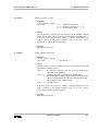
"[***]>"
1. Type 'set<CR>' to enter the configuration set.
"Select item: "
Type 'e' for boot configuration.
2. Type 'b' to change boot device.
"Boot device: Harddisk"
Press '<SP>' to select floppy as boot device.
Press '<CR>' to accept.
Software Manual
3
2 Installing OS-9 V2.4.5
OS-9 V2.4 on EUROCOM-17
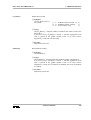
Type 'c' to change boot controller.
"Controller: TEAC"
Press '<SP>' to select SCFL as boot device.
Press '<CR>' to accept.
3. Type 'x' to exit boot menu.
4. Type 'x' to exit setup menu.
"Save parameters (y/n)?"
Type 'y' to save the selected parameters.
"[***]>"
5. Type 'boot<CR>' to boot OS-9/68K.
6. The boot device is selected and the operating system comes up.
If you have booted from floppy disk and want to attach the harddisk, you
have to load the harddisk descriptor first. (It can be found in directory
CMDS/BOOTOBJS). The name of the harddisk descriptor depends on the
hardware, but is normally h0.embscsi (harddisk with SCSI ID 6). See
Section 3.3 ‘RBF Descriptors’.
$ chd /d0/cmds/bootobjs
$ load -d h0.embscsi
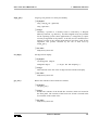
If there is no pre-installed operating system on the harddisk, it has to be
formatted. In case of a harddisk with embedded SCSI, the format has to be
performed in two steps:
1. Clear Format Inhibit bit in descriptor with dmode utility.
$ dmode /h0 format=on
2. Logical format of the disk with OS-9 format command (for more
information, refer to the OS-9 manual).
$ format /h0
and answer all questions with 'y'.
4
Software Manual
OS-9 V2.4 on EUROCOM-17
2 Installing OS-9 V2.4.5
2.2 Installing OS-9 V2.4.5 on an Empty Harddisk
It is recommended to install the operating system on a fresh formatted
harddisk. Boot the system from floppy, load the appropriate harddisk
descriptor and format the harddisk (see Section 2.1 ‘Booting from Floppy
Disk’).
1. Load the back utility from your boot disk and change the current
directory to harddisk.
$ load back
$ chd /h0
2. Copy the all floppy disks in ascending order to the harddisk using the
back utility.
$ back /d0 /h0 -r
Use the '-r' (rewrite) option because disks contain some files twice.
i
In some cases the OS-9 was delivered with an addendum disk with new or
bugfixed modules. See the file ReadMe.Addendum on this disk for further
details.
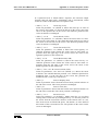
3. Generate a new boot file on the harddisk with os9gen . Examine the
sample bootlist file in CMDS/BOOTOBJS. Add the drivers and
descriptors needed for the system. For the information which drivers
and descriptors are needed, refer to Chapter 3 ‘Drivers and
Descriptors’.
$ chd /h0/cmds/bootobjs
$ dmode /h0 format=on
$ os9gen /h0 -z=bootlist -eb=200
i
The harddisk descriptor may have the Format Inhibit bit set. This results
in error 000:255 (E$Format) when trying to write to sector 0 (like
os9gen ). Use the dmode utility to clear this bit ( dmode /h0 format=on ).
4. Reset the system and reboot the operating system.
i
The memory size is set to 2 MB per default, so you have to configure the
memory list in the init module (see Section 2.6 ‘Memory Configuration
with MemList’).
Software Manual
5
2 Installing OS-9 V2.4.5
OS-9 V2.4 on EUROCOM-17
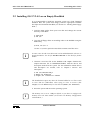
2.3 Updating OS-9 V2.X to V2.4.5
Installing the software on a harddisk already containing an OS-9 (older
version or version for a different CPU) may cause trouble if modules are
mixed between different releases. The following procedure is a save way
to avoid this:
0. Make a complete backup of the harddisk.
1. Generate a bootable floppy with the old version of the operating
system.
2. Load the back utility into memory and change the current directory to
harddisk.
$ load back
$ chd /h0
Rename the directories CMDS, C, LIB, SYS, DEFS, IO, SYSSRC,
README and startup file (e.g., CMDS.OLD, C.OLD, etc.).
$ rename CMDS CMD.OLD
$ rename C C.OLD
.
.
.
$ rename startup startup.old
3. Copy the all floppy disks in ascending order to the harddisk by using
the back utility.
$ back /d0 /h0 -r
Use the '-r' (rewrite) option to be sure to overwrite the old modules.
i
6
In some cases the OS-9 was delivered an addendum disk with new or
bugfixed modules. See the file ReadMe.Addendum on this disk for further
details.
Software Manual
OS-9 V2.4 on EUROCOM-17
2 Installing OS-9 V2.4.5
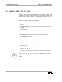
4. Generate a new boot file on the harddisk with os9gen . Examine the
sample bootlist file in CMDS/BOOTOBJS and add the necessary
drivers and descriptors. For the information which drivers and
descriptors are needed, refer to Chapter 3 ‘Drivers and Descriptors’.
$ chd /h0/cmds/bootobjs
$ dmode /h0 format=on
$ os9gen /h0 -z=bootlist -eb=200
i
The harddisk descriptor may have the Format Inhibit bit set. This results
in error 000:255 (E$Format) when trying to write to sector 0 (like
os9gen ). Use the dmode utility to clear this bit ( dmode /h0 format=on ).
5. Reset the system and reboot the operating system.
i
The memory size is set to 2 MB per default, so you have to configure the
memory list in the init module (see Section 2.6 ‘Memory Configuration
with MemList’).
6. Now copy everything from the renamed directories that is not already
contained in the new directory. Typically things which do not belong
to the OS-9 operating system. Check carefully if this software is still
operateable before usage.
2.4 68040 Cache Configuration
2.4.1
Standard OS-9
Configuration
including SSM
The usage of the ssm040 module also implies the usage of the original
Microware syscache040 module, which is located in the file
syscache040 .
In this case the cache operating mode is selected by the ssm040 code:
ssm040.cbsup
ssm040
- cache enabled in supervisor state, copy back mode
- cache enabled in supervisor state, write through mode
If you want to change cache modes and areas in user state, the cache list in
module init.a has to be changed (see Section 2.4.3 ‘Cache Configuration
with CacheList’for details).
Software Manual
7
2 Installing OS-9 V2.4.5
2.4.2
OS-9
Configuration
without SSM
OS-9 V2.4 on EUROCOM-17
ELTEC supplies two modified syscache040 modules, which configure
the address space of the EUROCOM-17 as follows:
syscache040.cb
$0000.0000 - $01FF.FFFF: both caches enabled, copy back mode
$0200.0000 - $FDFF.FFFF: both caches enabled, write through mode
$FE00.0000 - $FFFF.FFFF: both caches disabled, all serialized
syscache040.wt
$0000.0000 - $01FF.FFFF: both caches enabled, write through mode
$0200.0000 - $FDFF.FFFF: both caches enabled, write through mode
$FE00.0000 - $FFFF.FFFF: both caches disabled, all serialized
Using the caches in copy back mode will result in best CPU performance.
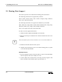
2.4.3
Cache
Configuration
with CacheList
The configuration for the on-chip cache is stored in a data structure called
CacheList in the INIT module. The cache size is set to 2 MB per default
with the UsrMemEnd label in DEFS/ systype.d . If a EUROCOM-17 with a
different memory size is used, modify UsrMemEnd or choose one of the
uncommented samples in DEFS/ systype.d for optimal performance. Set
the 2 MB UsrMemEnd to comment and remove the comment for your
configuration. Init.a contains the following CacheList:
CacheList
* Select one of predefined UsrMemEnd labels in systype.d
(default is 2 MB)
*
StartAddr,EndAddr+1,Mode
CacheType $00020000,UsrMemEnd,CopyBack
CacheType UsrMemEnd,$FFFFFFFF,CISer
Define start point, end point(+1) of cache area and cache mode. Valid
modes are CopyBack, WrtThru, CISer and CINotSer. It is possible to
define different cache modes for parts of the system memory. If you want
to change the cache list, edit the file init.a in directory SYSSRC. After
modification of init.a reassemble the file with the following command:
$ make init
Now a new INIT
CMDS/BOOTOBJS.
module is built and stored as
init
in
Examine the bootlist file in CMDS/BOOTOBJS, generate a new
bootfile on the harddisk with os9gen and reboot the system.
8
Software Manual
OS-9 V2.4 on EUROCOM-17
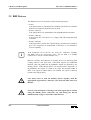
2.4.4
Notes and
Restrictions
2 Installing OS-9 V2.4.5
The DDIO bit in module init is set by default. This tells the kernel not to
disable the data cache when in I/O.
Disabling data cache is required for systems with drivers which use DMA
and don't perform any explicit data cache flushing. If your system does not
use DMA drivers, or the drivers care for the cache, the DDIO bit should be
set.
The DDIO bit has to be modify by the label NoDataDis in systype.d . If
you want to unset the DDIO bit, set to comment the label NoDataDis in
DEFS/systype.d and remake the init module.
The syscache040/ssm040 modules are only for 68040 and 68LC040
systems. For 68EC040 configuration, see Section 2.4.2 ‘OS-9
Configuration without SSM’.
If you want to set breakpoints in the system level debugger, the caches
have to operate in write through mode!
Software Manual
9
2 Installing OS-9 V2.4.5
OS-9 V2.4 on EUROCOM-17
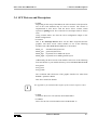
2.5 Floating Point Support
This release provides soft- and hardware floating point instructions.
The following instructions are supported by software:
facos , fasin , fatan , fetox , fint , fintrz , flog10 , flogn , fmovecr ,
fsin , fcos , ftan and ftentox .
The following instructions are supported in hardware by the 68040:
fabs , fadd , fbcc , fcmp , fdbcc , fdiff , fmove , fmovem , fmul , fneg , fnop ,
frestore , fsave , fscc , fsqrt , fsub , ftrapcc and ftst .
There is no support for fcosh , fsinh and ftanh.
In order to use the supported functions:
1. Add the modules fpu040 and math881 to the bootlist.
2. Make sure that fpu is included in the extension module list in the init
module.
i
The init module of this release includes a correct extension module list.
3. Remake the bootfile and reboot the system.
4. Compile code with option '-k=2f' to use inline floating point, or option
'-x' use the math trap handler.
RESTRICTIONS:
1. The fpu emulation requires the D50 mask or better of the MC68040,
f-line exceptions will occur if mask is too low.
2. At least edition 109 of the kernel is necessary for FPU support. This
release includes kernel edition equal or greater than 135.
10
Software Manual
OS-9 V2.4 on EUROCOM-17
2 Installing OS-9 V2.4.5
2.6 Memory Configuration with MemList
The memory size is set to 2 MB per default with UsrMemEnd label in
DEFS/systype.d . If a EUROCOM-17 with a different memory size is
used, modify the memory list or choose one of the uncommented
UsrMemEnd samples in DEFS/ systype.d . Set the 2 MB UsrMemEnd to
comment and remove the comment for your configuration. Init.a
contains the following MemList:
MemList
* Select one of predefined UsrMemEnd labels in systype.d
(default is 2 MB)
MemType
SYSRAM,255,B_USER,4096,$00020000,UsrMemEnd,OnBoard,$c0020000
* MemType
SYSRAM,255,B_USER,4096,$00100000,UsrMemEnd,OnBoard,$c0100000
(Download version)
If you want to change the memory list, edit the file init.a in directory
SYSSRC. After modification of init.a , reassemble the file with the
following command:
$ make init
Now a new INIT
CMDS/BOOTOBJS.
module is built and stored as
init
in
Examine the bootlist file in CMDS/BOOTOBJS, replace init.dd by
generate a new bootfile on the harddisk with os9gen and reboot the
system.
init ,
For further details of the INIT module and Colored Memory, refer to the
‘OS-9 Technical Manual’.
Software Manual
11
2 Installing OS-9 V2.4.5
12
OS-9 V2.4 on EUROCOM-17
Software Manual
OS-9 V2.4 on EUROCOM-17
3 Drivers and Descriptors
3 Drivers and Descriptors
This chapter describes the drivers and descriptors for clock, RBF, SCF
and SBF type devices. All these modules are in directory
CMDS/BOOTOBJS. Your directory may contain more drivers and
descriptors as mentioned here, since ELTEC feels free to add devices as
they become ready, without changing the documentation.
3.1 Clock Module
For time slicing, OS-9 needs a real-time clock that periodically interrupts
the CPU and an appropriate clock driver module to handle the interrupt.
For the EUROCOM-17, the VIC068 internal timer or the timers of the
system CIO are used as clock interrupter.
• tkvic
Clock driver module: uses VIC068 internal timer feature for time slice
interrupt. It also handles the watchdog.
• tkcio
Clock driver module: uses timer 1 + 2 of the CIO1 (System CIO) for time
slice interrupt. It also handles the watchdog.
• rtc48t02
Subroutine module used by both clock driver modules to read the board
real-time clock.
Directory GCLOCK contains the sources for:
tkvic.a
tkcio.a
tickgeneric.a
rtc48t02.a
- clock driver module using the VIC068 timer
- clock driver module using the CIO1 timers
- hardware-independent part of the clock driver module
- subroutine module which reads the real-time clock of
the EUROCOM-17
Software Manual
13
3 Drivers and Descriptors
OS-9 V2.4 on EUROCOM-17
3.2 RBF Drivers
The RBF drivers are structured in a physical and logical part.
• scsi17
is the physical driver which deals the NCR53C720 SCSI I/O controller
and has to be loaded if any SCSI I/O is desired.
• rbvccs / rbcvccs
is the logical driver for all harddisks with embedded SCSI controller.
• rbteac / rbcteac
is the logical driver for TEAC FC-1 floppy disk with integrated SCSI
controller.
• rbscfl / rbcscfl
is the logical driver for ELTEC’s SCFL floppy controller. The centronics
port is not supported on EUROCOM-17 and there is no disconnect/
reselect capability.
i
SCSI commands can be directly sent using the DoDirect SetStat
(SS_DCmd ) call of the appropriate driver. The file dodi.c in IO/RBF
contains the C interface to this SetStat entry.
Rbcvccs , rbcteac
and rbcscfl are dummy drivers for Snowtops disk
caching software. The disk cache, called DCH, requires two additional
SetStat calls (SS_Cache and SS_CacheXfr ) which are supplied by the
dummy drivers. If the dummy driver was invoked with a SS_Cache or
SS_CacheXfr , the request is routed to the cache file manager (CFM). If
there is no request to CFM or DCH is not enabled, the request is directly
passed to the logical driver.
14
!
You always have to load the dummy drivers together with the
appropriate logical driver, otherwise your SCSI I/O fails with error
000:221.
!
Never use any descriptors referring to the same logical driver without
using the dummy driver. Otherwise you risk having two drivers
simultaneously trying to control the same interface.
Software Manual
OS-9 V2.4 on EUROCOM-17
3 Drivers and Descriptors
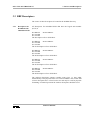
3.3 RBF Descriptors
The source of these descriptors is located in the IO/RBF directory.
3.3.1
Descriptors for
Harddisk with
embedded SCSI
All descriptors for embedded SCSI disk have the logical unit number
(LUN) 0.
h0.embscsi
h0.scsi256
h0.scsi512
dd.h0.embscsi
The descriptors refer to SCSI ID 6.
h1.embscsi
h1.scsi256
h1.scsi512
dd.h1.embscsi
The h1 descriptors refer to SCSI ID 5.
h2.embscsi
h2.scsi256
h2.scsi512
dd.h2.embscsi
The h2 descriptors refer to SCSI ID 2.
h3.embscsi
h3.scsi256
h3.scsi512
dd.h3.embscsi
The h3 descriptors refer to SCSI ID 3.
h4.embscsi
h4.scsi256
h4.scsi512
dd.h4.embscsi
The h4 descriptors refer to SCSI ID 4.
The embscsi descriptors support variable sector sizes, i.e. they adapt
automatically to the physical sector size on the harddisk. The scsi256 and
scsi512 descriptors have a fixed sector size and may be used for physical
formatting. In normal operation the embscsi descriptors should be used.
Software Manual
15
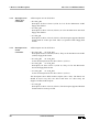
3 Drivers and Descriptors
3.3.2
Descriptors for
TEAC FC-1
Controller
OS-9 V2.4 on EUROCOM-17
All descriptors are for SCSI ID 3.
• d0.teac_3ms
Descriptor for drive select 0 (LUN 0). It is for the Microware 38W7
floppy disk format.
• u0.teac_3ms
Descriptor for drive select 0 (LUN 0). It is for the Microware universal
floppy disk format.
• s0.teac_HD
Descriptor for drive select 0 (LUN 0). The descriptor supports HD disk
format with 32 sectors per track. This is a special ELTEC floppy disk
format.
3.3.3
Descriptors for
SCFL
Controller
All descriptors are for SCSI ID 1.
• d0.scfl_3ms
d0.scfl_6ms
Descriptors for drive select 0 (LUN 0). They are for the Microware 58W7
(38W7) floppy disk format.
• d1.scfl_3ms
d1.scfl_6ms
As the d0 descriptors but for drive select 1 (LUN 1).
• u0.scfl_3ms
u0.scfl_6ms
Descriptors for drive select 0 (LUN 0). They are for the Microware
universal floppy disk format.
• u1.scfl_3ms
u1.scfl_6ms
As the u0 descriptors but for drive select 1 (LUN 1).
The descriptors above differ in their steprate (3ms / 6ms). The fastest one
should be used. Very old 5.25" drives and some 3.5" drives may not
support 3 milliseconds steprate.
• s0.scfl_HD
Descriptor for drive select 0 (LUN 0). The descriptor supports HD disk
format with 32 sectors per track.
16
Software Manual
OS-9 V2.4 on EUROCOM-17
3 Drivers and Descriptors
3.4 SCF Drivers and Descriptors
• scrmon
Depending on the setup of the RMon, the VGA monitor/AT-keyboard or
one of the serial channels may be used as console. The console is
implemented as SCF device with the device driver scrmon, which
operates in polling mode. The console device descriptor name is always
term.
Using scrmon makes sure that the OS-9 configuration adapts to the
RMon configuration.
• sc17cons
This is the interrupt driven driver for the MF-2 keyboard and the
graphics. The driver needs a kbset module, so one of the following
modules from /dd/CMDS/BOOTOBJS has to be loaded:
kbset_us
kbset_ger
kbset_mgr
kbset_mger
standard US keyboard set
german keyboard set
keyboard set for MGR US layout
keyboard set for MGR german layout
Additionally, the driver needs a font module. Select one of the following
fonts and load it to your module directory from /dd/CMDS/BOOTOBJS:
font_9x18
font_7x14
font_11x20
The resolution and refresh rate of the graphic interface are taken from
RMON’s parameter RAM.
This driver should be default.
i
See appendix A for a detailed description of the control sequence codes.
• sc8x36
Centronics driver for CIO (z8536) on EUROCOM-17.
• sccd2401
Driver for the four serial channels on the EUROCOM-17.
Software Manual
17
3 Drivers and Descriptors
OS-9 V2.4 on EUROCOM-17
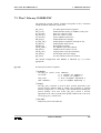
Table 1: Available SCF Descriptors and Appropriate Drivers
Descriptor
Driver
Description
term.rmon
scrmon
Console device depending on RMon setup
term.cons
sc17cons
Interrupt-driven driver for keyboard and graphics
term.t0
sccd2401
Serial channel 0 (RJ11 on front panel)
t0
sccd2401
CD2401 port A (RJ11 on front panel)
t1
sccd2401
CD2401 port B (CHAN.2 on CONV-300)
t2
sccd2401
CD2401 port C (CHAN.3 on CONV-300)
t3
sccd2401
CD2401 port D (CHAN.4 on CONV-300)
pp
sc8x36
Centronics port on z8536
pp1
sc8x36
Centronics port 1 on IPIN-1100 on LEB
pp2
sc8x36
Centronics port 2 on IPIN-1100 on LEB
cons
sc17cons
Same as term.cons
The sources of the descriptors may be found in directory IO/SCF.
18
Software Manual
OS-9 V2.4 on EUROCOM-17
3 Drivers and Descriptors
3.5 SBF Drivers and Descriptors
For each supported streamer there is a driver and an appropriate
descriptor. The following streamers are supported:
Table 2: Available SBF Descriptors and Appropriate Drivers
Driver
Descriptor
Type
sbtandberg
mt0.scsi
TANDBERG 36xx
sbgiga
mt0.wang
WangDAT 2600
sbviper
mt0.viper
ARCHIVE VIPER
sbgiga
mt0.exa
EXABYTE
sbteac
mt0.teac
TEAC MT-2
sbteac
mt0.standard
WANGTEK 5150SE
sbteac
mt0.standard
SANKYO CP-150SE
If the used streamer type is not included in the table, try descriptor
mt0.standard and driver sbteac this should work fine.
The sources of the descriptors are located in directory IO/SBF. All mt0
descriptors are for SCSI ID 2.
3.6 PCF - The PC File Manager
Load the following
/dd/CMDS/BOOTOBJS):
modules
into
memory
(located
in
1. PCF - the PC file manager (located in /dd/PCF/CMDS/BOOTOBJS).
2. RBF driver rbteac/rbcteac , rbscfl/rbcscfl or rbvccs/rbcvccs .
3. The descriptor for your PC-DOS format.
Software Manual
19
3 Drivers and Descriptors
OS-9 V2.4 on EUROCOM-17
The following descriptors are available:
Name
Format
pc0l.scfl_360k
40 tracks, 9 sectors, 5.25"
pc0l.scfl_720k
80 tracks, 9 sectors, 3.5"
pc0h.scfl_12mb
80 tracks,15 sectors, 5.25"
pc0h.scfl_144mb
80 tracks,18 sectors, 3.5"
pc0l.teac_720k
80 tracks, 9 sectors, 3.5"
pc0h.teac_144mb
80 tracks, 18 sectors, 3.5"
pchd.scsi512
Harddisk, SCSI ID 4, 512 B/sector
SCFL floppy descriptors are also available for drive 1.
i
pc0l.scfl_360k enables double stepping on SCFL, so only a 80 track
floppy drive can be used.
Use the partdgen utility to create a descriptor for partitioned harddisks
(see chapter 1-12 in PCF documentation).
4. Now you may use /pc0l for low density and /pc0h for high density
disks.
i
You may create the PCF descriptors by using the rdfdesc.a file in
/dd/IO/RBF.
$ chd /dd/io/rbf
$ make pcf
Restrictions:
•The DCH disk cache can not be used on /pcxx devices.
•ELTEC’s back utility works correctly for /pcxx as destination and file
names restricted to eight characters plus three for extension.
20
Software Manual
OS-9 V2.4 on EUROCOM-17
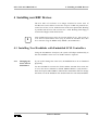
4 Installing new RBF Devices
4 Installing new RBF Devices
The new OS-9 V2.4 release is no longer restricted to sector sizes of
256 B/sector. It now allows sector sizes of up to 32 KB. For practical use,
sector sizes of 256, 512 or 1024 B/sector are the most practicable. Booting
is possible from devices with a sector size ≤ 1024. Booting from floppy is
restricted to floppies with 256 B/sector.
i
Most harddisk descriptors have the Format Inhibit bit set. This results in
error 000:255 (E$Format) when trying to format the harddisk. Reset this
bit in runtime using the dmode utility (dmode /h0 format=on ).
4.1 Installing New Harddisks with Embedded SCSI Controllers
Using the hx.embscsi descriptor, the system will adapt automatically to
the new harddisk's sector size. No further action is required.
4.1.1
Changing the
Sector Size on
SCSI Drives
If you wish to change the sector size, the harddisk has to be re-formatted
physically.
Use hx.scsi256 for a sector size of 256, and hx.scsi512 for a sector size
of 512. The driver transmits a default MODE SELECT (only header +
block descriptor) and FORMAT UNIT SCSI command in order to change
the block size on the harddisk. This should work fine with most harddisks.
Software Manual
21
4 Installing new RBF Devices
OS-9 V2.4 on EUROCOM-17
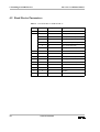
4.2 Fixed Device Parameters
Table 3: Used SCSI IDs on EUROCOM-17
SCSI-ID
LUN
Descriptor
0
1
2
3
22
Type
<none>
0
d0
SCFL (ELTEC format)
1
d1
SCFL (ELTEC format)
0
s0
SCFL (ELTEC high density format)
1
s1
SCFL (ELTEC high density format)
0
u0
SCFL (universal format)
1
u1
SCFL (universal format)
0
mt0
Streamer
h2
Harddisk
d0
TEAC (ELTEC format)
s0
TEAC (high density format)
u0
TEAC (universal format)
h3
Harddisk
0
4
0
h4
Harddisk
5
0
h1
Harddisk
6
0
h0
Harddisk
Software Manual
OS-9 V2.4 on EUROCOM-17
5 Features and Enhancements
5 Features and Enhancements
This chapter describes the changes in the ELTEC dependent part of the
software since the V2.3 release.
5.1 Sysgo
The sysgo /systs modules
profile utility to proceed
are rewritten in C. Sysgo now uses the
the startup file. As a consequence the
environment variables for the initial shell may be set in the startup file.
Sysgo also executes the script file /dd/SYS/ .login_default to set the
default environment.
5.2 Init
- System Identification Some software packages developed by ELTEC (OS9TCP, COMU-200)
used to read the MainFram string (M$Instal) located in the init module in
order to identify the CPU board. Problems arose, when customers began
to change this string, so ELTEC had to find a solution to overcome
potential problems: the init module contains a field named M$Site,
which was not used in the past, but now holds a unique board
identification code. This field must not be changed!!!
The SiteCode for the EUROCOM-17 is $45313700.
ELTEC's software packages now proceed by the following strategy:
The software reads the MainFram string, which defaults to ‘ELTEC
Eurocom X’. If the string has not been changed, it sufficiently identifies
the board. If it has been changed, the software reads the ’Site’code to
identify the board. This way there will be no problems in terms of
compatibility with older versions of OS-9.
Software Manual
23
5 Features and Enhancements
24
OS-9 V2.4 on EUROCOM-17
Software Manual
OS-9 V2.4 on EUROCOM-17
6 Additional Utilities
6 Additional Utilities
6.1 Dmode Utility
As an addition to the Microware utilities, ELTEC delivers this utility to
examine or change RBF descriptors in runtime (like xmode for SCF
descriptors).
❏ Syntax:
dmode [<opts>] /<device> [<parameters>] [<opts>]
❏ Options:
-?
List usage
❏ Parameters: (prefix hex values with $)
drive=<n>
RBF logical drive number
type=hard|floppy drive type
size=5|8
disk size (use 5 for 3.5)
dens=s|d
data density (single or double)
tk0dens=s|d
data density on track 0 (single or double)
heads=<n>
number of data surfaces
cyls=<n>
number of cylinders (including spares)
trkdens=s|d
track density (on floppies)
scttrk=<n>
physical sectors per track (including spares)
scttk0=<n>
sectors per track on track 0, if tk0dns=s
ssize=<n>
physical sector size
unit=<n>
unit number (used by controller)
ctlid=<n>
SCSI controller ID
step=<n>
step rate code
verify=on|off
verify by read after write
seg=<n>
minimum segment allocation size
ilv=<n>
physical interleave factor
toffs=<n>
track base offset
soffs=0|1
first physical sector on each track
format=on|off
enable/inhibit logical and physical formatting
multsct=on|off
enable/disable multi-sector transfers
autosiz=on|off
use/don't use SS_DSize GetStat call during format
trkfmt=on|off
enable/inhibit single track formatting
tries=<n>
number of attempts on read/write (1 = no retries)
wpc=<n>
first cylinder with write precompensation
rwr=<n>
first cylinder with reduced write current
park=<n>
cylinder to park heads on
Software Manual
25
6 Additional Utilities
OS-9 V2.4 on EUROCOM-17
lsnoffs=<n>
disconn=on|off
sync=on|off
maxcnt=<n>
offset to first logical sector
enable/disable SCSI disconnect/reselect
enable/disable synchronous transfer
max. transfer count (0 = default = 64K)
6.2 Back Utility
Back
is ELTEC's special backup utility for general backup purposes.
❏ Syntax:
back [<opts>] <source> [<destination>] [<opts>]
❏ Description:
Back is used to backup/restore directory trees to/from disk or tape.
Back may be used instead of dsave and fsave /frestore .
If the destination device is a disk, you may backup the directories
either in OS-9 structure (like using the dsave utility) or in a streamer
like structure called saveset, using a special raw mode, which works
much faster.
The '-l' (list) and '-v' (verify) options are useful to manage the saveset.
The '-z' (exclude), '-o' (include) and '-i' (date) options avoid useless
copying, by defining special conditions for the files to be copied.
If there is no more space on the device, back will prompt for a new
disk/tape to continue. The name of saveset’s parts on the additional
output volumes are labeled with a sequence number, which is not
considered as a part of the name.
When using a streamer, back needs a device descriptor loaded into
memory before operation. Starting from OS-9 V2.4, back uses the mt0
SBF descriptor as default tape descriptor.
26
Software Manual
OS-9 V2.4 on EUROCOM-17
6 Additional Utilities
The following streamer types are supported:
mt0.scsi
for the Tandberg 3620/40/60 Streamers
mt0.exa
for the ExaByte 8200
mt0.teac
for the Teac MT-2ST Streamer
mt0.viper
for the Archive Viper Tapes
mt0.standard
for the WangTek 5150SE and Sankyo CP-150SE
mt0.wang
for the WangDat 2600
Default destination device can be set with the shell environment
parameter BACK_DEV, otherwise it is /mt0.
❏ Caveats:
If the source is a saveset, the destination must not be a saveset. If the
output device runs out of free space during a saveset restore operation
back cannot call for a new volume to continue.
There are problems with Tandberg TDC 3660 streamers with ROM
Revision 4.00 and writing more than one saveset to tape. In some cases
the streamer will hang.
The underscore character '_' is not allowed in saveset name.
Be sure that the specified volume size is smaller than or equal to
volume capacity.
i
There are two different versions of back , one for old ELTEC drivers and
one for original Microware drivers. At this time Microware drivers are
used on EUROCOM-17 only.
❏ Options:
-s=<filename>
Specifies source/destination saveset name for disk.
-t[=<filename>] Specifies source/destination saveset name for tape. If
no filename/device is specified, back uses the default
tape device mt0 and the name save_1.
-i=<date>
Only files with a more recent date than specified in
<date> are treated.
Format of <date>: dd.mm.yy[-hh.mm]
Software Manual
27
6 Additional Utilities
OS-9 V2.4 on EUROCOM-17
-z[=<filename>] Reads an exclude list. None of the files/
subdirectories in this list will be treated. Note that the
full pathname of each file/directory is required.
Wildcards ('*','?') are accepted. If <filename> is
given, back will read the exclude list from
<filename>, otherwise it will be read from the
standard input path. Input from standard input path
can be terminated by <ESC>.
-o[=<filename>] Reads a select list. Only the files/subdirectories
included in this list will be treated. For more details,
see the '-z' option.
-f[=<filename>] Formats destination device. <Filename> is the name
of a command file, which is forked by back .
This file has to contain a command line like:
format /d0 -npnvnfr . The default command file is
/dd/SYS/format.back. Tapes should always be
erased prior writing first saveset.
-b=<num>
Allocates <num> KB of memory for copying. Back
uses 100 KB by default.
-p
Asks before copying.
-q
Doesn't ask before copying (default).
-x
Debug mode
-l
Lists names of the files in the saveset.
(Works only on saveset)
-v
Verifies the files in the saveset.
(Works only on saveset)
-a
Writes a saveset in block mode.
-c
Fills last block to complete buffer size.
-k
Doesn’t overwrite existing files (copy and rename
first).
The following options only make sense if destination is not a saveset.
-r
28
Writes over existing destination file with same name
without asking.
Software Manual
OS-9 V2.4 on EUROCOM-17
6 Additional Utilities
-n
Asks if existing destination file with same name shall
be overwritten. (default)
-u
Update mode. Only sources with a more recent
creation date than existing destination are treated.
Add '-r' option if for automatic update.
The following options only work on tapes.
-w
Rewinds the tape before reading or writing. Use this
if you are not sure about the saveset position on the
tape. If this option is not specified, the saveset will be
written behind the last saveset on tape.
-e=<volume_size> Specifies volume size for tape in KB.
Defaults are:
120 MB for mt0.scsi
(Tandberg 36XX)
2048 MB for mt0.exa
(ExaByte 8200)
120 MB for mt0.teac
(Teac MT-2ST)
120 MB for mt0.viper' (Archive Viper)
120 MB for mt0.standard (WangTek 5150SE/
Sankyo CP-150SE)
3000 MB for mt0.wang
(WangDat 2600)
❏ Examples:
a) Make backups on disks maintaining the OS-9 file structure:
$ back /h0/SOURCES
/d0/SOURCES.back
-r -u
copies all files and directories from /h0/SOURCES to
/d0/SOURCES.back and writes over existing files with same names
if they are older than the source files to copy ('-r' '-u'). The file
structure of /d0/SOURCES.back will be the same as in
/h0/SOURCES.
Back
$ back /h0/SOURCES
/d0/SOURCES.back -f -i=17.10.86
formats the disk in /d0 ('-f'), using the /dd/SYS/format.back
command file and then copy all files/directories which have a more
recent date than 17.10.86 ('-i=') from /h0/SOURCES to
/d0/SOURCES.back.
Back
Software Manual
29
6 Additional Utilities
OS-9 V2.4 on EUROCOM-17
b) Make backups on disks using a saveset:
$ back /h0/SOURCES -s=/d0/savesource >/h0/backout&
copies all files from /h0/SOURCES into one saveset named
savesource on disk. The saveset will be copied into the root
directory of /d0. In this case back will work in the background and
redirect standard output to /h0/backout.
Back
$ back /h0/SOURCES
-s=/d0/savesource -z=exclude
The file exclude may contain the following lines:
"/h0/oldprog"
"/h0/PROGS/*.c"
"*/CMDS/*"
copies all files from /h0/SOURCES into savesource, except
for /h0/oldprog, all C files in PROGS and the files in all CMDS
subdirectories.
Back
c) Make backups on tapes:
$ back /h0 -wft
copies all files from device /h0 into the saveset save_1 on
streamer device mt0. Prior to writing to the tape, it will be erased.
That is the way to backup to a tape without data on it.
Back
$ back /h0/SOURCES -t=/h3/savesource
copies all files from /h0/SOURCES into the saveset on tape.
The file is written to the end of data area.
Back
$ back -t=/h3/savesource
/h1/SOURCES
-w
rewinds the tape ('-w') and restores the files on
/h1/SOURCES. The original file structure will be rebuilt.
Back
$ back /dd -t=/mt0/harddisk -wv
rewinds the tape and compares all files stored in saveset
'harddisk' with files on device /dd.
Back
30
Software Manual
OS-9 V2.4 on EUROCOM-17
7 Additional Libraries
7 Additional Libraries
7.1 The F$System System Call
The F$System system call has been added by ELTEC to provide boardhardware specific functions to the user.
The functions are available to the members of group 0 only.
To keep the number of new system calls to a minimum, all ELTECspecific functions are accessible through the F$System call. A function
code is passed in register d0.w to indicate the operation desired. Specific
parameters and functions of each system operation are discussed in the
following sections. Actual values are resolved by linking with the library
in directory /dd/LIB named libeltec.l for programs written in assembly
language or clibeltec.l for programs written in C.
i
When the system comes up after booting, the SysTrap module checks if it
runs on the right hardware. It does this by analyzing the SiteCode located
in the init module. For correct functioning this field must contain the
unique board identification code of the CPU board, i.e. $45313700.
Software Manual
31
7 Additional Libraries
OS-9 V2.4 on EUROCOM-17
7.2 The Assembler Library LIBELTEC
The following section contains the complete description of the functions
included with the F$System system call:
Sys$IOS
Sys$VMECCtl
Sys$DSCtrl0
Sys$DSCtrl1
Sys$ASCtrl0
Sys$BlkDisp
Sys$EnSemIRQH
Sys$EnAbort
Sys$AutoBoot
Sys$SlavAddr
Sys$BlkMove
Sys$AlignPtr
Sys$SetDisp
Sys$GetSwt
Get mmu-protected I/O segment
Enable/Disable caching of VMEbus read cycles
Data size control 0 (A32)
Data size control 1 (A24)
Select VMEbus AM source
Enable/disable hex display
Enable/disable semaphore interrupt at $7C
Enable/disable abort switch
Read autoboot jumper
Set VMEbus slave base address
VMEbus block transfer via VIC
Align pointer to 256 byte boundary
Set digit of hex display
Get contents of hex switches
The default configuration after RESET is indicated by a (*) where
appropriate.
32
Software Manual
OS-9 V2.4 on EUROCOM-17
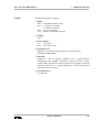
Sys$IOS
7 Additional Libraries
Get mmu-protected I/O segment
❏ Input:
d0.w = 0 (Sys$IOS function code)
d1.l = 1: request I/O segment
0: return I/O segment
d2.l = size of I/O segment
(a0) = address of segment requested
❏ Output:
none
❏ Error Output:
cc =
carry bit set
d1.w = error code if error
❏ Possible Errors:
E$Permit - you must belong to group 0 to use this function
E$MemFull, E$NoRAM
❏ Function:
is used in systems equipped with a paged memory
management unit (PMMU) and thereby using the system security
module (SSM). This function enables group 0 user programs to perform
memory mapped I/O, i.e. writing patterns into a video RAM located
outside the process memory.
Sys$IOS
❏ Cross Reference:
see F$Permit
Software Manual
33
7 Additional Libraries
Sys$VMECCtl
OS-9 V2.4 on EUROCOM-17
Enable/disable caching of VMEbus read cycles
❏ Input:
d0.w = 1 (Sys$VMECCtl function code)
d1.l = 1: enables caching
0: disables caching (*)
-1: read status only
❏ Output:
d0.l
= status
❏ Error Output:
cc =
carry bit set
d1.w = error code if error
❏ Possible Errors:
E$Permit - you must belong to group 0 to use this function
❏ Function:
Sys$VMECCtl enables or disables the cache for VMEbus longword read
cycles. If d1.l equals -1, no action takes place. The status of this
function is always returned in d0.
❏ Note:
The VMEbus caching is allowed for aligned longword read cycles
(A32, D32) only.
34
Software Manual
OS-9 V2.4 on EUROCOM-17
Sys$DSCtrl0
7 Additional Libraries
Data size control 0 (A32)
❏ Input:
d0.w = 2 (Sys$DSCtrl0 function code)
d1.l = 1: A32/D16 transfers
0: A32/D32 transfers (*)
-1: read status only
❏ Output:
d0.l = Status
❏ Error Output:
cc
= carry bit set
d1.w = error code if error
❏ Possible Errors:
E$Permit - you must belong to group 0 to use this function
❏ Function:
sets the data size on the VMEbus during master access at
the address range $0040.0000 - $EFFF.FFFF.
If d1.l equals -1, no action takes place. The status of this function is
always returned in d0.
Sys$DSCtrl0
Software Manual
35
7 Additional Libraries
Sys$DSCtrl1
OS-9 V2.4 on EUROCOM-17
Data size control 1 (A24)
❏ Input:
d0.w = 3 (Sys$DSCtrl1 function code)
d1.l = 1: A24/D32 transfers
0: A24/D16 transfers (*)
-1: read status only
❏ Output:
d0.l = Status
❏ Error Output:
cc =
carry bit set
d1.w = error code if error
❏ Possible Errors:
E$Permit - you must belong to group 0 to use this function
❏ Function:
Sys$DSCtrl1 sets the data size on the VMEbus during master access at
the address range $FF00.0000 - FFFE.FFFF.
If d1.l equals -1, no action takes place. The status of this function is
always returned in d0.
36
Software Manual
OS-9 V2.4 on EUROCOM-17
Sys$ASCtrl0
7 Additional Libraries
Select VMEbus AM source
❏ Input:
d0.w = 4 (Sys$ASCtrl0 function code)
d1.l = 1: the AM source register of the VIC is used to generate the
address modifier code on the VMEbus.
0: extended AM code is generated for address range from
$0040.0000 - $EFFF.FFFF, standard AM code at the
address range $FF00.0000 - $FFFE.FFFF and a short AM
code at addresses $FFFF.0000 - $FFFF.FFFF. (*)
-1: read status only
❏ Output:
d0.l = Status
❏ Error Output:
cc =
carry bit set
d1.w = error code if error
❏ Possible Errors:
E$Permit - you must belong to group 0 to use this function
❏ Function:
If d1.l equals -1, no action takes place. The status of this function is
always returned in d0.
Software Manual
37
7 Additional Libraries
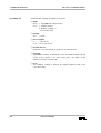
Sys$BlkDisp
OS-9 V2.4 on EUROCOM-17
Enable/disable hex display
❏ Input:
d0.w = 6 (Sys$BlkDisp function code)
d1.l = 1: enables hex display (*)
0: disables hex display
-1: read status only
❏ Output:
d0.l = Status
❏ Error Output:
cc =
carry bit set
d1.w = error code if error
❏ Possible Errors:
E$Permit - you must belong to group 0 to use this function
❏ Function:
Sys$BlkDisp controls the Blank input of the hex display at the front
panel.
If d1.l equals -1, no action takes place. The status of this function is
always returned in d0.
38
Software Manual
OS-9 V2.4 on EUROCOM-17
Sys$EnSemIRQH
7 Additional Libraries
Enable/disable semaphore interrupt at $7C
❏ Input:
d0.w = 7 (Sys$EnSemIRQH function code)
d1.l = 1: enables semaphore IRQ at address $7C (*)
0: disables semaphore IRQ at address $7C
-1: read status only
❏ Output:
d0.l = Status
❏ Error Output:
cc =
carry bit set
d1.w = error code if error
❏ Possible Errors:
E$Permit - you must belong to group 0 to use this function
❏ Function:
only controls the hardware to enable/disable the
semaphore IRQ at address $7C. However, the user still is responsible
for programming any associated port hardware and/or IRQ handlers. If
d1.l equals -1, no action takes place. The status of this function is
always returned in d0.
Sys$EnSemIRQH
Software Manual
39
7 Additional Libraries
Sys$EnAbort
OS-9 V2.4 on EUROCOM-17
Enable abort switch
❏ Input:
d0.w = 8 (Sys$EnAbort function code)
d1.l = 1: enables abort switch (*)
0: disables abort switch
-1: read status only
❏ Output:
d0.l = Status
❏ Error Output:
cc =
carry bit set
d1.w = error code if error
❏ Possible Errors:
E$Permit - you must belong to group 0 to use this function
❏ Function:
If d1.l equals -1, no action takes place. The status of this function is
always returned in d0.
Sys$AutoBoot
Read autoboot setting
❏ Input:
d0.w = 9 (Sys$Autoboot function code)
❏ Output:
d0.w = 0: autoboot disabled
1: autoboot enabled
❏ Error Output:
cc =
carry bit set
d1.w = error code if error
❏ Possible Errors:
E$Permit - you must belong to group 0 to use this function
40
Software Manual
OS-9 V2.4 on EUROCOM-17
Sys$SlavAddr
7 Additional Libraries
Set VMEbus slave base address
❏ Input:
d0.w = 10 ( Sys$SlavAddr function code)
d1.l = VMEbus slave address for standard access
d2.l = VMEbus slave address for extended access
❏ Output:
none
❏ Error Output:
cc =
carry bit set
d1.w = error code if error
❏ Possible Errors:
E$Permit - you must belong to group 0 to use this function.
E$Param - impossible address given
❏ Function:
Sys$SlavAddr sets the VMEbus slave base address for both standard
and extended addressing.
Software Manual
41
7 Additional Libraries
Sys$BlkMove
OS-9 V2.4 on EUROCOM-17
VMEbus block transfer via VIC
❏ Input:
d0.w = 11 (Sys$BlkMove function code)
d1.l = transfer length in bytes
d2.l = bit 0 = 0: write to slave
bit 0 = 1: read from slave
a0.l = pointer to local buffer
a1.l = pointer to target buffer
❏ Output:
none
❏ Error Output:
cc =
carry bit set
d1.w = error code if error
❏ Possible Errors:
E$Permit - you must belong to group 0 to use this function
E$Param - either of the given addresses is not aligned properly (see
below)
E$BadSiz - The transfer count is not divisible by 4.
E$BusErr - A bus error occurred on local or VMEbus
❏ Function:
This function initiates a block transfer between a VMEbus master and
slave. Both master and slave MUST be supplied with a VIC068 chip.
The data width for block transfers is 32-bit (longword) only, so the
given transfer length must be a number divisible by four. To minimize
software overhead, both pointers MUST be 256 byte aligned.
42
Software Manual
OS-9 V2.4 on EUROCOM-17
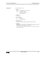
Sys$AlignPtr
7 Additional Libraries
Align pointer to 256 byte boundary
❏ Input:
d0.w = 12 ( Sys$AlignPtr function code)
d1.l = pointer to memory block
❏ Output:
d0.l = the given pointer aligned to the next 256 byte boundary
❏ Error Output:
cc =
carry bit set
d1.w = error code if error
❏ Possible Errors:
E$Permit - you must belong to group 0 to use this function
❏ Function:
Normally, a pointer to a memory block is returned by a 'Request
Memory' function. It will be aligned in any way suitable for the
operating system. Some applications (i.e. Sys$BlkMove ) require a
256 byte alignment of all pointers. To do this, the user should issue a
memory request of the amount needed PLUS 256 bytes used for the
alignment. The pointer returned by the OS is then used by
Sys$AlignPtr .
Software Manual
43
7 Additional Libraries
Sys$SetDisp
OS-9 V2.4 on EUROCOM-17
Set digit of hex display
❏ INPUT:
d0.w = 13 (Sys$SetDisp function code)
d1.l = Digit for hex display
❏ Output:
none
❏ Error Output:
cc =
carry bit set
d1.w = error code if error
❏ Possible Errors:
E$Permit - you must belong to group 0 to use this function
E$Param - impossible value for hex display
❏ Function:
Sys$SetDisp writes the value of d1.l into the boards hex display,
which is located at the front panel. This function returns -1 if the board
does not have a hex display.
Sys$GetSwt
Get contents of hex switches
❏ Input:
d0.l = 13 (Sys$SetDisp function code)
❏ Output:
d0.l = contents of two hex switches
❏ Error Output:
cc =
carry bit set
d1.w = error code if error
❏ Possible Errors:
E$Permit - you must belong to group 0 to use this function
❏ Function:
reads the contents of the hex switches of the board, which
is located at the front panel. The lower switch is located in the lower
nibble of the long word.
Sys$GetSwt
44
Software Manual
OS-9 V2.4 on EUROCOM-17
7 Additional Libraries
7.3 The C Library CLIBELTEC
The following section contains complete description of the C functions
included with the F$System system call:
get_ios()
vme_cctl()
ds_cntrl0()
ds_cntrl1()
as_cntrl0()
blk_disp()
en_sem_irq()
en_abort()
autoboot()
slave_addr()
blk_move()
align_ptr()
set_disp()
get_swt()
Get mmu-proctected I/O segment
Enable/disable caching of VMEbus read cycles
Data size control 0 (A32)
Data size control 1 (A24)
Select VMEbus AM source
Enable/disable hex display
Enable/disable semaphore interrupt at $7C
Enable/diable abort switch
Read autoboot jumper
Set VMEbus slave base address
VMEbus block transfer via VIC
Align pointer to 256 byte boundary
Set the digit of the hex display
Get the contents of the hex switches
The default configuration after RESET is indicated by a (*) where
appropriate.
get_ios()
Get mmu-protected I/O segment
❏ Synopsis:
int get_ios (cntrl, size, address)
int cntrl;
/* 1: request I/O segment */
/* 0: return I/O segment */
long size;
/* size of segment requested */
char *address;
/* ptr to segment beginning */
❏ Usage:
The get_ios() function is used in OS-9 systems protected by the
system security module (SSM ) to enable user programs to perform
memory mapped I/O, i.e. accessing a video RAM located outside the
process memory. If an error occurs, get_ios() returns -1 and the
appropriate error code is placed in the global variable errno. If no error
occurs, get_ios() returns zero.
❏ See Also:
F$System system call, F$Permit
Software Manual
45
7 Additional Libraries
vme_cctl()
OS-9 V2.4 on EUROCOM-17
Enable/disable caching of VMEbus READ cycles
❏ Synopsis:
int vme_cctl (cntrl)
int cntrl;
/* 1: enables caching */
/* 0: disables caching (*) */
/* -1: read status only */
❏ Usage:
The vme_cctl() function controls the cache for VMEbus longword
read cycles. This is allowed for aligned longword read cycles (A32,
D32) only. If an error occurs, vme_cctl() returns -1 and the
appropriate error code is placed in the global variable errno. If no error
occurs, vme_cctl() returns the current status.
❏ See Also:
F$System system call
ds_cntrl0()
Data size control 0 (A32)
❏ Synopsis:
int ds_cntrl0 (cntrl)
int cntrl;
/* 1: A32/D32 transfers (*) */
/* 0: A32/D16 transfers
*/
/* -1: read status only
*/
❏ Usage:
The ds_cntrl0() function is used to control the data size on the
VMEbus during master access at the address range from $0040.0000 $EFFF.FFFF.
If an error occurs, ds_cntrl0() returns -1 and the appropriate error
code is placed in the global variable errno. If no error occurs,
ds_cntrl0() returns the current status.
❏ See Also:
F$System system call
46
Software Manual
OS-9 V2.4 on EUROCOM-17
ds_cntrl1()
7 Additional Libraries
Data size control 1 (A24)
❏ Synopsis:
int ds_cntrl1 (cntrl)
int cntrl;
/* 1: A24/D32 transfers
*/
/* 0: A24/D16 transfers (*) */
/* -1: read status only
*/
❏ Usage:
The ds_cntrl1() function sets the data size on the VMEbus during
master access at the address range from $FF00.0000 - $FFFE.FFFF.
If an error occurs, ds_cntrl1() returns -1 and the appropriate error
code is placed in the global variable errno. If no error occurs,
ds_cntrl1() returns the current status.
❏ See Also:
F$System system call
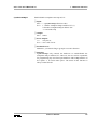
as_cntrl0()
Select VMEbus AM source
❏ Synopsis:
int as_cntrl0 (cntrl)
int cntrl;
/* see below */
❏ Usage:
The as_cntrl0() function selects the source for generation of the AM
code during VMEbus access.
cntrl = 1: the AM source register of the VIC is used to generate the
AM code on the VMEbus
cntrl = 0: extended AM code is generated for address range
(*) from $0040.0000 - $EFFF.FFFF, standard AM code at the
address range $FF00.0000 - $FFFE.FFFF and short AM
code at $FFFF.0000 - $FFFF.FFFF.
cntrl = -1: read status only
If an error occurs, as_cntrl0() returns -1 and the appropriate error
code is placed in the global variable errno. If no error occurs,
as_cntrl0() returns the current status.
❏ See Also:
F$System system call
Software Manual
47
7 Additional Libraries
blk_disp()
OS-9 V2.4 on EUROCOM-17
Enable/disable hex display
❏ Synopsis:
int blk_disp (cntrl)
int cntrl;
/* 1: enables hex display (*) */
/* 0: disables hex display
*/
/* -1: read status only
*/
❏ Usage:
The blk_disp() function enables or disables the hex display at the
front panel.
If an error occurs, blk_disp() returns -1 and the appropriate error
code is placed in the global variable errno. If no error occurs,
blk_disp() returns the current status.
❏ See Also:
F$System system call
en_sem_irq()
Enable/disable semaphore interrupt at $7C
❏ Synopsis:
int en_sem_irq (cntrl)
int cntrl;
/* 1: enables semaphore interrupt (*) */
/* 0: disables semaphore interrupt */
/* -1: read status only */
❏ Usage:
The en_sem_irq() function enables or disables semaphore interrupts
at address $7C.
If an error occurs, en_sem_irq() returns -1 and the appropriate error
code is placed in the global variable errno. If no error occurs,
en_sem_irq() returns the current status.
❏ See Also:
F$System system call
48
Software Manual
OS-9 V2.4 on EUROCOM-17
en_abort()
7 Additional Libraries
Enable abort switch
❏ Synopsis:
int en_abort(cntrl)
int cntrl;
/* 1: enables abort switch (*) */
/* 0: disables abort switch
*/
/* -1: read status only
*/
❏ Usage:
The en_abort() function enables or disables the abort switch at the
front panel.
If an error occurs, en_abort() returns -1 and the appropriate error
code is placed in the global variable errno. If no error occurs,
en_abort() returns the current status.
❏ See Also:
F$System system call
autoboot()
Read autoboot setting
❏ Synopsis:
int autoboot()
❏ Usage:
The autoboot() function reads the autoboot jumper configuration.
If an error occurs, autoboot() returns -1 and the appropriate error
code is placed in the global variable errno. If no error occurs,
autoboot() returns zero if autoboot is disabled, and a one if autoboot
is enabled.
❏ See Also:
F$System system call
Software Manual
49
7 Additional Libraries
slave_addr()
OS-9 V2.4 on EUROCOM-17
Set VMEbus slave base address
❏ Synopsis:
int slave_addr (std_addr, ext_addr)
unsigned std_addr; /* VMEbus addr. for standard access */
unsigned ext_addr; /* VMEbus addr. for extended access */
❏ Usage:
The slave_addr() function sets the VMEbus slave base address for
both standard and extended addressing.
If an error occurs, slave_addr() returns -1 and the appropriate error
code is placed in the global variable errno. If no error occurs,
slave_addr() returns zero.
❏ See Also:
F$System system call
blk_move()
VMEbus block transfer via VIC
❏ Synopsis:
int blk_move (count, mode, mbuf, sbuf)
unsigned count;
short mode;
long *mbuf;
long *sbuf;
/*
/*
/*
/*
/*
Transfer length in bytes
*/
0 = write to slave
*/
1 = read from slave
*/
pointer to buffer on master */
pointer to buffer on slave */
❏ Usage:
The blk_move() function initiates a block transfer between a VMEbus
master and slave. Both master and slave MUST be supplied with a
VIC068 chip. The data width for block transfers is 32 bit (longword)
only, so the given transfer length must be a number divisible by four.
To minimize software overhead, both pointers MUST be 256 byte
aligned. If an error occurs, blk_move() returns -1 and the appropriate
error code is placed in the global variable errno. If no error occurs,
blk_move() returns zero.
❏ See Also:
F$System system call
50
Software Manual
OS-9 V2.4 on EUROCOM-17
align_ptr()
7 Additional Libraries
Align a given pointer to a 256 byte boundary
❏ Synopsis:
long *align_ptr (pointer)
long *pointer;
❏ Usage:
Normally, a pointer to a memory block is returned by a 'Request
Memory' function, e.g. malloc() . It will be aligned in any way suitable
for the operating system. Some applications (i.e. blk_move() ) require
a 256-byte alignment of all pointers. To do this, the user should issue a
memory request of the amount needed PLUS 256 bytes used for the
alignment. The pointer returned by the OS is then used by
align_ptr() .
❏ See Also:
F$System system call
set_disp()
Set digit of hex display
❏ Synopsis:
int blk_move (digit)
unsigned digit;
/* Digit for hex display */
❏ Usage:
This function writes the value of 'digit' into the boards hex display.
❏ See Also:
F$System system call
get_swt()
Return the contents of the boards hex switches
❏ Synopsis:
int get_swt()
❏ Usage:
Returns the contents of the boards hex switches, which are located at
the front panel. The contents of the lower hex switch is located in the
lower nibble of the return value.
❏ See Also:
F$System system call
Software Manual
51
7 Additional Libraries
52
OS-9 V2.4 on EUROCOM-17
Software Manual
OS-9 V2.4 on EUROCOM-17
Appendix A: Control Sequence Codes
Appendix A: Control Sequence Codes
ANSI Standard Terminal Emulation
The sc17cons output character functions for the graphic interface
emulates a subset of a standard ANSI X3.64 terminal.
The sc17cons displays 24 lines of 80 ASCII characters per line (default
setting), with scrolling, (x, y) cursor addressability, and some other
control functions. The non-blinking block cursor marks the current line
and character position on the screen. When one of the ASCII characters
between $20 (space) and $FF are written to the screen by calling the
sc17cons (and the character is not part of an escape sequence), it is
displayed at the current cursor position and the cursor moves one position
to the right on the current line. If the cursor is already at the right edge of
the screen, it moves to the first character position on the next line. If the
cursor is already at the right edge of the screen on the bottom line, the
screen is scrolls up by one line, before moving the cursor to the first
character position on the next line.
Control Sequence Syntax
The sc17cons output function defines a number of control sequences
which may occur in its input. When such a sequence is written to the
sc17cons output function, it is not displayed on the screen, but effects
some control function as described below.
Some of the control sequences consist of a single character. The notation
<CTRL>-x
for some character x, represents a control character.
Other ANSI control sequences are of the form
CSI <params> <char> or < ESC> [ <params> char
Spaces are included only for readability. These characters must occur in
the given sequence without the intervening spaces.
Software Manual
53
Appendix A: Control Sequence Codes
<ESC>
[
<params>
<char>
CSI
OS-9 V2.4 on EUROCOM-17
represents the ASCII escape character
(<ESC>, <Ctrl>-[, $1B).
The next character is a left square bracket '[' ($5B).
are a sequence of zero or more decimal numbers made up of
digits between 0 and 9, separated by semicolons.
represents a function character which is different for each
control sequence.
represents the ANSI control sequence introducer ($9B).
‘<ESC> [’ and CSI are alternate representations of the ANSI ‘Control
Sequence Introducer’and may replace each other in any situation.
Some examples of syntactically valid escape sequences are:
<ESC> [ m
<ESC> [ 2 A
<ESC> [ 10;5 H
select graphic rendition with default parameter
moves cursor 2 lines up
set cursor position
Supported Control Codes
•<CTRL>-H ($08) Backspace <BS>
The cursor moves one position to the left on the current line. If it is
already at the left edge of the screen, nothing happens.
•<CTRL>-J ($0A) Line-feed <LF>
The cursor moves down one line, remaining at the same character
position on the line. If the cursor is already at the bottom line, the screen
scrolls up one line.
•<CTRL>-M ($0D) Return <CR>
The cursor moves to the leftmost character position on the current line.
Supported ANSI Control Sequences
The syntax of the sequences follows the ANSI terminal standard, i.e.
arguments are to be given as readable ASCII strings, using decimal
notation, and are to be separated by semicolons. In the following
arguments will be indicated by short names enclosed in angle brackets.
Printing characters in the range '@'..'~' are regarded as terminating codes.
If they are defined in the following, they start processing the respective
function. Undefined terminating codes simply abort the sequence without
any action taken.
54
Software Manual
OS-9 V2.4 on EUROCOM-17
Appendix A: Control Sequence Codes
If a syntactical error is found within a sequence, the sc17cons output
function skips all input until a terminating code is encountered, which
results in a return to the normal not-in-sequence state.
•<ESC> [ <n> A
Cursor Up (CUU)
Takes one parameter, <n> (default 1). Moves the cursor up <n> lines. If
the cursor is fewer than <n> lines from the top of the screen, moves the
cursor to the topmost line on the screen. The character position of the
cursor on the line is unchanged.
•<ESC> [ <n> B
Cursor Down (CUD)
Takes one parameter, <n> (default 1). Moves the cursor down <n> lines.
If the cursor is fewer than <n> lines from the bottom of the screen, moves
the cursor to the last line on the screen. The character position of the
cursor on the line is unchanged.
•<ESC> [ <n> C
Cursor Forward (CUF)
Takes one parameter, <n> (default 1). Moves the cursor right by <n>
character positions on the current line. If the cursor is fewer than <n>
positions from the right edge of the screen, moves the cursor to the
rightmost position on the current line.
•<ESC [ <n> D
Cursor Backward (CUB)
Takes one parameter, <n> (default 1). Moves the cursor left by <n>
character positions on the current line. If the cursor is fewer than <n>
positions from the left edge of the screen, moves the cursor to the
leftmost position on the current line.
•<ESC> [ <lin>;<col> H Cursor Position (CUP)
Takes two parameters, <lin> and <col> (default 1, 1). Moves the cursor
to the line <lin> and the character position <col>. Character positions are
numbered from 1 at the left edge of the screen; line positions are
numbered from 1 at the top of the screen.
•<ESC> [ J
Erase in Display (ED)
Takes no parameter. Erases from the current cursor position inclusive to
the end of the screen. The cursor position is unchanged.
•<ESC> [ K
Erase in Line (EL)
Takes no parameters. Erases from the current cursor position inclusive to
the end of the current line. The cursor position is unchanged.
•<ESC> [ <n> L
Insert Line (IL)
Takes one parameter, <n> (default 1). Makes room for <n> new lines
starting at the current line by scrolling down by <n> lines the portion of
the screen from the current line inclusive to the bottom. The <n> new
lines at the cursor are filled with spaces. The bottom <n> lines shift off
the bottom of the screen and are lost. The position of the cursor on the
screen is unchanged.
Software Manual
55
Appendix A: Control Sequence Codes
OS-9 V2.4 on EUROCOM-17
•<ESC> [ <n> M
Delete Line (DL)
Takes one parameter, <n> (default 1). Delete <n> beginning with the
current line. The portion of the screen from the current line inclusive to
the bottom is scrolled upwards by <n> lines. The <n> new lines scrolling
onto the bottom of the screen are filled with spaces. The <n> old lines
beginning at the cursor line are deleted. The position of the cursor on the
screen is unchanged.
•<ESC> [ <sel> m
Select Graphic Rendition (SGR)
Takes one parameter, <sel> (default 0). Invokes the graphic rendition
specified by the parameter. All following printing characters in the data
stream are rendered according to the parameter until the next occurrence
of this escape sequence. Only two graphic renditions are defined.
0 Normal rendition
7 Reverse video mode on
•<ESC> ? <sel> h
Takes one parameter, <sel>. Turns on private feature specified by the
parameter. Only one private feature is defined.
25 Cursor On (visible)
•<ESC> ? <sel> l
Takes one parameter, <sel>. Turns off private feature specified by the
parameter. Only one private feature is defined.
25 Cursor Off (invisible)
56
Software Manual