1
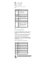
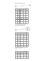
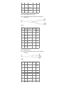
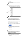
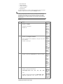
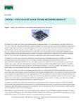
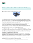
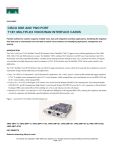
Cisco AS5800 Series Universal Gateways Cisco AS5800 Access Server Channelized T1/E1 Trunk Cards HOME SUPPORT PRODUCT SUPPORT ENDOFSALE AND ENDOFLIFE PRODUCTS CISCO AS5800 SERIES UNIVERSAL GATEWAYS CONFIGURE CONFIGURATION GUIDES Cisco AS5800 Access Server Channelized T1/E1 Trunk Cards Table Of Contents Downloads Cisco AS5800 Access Server Cisco AS5800 Universal Access Channelized T1/E1 Trunk Cards Server Channelized T1 or E1 Trunk Card Installation and Replacement Document Contents Feedback If You Need More Information Cisco AS5800 Universal Access Server Overview CT1 and CE1 Trunk Card Overview LED Indicators CT1 and CE1 Trunk Card Port Monitoring Trunk Card Bantam Jacks Specifications CT1 and CE1 Trunk Card Port Pinout CT1 Trunk Card Cables and Pinouts CE1 Trunk Card Cables and Pinouts Online Insertion and Removal Safety Guidelines Telephone Wiring Guidelines Preventing Electrostatic Discharge Damage Safety Warnings Removing and Replacing a Trunk Card Tools and Parts Required Removing a Trunk Card Replacing a Trunk Card Connecting Trunk Card Cables Configuring Cable Length Verifying and Troubleshooting the Installation Configuring the CT1 and CE1 Trunk Card FCC Compliance Cisco Connection Online Cisco AS5800 Universal Access Server Channelized T1 or E1 Trunk Card Installation and Replacement Product Number: DS5812CT1=, DS5812CE1= The Cisco AS5800 Universal Access Server supports channelized T1 (CT1) and channelized E1 (CE1) ingress interfaces that provide a synchronous telecommunication interface in both North American and international environments. The CT1 or CE1 trunk card is installed in the Cisco 5814 dial shelf in the Cisco AS5800 Universal Access Server. This document explains how to remove and replace a CT1 or CE1 trunk card in the Cisco 5814 dial shelf chassis. It also includes steps for verifying and troubleshooting your trunk card installation. Note Use this document in conjunction with the Cisco AS5800 Universal Access Server Hardware Installation and Configuration Guide and the Cisco AS5800 Universal Access Server Software Installation and Configuration Guide that shipped with your system. Document Contents The following sections are included in this document: • If You Need More Information • Cisco AS5800 Universal Access Server Overview • CT1 and CE1 Trunk Card Overview • Online Insertion and Removal • Safety Guidelines • Removing and Replacing a Trunk Card • Verifying and Troubleshooting the Installation • Configuring the CT1 and CE1 Trunk Card • Cisco Connection Online If You Need More Information For information regarding the Cisco AS5800 Universal Access Server that is beyond the scope of this document or for additional information, use the following resources: use the following resources: • For Cisco AS5800 Universal Access Server hardware installation and maintenance information, refer to the Cisco AS5800 Universal Access Server Hardware Installation and Configuration Guide (Document Number DOCAS5800HICG=) that shipped with your system. • For Cisco AS5800 Universal Access Server software installation and configuration, refer to the Cisco AS5800 Universal Access Server Software Installation and Configuration Guide (Document Number DOCAS5800SICG=) that shipped with your system. • For international agency compliance, safety, and statutory information for widearea network (WAN) interfaces for the Cisco AS5800 Universal Access Server, refer to the document Cisco AS5800 Universal Access Server Regulatory Compliance and Safety Information (Part Number 784666xx) that shipped with your system. • To obtain general information about documentation, refer to the section "Cisco Connection Online," or call customer service at 800 5536387, or 408 5267208. Customer service hours are 5:00 a.m. to 6:00 p.m., Pacific time, Monday through Friday (excluding Ciscoobserved holidays). You can also send email to cs [email protected], or you can refer to the Cisco Information Packet that shipped with your system. • Cisco Documentation CDROM package Cisco documentation and additional literature are available in a CDROM package, which ships with your product. The Documentation CDROM, a member of the Cisco Connection Family, is updated monthly; therefore, it might be more current than printed documentation. To order additional copies of the Documentation CDROM, contact your local sales representative or call customer service. The CDROM package is available as a single package or as an annual subscription. You can also access Cisco documentation on the World Wide Web at http://www.cisco.com, http://wwwchina.cisco.com, or http://www europe.cisco.com. If you are reading Cisco product documentation on the World Wide Web, you can submit comments electronically. Click Feedback on the toolbar, and then select Documentation. After you complete the form, click Submit to send it to Cisco. We appreciate your comments. • For additional Cisco IOS software information, refer to the following modular configuration and modular command reference publications, as appropriate for your configuration: • Configuration Fundamentals Configuration Guide • Configuration Fundamentals Command Reference • Dial Solutions Configuration Guide • WideArea Networking Configuration Guide • WideArea Networking Command Reference • Network Protocols Configuration Guide • Network Protocols Command Reference • Configuration Builder Getting Started Guide • Troubleshooting Internetworking Systems • Debug Command Reference • System Error Messages • Cisco IOS Software Command Summary • Cisco Management Information Base (MIB) User Quick Reference Cisco AS5800 Universal Access Server Overview The Cisco AS5800 Universal Access Server is a highdensity, ISDN and modem WAN aggregation system that provides both digital and analog call termination. It is intended to be used in service provider dial pointofpresence (POP), or centralized enterprise dial environments. The access server chassis components include a Cisco 5814 dial shelf and a Cisco 7206 router shelf. An optional AC power shelf is also available. The dial shelf and router shelf are bundled, and can be ordered to support either AC or DC power. Included in the dial shelf is a blower assembly, filter module, and power entry modules (PEMs). Also included in the bundled system are ingress trunk cards, modem cards, dial shelf controller cards, Flash memory PCMCIA cards, cables, and Cisco IOS software. The dial shelf feature cards and host router shelf communicate via a dial shelf interconnect cable. The dial shelf contains 14 slots (numbered 0 through 13 on the backplane) and can support up to 10 modem cards, 2 CT1 or CE1 trunk cards, and 2 dial shelf controller cards (in the near future). Only slots 0 through 5 are designed to recognize trunk cards and are prioritized for clock selection beginning with slot 0; therefore, you must install trunk cards in the first six slots. The router shelf supports the dial shelf and performs all routing and The router shelf supports the dial shelf and performs all routing and packet processing. The router shelf also houses the main system software images. shows a front view of a fully configured Cisco AS5800 Universal Access Server, and shows a rear view. Figure 1 Cisco AS5800 Universal Access Server—Front View Figure 2 Cisco AS5800 Universal Access Server—Rear View CT1 and CE1 Trunk Card Overview Channelized ingress interfaces reside on either CT1 or CE1 trunk cards that are installed in the Cisco 5814 dial shelf. A CT1 or CE1 trunk card contains all necessary functionality to terminate incoming telephone calls. The channelized trunk card is configured in the factory for either T1 or E1 framing, depending on your order. shows the CT1 and CE1 trunk card components. Figure 3 CT1 and CE1 Trunk Card The CT1 and CE1 trunk cards perform the following functions: • Terminate up to 12 T1 or 12 E1 lines The CE1 trunk card provides physical termination for up to 12 E1 lines and connects to an external network termination (NT1) device, while the CT1 trunk card provides physical termination for up to 12 T1/Primary Rate Interface (PRI) lines, includes channel service units (CSUs), and connects directly to the telco network. • Demultiplex DS0s A framer removes framing and embedded signaling bits (or inserts them depending on the direction of the flow), and the framer CPU sends the data stream to onboard time division multiplexing (TDM) resources, which break out each call (DS0) and pass each call to an appropriate call termination resource. Digital or ISDN originated calls are terminated onboard the CT1 or CE1 trunk card on Highlevel Data Link Control (HDLC) controllers, and analog modemoriginated calls are passed over the dial shelf backplane TDM bus to an available modem resource. The system software controls modem and HDLC resource management. • Respond to timesensitive signaling Each individual T1 or E1 port can be used as the system clocking Each individual T1 or E1 port can be used as the system clocking reference. Each CT1 or CE1 trunk card can supply two clocks from any two of its twelve ports. You can assign priorities to these clocks, or accept the default values assigned by the software. Default values for clocking are based on the following parameters: (a) Ports are prioritized from 011. The port with the lowest number has the highest priority. (b) Slots are prioritized from slot 0 to slot 5. The lowest slot number has the highest priority. (c) Clocks are prioritized by slot number. The highest priority clock is selected from the card in slot 0. If this clock fails, the highest priority clock from the card in slot 1 becomes the default clock, and so forth. The trunk card then forwards the clocks to the dial shelf controller. The dial shelf controller selects the highest priority clock as the system primary clock, and the rest of the clocks remain in a prioritized backup queue. Instead of using the default algorithm for clock selection, you can specify clocks through configuration. You configure the clocks globally, and can select a maximum of two clocks per trunk card. For example, if you install three trunk cards, you can configure up to six clocks. (While two trunk cards are sufficient to give full coverage to ten modem cards, you can have up to six trunk cards seated in slots 0 through 5 for a maximum selection of twelve clocks.) If you configure fewer than two clocks on a trunk card and all other configured clocks fail, the clock selection will resort to the default algorithm on that card and the second clock will be selected automatically. • Process counting information for performance monitoring • Support online insertion and removal (OIR) The trunk card supports OIR, a feature that allows you to remove and replace trunk cards in the Cisco 5814 dial shelf while the system is operating without disrupting other cards and their associated calls. If you remove a trunk card while the system is operating, all calls associated with the 12 E1 or T1 lines on that card are dropped. Calls being handled by other trunk or modem cards, however, are not affected. shows two trunk cards installed in a fully configured Cisco 5814 dial shelf chassis. Figure 4 Cisco 5814 Dial Shelf Chassis Fully Configured with Trunk Cards Installed LED Indicators The CT1 and CE1 trunk card front panel is designed with LED indicators and a liquid crystal display (LCD) to provide trunk card status and portlevel monitoring information. shows the trunk card LEDs. Figure 5 CT1 and CE1 Trunk Card Front Panel LEDs There are two types of LEDs for the T1 and E1 trunk cards: • Cardlevel LEDs, which provide status information for card maintenance • Portassociated LEDs, which provide warning signals and configuration status on a perport basis. All LEDs are visible from the front panel. (See .) lists the CT1 and CE1 trunk card LEDs and their functions. Table 1 CT1 and CE1 Trunk Card LED Descriptions Indicator Color PWR (Power OK) Green Lights when 5V power is active. Description Maint Yellow Lights when there are no (Maintenance) active calls on the card and you have completed a card level software busyout. Indicates the card is ready to be removed. E1FR (E1 Framing) Green E1 trunk card only. Lights when the card is configured for E1 framing. T1FR (T1 Framing) Green T1 trunk card only. Lights when the card is configured for T1 framing. HCPU (Host CPU OK) Green Lights when the host CPU is operating normally. FCPU (Framer Green Lights when the framer CPU is CPU OK) operating normally. CT1 and CE1 Trunk Card Port Monitoring The CT1 and CE1 trunk card front panels are designed with a liquid crystal display (LCD) to provide trunk card status and portlevel monitoring information (see and ). The current port number displayed in the LCD also corresponds to the four portassociated LEDs. describes the portassociated LEDs and their functions. Table 2 CT1 and CE1 Trunk Card PortAssociated LEDs Indicator Color Description Indicator Color LALM (Local Alarm) Yellow Lights when an alarm condition is detected on incoming data. Description RALM (Remote Alarm) Yellow Lights when the associated E1 port has detected loss of signal (LOS) or out of frame (OOF) errors. This occurs when the remote LIU1 receives errors and sends a signal to indicate presence of remote errors. 75 (Ohm) Green E1 trunk card only. ON indicates 75 ohms, and OFF indicates 120 ohms. NLOOP Yellow Lights when the port is configured (Network in network loopback. This is useful Loopback) for testing purposes. 1 LIU = line interface unit (analog physical interface). Refers to circuitry that interfaces a serial communications circuit to a transmission medium such as coaxial cabling. Trunk Card Bantam Jacks Passive port monitoring is supported through two shared bantam jacks located at the bottom of the trunk card front panel (see ). The bantam jacks allow you to connect a network monitoring device to the trunk card to detect T1 or E1 errors. The 4character LCD indicates which of the 12 T1 or E1 lines are to be monitored or inspected using the bantam jacks. To enable the bantam jacks for port monitoring, follow these steps: Step 1 Push and quickly release the pushbutton (labeled monitor #) below the LCD to toggle to the port number you want to display. You must release the button within two seconds to advance through the port numbers (from 0 to 11). After port 11, the display returns to port 0. As you advance through the port numbers, the portassociated LEDs reflect the configuration status and alarm conditions of the port number displayed in the LCD. Step 2 Push and hold the monitor button for two or more seconds to enable the bantam jack. To disable the bantam jack and return to toggle mode, press the button again and hold it for two or more seconds. When you release the button, the port no longer toggles through the port numbers, the letter "B" is displayed in the LCD, and the bantam jacks are enabled. Step 3 Repeat Step 1 and Step 2 to enable the bantam jacks for each port you wish to monitor. Figure 6 CT1 and CE1 Trunk Card Front Panel LCD and Bantam Jacks Specifications lists the CT1 and CE1 trunk card specifications. Table 3 Description Specification Dimensions 15.4 x .08 x 18.7 in. (39.12 x .203 x 47.5 H x W x L cm) without the carrier 15.5 x 1.23 x 19 in. (39.37 x 3.12 x 48.26 cm) with the carrier Weight 8 lb (3.6 kg) Transmission bit rate: T1 E1 1.544 Mbps 2.048 megabits per second (Mbps) Power 48 VDC (power consumption: 3.3 VDC requirements and 5 VDC) Regulatory compliance: T1 E1 AT&T Accunet TR 62411 specifications; JATE1 T9863040; PanEuro CE0168 X ACA TS001, A53260; JATE N98N019 0; Sweden 98031130; Singapore ISDN2IPTAAE 034598; Singapore DLCN1MBPSAO034498 ; UK 607122 1 JATE = Japan Approval Telecommunication Equipment. CT1 and CE1 Trunk Card Specifications CT1 and CE1 Trunk Card Port Pinout The CT1 trunk card receives and transmits 1.544Mbps signals through a 100ohm cable, using common RJ45 connectors. Use a straight through RJ45toRJ45 cable to connect the T1 lines to an RJ45 receptacle. The CE1 trunk card receives and transmits 2.048Mbps CE1 signals through either 120ohm or 75ohm coaxial cable. All CE1 interface cables use common RJ45 connectors on the dial shelf end. The receive impedance is software configurable and may be configured as 75 ohms or 120 ohms. The T1 default value is 100 ohms. The E1 default value is 120 ohms. Use the line termination {75ohm | 120ohm} command in controller configuration mode to configure the receive impedance. lists the CT1 and CE1 port pinouts. Table 4 CT1 and CE1 Trunk Card Port (RJ45) Pinouts Pin Signal 1 Receive tip 2 Receive ring 3 Jumpered ground 4 Transmit tip 5 Transmit ring 6 Jumpered ground 7 not used 8 not used Warning The ports labeled "Network Clock," "10BaseT," "Dial Shelf Interconnect," "Console," and "Alarms" are safety extralow voltage (SELV) circuits. SELV circuits should only be connected to other SELV circuits. Because the E1/T1 circuits are treated like telephonenetwork voltage, avoid connecting the SELV circuit to the telephone network voltage (TNV) circuits. CT1 Trunk Card Cables and Pinouts One interface cables is available from Cisco Systems for connecting the CT1 card ports; the cable is described in . Table 5 Cable Description Product Number RJ45 to Bare, 100ohm CABT1RJ45BARE CT1 Interface Cables The shows the CT1 interface cable, and describes the pinouts for the CT1 interface cable. Figure 7 RJ45toBare Wire Interface Cable Table 6 RJ45 Pin Signal Description Direction Bare Shield Ground Braid J11 RX Tip Twisted Pair #1 <— WIRE 1 J12 RX Ring Twisted Pair #1 <— WIRE 2 J13 RX Shield J14 TX Tip Twisted Pair #2 —> WIRE 3 J15 TX Ring Twisted Pair #2 —> WIRE 4 J16 TX Shield RJ45toBare Cable Pinouts CE1 Trunk Card Cables and Pinouts Seven interface cables are available from Cisco Systems for connecting the CE1 card ports; these cables and their product numbers are listed in . Table 7 Cable Description Product Number RJ45 to RJ45, 120ohm CABE1RJ45RJ45 RJ45 to DB15, 120ohm CABE1RJ45DB15 RJ45 to DB15 Null, 120ohm CABE1RJ45DB15N RJ45 to BNC, 75ohm CABE1RJ45BNC RJ45 to Twinax, 75ohm CABE1RJ45TWIN RJ45 to RJ45 TE, 120ohm CABE1RJ45TE RJ45 to RJ45 NT, 120ohm CABE1RJ45NT CE1 Interface Cables The following figures and tables illustrate and describe the pinouts for each CE1 interface cable: each CE1 interface cable: Figure 8 RJ45toRJ45 Interface Cable Table 8 RJ45 Pin Signal RJ45 T1 Description Direction Pin Shield Ground Shell/Braid J11 RX Tip Twisted Pair <— #1 J21 J12 RX Ring Twisted Pair <— #1 J22 J13 RX Shield J14 TX Tip Twisted Pair —> #2 J24 J15 TX Ring Twisted Pair —> J25 Shield #2 J16 TX Shield RJ45toRJ45 E1 Cable Pinouts (Crossover) Figure 9 RJ45toDB15 Interface Cable Table 9 RJ45 Pin Signal Description DB15 Direction Pin Shield Ground Shell/Braid Shell J11 RX Tip Twisted Pair #1 <— J23 J12 RX Ring Twisted Pair #1 <— J211 J13 RX Shield Twisted Pair #3 J24 J14 TX Tip Twisted Pair #2 —> J21 J15 TX Ring Twisted Pair #2 —> J29 J16 TX Shield Twisted Pair #4 J22 RJ45toDB15 Cable Pinouts Table 10 RJ45 Pin Signal Description DB15 Direction Pin Shield Ground Shell/Braid Shell J11 RX Tip Twisted Pair #1 <— J21 J12 RX Ring Twisted Pair #1 <— J29 J13 RX Shield J22 Twisted Pair #3 J14 Shield #3 TX Tip Twisted Pair —> J23 #2 J15 TX Ring Twisted Pair #2 —> J211 J16 TX Shield Twisted Pair #4 J24 RJ45toDB15 Null Modem Cable Pinouts Figure 10 RJ45toBNC Interface Cable for 75Ohm, Unbalanced Connections Table 11 RJ45 Pin Signal Shield Ground Shell J11 RX Tip Twisted Pair <— #1 RXTip J12 RX Ring Twisted Pair <— #1 RXShield J13 RX Shield Twisted Pair #3 RXShield J14 TX Tip Twisted Pair —> #2 TXTip J15 TX Ring Twisted Pair —> #2 J16 TX Shield Description Direction BNC Pin Twisted Pair #4 RX, TX Shields TXShield TXShield RJ45toBNC Cable Pinouts Figure 11 RJ45toTwinax Interface Cable for 75Ohm, Unbalanced Connections Table 12 RJ45 Pin Signal Description Direction Twinax Pin Shield Ground Shell J11 RX Tip Twisted Pair <— #1 RX1 J12 RX Ring Twisted Pair <— #1 RX2 J13 RX Shield Twisted Pair #3 RX Shield J14 TX Tip Twisted Pair —> #2 TX1 J15 TX Ring Twisted Pair —> #2 TX2 J16 TX Shield Twisted Pair #4 RX, TX Shields TX Shield Shield #4 RJ45toTwinax Cable Pinouts Figure 12 RJ45toRJ45 Interface Cable Table 13 RJ45 Pin Signal RJ45 TE Description Direction Pin Shield Ground Shell/Braid J11 RX Tip Twisted Pair <— #1 J21 J12 RX Ring Twisted Pair <— #1 J22 J13 RX Shield Twisted Pair #3 J23 J14 TX Tip Twisted Pair —> #2 J24 J15 TX Ring Twisted Pair —> #2 J25 J16 TX Shield Twisted Pair #4 Shield J26 RJ45toRJ45 TE Cable Pinouts (Straightthrough) Table 14 RJ45 Pin Signal Description Direction Signal RJ45 NT Pin Shield Ground Shell/Braid Ground Shield J11 RX Tip Twisted Pair #1 <— TX Tip J24 J12 RX Ring Twisted Pair #1 <— TX Ring J25 J13 RX Shield Twisted Pair #3 TX Shield J26 J14 TX Tip Twisted Pair #2 —> RX Tip J21 J15 TX Ring Twisted Pair #2 —> RX Ring J22 J16 TX Shield Twisted Pair #4 RX Shield J23 RJ45toRJ45 NT Cable Pinouts (Crossover) Warning The ports labeled "Network Clock," "10BaseT," "Dial Shelf Interconnect," "Console," and "Alarms" are safety extralow voltage (SELV) circuits. SELV circuits should only be connected to other SELV circuits. Because the E1/T1 circuits are treated like telephonenetwork voltage, avoid connecting the SELV circuit to the telephone network voltage (TNV) circuits. Online Insertion and Removal The Cisco AS5800 Universal Access Server supports online insertion and removal (OIR). This feature allows you to remove and replace a dial shelf controller card or feature card (trunk card or modem card) while the system is operating without affecting system operation. Note This section describes the mechanical functions of the system components and emphasizes the importance of following the correct procedures to avoid unnecessary circuit card failures. This section is for background information only. Refer to the section "Removing and Replacing a Trunk Card" for specific procedures regarding the CT1 and CE1 trunk card. Each dial shelf controller card and feature card contains a female connector with which it connects to a male connector on the system backplane. Each male backplane connector comprises a set of tiered pins, in two lengths. The backplane pins send specific signals to the system as they make contact with the card connectors. The system assesses the signals it receives and the order in which it receives them to determine what event is occurring and what task it needs to perform, such as reinitializing new interfaces or shutting down removed ones. Each dial shelf controller card and feature card is designed with two ejector levers to be used when you install or remove a card (see ). The function of the ejector levers is to align and securely seat the card connectors in the backplane. Caution Do not force the dial shelf controller cards or feature cards into a slot, as this can damage the backplane connector pins if they are not aligned properly with the card connectors. Note To avoid erroneous failure messages, you must allow at least 15 seconds for the system to reinitialize and note current interface configurations before you remove or insert a dial shelf controller card or feature card in the dial shelf. Safety Guidelines This section provides safety and ESDprevention guidelines to help you avoid injury to yourself and avoid damage to the equipment. The following safety guidelines are recommended when working with any equipment that connects to electrical power or telephone wiring: • Locate the emergency poweroff switch for the room in which you are working before beginning any procedures requiring access to the chassis interior. • Never work alone when potentially hazardous conditions exist. • Never assume that power has been disconnected from a circuit; always check. • Never perform any action that creates a potential hazard to people or makes the equipment unsafe. • Carefully examine your work area for possible hazards such as moist floors, ungrounded power extension cables, and missing safety grounds. • This unit is to be installed in a restricted access area in accordance with articles 11016, 11017, and 11018 of the National Electric Code, ANSI/NFPA 70. Telephone Wiring Guidelines The following guidelines are recommended when working with any equipment that is connected to telephone wiring or to other network cabling: • Never install telephone wiring during a lightning storm. • Never install telephone jacks in wet locations unless the jack is specifically designed for wet locations. • Never touch uninsulated telephone wires or terminals unless the telephone line has been disconnected at the network interface. • Always use caution when installing or modifying telephone lines. Preventing Electrostatic Discharge Damage Electrostatic discharge (ESD) damages equipment and impairs electrical circuitry. ESD occurs when printed circuit cards are improperly handled and results in complete or intermittent failures. The system feature cards and dial shelf controller cards consist of a printed circuit board that is fixed in a metal carrier. Electromagnetic interference (EMI) shielding, connectors, and ejector levers are integral components of the carrier. Handle the cards by their carrier edges or ejector levers only; never touch the printed circuitry, card components, or connector pins. Although the metal carrier helps to protect the printed circuitry from ESD, you should wear a preventive antistatic strap whenever handling feature cards or dial shelf controller cards. Ensure that the strap makes good skin contact, and connect the strap's clip to an unpainted chassis surface to safely channel unwanted ESD voltages to ground. The following are guidelines for preventing ESD damage: • Always use an ESD wrist strap or ankle strap when installing or replacing system components. Ensure that the ESD strap makes contact with your skin. • Handle the trunk cards by their metal carrier edges and handles only; avoid touching the printed circuit card components or any connector pins. • Place all system components that have been removed on an antistatic surface with the printed circuit card components facing upward, or in a static shielding bag. If you are returning a feature card to the factory, immediately place it in a static shielding bag. Caution Periodically check the resistance value of the antistatic strap. The measurement should be within the range of 1 and 10 megohms. Safety Warnings Safety warnings appear throughout this publication in procedures that, if performed incorrectly, may harm you. A warning symbol precedes each warning statement. Warning This warning symbol means danger. You are in a situation that could cause bodily injury. Before you work on any equipment, be aware of the hazards involved with electrical circuitry and be familiar with standard practices for preventing accidents. To see translations of the warnings that appear in this publication, refer to the Regulatory Compliance and Safety Information document that accompanied this device. Waarschuwing Dit waarschuwingssymbool betekent gevaar. U verkeert in een situatie die lichamelijk letsel kan veroorzaken. Voordat u aan enige apparatuur gaat werken, dient u zich bewust te zijn van de bij elektrische schakelingen betrokken risico's en dient u op de hoogte te zijn van standaard maatregelen om ongelukken te voorkomen. Voor vertalingen van de waarschuwingen die in deze publicatie verschijnen, kunt u het document Regulatory Compliance and Safety Information (Informatie over naleving van veiligheids en andere voorschriften) raadplegen dat bij dit toestel is ingesloten. Varoitus Tämä varoitusmerkki merkitsee vaaraa. Olet tilanteessa, joka voi johtaa ruumiinvammaan. Ennen kuin työskentelet minkään laitteiston parissa, ota selvää sähkökytkentöihin liittyvistä vaaroista ja tavanomaisista onnettomuuksien ehkäisykeinoista. Tässä julkaisussa esiintyvien varoitusten käännökset löydät laitteen mukana olevasta Regulatory Compliance and Safety Information kirjasesta (määräysten noudattaminen ja tietoa turvallisuudesta). Attention Ce symbole d'avertissement indique un danger. Vous vous trouvez dans une situation pouvant causer des blessures ou des dommages corporels. Avant de travailler sur un équipement, soyez conscient des dangers posés par les circuits électriques et familiarisezvous avec les procédures couramment utilisées pour éviter les accidents. Pour prendre connaissance des traductions d'avertissements figurant dans cette publication, consultez le document Regulatory Compliance and Safety Information (Conformité aux règlements et consignes de sécurité) qui accompagne cet appareil. Warnung Dieses Warnsymbol bedeutet Gefahr. Sie befinden sich in einer Situation, die zu einer Körperverletzung führen könnte. Bevor Sie mit der Arbeit an irgendeinem Gerät beginnen, seien Sie sich der mit elektrischen Stromkreisen verbundenen Gefahren und der Standardpraktiken zur Vermeidung von Unfällen bewußt. Übersetzungen der in dieser Veröffentlichung enthaltenen Warnhinweise finden Sie im Dokument Regulatory Compliance and Safety Information (Informationen zu behördlichen Vorschriften und Sicherheit), das zusammen mit diesem Gerät geliefert wurde. Avvertenza Questo simbolo di avvertenza indica un pericolo. La situazione potrebbe causare infortuni alle persone. Prima di lavorare su qualsiasi apparecchiatura, occorre conoscere i pericoli relativi ai circuiti elettrici ed essere al corrente delle pratiche standard per la prevenzione di incidenti. La traduzione delle avvertenze riportate in questa pubblicazione si trova nel documento Regulatory Compliance and Safety Information (Conformità alle norme e informazioni sulla sicurezza) che accompagna questo dispositivo. Advarsel Dette varselsymbolet betyr fare. Du befinner deg i en situasjon som kan føre til personskade. Før du utfører arbeid på utstyr, må du vare oppmerksom på de faremomentene som elektriske kretser må du vare oppmerksom på de faremomentene som elektriske kretser innebærer, samt gjøre deg kjent med vanlig praksis når det gjelder å unngå ulykker. Hvis du vil se oversettelser av de advarslene som finnes i denne publikasjonen, kan du se i dokumentet Regulatory Compliance and Safety Information (Overholdelse av forskrifter og sikkerhetsinformasjon) som ble levert med denne enheten. Aviso Este símbolo de aviso indica perigo. Encontrase numa situação que lhe poderá causar danos físicos. Antes de começar a trabalhar com qualquer equipamento, familiarizese com os perigos relacionados com circuitos eléctricos, e com quaisquer práticas comuns que possam prevenir possíveis acidentes. Para ver as traduções dos avisos que constam desta publicação, consulte o documento Regulatory Compliance and Safety Information (Informação de Segurança e Disposições Reguladoras) que acompanha este dispositivo. ¡Advertencia! Este símbolo de aviso significa peligro. Existe riesgo para su integridad física. Antes de manipular cualquier equipo, considerar los riesgos que entraña la corriente eléctrica y familiarizarse con los procedimientos estándar de prevención de accidentes. Para ver una traducción de las advertencias que aparecen en esta publicación, consultar el documento titulado Regulatory Compliance and Safety Information (Información sobre seguridad y conformidad con las disposiciones reglamentarias) que se acompaña con este dispositivo. Varning! Denna varningssymbol signalerar fara. Du befinner dig i en situation som kan leda till personskada. Innan du utför arbete på någon utrustning måste du vara medveten om farorna med elkretsar och känna till vanligt förfarande för att förebygga skador. Se förklaringar av de varningar som förkommer i denna publikation i dokumentet Regulatory Compliance and Safety Information (Efterrättelse av föreskrifter och säkerhetsinformation), vilket medföljer denna anordning. Removing and Replacing a Trunk Card Depending on your configuration requirements, you might need to replace existing trunk cards or install new trunk cards in your Cisco 5814 dial shelf. Because the system is designed to recognize trunk cards only when they are installed in the first six slots, you must install trunk cards in slots numbered slots 0 through 5 on the dial shelf backplane. Note The OIR feature allows you to install and remove a trunk card without powering off system power. Refer to the section "Online Insertion and Removal" for a description of OIR. To remove a trunk card without dropping the calls or connections, you must first take the trunk card out of service by using the busyout command to busyout DS0s and modem resources as calls are completed. The busyout command is executed on a per card (slot) basis. The busyout command has the format busyout shelfnumber/slot number, where shelf number is a userdesignated value from 09999, and slot number is 05. The following example shows how to busyout the card in slot 0 on shelf 5: router# busyout 5/0 router# If you are replacing a failed trunk card, we recommend you proceed as follows: 1 Busyout the card 2 Remove the existing card 3 Install the new trunk card in the same slot When replacing a trunk card with a new trunk card of the same type in the same slot, the system software will recognize the new trunk card interfaces and bring them up automatically. No additional configuration is needed. A trunk card installed in any other slot will affect the clocking source. Caution To avoid erroneous failure messages, remove or insert only one trunk card at a time. Also, after inserting or removing a trunk card, allow at least 15 seconds before removing or inserting another trunk card so that the system can reinitialize and note the current configuration of all interfaces. Note The system brings online only interfaces that match the current configuration and were previously configured as up; all other interfaces require that you configure them with the configure command. For require that you configure them with the configure command. For information on the configure command, refer to the Cisco AS5800 Universal Access Server Software Installation and Configuration Guide that shipped with your system. Tools and Parts Required You need the following tools and parts to install or replace a trunk card. If you need additional equipment, contact a service representative for ordering information. • CT1 or CE1 trunk card (DS5812CT1=, DS5812CE1=, respectively) • CT1 or CE1 interface cables (See the sections "CT1 Trunk Card Cables and Pinouts" and "CE1 Trunk Card Cables and Pinouts" for a list of product numbers.) • Cable ties • Your own ESDprevention equipment or the disposable grounding wrist strap included with all upgrade kits, field replaceable units (FRUs), and spares. • Cisco AS5800 Universal Access Server Software Installation and Configuration Guide (DOCAS5800SICG) Removing a Trunk Card To remove a trunk card from the Cisco 5814 dial shelf, complete the following steps: Warning Before opening the chassis, disconnect the telephonenetwork cables to avoid contact with telephonenetwork voltages. Caution Trunk cards weigh 8 lb (3.6 kg) each. Use two hands when removing or replacing a trunk card. To remove a trunk card from the Cisco 5814 dial shelf, follow these steps: Step 1 Note the slot in which the trunk card is installed. If you decide to install the new trunk card in the same slot, this will hasten the installation process. Step 2 Initialize the software busyout procedure by entering the following command in privileged EXEC mode: busyout shelf-number/slot-number Step 3 Verify the yellow maintenance LED lights on the trunk card, which indicates the card is offline and ready to be removed. Step 4 Attach an ESDpreventive wrist strap between you and an unpainted chassis surface. Caution To prevent ESD damage, handle trunk cards by ejector levers and carrier edges only, and use an ESDpreventive wrist strap or other grounding device. Step 5 Disconnect all CT1 or CE1 trunk line cables and secure them out of the way using cable ties, if necessary. Step 6 Using a Number 2 Phillips screwdriver, loosen the panel fasteners at the top and bottom of the trunk card front panel. (See .) Figure 13 Using the Ejector Lever Step 7 Pull either the top or bottom ejector lever away from the trunk card front panel to disengage the trunk card from the backplane connector, as shown in . Caution Always use the ejector levers to disengage or seat trunk cards, modem cards, or dial shelf controller cards in the backplane. Failure to do so can cause erroneous system error messages indicating a card failure. However, do not use the ejector levers to lift or support the weight of the cards. Step 8 Grasp the ejector levers and pull the trunk card partially out of the dial shelf slot until you can grasp the trunk card front panel with one hand. Place your other hand under the trunk card to balance the weight of the card as you pull it out of the slot. (See .) Step 9 Pull the trunk card straight out of the slot. Avoid touching the circuitry or any connector pins. Figure 14 Removing and Replacing the CT1 or CE1 Trunk Card Step 10 Place the removed trunk card on an antistatic mat or foam pad until you are ready to reinstall it in the chassis. If you plan to return the card to the factory, place it in an antistatic bag. This completes the trunk card removal procedure. To install or replace a trunk card, proceed to the section "Replacing a Trunk Card." Replacing a Trunk Card To install the trunk card in the Cisco 5814 dial shelf, follow these steps: Caution Trunk cards weigh 8 lb (3.6 kg) each. Use two hands when removing or replacing a trunk card. Trunk cards weigh 8 lb (3.6 kg) each. Use two hands when removing or replacing a trunk card. Step 1 Ensure your ESDpreventive wrist strap is attached between you and an unpainted chassis surface. Caution To prevent ESD damage, handle trunk cards by ejector levers and carrier edges only, and use an ESDpreventive wrist strap or other grounding device. Step 2 Carefully align the trunk card carrier guides with the top and bottom grooves in the dial shelf slot. Avoid touching the circuitry or any connector pins. Step 3 Slide the trunk card into the slot until the ejector levers make contact with the chassis frame. (See .) Step 4 Seat the trunk card in the backplane by pushing the card firmly until the ejector levers fold in toward the trunk card front panel, and the front panel is flush with the chassis frame. Caution Always use the ejector levers to disengage or seat trunk cards, modem cards, or dial shelf controller cards in the backplane. Failure to do so can cause erroneous system error messages indicating a card failure. However, do not use the ejector levers to lift or support the weight of the cards. Step 5 Tighten the panel fasteners using a Number 2 Phillips screwdriver. This secures the backplane connection and ensures proper EMI shielding. Caution Always tighten the panel fasteners on trunk cards. These fasteners prevent accidental removal and provide proper grounding for the system. Step 6 Repeat Step 2 through Step 5 for any other trunk cards you want to install. Caution To avoid erroneous failure messages, remove or insert only one trunk card at a time. Also, after inserting or removing a trunk card, allow at least 15 seconds before removing or inserting another trunk card so that the system can reinitialize and note the current configuration of all interfaces. Step 7 Install a blank filler card (DS58BLANK=) in all empty card slots to keep the chassis dust free and to maintain proper airflow. Caution To prevent the overheating of internal components, always install blank filler cards in empty slots to maintain the proper flow of cooling air across the cards. This completes the trunk card replacement procedure. Proceed to the section "Connecting Trunk Card Cables" to attach the interface cables. Connecting Trunk Card Cables The CT1 and CE1 trunk cards provide 12 RJ45 receptacles for T1 or E1 lines. To connect T1or E1 lines, follow these steps: Warning The telecommunications lines must be disconnected 1) before unplugging the main power connector and/or 2) while the housing is open. Step 1 Attach the RJ45 end of the T1 or E1 cables directly to the RJ45 receptacles on the trunk card. (See .) Step 2 For T1 cabling, attach the network end of your CT1 cables to your external Step 2 For T1 cabling, attach the network end of your CT1 cables to your external network. Step 3 For E1 cabling, attach the network end of your CE1 cables to your network termination (NT1) device. Warning Hazardous network voltages are present in WAN ports regardless of whether power to the unit is OFF or ON. To avoid electric shock, use caution when working near WAN ports. When detaching cables, detach the end away from the unit first. Figure 15 CT1 and CE1 Trunk Card RJ45 Cable Connections Warning The ports labeled "Network Clock," "10BaseT," "Dial Shelf Interconnect," "Console," and "Alarms" are safety extralow voltage (SELV) circuits. SELV circuits should only be connected to other SELV circuits. Because the E1/T1 circuits are treated like telephonenetwork voltage, avoid connecting the SELV circuit to the telephone network voltage (TNV) circuits. Configuring Cable Length When you configure your CT1 trunk cards, you must include the distance of the cable connected to the feature card. To specify this distance, you must use the cablelength command. No cablelength command is required for CE1 trunk cards. If you change the cable length when installing and cabling a new trunk card, you need to specify cable length in your software configuration. The cablelength command is designed to recognize two basic fixed settings: • Cable Length Short • Cable Length Long Cable Length Short The following cable length short configurations define the length range (in feet), between your Network Access Server (NAS) and your repeater. The cablelength short command includes the following settings: • 133 feet (0133 feet) • 266 feet (134266 feet) • 399 feet (267399 feet) • 533 feet (400533 feet) • 655 feet (534655 feet) Note Although you can specify a cable length from 0 to 655 feet, the hardware only recognizes fixed configuration lengths. For example, if your cable length is 50 feet between your NAS and your repeater, you should configure your cable length using the 133feet setting. If you later change the cable length to 200 feet, you should reconfigure your cable length using the 266feet setting. Cable Length Long The following cable length long configurations define the length range in gain and pulse, between your Network Access Server (NAS) and your repeater. The cablelength long command includes the following gain and pulse arguments: • gain 26 (26db Gain) • gain 26 (26db Gain) • gain 36 (36db Gain) • 15db (15db pulse) • 22.5db (22.5 db pulse) • 7.5db (7.5 db pulse) • 0db (0 db pulse) To configure cable length, you must be in global configuration mode. lists commands to help you configure your CT1 lines using the cablelength command. Note When you configure your system for CT1 lines, you must also include additional commands to define framing, line code, clock source, signaling, etc. For complete instructions on how to configure your trunk card lines, refer to the Cisco AS5800 Universal Access Server Software Installation and Configuration Guide that shipped with your system. Table 15 Step Command 1 AS5800-1> enable Password: password AS5800-1# 2 Description Enter the enable command. Enter your password. You are in privileged EXEC mode when the prompt changes to AS58001#. Enter global configuration mode by Enter configuration commands, one per line. End typing the configure with CNTL/Z. command. The example AS5800-1(config)# is using the terminal configuration option. AS5800-1# configure terminal You are in global configuration mode when the prompt changes to AS5800 1(config)#. 3 Enter AS5800-1(config)# controller t1 shelf/slot/port controller configuration mode to configure your controller port. The controller ports are labeled shelf/slot/0 through shelf/slot/11 on the T3 cards. 4 Enter the controller cablelength cablelength short (133 | 266 | 399 | 533 | 655} short value between 0 and 655 [or] (feet). Enter the controller AS5800-1(config-controller)# cablelength long cablelength {gain 26 | gain 36} {-15 | -22.5 | -7.5 | 0} long value using gain and pulse. AS5800-1(config-controller)# Configuring Channelized T1 Cable Length Configuring Channelized T1 Cable Length This completes the trunk card installation procedure. Proceed to the section "Verifying and Troubleshooting the Installation" to verify the installation. Verifying and Troubleshooting the Installation When you first power ON the access server, all LEDs light while the system runs a series of selftest diagnostics. After the system passes initial diagnostics, all LEDs go off. Later the LEDs light again as described in earlier in this document. To complete the installation, verify the trunk card LEDs operate properly by observing the following LED states: • The power LED is ON. If the power LED remains OFF, verify that the card is seated properly. If the power LED lights on other trunk cards in the dial shelf, try inserting the trunk card in a different slot. If none of the power LEDs lights, check your dial shelf power connections, power entry modules, and ACinput power supplies (if present). • The HCPU LED is ON. If the HCPU LED is OFF but the power LED is ON, the software image might have failed to load onto the card. The dial shelf controller will attempt to reload the software automatically. After a programmed number of attempts to reload the software image have failed, the dial shelf controller will power OFF the trunk card, and all LEDs will shut off. If this happens, assume that the failure is due to defective hardware. Return the card to the factory for replacement. • The FCPU LED is ON. If the FCPU LED is OFF while the HCPU LED is ON, either the hardware is defective or the framer processor software has crashed. To determine if the failure is software related, wait while the dial shelf controller card automatically reloads the card. The autoreload feature on the dial shelf controller card will attempt to reload the software image. If the software fails to reload after the programmed number of times, assume that the failure is due to defective hardware. Return the card to the factory for replacement. For further installation troubleshooting information, refer to the Cisco AS5800 Universal Access Server Hardware Installation and Configuration Guide. If you have any questions, or need assistance, proceed to the section "Cisco Connection Online." Configuring the CT1 and CE1 Trunk Card The Cisco 5814 dial shelf only recognizes CT1 and CE1 trunk cards in slots 0 through 5 within the dial shelf chassis; therefore, you must install trunk cards only in the first six slots. If you are replacing a trunk card in the same slot as the one you just removed, the system automatically recognizes the previous system configuration, and no other configuration is needed. If you are replacing a trunk card in a different slot from the one you just removed, additional configuration is needed. Refer to the Cisco AS5800 Universal Access Server Software Installation and Configuration Guide to configure the CT1 and CE1 interfaces. FCC Compliance Regulatory compliance and safety information for the Cisco AS5800 Universal Access Server is contained in the Regulatory Compliance and Safety Information document that shipped with your system. Cisco Connection Online Cisco Connection Online (CCO) is Cisco Systems' primary, realtime support channel. Maintenance customers and partners can selfregister on CCO to obtain additional content and services. Available 24 hours a day, 7 days a week, CCO provides a wealth of standard and valueadded services to Cisco's customers and business partners. CCO services include product information, software updates, release notes, technical tips, the Bug Navigator, configuration notes, brochures, descriptions of service offerings, and download access to public and authorized files. CCO serves a wide variety of users through two interfaces that are updated and enhanced simultaneously—a characterbased version and a multimedia version that resides on the World Wide Web (WWW). The characterbased CCO supports Zmodem, Kermit, Xmodem, FTP, and Internet email, and is excellent for quick access to information over lower bandwidths. The WWW version of CCO provides richly formatted documents with photographs, figures, graphics, and video, as well as hyperlinks to related information. You can access CCO in the following ways: • WWW: http://www.cisco.com • WWW: http://wwweurope.cisco.com • WWW: http://wwwchina.cisco.com • Telnet: cco.cisco.com • Modem: From North America, 408 5268070; from Europe, 33 1 64 46 40 82. Use the following terminal settings: VT100 emulation; databits: 8; parity: none; stop bits: 1; and connection rates up to 28.8 kbps. For a copy of CCO's Frequently Asked Questions (FAQ), contact cco[email protected]. For additional information, contact cco[email protected]. For additional information, contact cco[email protected]. Note If you are a network administrator and need personal technical assistance with a Cisco product that is under warranty or covered by a maintenance contract, contact Cisco's Technical Assistance Center (TAC) at 800 5532447, 408 5267209, or [email protected]. To obtain general information about Cisco Systems, Cisco products, or upgrades, contact 800 5536387, 408 5267208, or cs[email protected]. 78465402 Information For News & Alerts Support About Cisco Small Business Newsroom Downloads Investor Relations Midsize Business Blogs Documentation Corporate Social Responsibility Service Provider Field Notices Executives Security Advisories Home (Linksys) Industries Contact Cisco Find a Partner Contacts | Developer Network Technology Trends Learning Network Cloud Support Community IPv6 Contacts Communities Mobility Video Portal Open Network Environment Trustworthy Systems Feedback | Help | Site Map | Terms & Conditions | Privacy Statement | Cookie Policy | Trademarks Environmental Sustainability Tomorrow Starts Here Career Opportunities Programs Cisco Powered Financing Options