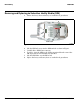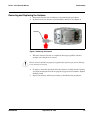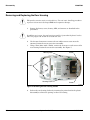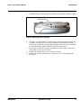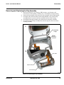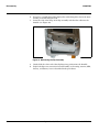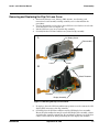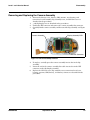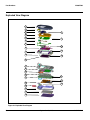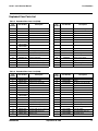
1
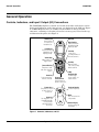
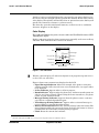
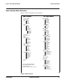
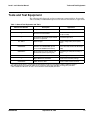
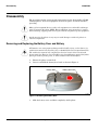
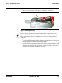
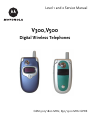
Level 1 and 2 Service Manual V300,V500 Digital Wireless Telephones GSM 900/1800 MHz, 850/1900 MHz GPRS Level 1 and 2 Service Manual 1 and 2 Contents V300/V500 6809468A80 Contents Introduction . . . . . . . . . . . . . . . . . . . . . . . . . . . . . . . . . . . . . . . . . . . . . . . . . . . . . . . . . . . . . . . . . . . . . . . . . . . . . . . . . 5 Product Identification . . . . . . . . . . . . . . . . . . . . . . . . . . . . . . . . . . . . . . . . . . . . . . . . . . . . . . . . . . . . . . . . . . . 5 Product Names . . . . . . . . . . . . . . . . . . . . . . . . . . . . . . . . . . . . . . . . . . . . . . . . . . . . . . . . . . . . . . . . . . . . . . . . 5 Product Changes . . . . . . . . . . . . . . . . . . . . . . . . . . . . . . . . . . . . . . . . . . . . . . . . . . . . . . . . . . . . . . . . . . . . . . . 5 Regulatory Agency Compliance . . . . . . . . . . . . . . . . . . . . . . . . . . . . . . . . . . . . . . . . . . . . . . . . . . . . . . . . . . . 5 Computer Program Copyrights . . . . . . . . . . . . . . . . . . . . . . . . . . . . . . . . . . . . . . . . . . . . . . . . . . . . . . . . . . . 6 About This Service Manual . . . . . . . . . . . . . . . . . . . . . . . . . . . . . . . . . . . . . . . . . . . . . . . . . . . . . . . . . . . . . . 6 Warranty Service Policy . . . . . . . . . . . . . . . . . . . . . . . . . . . . . . . . . . . . . . . . . . . . . . . . . . . . . . . . . . . . . . . . . 7 Parts Replacement . . . . . . . . . . . . . . . . . . . . . . . . . . . . . . . . . . . . . . . . . . . . . . . . . . . . . . . . . . . . . . . . . . . . . 8 Specifications . . . . . . . . . . . . . . . . . . . . . . . . . . . . . . . . . . . . . . . . . . . . . . . . . . . . . . . . . . . . . . . . . . . . . . . . . . . . . . 9 Product Overview . . . . . . . . . . . . . . . . . . . . . . . . . . . . . . . . . . . . . . . . . . . . . . . . . . . . . . . . . . . . . . . . . . . . . . . . . . . 11 Features . . . . . . . . . . . . . . . . . . . . . . . . . . . . . . . . . . . . . . . . . . . . . . . . . . . . . . . . . . . . . . . . . . . . . . . . . . . . . 11 General Operation . . . . . . . . . . . . . . . . . . . . . . . . . . . . . . . . . . . . . . . . . . . . . . . . . . . . . . . . . . . . . . . . . . . . . . . . . . . 14 Controls, Indicators, and Input / Output (I/O) Connections . . . . . . . . . . . . . . . . . . . . . . . . . . . . . . . . . . . . 14 User Interface Menu Structure . . . . . . . . . . . . . . . . . . . . . . . . . . . . . . . . . . . . . . . . . . . . . . . . . . . . . . . . . . 17 Alert Settings . . . . . . . . . . . . . . . . . . . . . . . . . . . . . . . . . . . . . . . . . . . . . . . . . . . . . . . . . . . . . . . . . . . . . . . . 18 Battery Function . . . . . . . . . . . . . . . . . . . . . . . . . . . . . . . . . . . . . . . . . . . . . . . . . . . . . . . . . . . . . . . . . . . . . . 18 Operation . . . . . . . . . . . . . . . . . . . . . . . . . . . . . . . . . . . . . . . . . . . . . . . . . . . . . . . . . . . . . . . . . . . . . . . . . . . . 18 Tools and Test Equipment . . . . . . . . . . . . . . . . . . . . . . . . . . . . . . . . . . . . . . . . . . . . . . . . . . . . . . . . . . . . . . . . . . . . 19 Disassembly . . . . . . . . . . . . . . . . . . . . . . . . . . . . . . . . . . . . . . . . . . . . . . . . . . . . . . . . . . . . . . . . . . . . . . . . . . . . . . . . 20 Removing and Replacing the Battery Door and Battery . . . . . . . . . . . . . . . . . . . . . . . . . . . . . . . . . . . . . . 20 Removing and Replacing the Subscriber Identity Module (SIM) . . . . . . . . . . . . . . . . . . . . . . . . . . . . . . . . 22 Removing and Replacing the Antenna . . . . . . . . . . . . . . . . . . . . . . . . . . . . . . . . . . . . . . . . . . . . . . . . . . . . 23 Removing and Replacing the Rear Housing . . . . . . . . . . . . . . . . . . . . . . . . . . . . . . . . . . . . . . . . . . . . . . . . 24 Removing and Replacing the Battery Tray . . . . . . . . . . . . . . . . . . . . . . . . . . . . . . . . . . . . . . . . . . . . . . . . . 26 Removing and Replacing the Transceiver Board Assembly . . . . . . . . . . . . . . . . . . . . . . . . . . . . . . . . . . . 27 Removing and Replacing the Real-Time Clock (RTC) Battery . . . . . . . . . . . . . . . . . . . . . . . . . . . . . . . . . . 29 Removing and Replacing the Keypad, Volume/Smart and Voice Buttons . . . . . . . . . . . . . . . . . . . . . . . . . 30 Removing and Replacing the Headphone Speaker Connector . . . . . . . . . . . . . . . . . . . . . . . . . . . . . . . . . . 31 Removing and Replacing the Polyphonic Speaker Assembly . . . . . . . . . . . . . . . . . . . . . . . . . . . . . . . . . . . 32 Removing and Replacing the Flip Assembly Cover . . . . . . . . . . . . . . . . . . . . . . . . . . . . . . . . . . . . . . . . . . 33 Removing and Replacing the Flip Assembly . . . . . . . . . . . . . . . . . . . . . . . . . . . . . . . . . . . . . . . . . . . . . . . . 35 Removing and Replacing the Flip CLI Lens Cover . . . . . . . . . . . . . . . . . . . . . . . . . . . . . . . . . . . . . . . . . . . 37 Removing and Replacing the Camera Assembly . . . . . . . . . . . . . . . . . . . . . . . . . . . . . . . . . . . . . . . . . . . . . 39 Removing and Replacing the Motor/Vibrator . . . . . . . . . . . . . . . . . . . . . . . . . . . . . . . . . . . . . . . . . . . . . . . 40 Removing and Replacing the Flip Display Module Assembly . . . . . . . . . . . . . . . . . . . . . . . . . . . . . . . . . . 41 Subscriber Identity Module (SIM) and Identification . . . . . . . . . . . . . . . . . . . . . . . . . . . . . . . . . . . . . . . . . . . . . . . 42 SIM Card . . . . . . . . . . . . . . . . . . . . . . . . . . . . . . . . . . . . . . . . . . . . . . . . . . . . . . . . . . . . . . . . . . . . . . . . . . . . 42 Personality Transfer . . . . . . . . . . . . . . . . . . . . . . . . . . . . . . . . . . . . . . . . . . . . . . . . . . . . . . . . . . . . . . . . . . . 42 Identification . . . . . . . . . . . . . . . . . . . . . . . . . . . . . . . . . . . . . . . . . . . . . . . . . . . . . . . . . . . . . . . . . . . . . . . . . 42 Troubleshooting . . . . . . . . . . . . . . . . . . . . . . . . . . . . . . . . . . . . . . . . . . . . . . . . . . . . . . . . . . . . . . . . . . . . . . . . . . . . 44 Manual Test Mode . . . . . . . . . . . . . . . . . . . . . . . . . . . . . . . . . . . . . . . . . . . . . . . . . . . . . . . . . . . . . . . . . . . . 44 Manual Test Mode Commands . . . . . . . . . . . . . . . . . . . . . . . . . . . . . . . . . . . . . . . . . . . . . . . . . . . . . . . . . . . 44 Troubleshooting Chart . . . . . . . . . . . . . . . . . . . . . . . . . . . . . . . . . . . . . . . . . . . . . . . . . . . . . . . . . . . . . . . . . 46 Programming: Software Upgrade and Flexing . . . . . . . . . . . . . . . . . . . . . . . . . . . . . . . . . . . . . . . . . . . . . . 48 Part Numbers . . . . . . . . . . . . . . . . . . . . . . . . . . . . . . . . . . . . . . . . . . . . . . . . . . . . . . . . . . . . . . . . . . . . . . . . . . . . . . 49 Related Publications . . . . . . . . . . . . . . . . . . . . . . . . . . . . . . . . . . . . . . . . . . . . . . . . . . . . . . . . . . . . . . . . . . . 49 Exploded View Diagram . . . . . . . . . . . . . . . . . . . . . . . . . . . . . . . . . . . . . . . . . . . . . . . . . . . . . . . . . . . . . . . . 50 Exploded View Parts List . . . . . . . . . . . . . . . . . . . . . . . . . . . . . . . . . . . . . . . . . . . . . . . . . . . . . . . . . . . . . . 51 Accessories . . . . . . . . . . . . . . . . . . . . . . . . . . . . . . . . . . . . . . . . . . . . . . . . . . . . . . . . . . . . . . . . . . . . . . . . . . . 53 6809468A80 September 30, 2003 3 Contents 4 V300/V500 September 30, 2003 6809468A80 Level 1 and 2 Service Manual 1 and 2 V300/V500 6809468A80 Introduction Introduction Motorola® Inc. maintains a worldwide organization that is dedicated to provide responsive, full-service customer support. Motorola products are serviced by an international network of company-operated product-care centers as well as authorized independent service firms. Available on a contract basis, Motorola Inc. offers comprehensive maintenance and installation programs that allow customers to meet requirements for reliable, continuous communications. To learn more about the wide range of Motorola service programs, contact your local Motorola products representative or the nearest Customer Service Manager. Product Identification Motorola products are identified by the model number on a label usually located under the battery. Use the entire model number when inquiring about the product. Numbers are also assigned to chassis and kits. Use these numbers when requesting information or ordering replacement parts. Product Names Product names are listed on the front cover. Product names are subject to change without notice. Some product names, as well as some frequency bands, are available only in certain markets. Product Changes When electrical, mechanical or production changes are incorporated into Motorola products, a revision letter is assigned to the chassis or kit affected, for example; -A, -B, or -C, and so on. The chassis or kit number, complete with revision number, is imprinted during production. The revision letter is an integral part of the chassis or kit number and is also listed on schematic diagrams and printed-circuit board layouts. Regulatory Agency Compliance This device complies with Part 15 of the FCC Rules. Operation is subject to the following conditions: • This device may not cause any harmful interference • This device must accept interference received, including interference that may cause undesired operation This class B device also complies with all requirements of the Canadian Interference-Causing Equipment Regulations (ICES-003). Cet appareil numérique de la classe B respecte toutes les exigences du Règlement sur le matériel brouilleur du Canada. 6809468A80 September 30, 2003 5 Introduction 1 and 2 V300/V500 6809468A80 V300/V500 Computer Program Copyrights The Motorola products described in this manual may include Motorola computer programs stored in semiconductor memories or other media that are copyrighted with all rights reserved worldwide to Motorola. Laws in the United States and other countries preserve for Motorola, Inc. certain exclusive rights to the copyrighted computer programs, including the exclusive right to copy, reproduce, modify, decompile, disassemble, and reverse-engineer the Motorola computer programs in any manner or form without Motorola's prior written consent. Furthermore, the purchase of Motorola products shall not be deemed to grant either directly or by implication, estoppel, or otherwise, any license or rights under the copyrights, patents, or patent applications of Motorola, except for a nonexclusive license to use the Motorola product and the Motorola computer programs with the Motorola product. About This Service Manual Use of this manual assures proper installation, operation, and maintenance of Motorola products and equipment. It contains all service information required for the equipment described and is current as of the printing date. Refer questions about this manual to the nearest Customer Service Manager. Audience This manual aids service personnel in testing and repairing V300 and V500 telephones. Service personnel should be familiar with electronic assembly, testing, and troubleshooting methods, and with the operation and use of associated test equipment. Scope This manual provides basic information relating to V300 and V500 telephones, and also provides procedures and processes for repairing the phones at Level 1 and 2 service centers including: • Unit swap out • Repairing of mechanical faults • Basic modular troubleshooting • Testing and verification of unit functionality • Initiate warranty claims and send faulty modules to Level 3 or 4 repair centers 6 September 30, 2003 6809468A80 Level 1 and 2 Service Manual Introduction Conventions The following special characters and typefaces, are used in this manual to emphasize certain types of information. ➧ G E M Note: Emphasizes additional information pertinent to the subject matter. Caution: Emphasizes information about actions which may result in equipment damage. Warning: Emphasizes information about actions which may result in personal injury. Keys to be pressed are represented graphically. For example, instead of “Press the Menu Key”, you will see “Press M”. Information from a screen is shown in text as similar as possible to what displays on the screen. For example, ALERTS or ALERTS. Information that you need to type is printed in boldface type. Warranty Service Policy The product is sold with the standard 12-month warranty terms and conditions. Accidental damage, misuse, and extended warranties offered by retailers are not supported under warranty. Non-warranty repairs are available at agreed fixed repair prices. Out-of-Box Failure Policy The standard out-of-box failure criteria applies. Return customer units that fail very early on after the date of sale to Manufacturing for root cause analysis, to guard against epidemic criteria. Manufacturing to bear the costs of early life failure. Product Support Customer’s original units will be repaired but not refurbished as standard. Appointed Motorola Service Hubs will perform warranty and non-warranty field service for level 2 (assemblies) and level 3 (limited PCB component). Motorola High Tech Centers will perform level-4 (full component) repairs. Customer Support Customer support is available through dedicated Call Centers and in-country help desks. Product Service training is available through the local Motorola Support Center. 6809468A80 September 30, 2003 7 Introduction V300/V500 Parts Replacement When ordering replacement parts or equipment, include the Motorola part number and description used in the service manual. When the Motorola part number of a component is not known, use the product model number or other related major assembly along with a description of the related major assembly and of the component in question. In the U.S.A., to contact Motorola, Inc. on your TTY, call: 800-793-7834. Accessories and Aftermarket Division (AAD) Order replacement parts, test equipment, and manuals from AAD. U.S.A. Outside U.S.A. Phone: 800-422-4210 Phone: 847-538-8023 FAX: 800-622-6210 FAX: 847-576-3023 For EMEA spare parts call + 49 461 803 2690. For Asia spare parts call +65 648 62995. 8 September 30, 2003 6809468A80 Level 1 and 2 Service Manual Specifications Specifications General Function Frequency Range GSM 850 Frequency Range GSM 900 Frequency Range DCS 1800 Frequency Range PCS 1900 Channel Spacing Channels Modulation Transmitter Phase Accuracy Duplex Spacing Frequency Stability Operating Voltage Transmit Current Drain Stand-by Current drain Temperature Range Dimensions, with 500 mAh Li Ion battery Size (Volume) Weight Battery Life, with standard 700 mAh Li-Ion Battery Specification 824-848 MHz Tx 869-893 MHz Rx 880-915 MHz Tx (with EGSM) 925-960 MHZ Rx 1710-1785 MHz Tx 1805-1880 MHz Rx 1850-1910 MHz Tx 1930-1990 MHz Rx 200 kHz 174 EGSM, 374 DCS, 374 PCS, 124 GSM 850 carriers with 8 channels per carrier GMSK at BT = 0.3 5 Degrees RMS, 20 Degrees peak 45 MHz ± 0.10 ppm of the downlink frequency (Rx) +3.2V dc to +5.5V dc (battery) +4.8V dc to +6.5V dc (external connector) 101-260 mA average talk current drain 5 mA (DRX2), 2 mA (DXR9) typical -10° C to +55° C (+15° F to +130° F) 47.3 mm x 87.5 mm x 22.5 mm (1.86 inches x 3.45 inches x 0.89 inches) 75 cc (4.58 in3), with battery 95 grams (3.35 oz), with battery Talk Time 260 to 500 minutes with Blue Tooth off 200 to 320 minutes with Blue Tooth on Standby time 160 to 200 hours with Blue Tooth off 155 to 200 hours with Blue Tooth on Battery Charge Time Alert volume All talk and standby times are approximate and depend on network configuration, signal strength, and features selected. Standby times are quoted as a range from DRX=2 to DRX=9. Talk times are quoted as a range from DTX off to DTX on. 4 hours to 90% of 700 mAh capacity Max 95 dB @5cm, 0.5 Watts input Transmitter Function RF Power Output Output Impedance Spurious Emissions Specification 32 dBm nominal GSM 900, 29 dBm nominal GSM 1800 50 ohms nominal -36 dBm from 0.1 to 1 GHz, -30 dBm from 1 to 4 GHz Receiver Function Receive Sensitivity RX Bit Error Rate (100k bits) Type II Better than -103 dBm < 2% Speech Coding Function Speech Coding Type Bit Rate 6809468A80 Specification Specification Regular pulse excitation/linear predictive coding with long term prediction (RPE LPC with LTP) 13.0 kbps September 30, 2003 9 Specifications Speech Coding Function Frame Duration Block Length Classes Bit Rate with FEC Encoding 10 V300/V500 Specification 20 ms 260 bits Class 1 bits = 182 bits; Class 2 bits = 78 bits 22.8 kbps September 30, 2003 6809468A80 Level 1 and 2 Service Manual Product Overview Product Overview Motorola V300 and V500 telephones are small and lightweight global system for mobile communications (GSM) general packet radio service (GPRS) wireless application protocol (WAP)-enabled mobile phones. The V300 and V500 incorporate a new user interface (UI) for easier operation, allows short message service (SMS) text messaging, and includes personal information manager (PIM) functionality. The V500 is a quad-band phone that allows roaming within the GSM 900 MHz, (DCS) 1800 MHz digital cellular system, the GSM 850 MHz, and PCS 1900 MHz bands. The V300 is a tri-band phone that allows roaming within the GSM 900 MHz, (DCS) 1800 MHz digital cellular system, and the PCS 1900 MHz bands. V300 and V500 telephones support GPRS and SMS in addition to traditional circuit switched transport technologies. V300 telephones have a clam form factor. They feature an anodized aluminum housing and have an externally viewable 96 x 32 pixel display for caller identification and date/time, an internal 176 x 220 pixel display, and the speaker located in the flip. The bottom part of the clam (front housing) contains the keypad, transceiver printed circuit board (PCB), microphone, flex connection, external accessory connector, smart button, volume buttons, and voice button. The standard 650 mAh Lithium Ion (Li Ion) battery fits behind a removable back cover. The phone accepts both 3V and 5V mini subscriber identity module (SIM) cards which fit into the SIM holder underneath the battery. The antenna is a fixed stub type antenna. Inexpensive direct connection to a computer or handheld device via RS232 or USB for data and fax calls, and for synchronizing phonebook entries with TrueSync® software, can be accomplished by using the optional data cable and soft modem. Features V300 and V500 telephones use advanced, self-contained, sealed, custom integrated circuits to perform the complex functions required for GSM GPRS communication. Aside from the space and weight advantage, microcircuits enhance basic reliability, simplify maintenance, and provide a wide variety of operational functions. Features available in this family of telephones include: • GSM 850/900/1800/1900 MHz GPRS (2U/4D) V500 • GSM 900/1800/1900 MHz GPRS (2U4D) V300 • Built in VGA Camera (640x480 pixels) • 64K Thin Film Transistor (TFT) Active Color Display • External CLI Display (Transflective Reversed) • Polyphonic Speaker • Speaker Phone • Bluetooth™ (V500 only) • 5MB User Memory 6809468A80 September 30, 2003 11 Product Overview V300/V500 Speaker Dependant Voice Activation and Voice Note Recording Voice tags can be used for voice dialing up to 20 phone numbers in the phone book and for creating up to 5 voice shortcuts for menu items. The phone must be “trained” by the voice tag being read into the phone’s memory twice before it is recognized. You can add voice tags to the phone’s memory using the usual name addition methods (i.e., via the phone book menu structure or with the shortcut editor). ➧ You cannot place or receive calls while adding voice tags to the phone’s memory. ➧ Because the GSM standard does not provide the option to store voice tags onto the SIM card, voice tags are added to the phone’s memory. V300 and V500 telephones also include a voice note recorder that allows up to 2 minutes of personal messages to be recorded. This feature has a complete set of record, playback, and management tools that make it easy to store and maintain a list of personal memos. Wireless Access Protocol (WAP) 1.1 Compliancy In the WAP environment, access to the Internet is initiated in wireless markup language (WML), which is derived from hypertext markup language (HTML). The request is passed to a WAP gateway which retrieves the information from the server in standard HTML (subsequently filtered to WML) or directly in WML if available. The information is then passed to the mobile subscriber via the mobile network. The V300 and V500’s microbrowser can be configured for baud, idle timeout, line type, phone number, and connection type. ➧ Bitmap image data will download as text. If the image is larger than the screen, only part of the image will display. ➧ When the user receives a call while in browser mode, the browser will pause and allow the user to resume after completing the call. SIM Application ToolkitTM - Class 2 SIM Application Toolkit is a value-added service delivery mechanism that allows GSM operators to customize the services they offer their customers, from the occasional user who requests sports news and traffic alerts, to a high call time business user who receives stock alerts and checks flight times. Operators can now create their own value-added services menu quickly and easily in the phone. The customized menu will appear as the first menu and may be updated over-the-air with new services when customers request them. 12 September 30, 2003 6809468A80 Level 1 and 2 Service Manual Product Overview Simplified Text Entry There are three different ways to enter text using the phone keypad: • iTAP™ predictive text entry. Press a key to generate a character and a dynamic dictionary uses this to build and display a set of word or name options. The iTAP™ feature may not be available on the phone in all languages. • Tap. Press a key to generate a character. • Numeric. The keypad produces numeric characters only. For some text areas this is the only method available; for example, phone numbers. Caller Line Identification Upon receipt of a call, the calling party’s phone number is compared to the phone book. If the number matches a phone book entry, that name will be displayed. If there is no phone book entry, the incoming phone number will be displayed. In the event that no caller identification information is available, the Incoming Call message is displayed. ➧ User must subscribe to a caller line identification service through their service provider. Other Features Detailed descriptions of these and other V300/V500 features can be found in the appropriate user’s guide listed in the “Related Publications” section toward the end of this manual. 6809468A80 September 30, 2003 13 General Operation V300/V500 General Operation Controls, Indicators, and Input / Output (I/O) Connections The V300/V500 telephone’s controls are located on the sides of the device and on the keypad. Indicators, in the form of icons, are displayed on the LCD (see Figure 2). V300/V500 phones have an audible alert transducer on the top and I/O connectors, consisting of a headset jack and an accessory port, located on the top and bottom of the phone. See Figure 1. Headset Jack Insert headset accessory for handsfree use. Menu Key Right Soft Key Perform functions identified by right display prompt. Left Soft Key Perform functions identified by left display prompt. Voice Key Create voice records, phonebook & shortcut names. Volume Keys Adjust earpiece & ringer volume. Send Key Make & answer calls, view recently dialed calls list. Power & End Key Turn phone on/off, end calls, exit menu system. Smart Key Select menu items, make & end calls. Accessory Connector Port Insert charger & phone accessories. Camera Lens Take photos to send to others & use on your phone. Smart Key Set ring style & call forwarding with flip closed, answer calls with headset accessory. 5-Way Navigation Key Scroll through menus & lists, set feature values. Handsree Speaker (on back of phone) Mirror Aim camera lens for self portraits. External Display View incoming call information. 031935o Figure 1. Controls, indicators, and I/O 14 September 30, 2003 6809468A80 Level 1 and 2 Service Manual General Operation “Soft keys” refer to non-labeled keys that correspond to text options displayed on the screen. The left and right soft keys perform the function shown in the corners of the display. The right key will usually select an option whereas the left key will usually exit a function or return to a previous screen. The menu key opens the initial menu structure, or allows access to a submenu whenever M appears on the display. Color Display The V300 and V500 wireless phones feature a 64k color Thin Film Transistor (TFT) 176x220 pixel display. Display animation makes the phone’s menus move smoothly as the user scrolls up and down. Turn animation off to conserve the battery. (+49@ ]r ÑyÉ Date Recent Calls Service Provider 10/15/03 s Phonebook Left Soft Key Label Messages e à Clock n STYLES M Browser CAMERA Right Soft Key Label Menu Indicator 031939o Figure 2. Icon Indicators ➧ Whether a phone displays all indicators depends on the programming and services to which the user subscribes. Figure 2 shows some common icons displayed on the LCD. • Signal Strength Indicator. Shows the strength of the phone’s connection with the network. Calls cannot be sent or received when the “no signal” indicator is displayed. • In Use Indicator. Appears when a call is in progress. • Roam Indicator.5 Appears when the phone uses another network system outside the user’s home network. When leaving the home network area, the phone roams, or seeks another network. • Message Waiting Indicator.5 Appears when the phone receives a text message. This is a network-dependent feature. • Voice Message Waiting Indicator.1 Appears when a voicemail message is received. This is a network-dependent feature. • Battery Level Indicator. Shows the amount of charge left in the battery. The more segments visible, the greater the charge. Recharge the battery as soon as possible when the Low Battery warning message appears. • Clock. Shows the current date and time. 1. Network, subscription and SIM card or service provider dependent feature. Not available in all areas. 6809468A80 September 30, 2003 15 General Operation V300/V500 • Menu Indicator. Indicates the user can press the menu soft key to open a menu. • Alert Setting Indicator. Shows the current selected alert. The default alert setting is a ringer. 16 September 30, 2003 6809468A80 Level 1 and 2 Service Manual General Operation User Interface Menu Structure Figure 3 shows the telephone menu structure. Main Menu Settings Menu Q Games & Apps h Multimedia l Personalize Home Screen Main Menu Color Style Greeting Wallpaper Screen Saver Quick Dial É Tools t Ring Styles Style Style Detail My Tones Themes Camera Pictures Sounds MotoMixer SIM Apps Calculator Datebook Shortcuts Voice Records Alarm Clock Dialing Services Call Barring Fixed Dial Service Dial Quick Dial w Settings (see next page) ã á IM Web Access Browser Web Shortcuts Stored Pages History Go To URL Web Sessions Browser Setup n Phonebook s Recent Calls Received Calls Dialed Calls Notepad Call Times Call Cost Data Times Data Volumes e Messages Create Message Voicemail Message Inbox Email Msgs Browser Msgs Info Services Quick Notes Outbox Drafts K Chat This is the standard main menu layout. Menu organization and feature names may vary on your phone. Not all features may be available for all users. L Connection Sync H Call Forward Voice Calls Fax Calls Data Calls Cancel All Forward Status U In-Call Setup In-Call Timer Call Cost Setup My Caller ID Talk and Fax Answer Options Call Waiting Z Initial Setup Time and Date 1-Touch Dial Backlight TTY Setup Scroll Language Battery Save Contrast DTMF Master Reset Master Clear m Phone Status My Tel. Numbers Credit Info/Available Active Line Battery Meter Other Information S Headset J Car Settings j Network u Security Phone Lock Lock Application Fixed Dial Call Barring SIM Pin New Passwords c Java Tools Java App Loader Java System Java Debug Start TCK Remove All Midlets 031954o Figure 3. Menu Structure 6809468A80 September 30, 2003 17 General Operation V300/V500 Alert Settings V300 and V500 telephones include up to 32 preset alert tones and vibrations that can be applied to all alert events at the same time. ➧ Pressing either volume key will mute the alert. Battery Function Battery Gauge The telephone displays a battery level indicator icon in the idle screen to indicate the battery charge level. The gauge shows four levels: 100%, 66%, 33%, and Low Battery. Battery Removal Removing the battery causes the device to immediately shut down and any pending work (for example, partially entered phone book entries or outgoing messages) is lost. ➧ G To ensure proper memory retention, turn OFF the phone before removing the battery. Immediately replace the old battery with a fresh battery. If the battery is removed while receiving a message, the message will be lost. Operation For detailed operating instructions, refer to the appropriate User’s Guide listed in the Related Publications section toward the end of this manual. 18 September 30, 2003 6809468A80 Level 1 and 2 Service Manual 1 and 2 V300/V500 6809468A80 Tools and Test Equipment Tools and Test Equipment The following table lists tools and test equipment recommended for disassembly and reassembly of V300/V500 telephones. Use either the listed items or equivalents. Table 1. General Test Equipment and Tools Motorola Part Number1 RSX4043-A Description Application Torque Driver Used to remove and replace screws -- #0 Cross Point Screwdriver Used to remove cross point screws in the flip assembly — Torque Driver Bit T-6 Plus, Apex 440-6IP Torx Plus or equivalent Used with torque driver See Table 7 Rapid Charger Used to charge battery and to power device 0180386A82 Antistatic Mat Kit (includes 66-80387A95 antistatic mat, 66-80334B36 ground cord, and 42-80385A59 wrist band) Provides protection from damage to device caused by electrostatic discharge (ESD) 6680388B67 Disassembly tool, plastic with flat and pointed ends (manual opening tool) Used during assembly/disassembly of device 6680388B01 Tweezers, plastic Used during assembly/disassembly Digital Multimeter, HP34401A2 Used to measure battery voltage GSM / DCS Test SIM Used to enable manual test mode — 8102430Z04 1. To order in North America, contact Motorola Aftermarket and Accessories Division (AAD) at (800) 422-4210 or FAX (800) 622-6210; Internationally, AAD can be reached by calling (847) 538-8023 or faxing (847) 576-3023. 2. Not available from Motorola. To order, contact Hewlett Packard at (800) 452-4844. 6809468A80 September 30, 2003 19 Disassembly V300/V500 Disassembly The procedures in this section provide instructions for the disassembly of V300/ V500 telephones. Tools and equipment used for the phone are listed in Table 1, preceding. G G Many of the integrated devices used in this equipment are vulnerable to damage from electrostatic discharge (ESD). Ensure adequate static protection is in place when handling, shipping, and servicing the internal components of this equipment. Avoid stressing the plastic in any way to avoid damage to either the plastic or internal components. Removing and Replacing the Battery Door and Battery E All batteries can cause property damage and/or bodily injury such as burns if a conductive material such as jewelry, keys, or beaded chains touch exposed terminals. The conductive material may complete an electrical circuit (short circuit) and become quite hot. Exercise care in handling any charged battery, particularly when placing it inside a pocket, purse, or other container with metal objects. 1. 2. Ensure the phone is turned off. Press in and hold the battery door latch as shown in Figure 1. Battery door Battery door latch 031827o Figure 1. Removing the battery door 3. 20 Slide the battery cover and lift it completely off the phone. September 30, 2003 6809468A80 Level 1 and 2 Service Manual Disassembly 4. Lift the end of the battery and remove it completely. See Figure 2. Battery 031828o Figure 2. Removing the battery E There is a danger of explosion if the Lithium Ion battery is replaced incorrectly. Replace only with the same type of battery or equivalent as recommended by the battery manufacturer. Dispose of used batteries according to the manufacturer’s instructions. 5. 6. 7. 6809468A80 To replace, Align the battery with the battery compartment so the contacts on the battery match the battery contacts in the phone. Insert the battery, printed arrow first, into the battery compartment and push down. Insert the ridge at the bottom of the battery housing into the base of the phone, then push the cover down and snap it into place. September 30, 2003 21 Disassembly V300/V500 Removing and Replacing the Subscriber Identity Module (SIM) 1. Remove the battery door and battery as described in the procedures. SIM unlock SIM Latch 031829o Figure 3. Removing the SIM 2. 3. 4. 5. 6. 22 Slide the SIM latch away from the SIM to unlock as shown in Figure 3. Carefully lift the SIM from its contacts. To replace, insert the SIM into the holder, ensuring the keyed corner of the SIM aligns with the notch molded into the holder. Slide the SIM holder over the SIM to lock. Replace the battery and battery door as described in the procedures. September 30, 2003 6809468A80 Level 1 and 2 Service Manual Disassembly Removing and Replacing the Antenna 1. 2. Remove the battery door and battery as described in the procedures. By hand, rotate the antenna counterclockwise until loose. See Figure 4. Antenna 031830o Figure 4. Removing the antenna 3. G Ensure antenna threads are properly engaged before tightening to prevent damage to the antenna or housing. 4. 5. 6809468A80 When the antenna threads are completely disengaged, pull the antenna straight out of the phone to remove. To replace, insert the threaded end of the antenna carefully into the housing and, after ensuring the threads are properly engaged, rotate clockwise. Tighten firmly by hand. Replace the battery and battery housing as described in the procedures. September 30, 2003 23 Disassembly V300/V500 Removing and Replacing the Rear Housing G This product contains static-sensitive devices. Use anti-static handling procedures to prevent electrostatic discharge (ESD) and component damage. 1. G Remove the battery cover, battery, SIM, and antenna as described in the procedures. In addition to 4 screws, the rear housing assembly is fastened with plastic latches. These are fragile and should be released with care. 2. 3. Use the metal tweezers to remove the two rubber screw covers near the antenna. Retain the screw covers for reassembly. Using a Torx driver with a T-6 bit, remove the 4 screws at each corner of the rear housing. Retain the screws for reassembly. See Figure 5. Housing Latch Screw Screw Housing Latch Screw 031832o Figure 5. Removing the rear housing screws 4. 24 Release the two housing latches by inserting the pointed end of the plastic disassembly tool into the openings on the rear housing. September 30, 2003 6809468A80 Level 1 and 2 Service Manual Disassembly 5. Carefully lift the rear housing away from the front housing and flip assembly. Housing Latch 031832o Figure 6. Removing the rear housing 6. 7. 8. 9. 6809468A80 To replace, carefully align the rear housing to the front housing and the flip assembly, then press the rear chassis assembly down until the 2 housing catches engage with the corresponding openings on the rear chassis assembly. Press the housings together until the catches snap into place. Replace the 4 transceiver screws and tighten to a final torque setting of 1.5 inch pounds or. Do not over tighten. Replace the 2 rubber screw covers near the antenna. Replace the antenna, SIM, battery, and battery cover as described in the procedures. September 30, 2003 25 Disassembly V300/V500 Removing and Replacing the Battery Tray 1. 2. Remove the battery door, battery, SIM, and rear housing as described in the procedures. Lift the battery tray up and away from the transceiver board (see Figure 7). Battery tray 031833o Figure 7. Removing the Battery Tray 3. 4. 5. 26 To replace, align the battery tray with the 4 screw posts on the front housing. Lower the battery tray onto the transceiver board. Ensure that the 4 screw holes line up with the screw posts on the front housing. Replace the rear housing, SIM, battery, and battery door as described in the procedures. September 30, 2003 6809468A80 Level 1 and 2 Service Manual Disassembly Removing and Replacing the Transceiver Board Assembly G This product contains static-sensitive devices. Use anti-static handling procedures to prevent electrostatic discharge (ESD) and component damage. 1. G Remove the battery cover, battery, SIM, antenna, rear housing and battery tray as described in the procedures. The flexible printed cable (FPC) (flex) is easily damaged. Exercise extreme care when handling. 2. Carefully work the flat end of the disassembly tool under the flex connector and remove the connector from the transceiver board. See Figure 8. Flex Connector 031834o Figure 8. Disconnecting the flex from the transceiver board 6809468A80 September 30, 2003 27 Disassembly V300/V500 3. Lift the transceiver board assembly out of the front housing. See Figure 9. Transceiver PCB Assembly 031641o Figure 9. Removing the transceiver PC board assembly 4. ➧ Be sure the volume/smart buttons and voice button are correctly positioned in relation to the corresponding switches on the transceiver board. Verify operation of the buttons after replacing the transceiver board and rear chassis assembly. 5. 6. 28 To replace, insert the transceiver board assembly into the front housing with the flex connector on top. Insert the flex connector squarely into its mating connector on the transceiver board and press firmly until it snaps into place. Replace the rear housing, antenna, SIM, battery, and battery cover as described in the procedures. September 30, 2003 6809468A80 Level 1 and 2 Service Manual Disassembly Removing and Replacing the Real-Time Clock (RTC) Battery 1. 2. 3. Remove the battery cover, battery, SIM, antenna, rear housing, and transceiver board assembly as described in the procedures. Use the disassembly tool to pry the RTC battery out of its socket on the transceiver board (see Figure 10). Remove the RTC battery, while making note of the polarity RTC Battery 031643o Figure 10. Removing the RTC Battery 4. 5. 6. 6809468A80 To replace, align the RTC battery with it’s socket on the transceiver board. Press the RTC battery into its socket. Replace the transceiver board, rear housing, antenna, SIM, battery, and battery cover as described in the procedures. September 30, 2003 29 Disassembly V300/V500 Removing and Replacing the Keypad, Volume/Smart and Voice Buttons 1. 2. Remove battery cover, battery, SIM, antenna, rear housing, and transceiver board assembly as described in the procedures. Using the disassembly tool, lift the top part of the keypad assembly, which includes the volume/smart buttons, and voice button away from the transceiver board assembly (see Figure 11). The bottom part the keypad assembly is secured by adhesive material. Remove the remainder of the keypad assembly from the transceiver board with caution. Plastic Tweezers Keypad 031835o Figure 11. Removing the Keypad, Volume/Smart, and Voice Buttons 3. 4. 5. 6. 30 To replace, remove any protective covering to expose the keypad adhesive. Carefully set the keypad volume/smart buttons and voice button assembly onto the metal switchdome assembly. Ensure the volume/smart key keypads will contact the switchdome assembly on the transceiver board when installed. Insert the keypad into the front housing, ensuring the keys align properly with the openings in the front housing. Replace the transceiver board assembly, display flex connector, rear housing assembly, antenna, SIM, battery, and battery cover as described in the procedures. September 30, 2003 6809468A80 Level 1 and 2 Service Manual Disassembly Removing and Replacing the Headphone Speaker Connector 1. 2. Remove the battery cover, battery, SIM, antenna, and rear housing as described in the procedures. Using the disassembly tool, gently pry up on the headphone speaker connector to remove it from the rear housing as shown in Figure 12. Be careful not to damage the leads. Rear Housing Assembly Headset Connector 031644o Figure 12. Removing the Headphone Speaker Connector 3. 4. 5. 6. 7. 6809468A80 To replace, align the headphone speaker connector to the rear housing assembly. Insert the top end of the headphone speaker connector into the rear housing assembly. Press the bottom end of the headphone speaker connector into the rear housing. Be careful not to damage the headphone connector speaker leads. Ensure headphone connector speaker leads will contact the transceiver board when reassembled. Replace the rear housing, antenna, SIM, battery, and battery cover as described in the procedures. September 30, 2003 31 Disassembly V300/V500 Removing and Replacing the Polyphonic Speaker Assembly 1. 2. 3. Remove the battery cover, battery, SIM, antenna, rear housing, and headphone speaker connector as described in the procedures. Use the disassembly tool to pry the polyphonic speaker assembly out of the rear housing as shown in Figure 13. Remove any remaining speaker adhesive residue from the rear housing assembly. Rear Housing Assembly Polyphonic Speaker Disassembly Tool 031837o Figure 13. Removing the Polyphonic Speaker Assembly 4. 5. 6. 7. 8. 32 To replace, remove any remaining adhesive residue from speaker cavity. Remove any adhesive protection material from the speaker assembly. Align the speaker assembly to the opening in the rear housing. Carefully press the polyphonic speaker assembly into it’s cavity on the rear housing. Replace the headphone speaker connector, rear housing, antenna, SIM, battery, and battery cover as described in the procedures. September 30, 2003 6809468A80 Level 1 and 2 Service Manual Disassembly Removing and Replacing the Flip Assembly Cover 1. 2. 3. 4. 5. Remove the battery cover, battery, SIM, antenna, rear housing, and transceiver board assembly as described in the procedures. Remove the 4 flip assembly screw caps (see Figure 14A). Remove the 4 screws from the flip assembly (see Figure 14B). Retain the screws for re-assembly. Use the disassembly tool to release the 3 flip cover latches on each side of the flip cover (see Figure 14C). Lift the flip cover away from the flip assembly. Be careful not to damage the display flex cable. A C Screw Cap Screw Cap B Screw Cap Flip Cover Flip Cover Latch Flip Cover Latch Flip Cover Latch 031838o Figure 14. Removing the Flip Assembly Cover 6809468A80 September 30, 2003 33 Disassembly V300/V500 6. 7. 8. 34 To replace, align the flip cover to the flip assembly, gently press the flip cover onto the flip assembly until the flip cover latches engage. Insert and tighten the 4 screws to secure the flip cover to the flip assembly. Avoid damage to the flex cable. Replace the transceiver board assembly, rear housing, antenna, SIM, battery, and battery cover as described in the procedures. September 30, 2003 6809468A80 Level 1 and 2 Service Manual Disassembly Removing and Replacing the Flip Assembly 1. 2. 3. 4. 5. Remove the battery cover, battery, SIM, antenna, rear housing, and transceiver board assembly, and flip cover as described in the procedures. Insert the disassembly tool between the flip assembly and the flip knuckle. Carefully and gently bend the front housing knuckle away from the flip assembly hinge to separate the flip assembly from the front housing. Carefully lift the flip assembly away from the front housing assembly. Carefully thread the flip assembly flex cable through the slot in the front housing assembly. A Flip Assembly Hinge Front Housing Knuckle B Flex Cable Flip Assembly Front Housing 031886o Figure 15. Removing the Flip Assembly 6809468A80 September 30, 2003 35 Disassembly V300/V500 6. 7. To replace, carefully thread the display flex cable through the slot in the front housing as shown in Figure 15B. Insert the side of the hinge of the flip assembly with the flex cable into the knuckle (see Figure 16). 031888o Figure 16. Reinserting the Flip Assembly 8. 9. 36 Gently slide the other end of the flip hinge into position into the knuckle. Replace the flip cover, transceiver board assembly, rear housing, antenna, SIM, battery, and battery cover as described in the procedures. September 30, 2003 6809468A80 Level 1 and 2 Service Manual Disassembly Removing and Replacing the Flip CLI Lens Cover 1. 2. 3. 4. Remove the battery cover, battery, SIM, antenna, rear housing, and transceiver board assembly and flip assembly cover as described in the procedures. Use the disassembly tool to release the 2 CLI lens cover latches on each side of the CLI Lens cover (see Figure 17). Lift the CLI lens cover away from the flip assembly. Carefully lift the CLI Lens snubber away from the flip assembly. A CLI Display Cover Disassembly T Latch Latch B Plastic Tweezers Snubber Display Assembly Figure 17. Removing the Flip CLI Lens Cover 5. 6. 6809468A80 To replace, place the CLI lens snubber into position over the connect the CLI display Flex connector to the flip assembly. Carefully place the CLI lens snubber onto the CLI display lens assembly. Ensure that the snubber fits snugly over the CLI display lens assembly, camera and other flip assembly components. Be careful not to damage any of the flex cables or flex connectors while positioning the CLI display lens snubber. September 30, 2003 37 Disassembly V300/V500 7. 8. 9. 38 Place the CLI lens cover over the snubber and gently press on the CLI lens cover to engage the 2 CLI lens cover latches on each side of the flip assembly Ensure that the flip cover latches are secured to the CLI lens cover. Replace flip assembly, transceiver board, rear housing, antenna, SIM, battery, and battery cover as described in the procedures. September 30, 2003 6809468A80 Level 1 and 2 Service Manual Disassembly Removing and Replacing the Camera Assembly 1. 1. 2. 3. Remove the battery cover, battery, SIM, antenna, rear housing, and transceiver board assembly, flip assembly cover, and CLI lens cover as described in the procedures. , and flip display lens as described in the procedures. Unlock the ZIF connector and remove the camera assembly flex connector. Carefully lift the camera assembly and flex out of the flip assembly (see Figure 18). Camera Assembly Display Assembly PCB Flex ZIF Connector Figure 18. Camera Assembly Removal 4. 5. 6. 6809468A80 To replace, carefully press the camera assembly into its slot in the flip assembly. Insert the end of the camera assembly flex cable into its slot in the ZIF connector on the flip display assembly. Replace the CLI lens cover, flip assembly cover, transceiver board, rear housing, antenna, SIM, battery, and battery connector as described in the procedures. September 30, 2003 39 Disassembly V300/V500 Removing and Replacing the Motor/Vibrator 1. 2. 3. Remove the battery cover, battery, SIM, antenna, rear housing, and transceiver board assembly, flip assembly cover, CLI lens cover, and camera assembly as described in the procedures. Lift the flip display flex cable up over the flip display assembly (see Figure 19). Carefully slide the shorter end of the flip display flex cable through the slot in the flip hinge to remove it from the flip display assembly. Motor/Vibrator Assembly Hinge Slot Flex cable Flip Assembly 031705o Figure 19. Motor/Vibrator Removal 4. 5. 6. 40 To replace, thread the motor/vibrator flex cable through the slot in the hinge of the flip assembly. Lower the motor/vibrator into its position in the flip assembly. Replace the camera assembly, CLI lens cover, flip assembly cover, transceiver board, rear housing, antenna, SIM, battery, and battery connector as described in the procedures. September 30, 2003 6809468A80 Level 1 and 2 Service Manual Disassembly Removing and Replacing the Flip Display Module Assembly 1. 2. Remove the battery cover, battery, SIM, antenna, rear housing, and transceiver board assembly, flip assembly cover, CLI lens cover, camera assembly, and motor/vibrator as described in the procedures. Carefully lift the display module assembly out of the flip assembly (see Figure 20). Display Module PCB DIsassembly Tool Flip Assembly Figure 20. Flip Display Module Assembly 3. 4. 5. 6. 6809468A80 Use the disassembly tool to release the display lens latch on each side of the display lens (See Figure 20). Carefully lift the display lens away from the flip assembly. To replace, align the flip display lens to the flip assembly and press the lens into place until the side latches snap into place. Replace the motor/vibrator assembly, camera assembly, CLI lens cover, flip assembly cover, transceiver board, rear housing, antenna, SIM, battery, and battery connector as described in the procedures. September 30, 2003 41 Subscriber Identity Module (SIM) and Identification V300/V500 Subscriber Identity Module (SIM) and Identification SIM Card A SIM is required to access the existing local GSM network, or remote networks when traveling (if a roaming agreement has been made with the provider). The SIM contains: • All the data necessary to access GSM services. • The ability to store user information such as phone numbers. • All information required by the network provider to provide access to the network. Personality Transfer A personality transfer is required when a phone is express exchanged or when the main board is replaced. Personality transfers reproduce the customer's original personalized details such as menu and stored memory such as phone books, or even just program a unit with basic user information such as language selection. V300 telephones use TrueSync® synchronization software to effect a personality transfer. Identification Each Motorola GSM device is labeled with a variety of identifying numbers. The following information describes the current identifying labels. Mechanical Serial Number (MSN) The Mechanical Serial Number (MSN) is an individual unit identity number and remains with the unit throughout the life of the unit. The MSN can be used to log and track a unit on Motorola's Service Center Database. The MSN is divided into 4 sections as shown in Figure 21. MSN 10 Digits 3 Digits APC Account Product Code TM i.e. StarTAC Phone130 1 Digit DC Distribution Center i.e. Easter Inch 2 Digits 4 Digits DC SNR Date Code: Year and Month of Shipment Unit's individual serial number 000807a Figure 21. MSN Label breakdown 42 September 30, 2003 6809468A80 Level 1 and 2 Service Manual Subscriber Identity Module (SIM) and Identification International Mobile Station Equipment Identity (IMEI) The International Mobile station Equipment Identity (IMEI) number is an individual number unique to the PCB and is stored within the unit's memory. The IMEI uniquely identifies an individual mobile station and thereby provides a means for controlling access to GSM networks based on mobile station types or individual units. The full IMEI structure is listed in Table 2. Table 2. IMEI Number Breakdown TAC Serial Number Check Digit NNXXXX YY ZZZZZZ A Where TAC Type Allocation Code, formerly known as Type Approval Code NN Reporting body identifier XXXX Type Identifier YY YY is set to 00 from 01/01/2003 until 31/03/2004 ZZZZZZ Individual unit serial number A Phase 1 = 0. Phase 2 = check digit defined as a function of all other IMEI digits Other label number configurations present are: • TRANSCEIVER NUMBER: Identifies the product type. Normally the SWF number. (i.e. V100). • PACKAGE NUMBER: Identifies the equipment type, mode, and language in which the product is shipped. 6809468A80 September 30, 2003 43 Troubleshooting V300/V500 Troubleshooting Manual Test Mode Motorola V300 telephones are equipped with a manual test mode capability. This allows service personnel to verify functionality and perform fault isolation by entering keypad commands. To enter the manual test command mode, a GSM / DCS test SIM must be used. 1. Press , to turn the phone OFF. 2. Remove the battery as described in the procedures. 3. Remove the customer’s SIM card from the phone as described in the procedures. 4. Insert the test SIM into the SIM slot. 5. Replace the battery as described in the procedures. 6. Press , to turn the phone ON. Manual Test Mode Commands Table 3. Manual Test Commands Key Sequence Test Function/Name Remarks <Menu>048263* Enter manual test mode “End” Key 54* 44 Exit manual test mode Suspend 0*0*0 Select tone 0 0*0*1 Select tone 1 0*0*2 Select tone 2 0*0*3 Select tone 3 0*0*4 Select tone 4 0*0*5 Select tone 5 0*0*6 Select tone 6 0*0*7 Select tone 7 0*0*8 Select tone 8 0*0*9 Select tone 9 0*1*X Disable tone X 3*0*1 Enable vibrator 3*0*0 Disable vibrator 5*0*0 Set audio level 0 5*0*1 Set audio level 1 5*0*2 Set audio level 2 5*0*3 Set audio level 3 5*0*4 Set audio level 4 5*0*5 Set audio level 5 5*0*6 Set audio level 6 5*0*7 Set audio level 7 Required for all Test Mode Operations September 30, 2003 6809468A80 Level 1 and 2 Service Manual Troubleshooting Table 3. Manual Test Commands (Continued) Key Sequence Test Function/Name 5*0*8 Set audio level 8 5*0*9 Set audio level 9 5*0*10 Set audio level 10 5*0*11 Set audio level 11 5*0*12 Set audio level 12 5*0*13 Set audio level 13 5*0*14 Set audio level 14 5*0*15 Set audio level 15 6*2*2*0*0 Set Audio Path. Int Mic, IntSpk, RX unmute, TX unmute 6*4*6*0*0 Set Audio Path. Boom Mic, Boom Spk, RX unmute, TX unmute 10*0*3 Set band GSM 900 10*0*4 Set band DCS 1800 Remarks 10*0*5 10*0*6 10*1*0 Set dual band GSM 900 / 1800 Read band 3= GSM 4= DCS 5= PCS 6 =GSM/DCS 18*0 Initialize non-volatile memory (Master Reset) 18*1 Initialize non-volatile memory (Master Clear) 55*2*001 Test Display. All pixels ON 55*2*000 Test Display. All pixels OFF 55*2*002 Test Display. Checkerboard pattern A 55*2*003 Test Display. Checkerboard pattern B 55*2*004 Test Display. Border pixels ON *#06# IMEI Check No Test Mode Required Phone Set up --> Flex Version / Technology / S-W Version / Readiness Status Phone Status --> Other Information 6809468A80 September 30, 2003 No Test Mode Required 45 Troubleshooting V300/V500 Troubleshooting Chart Table 4. V300 Telephone: Level 1 and 2 Troubleshooting Chart SYMPTOM 1. Telephone will not turn on or stay on. 2. Telephone exhibits poor reception or erratic operation such as calls frequently dropping or weak or distorted audio. 3. Display is erratic, or provides partial or no display. 46 PROBABLE CAUSE VERIFICATION AND REMEDY a) Battery either discharged or defective. Measure battery voltage across a 50 ohm (>1 Watt) load. If the battery voltage is <3.25 Vdc, recharge the battery using the appropriate battery charger. If the battery will not recharge, replace the battery. If battery is not at fault, proceed to b. b) Battery connectors open or misaligned. Visually inspect the battery connectors on both the battery and the telephone. Realign and, if necessary, either replace the battery or refer to a Level 3 Service Center for the battery connector replacement. If battery connectors are not at fault, proceed to c. c) Transceiver board assembly defective. Remove the transceiver board assembly. Substitute a known good assembly and temporarily reassemble the unit. Press and hold the PWR button; if unit turns on and stays on, disconnect the dc power source and reassemble the telephone with the new transceiver board assembly. Verify that the fault has been cleared. If the fault has not been cleared then proceed to d. d) keyboard assembly failure. Replace the keyboard assembly. Temporarily connect a +3.6 Vdc supply to the battery connectors. Press and hold the PWR button. If unit turns on and stays on, disconnect the dc power source and reassemble with the new keyboard assembly. a) Antenna assembly defective. Check to make sure that the antenna pin is properly connected to the transceiver board assembly. If connected properly, substitute a known good antenna. If the fault is still present, proceed to b. b) Transceiver board assembly defective. Replace the transceiver board assembly (refer to 1c). Verify that the fault has been cleared and reassemble the unit with the new transceiver board assembly. a) Transceiver board connections faulty. Remove rear chassis assembly from unit, check general condition of flexible printed cable (flex). If the flex is good, check that the flex connector is fully pressed down. If not, check connector to transceiver board connections. If faulty connector, replace the transceiver board assembly. If connector is not at fault, proceed to b. b) Flip assembly defective. Temporarily replace the flip assembly with a known good assembly. If fault has been cleared, reassemble with the new flip assembly. If fault not cleared, proceed to c. c) Transceiver board assembly defective. Replace the transceiver board assembly (refer to 1c). Verify that the fault has been cleared and reassemble the unit with the new transceiver board assembly. September 30, 2003 6809468A80 Level 1 and 2 Service Manual Troubleshooting Table 4. V300 Telephone: Level 1 and 2 Troubleshooting Chart (Continued) SYMPTOM PROBABLE CAUSE VERIFICATION AND REMEDY 4. Incoming call alert transducer audio distorted or volume is too low. Faulty transceiver board assembly. Replace the transceiver board assembly (refer to 1c). Verify that the fault has been cleared and reassemble the unit with the new transceiver board assembly. 5. Telephone transmit audio is weak. (usually indicated by called parties complaining of difficulty in hearing voice). a) Microphone connections to the Gain access to the microphone as described in transceiver board assembly defective. the procedures. Check connections. If connector is faulty proceed to c; if the connector is not at fault, proceed to b. b) Microphone defective. Gain access to microphone. Disconnect and substitute a known good microphone. Place a call and verify improvement in transmit signal as heard by called party. If good, reassemble with new microphone. If microphone is not at fault, reinstall original microphone and proceed to c. c) Transceiver board assembly defective. Replace the transceiver board assembly (refer to 1c). Verify that the fault has been cleared and reassemble the unit with the new transceiver board assembly. 6. Receive audio from earpiece speaker is a) Connections to or from transceiver Gain access to the transceiver board assembly weak or distorted. board assembly defective. as described in the procedures. Check flex and the flex connector from the flip assembly to the transceiver board assembly. If flex is at fault, replace flip assembly. If flex connector is at fault, proceed to d. If connection is not at fault, proceed to b. 7. Telephone will not recognize or accept SIM. 6809468A80 b) Flip assembly defective. Temporarily replace the flip assembly with a known good assembly. If fault has been cleared, reassemble with the new flip assembly. If fault not cleared, proceed to c. c) Antenna assembly defective. Check to make sure the antenna is installed correctly. If the antenna is installed correctly, substitute a known good antenna assembly. If this does not clear the fault, reinstall the original antenna assembly and proceed to d. d) Transceiver board assembly defective. Replace the transceiver board assembly (refer to 1c). Verify that the fault has been cleared and reassemble with the new transceiver board assembly. a) SIM defective. Check the SIM contacts for dirt. Clean if necessary and check if fault has been cleared. If the contacts are clean, insert a known good SIM into the telephone. Power up the unit and confirm that the SIM has been accepted. If the fault no longer exists, replace the defective SIM. If the SIM is not at fault, proceed to b. b) Flip assembly defective. Temporarily replace the flip assembly with a known good assembly. If fault has been cleared, reassemble with the new flip assembly. If fault not cleared, proceed to c. c) Transceiver board assembly defective. Replace the transceiver board assembly (refer to 1c). Verify that the fault has been cleared and reassemble the unit with the new transceiver board assembly. September 30, 2003 47 Troubleshooting V300/V500 Table 4. V300 Telephone: Level 1 and 2 Troubleshooting Chart (Continued) SYMPTOM PROBABLE CAUSE 8. Phone does not sense when flip is opened or closed (usually indicated by inability to answer incoming calls by opening the flip, or inability to make outgoing calls). VERIFICATION AND REMEDY a) Flip assembly defective. Temporarily replace the flip assembly with a known good assembly. If fault has been cleared, reassemble with the new flip assembly. If fault not cleared, proceed to b. b) Transceiver board assembly defective. Replace the transceiver board assembly (refer to 1c). Verify that the fault has been cleared and reassemble the unit with the new transceiver board assembly. 9. Vibrator feature not functioning. Transceiver board assembly defective. Replace the transceiver board assembly (refer to 1c). Verify that the fault has been cleared and reassemble the unit with the new transceiver board assembly. 10. Internal Charger not working. Faulty charger circuit on transceiver board assembly. 11. Real Time Clock resetting when standard battery is removed. Lithium button cell in the display board Refer service to a Level 3 service center for may be depleted. replacement. 12. No or weak audio when using headset. a) Headset not fully pushed home. b) Faulty connector socket on transceiver board assembly. Test a selection of batteries in the rear pocket of the desktop charger. Check LED display for the charging indications. If these are charging properly, then the internal charger is at fault. Replace the transceiver board assembly (refer to 1c). Verify that the fault has been cleared and reassemble the unit with the new transceiver board assembly. Ensure the headset plug is fully seated in the connector socket. If fault not cleared, proceed to b. Replace the transceiver board assembly (refer to 1c). Verify that the fault has been cleared and reassemble the unit with the new transceiver board assembly. Programming: Software Upgrade and Flexing Contact your local technical support engineer for information about equipment and procedures for flashing and flexing. 48 September 30, 2003 6809468A80 Level 1 and 2 Service Manual Part Numbers Part Numbers The following information is provided as a reference for the parts associated with V300 telephones. Related Publications Motorola V300 User’s Guide, English SJJN5272 (6809467A24) Motorola V300 Reference Guide, English SJJN5273 (6809467A25) 6809468A80 September 30, 2003 49 Part Numbers V300/V500 Exploded View Diagram 1 2 3 5 4 6 7 8 9 10 11 13 12 14 15 16 17 18 19 20 22 21 23 24 25 26 27 28 29 031826o Figure 22. Exploded View Diagram 50 September 30, 2003 6809468A80 Level 1 and 2 Service Manual Part Numbers Exploded View Parts List Table 5. Exploded View Parts List (V500) Item Number Part Number Item Number Part Number 1 0188921N04 Flip Cover 17 0189283N01 Base Front Housing 2 3 8489461N01 Antenna Resonator 18 3888843N01 Keypad 0189228N01 Camera Lens Assembly 19 8489088N01 Side Button Flex Assembly 4 6189127N01 CLI Lens 20 4089226N01 Popple Dome Sheet 5 0788807N01 Display Chassis 21 SUG3625 6 3288855N01 Camera boot Grommet 22 5087974K02 Microphone 7 7588808N01 Display Snubber 23 0188940N01 Chassis Plate Assembly 8 7289123N02 7289123N03 Camera Flex Assembly 24 0987921N02 Headphone Connector 9 0188928N01 Flex cable/vibrator motor 25 5088017N01 Polyphonic Speaker 10 7288326N01 CLI Display Assembly 26 8588912N01 Antenna 11 7289558N01 DIsplay Assembly 27 0189211N01 12 0188869N01 Flip Main Housing Assembly 28 SNN5704 Battery 700 mAh 13 5089081L01 Earpiece Speaker 29 SHN8428 Battery Cover (4mm) 5587736N01 Description Description Transceiver PCB Assembly Main Housing 14 0389001N02 Flip Assembly Screw (tall head) -- 15 0389001N01 Flip Assembly Screw (2) Hinge Assembly -- 3889187N02 Main Housing Screws (4) 16 6188811N01 Display Lens -- 3889187N01 Flip Screw Cover Item Number Part Number Table 6. Exploded View Parts List (V300) Item Number Part Number Description Description 1 0188931N01 Flip Cover 2 3 4 5 6 7 Antenna Resonator Camera Lens Assembly CLI Lens Display Chassis Camera boot Grommet Display Snubber 17 18 19 20 21 22 23 0189283N01 3888843N01 8489088N01 4089226N01 SUG3625 5087974K02 0188940N01 Base Front Housing Keypad Side Button Flex Assembly Popple Dome Sheet Transceiver PCB Assembly Microphone Chassis Plate Assembly Camera Flex Assembly 24 0987921N02 Headphone Connector 9 10 11 12 8489461N01 0189227N01 6188848N01 0788807N01 3288855N01 7588808N01 7289123N02 7289123N03 0188928N01 7288326N01 7289558N01 0188869N01 Flex cable/vibrator motor CLI Display Assembly DIsplay Assembly Flip Main Housing Assembly 25 26 27 5088017N01 8588912N01 0189211N01 Polyphonic Speaker Antenna Main Housing 13 14 15 16 5089081L01 0389001N02 0389001N01 6188811N01 Earpiece Speaker Flip Assembly Screw (tall head) Flip Assembly Screw (2) Display Lens 28 29 ---- SNN5704 SHN8375 5587736N01 3889187N02 3889187N02 Battery 700 mAh Battery Cover (4mm) Hinge Assembly Main Housing Screws (4) Flip Screw Cover 8 6809468A80 September 30, 2003 51 Part Numbers V300/V500 To order parts please use the following Link: https://wissc.motorola.com/wissc_root/main/BrowserOK.html (Password is Required) For information on ordering parts please contact EMEA at + 49 461 803 2690. E 52 There is a danger of explosion if the Lithium Ion battery pack is replaced incorrectly. Replace only with the same type of battery or equivalent as recommended by the battery manufacturer. Dispose of used batteries according to the manufacturer’s instructions. September 30, 2003 6809468A80 Level 1 and 2 Service Manual Part Numbers Accessories Table 7. Accessories Part Description Part Number Headset, FM stereo radio SYN8609 Headset, with send/end button SYN8419 Headset, retractable SYN8284 Neckloop, hands-free (compatible with T-coil hearing aids) SYN7875 Holster SYN8454 6809468A80 September 30, 2003 53 Part Numbers 54 V300/V500 September 30, 2003 6809468A80 Level 1 and 2 Service Manual 1 and 2 Index V300/V500 6809468A80 Index A I alert setting indicator 16 alert settings 18 antenna, removing and replacing 23 identification 42 international mobile station equipment identity 43 mechanical serial number 42 product 5 IMEI 43 in use indicator 15 indicators alert setting 16 battery level 15 in use 15 menu 16 message waiting 15 roam 15 signal strength 15 voice message waiting 15 Introduction 5 B battery function 18 gauge 18 removing 20 battery housing removing 20 battery level indicator 15 C caller ID 13 camera assembly, removing and replacing 39 Canadian Interference-Causing Equipment regulations 5 changes product 5 commands, manual test mode 44 conventions 7 copyrights computer software 6 D M manual test mode 44 menu structure diagram 17 menu indicator 16 message waiting indicator 15 MSN 42 N disassembly 20 names product 5 E exploded view diagram 50 exploded view parts list 51 O F FCC rules 5 features caller ID 13 SIM Toolkit 12 text entry 13 voice recognition 12 Wireless Access Protocol (WAP) 12 features, product 11 flip assembly cover, removing and replacing 37 flip assembly, removing and replacing 33 flip display module assembly, removing and replacing 41 H headphone speaker jack, removing and replacing 31 6809468A80 operation controls, indicators, and I/O 14 operation, general 14 overview, product 11 P part numbers accessories 53 parts 49 exploded view diagram 50 exploded view parts list 51 polyphonic speaker assembly, removing and replacing 32 product changes 5 identification 5 names 5 publications, related 49 September 30, 2003 Index-1 Index R real-time clock battery, removing and replacing 29 rear housing removing 24 regulatory agency compliance 5 related publications 49 removing antenna 23 battery 18, 20 battery housing 20 camera assembly 39 flip assembly 33 flip assembly cover 37 flip display module assembly cover 41 headphone speaker jack 31 polyphonic speaker assembly 32 real-time clock battery 29 rear housing 24 SIM 22 transceiver board assembly 27 volume/smart buttons 30 replacement parts contact information 8 replacing antenna 23 battery 20 camera assembly 39 flip assembly 33 flip assembly cover 37 flip display module assembly 41 headphone speaker jack 31 polyphonic speaker assembly 32 real-time clock battery 29 rear housing 24 SIM 22 transceiver board assembly 27 volume/smart buttons 30 roam indicator 15 V300/V500 service procedure ordering replacement parts 8 shut down upon battery removal 18 signal strength indicator 15 SIM Application Toolkit 12 SIM card 42 personality transfer 42 replacing 22 SIM, removing and replacing 22 specifications 9 support customer 7 product 7 T text entry 13 tools and test equipment 19 transceiver board assembly, removing and replacing 27 troubleshooting 44 manual test mode 44 manual test mode commands 44 U user interface diagrams 17 V voice message waiting indicator 15 voice recognition 12 volume/smart buttons, removing and replacing 30 W warranty service 7 wireless access protocol (WAP) 12 S serial number mechanical 42 service manual about 6 revisions 7 scope 6 service policy 7 customer support 7 out of box failure 7 product support 7 Index-2 September 30, 2003 6809468A80 MOTOROLA, the Stylized M Logo, and all other trademarks indicated as such herein are trademarks of Motorola, Inc. ® Reg. U.S. Pat. & Tm. Off. TrueSync and Starfish are registered trademarks of Starfish, Inc., a wholly owned independent subsidiary of Motorola, Inc. All other product or service names are the property of their respective owners. 2003 Motorola, Inc. All rights reserved. Personal Communications Sector, Sawgrass International Concourse 789 International Parkway, Mailstop S2C Sunrise, FL 33325-6222 @6809468A80@ 6809468A80-O