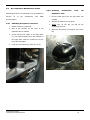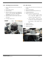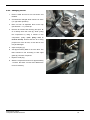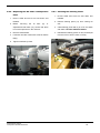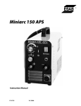
1
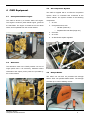
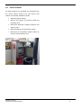
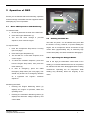
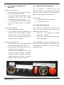
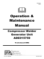
ADE018327 REV00 Operation & Maintenance Manual Compressor Welder Generator Unit ADE015759 Truck-based CWG Ph: +61 7 3863 5800 www.ade.net.au Table of Contents TABLE OF CONTENTS ....................................................1 1 GENERAL INFORMATION.................................1 2 SAFETY ...................................................................2 2.1 IMPORTANT SAFETY INFORMATION .......................2 2.2 SAFETY SIGNS & LABELS .......................................3 3 PRODUCT ID INFORMATION ...........................4 3.1 4 UNIT ID PLATE.......................................................4 CWG EQUIPMENT ...............................................5 4.1 CATERPILLAR/PERKINS ENGINE .............................5 4.2 ALTERNATOR .........................................................5 4.3 AIR COMPRESSOR SYSTEM .....................................5 4.4 KEMPI WELDER......................................................5 4.5 CONTROL CABINET ................................................6 5 OPERATION OF CWG .........................................7 5.1 BASIC CWG OPERATION AND MONITORING ..........7 5.2 UTILISING THE 240V AC ........................................7 5.3 AIR COMPRESSOR OPERATION AND MONITORING .8 5.4 COMPRESSOR OVERTEMPERATURE ........................8 5.5 GENERATOR HAS PRIORITY ...................................8 6 MAINTENANCE SECTION .................................9 6.1 GENERAL HAZARD INFORMATION..........................9 6.2 CWG MAINTENANCE SCHEDULE .........................10 6.3 CWG MAINTENANCE TASKS ...............................11 6.4 AIR COMPRESSOR MAINTENANCE SCHEDULE ......12 6.5 AIR COMPRESSOR MAINTENANCE TASKS ............13 6.6 CONSUMABLES FOR MAINTENANCE .....................17 7 LITERATURE REFERENCE MATERIALS ....18 7.1 OLYMPIAN GENERATOR DOCUMENTATION ..........18 7.2 AIR COMPRESSOR SYSTEM DOCUMENTATION .....18 Overview Compressor Welder Generator 1 1 General Information This guideline provides all the necessary information to operate and maintain Generator (CWG) Diversified Engineering. the unit Compressor supplied Use this by Welder Australian information in conjunction with the Olympian OEM information and mine site instructions where applicable. Refer to the Parts Manual for part information when sourcing replacement parts. The serial number of the CWG unit, found on the ID plate, may be required to determine appropriate parts. Refer to Section 3.1 in this manual for further information on the location of the ID plate. Whenever a question arises regarding the information contained within this manual please consult Australian Diversified Engineering Pty Ltd for the latest available information. Selected manuals may be found at www.ade.net.au containing the most up to date information for the product. General Information Compressor Welder Generator 1 2 Safety 2.1 Important Safety Information do not contain a safety alert or symbol such as Danger or Warning) are to indicate that an instruction must be carried out. The label will contain black text on a white Safety precautions and warnings may be listed in this background. Read and obey the information contained manual and applied to the product (supplied by on these labels. Australian Diversified Engineering) in the form of safety signs and labels. The NOTICE heading may be contained within this manual and is used to highlight or alert to certain Safety signs and labels may be positioned on specific aspects of the product. Commonly the NOTICE parts of the product to draw attention to objects and heading is used to highlight the weight of an object or situations affecting health and safety. If these hazard some other form of specific information applicable to warnings are not heeded, bodily injury or death may the task to be performed. occur to you or other persons. Australian Diversified Engineering cannot anticipate all The severity of the consequences of the hazard may possible hazards. For instance, some hazards may be be easily identified by the alert symbol at the top of the specific to your workplace or the equipment or tool you label. employ to complete the task. The DANGER alert symbol is used to warn of a Plan the job before proceeding. Planning before hazardous situation that is likely to be life threatening. commencement of the job will help identify possible Ensure you are aware of situations and locations on hazards in the job procedure which can be eliminated the product displaying this alert symbol. or controlled. Be aware of unintended movement when assembling and disassembling components and ensure machines are isolated in accordance with workplace and supplier The WARNING alert symbol is used to warn of a instructions when performing maintenance. hazardous situation that is not likely to be life threatening. Ensure you are aware of situations and locations on the product displaying this alert symbol. Ensure items are installed properly and are not damaged during the installation procedure or during operation of the machine. If damaged or installed incorrectly the product may not operate and perform as intended and may be made unsafe as a result. Ensure The wording given underneath the DANGER or all items are repaired or replaced and care is taken WARNING alert symbol will warn of the hazard, the when installing items on the machine. consequences of the hazard followed by information on how to prevent the hazardous situation from occurring. Operate and maintain the machine in accordance with procedures Some signs placed on the product or machine (which specified by the original equipment manufacturer and information contained within this manual. Safety Section Compressor Welder Generator 2 2.2 Safety Signs & Labels There are several specific safety signs specific to the service vehicle. Their exact location and description of the hazard are reviewed in this section. Make sure that you can read all safety signs. You must replace a label if it is damaged, missing or cannot be read. If a label is on a part that is replaced, make sure a new label is installed on the replaced part. Contact Australian Diversified Engineering for replacement labels. This sign is located on the top of the electrical cabinet Safety Section Compressor Welder Generator 3 3 Product ID Information 3.1 Unit ID Plate An ID plate has been fitted to each machine to indicate information such as the date of manufacture and serial number. Refer to the fitted ID plate for further information. ID plate affixed near the oil separator tank Product Identification Section Compressor Welder Generator 4 4 CWG Equipment 4.3 Air Compressor System The CWG is equiped with a 40 CFM air compressor 4.1 Caterpillar/Perkins Engine system, which is controlled and monitored at the control cabinet. The system consists of the following The CWG is driven by a Perkins 403D-11G engine. components: The engine is a inline 3 piston diesel engine, governed 1. Air end at 1500 RPM. The engine is fueled the truck’s diesel 2. Oil separator tank, with: tanks, and is operated from the control cabinet. o Oil filter (small can) o Separator/De-oiler filter (large can) 3. Oil cooler 4. Air cooler 5. Air filter/water sepator regulator 4 2 3 1 4.2 Alternator The alternator used in the CWG provides 7.5 kVA of 5 single phase 240 V AC electricity. Alternator status information and output power points are provided by 4.4 Kempi Welder the control cabinet. The CWG unit will also be provided with Kemppi Miniarc EVO 150 portable MMA welder. The Kemppi provides up to 140A of welding current. Operation Section Compressor Welder Generator 5 4.5 Control Cabinet All CWG functions are controlled and monitored from the control cabinet, fitted in the rear driver’s side cabinet. Functionality available includes: Start and stop the engine Monitor the engine’s oil pressure, RPM and operating hours. Monitor the alternator’s voltage, frequency and output current. Start and stop the air compressor system. Monitor the air compressor systems status, air pressure and operating hours. Operation Section Compressor Welder Generator 6 5 Operation of CWG 1 2 Ensure you are familiar with the functionality, operation and all warnings associated with this equipment before attempting any form of operation. 5.1 Basic CWG Operation and Monitoring To start the CWG: 1. Check all personnel are clear of the CWG unit. 5 4 3 2. Press the Engine Start button (1). 3. The unit will move through a pre-start 5.2 Utilising the 240V AC sequence, then crank the engine. The 240V AC power can be utilised at any time that the CWG is running. However, to prevent stalling the To stop the CWG: 1. Push the Compressor Stop switch, if running engine, the air compressor will be shut down at high current draw (approximately 6A). At extremely high (see over page) current draw (20A), the clutch will also be disengaged. 2. Press the Engine Stop button (2). 3. The unit will run a cool down sequence, then cut the engine. 4. To cancel the cooldown sequence, press and hold the Engine Stop button, then press the return button (3). 5.2.1 Operating the Kemppi Welder Due to the high yet intermittant current draw of arc welding, it is recommended that the the air compressor be switched off and clutch disengaged before welding 5. In case of emergency, press the CWG commences. Operating the air compressor while Emergency Stop button (see over page). This welding may adversely affect the longevity of the should only be done in an emergency situation clutch. as it bypasses the engine’s cooldown sequence. Monitoring the CWG: Pressing the Engine Monitoring button (4) displays the engine oil pressure, RPM and operating hours. Pressing the Alternator Monitoring button (5) displays the alternator voltage, frequency and current draw. Operation Section Compressor Welder Generator 7 5.3 Air Compressor Operation and Monitoring To start the air compressor: 5.4 Compressor Overtemperature The air compressor is protected by an over temperature switch. If the compressor outlet reaches 1. Check all personnel are clear of the CWG unit. 105 °C the switch will shut down the compressor and 2. Press the Compressor On button. prevent it from restarting until it cools to 90 °C. 3. The clutch will engage immediately, and the compressor load valve will operate Possible causes: approximately 30 seconds afterward. 1. Cooler filter element may be blocked. 4. The compressor load valve will be modulated 2. Low compressor oil level. to keep air pressure within an acceptable range. To stop the air compressor: 5.5 Generator Has Priority If the generator and compressor are running at the 1. Push the Compressor Off switch. same 2. The compressor will unload immediately, but undergoing a large current draw: the clutch will remain engaged for several minutes in order to cool the compressor oil. The CWG must left running during this time (cooldown cycle is acceptable). Monitoring the air compressor: time, the generator takes priority Above 6A – The compressor is unloaded, clutch remains engaged. Above 20A – The compressor is unloaded, clutch is disengaged. When underaking tasks with intermittant but high The Compressor Air Pressure gauge displays current draw, such as welding, it is recommended that the air pressure available in the reservoir. the compressor is switched off to prevent excessive The Compressor Hours gauge tracks the air cycling of the clutch. compressor’s hours of operation. when The compressor’s filter/regulator must be set at 110 PSI or higher, otherwise compressor activation will cause the engine to stall. If lower pressure regulation is required, a separate regulator must be used at the air outlets. Operation Section Compressor Welder Generator 8 6 Maintenance Section 6.1.2 Crushing & Cutting Prevention Disconnection of hoses and removal of supporting pins and bolts of the service vehicle may result in unintended machine movement and/or release of stored energy. Personal injury or death may result. Before disassembly of any components of the service vehicle ensure that stored energy has been relieved and components are chocked/blocked to prevent unintended movement. Unintended machine movement may result in personal injury or death. Before performing maintenance on this machine ensure it has been isolated in accordance with mine site and manufacturer procedures and a Do Not Start Tag has been applied in the appropriate location on the machine. NOTICE You must read and understand the warnings and instructions contained in the Safety Section of this manual, before performing any maintenance procedures. 6.1 General Hazard Information Support equipment and attachments properly when working beneath them. Never attempt adjustments while the machine is moving or the engine is running unless otherwise specified. Stay clear of all rotating and moving parts. Perform all maintenance unless otherwise specified as follows: The vehicle parked on level ground. The engine and CWG stopped. The start switch key off and the key removed. All disconnect switches locked out and a Do Not Start Tag applied. Pressure relieved in the system which is to be serviced. All other external energy sources disconnected from the machine. 6.1.1 Oils & Coolant Oils and coolant may be hot and under pressure. Before serving components on this vehicle ensure all pressure is relieved in the system and fluids have been allowed sufficient time to cool. Maintenance Section Compressor Welder Generator 9 6.2 CWG Maintenance Schedule 6.2.5 Every 500 Hours (or 1 year) This schedule is based on the CWG operation Fuel system filter – Replace hours, Engine air cleaner Element – Clean/Replace Engine oil and filter – Change Hose and clamps – Inspect/Replace Radiator - Clean which are displayed on the Engine Monitoring screen of the CWG control panel. Note – This maintenance schedule is indicative only. Please refer to Section 9 of the Olympian Operator and Maintenance Instruction Manual, and page 60 of the Perkins Operation and 6.2.6 Every 1000 Hours Maintenance Manual for detailed requirements and instructions. 6.2.1 When Required Belts – Replace Engine valve lash – Inspect/Adjust Gearbox oil - Change Engine – Clean Engine air cleaner element – Clean/Replace Fuel system – Prime Alternator – Inspect Severe service application – Check Engine crankcase breather – Replace Engine mounts – Inspect Starting motor – Inspect 6.2.2 Daily 6.2.7 Every 2000 Hours Engine oil level – Check Engine coolant level – Check Driven equipment – Check Engine air cleaner service indicator – Inspect Engine air precleaner – Check/Clean Fuel injector – Test/Change Fuel system primary filter/water separator – Water pump – Inspect 6.2.8 Every 3000 Hours Cooling system water temperature regulator – Replace Drain Walk-around inspection 6.2.3 First 100 Hours ONLY 6.2.9 Every 6000 Hours (or 3 years) Cooling system coolant – Change (if Commercial Heavy-Duty) Gearbox oil – Change/Flush 6.2.10 Every 12000 Hours (or 6 years) 6.2.4 Every 250 Hours (or weekly) CWG control system handling of electrical Cooling system coolant – Change (if Extended Life Coolant) faults by simulating faults – Test Exhaust connections – Check/Tighten Electrical connections – Check/Tighten Belts – Inspect/Adjust Gearbox oil level - Check Maintenance Section Compressor Welder Generator 10 6.3 CWG Maintenance Tasks Maintenance tasks not described here are detailed in Section 9 of the Olympian Operator and Maintenance Instruction Manual, and page 60 of the Perkins Operation and Maintenance Manual. 1 6.3.1 Checking the Gearbox Oil Level 1. Remove oil level inspection plug (1). 2. Check oil level via the oil level inspection hole. Oil level should meet the inspection hole, or be just under. 3. Replace the oil level inspection plug.. 2 6.3.2 Changing the Gearbox Oil 1. Run the CWG up to operating temperature. 2. Shut down then isolate CWG and truck. 3. Undo oil drain cap (2). 4. Allow gearbox oil to drain into a container (a funnel may be required). 5. Replace oil drain cap. 6. Remove oil level inspection plug (1). 7. Remove breather (3) from the oil expansion tank, and pour approximately 350mL of new 3 gearbox oil into the tank. 8. Allow oil to drain into the gearbox. 9. Check oil level via the oil level inspection hole. Oil level should be filled to the level of the inspection hole. Fill more if required. 10. Replace the oil level inspection plug and the breather. Maintenance Section Compressor Welder Generator 11 6.4 Air Compressor Maintenance Schedule This schedule is based on the air compressor operation hours, which are displayed on the Compressor Hours gauge on the CWG control cabinet. Note – This maintenance schedule has been adapted from Section 15 of the Compressor Unit OEM documentation, which should be referred to for further instructions. 6.4.1 Daily Walk-around inspection Check compressor oil level 6.4.2 Every 25 Hours Drain condensate from oil separator tank Clean cooler filter panel 6.4.3 Every 250 Hours Clean air suction filter Check belt tension 6.4.4 Every 1000 Hours Change the oil Change the oil filter Change the air suction filter 6.4.5 Every 2000 Hours Clean the finned surface of the oil and air coolers Change the oil separator/de-oiler filter Maintenance Section Compressor Welder Generator 12 6.5 Air Compressor Maintenance Tasks 6.5.2 Draining Maintenance tasks not described here are detailed in Section 15 of the Compressor Unit OEM documentation. Condensate from Separator Tank 1. Ensure CWG and truck are shut down and isolated. 6.5.1 Checking Compressor Oil Level 1. Switch off the air compressor. 2. Wait for the machine to cool down. 3. Slowly turn on the tap (2) and let the condensate flow out. 2. Wait a few minutes for the foam in the separator tank to subside. 4. When the first traces of oil appear, turn off the tap. 3. Check fluid level is visible on the sight glass (1). The minimum fluid level is at the bottom of the sight glass, while the maximum is at the top of the sight glass. 4. If the oil level is below the minimum, top up. 2 1 Maintenance Section Compressor Welder Generator Oil 13 6.5.3 Cleaning the Air Suction Filter 1. Ensure CWG and truck are shut down and 6.5.4 Belt Tension 1. Ensure CWG and truck are shut down and isolated. isolated. 2. Remove filter cover (2). 2. Remove the belt guard. 3. Remove the filter. 3. Slacken the air end screws by half a turn (3). 4. Clean the filter with a jet of air, working from 4. Loosen the locknut (4). inside to outside. DO NOT USE WATER OR 5. Adjust the tension by turning screw (5). SOLVENTS. Alternatively, fit a new filter. a. New belt - deflection should be 6mm 5. Clean the disk on which the filter rests with a for clean cloth. a 4kg force applied at the centreline, at right angles to the belt. 6. Fit the filter and the cover. b. 100 hrs Operation - deflection should be 2mm for a 2.5kg force applied at the centreline, at right angles to the belt. 2 6. Tighten the locknut. 7. Tighten air end screws. 8. Replace belt guard. 5 4 3 Maintenance Section Compressor Welder Generator 14 6.5.5 Changing the Oil 1. Ensure CWG and truck are shut down and 6 isolated. 2. Oil should be changed while machine is warm (i.e. right after operation) 3. Drain oil from oil separator tank via the tap (see Section 1.1.1). Close tap. 4. Remove air suction filter housing and pour 1L of oil slowly down the neck (6), while cycling the compressor by using a ratchet on the compressor pulley (note pulley bolt is reverse thread). Ensure that the oil is being pumped out of the air end, or else the air end 7 may be damaged. 5. Open oil fill plug (7). 6. Add approximately 2.5L of oil to the tank. The tanks should be full according to tank sight glass (8). Fill more if required. 7. Replace oil fill plug. 8 8. Start the compressor and run for approximately 1 minute. Re-check oil level and add/remove more if necessary. Maintenance Section Compressor Welder Generator 15 6.5.6 Replacing the Oil Filter and Separator Filter 6.5.7 Cleaning the Filtering Panel 1. Ensure CWG and truck are shut down and 1. Ensure CWG and truck are shut down and isolated. 2. Before isolated. 2. Remove filtering panel (11) from cowling via removing the oil filter (9), or separator/de-oiler filter (10), ensure that there slot. 3. Clean filtering panel with a jet of air and wash with water. DO NOT USE SOLVENTS. is no stored pressure in the reservoir. 3. Remove desired filter. 4. Reinstall the filtering panel via slot, and adjust 4. Lubricate new filter seals with a little oil before from the front to ensure it sits correctly. fitting. 5. Tighten new filter by hand. 10 9 Maintenance Section Compressor Welder Generator 11 16 6.6 Consumables for Maintenance The following consumables required by the CWG are available for order from ADE. Part Part Number Gearbox oil ADE018575 Air compressor oil ADE018547 Air compressor oil filter ADE018548 Air compressor oil ADE018549 separator filter Pre-cooler filtering panel ADE018207 Belt ADE017854 Maintenance Section Compressor Welder Generator 17 7 Literature Materials 7.1 Reference Olympian Generator Documentation The Olympian generator documentation has been provided with the CWG. 7.2 Air Compressor System Documentation The CSA 10 air compressor documentation has been provided with the CWG. Reference Information Compressor Welder Generator 18