1
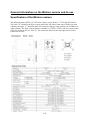
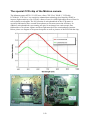
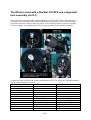
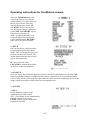
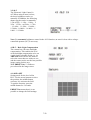
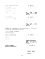
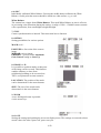
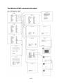
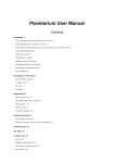
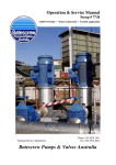
Langenbrettach/Germany, February 8th 2004
Matthias Bopp
Controlling the Mintron Camera remotely
Table of content
Table of content.......................................................................................................................... 1
General information on the Mintron camera and its use............................................................ 2
Specification of the Mintron camera ...................................................................................... 2
The special CCD chip of the Mintron camera........................................................................ 3
The Mintron used with a NexStar N11GPS and a Hyperstar lens assembly (at f/2.1) .......... 4
Changing the green LED of the Mintron video camera to a dimmed red LED ..................... 5
Operating instructions for the Mintron camera ...................................................................... 6
The Mintron OSD command structure................................................................................. 10
Adding a RS232 interface to the Mintron camera.................................................................... 11
Concept of the RS232 interface ........................................................................................... 11
Remote connector for the RS232 interface .......................................................................... 11
Schematic of the RS232 interface module ........................................................................... 11
Layout and assembly plan of the RS232 interface module .................................................. 12
How to assemble the module into the Mintron camera........................................................ 13
Schematic of an extended the RS232 module ...................................................................... 15
Simple RS232 cable for the Mintron video camera ............................................................. 16
Advanced cabling for the Mintron video camera................................................................. 16
Software to control the Mintron camera remotely ................................................................... 17
Interface protocol ................................................................................................................. 17
List of commands for use with the Mintron camera ............................................................ 17
Using the Software “Hyper Terminal” from Windows........................................................ 18
Using the Software “StellaCam TM Control”........................................................................ 21
Using the Software “StellaCam TM Buttons” ....................................................................... 21
Using the Software “Radio Remote Control” ...................................................................... 22
Using a radio link to control the Mintron camera ................................................................ 22
Source code for the ATMEL controller ............................................................................... 22
Conclusion and acknowledgement........................................................................................... 22
1/22
General information on the Mintron camera and its use
Specification of the Mintron camera
The Mintron camera MTV-12V1-EX uses a Sony exview HAD ½” CCD-chip ICX249AL.
The letter “E” identifies the EIA version used in the US with a frame rate of 60Hz (see mid
column), the letter “C” identifies the PAL version for Europe using a frame rate of 50Hz (see
right column). The PAL version features a number of 752(H) x 582(V) effective pixels with a
pixel size of 8.6um (H) x 8.3um (V). The connector shown on the top right can be used to
control an Iris lens.
2/22
The special CCD chip of the Mintron camera
The Mintron camera MTV-12V1-EX uses a Sony "EX-View" HAD ½” CCD-chip
ICX249AL. "EX-View" is a sensitivity-enhancement technology developed by SONY to
improve light sensitivity of its CCD by a factor of two for visible light and a factor of four for
near-infrared wavelengths. The P/N junction of each photodiode in the CCD matrix is
specially fabricated to have a much better photon-to-electron conversion efficiency. In
addition, each photodiode (representing one pixel in an image) has a microscopic lens
fabricated over it to better capture and focus light onto the active semiconductor junction.
Below please see diagram of its spectral response as well as pictures of the PCB with the chip.
3/22
The Mintron used with a NexStar N11GPS and a Hyperstar
lens assembly (at f/2.1)
One of the most amazing results using the Mintron at the N11GPS can be achieved when
using this camera in conjunction with the Hyperstar lens assembly. This wide-field setup is
especially suited for a remote observing setup. You can find an article on how to build the
necessary adapter on my homepage. Here are some pictures of the complete assembly:
Comparison table of N8GPS & Fastar lens assembly & ST237A versus N11GPS & Hyperstar
lens assembly & Mintron camera:
Telescope
N8GPS
N11GPS
Telescope aperture diameter 200mm
279mm
Telescope focal ratio
f/10
f/10
Telescope focal distance
2000mm
2790mm
Lens assembly
Fastar (Celestron)
Hyperstar (Starizona)
Resulting focal ratio
f/1.9
f/1.8
Resulting focal distance
390mm
500mm
Camera
ST237A (SBIG)
MTV-12V1-EX (Mintron)
Pixel size
7.4 x 7.4 um (H,V)
8.6 x 8.3 um (H,V)
Array size
657 x 495 pixels (H,V)
752 x 582 pixels (H,V)
Chip size
4.9 x 3.7 mm (H,V)
6.47 x 4.83 mm (H,V)
FOV
42.8 x 32.2 arcmin (H,V)
44.2 x 32.9 arcmin (H,V)
Image scale
3.91 arcsec/pixel
3.45 arcsec/pixel
4/22
Changing the green LED of the Mintron video camera to a
dimmed red LED
I really like the Mintron video camera for deep-sky observations in conjunction with my
N11GPS and the Hyperstar lens assembly very much. However I found the very bright green
LED on the back, indicating that the camera is powered and thus active, very annoying. Thus
I replaced it with a dimmed red LED and thus:
a) the dark adoption of the eye will no longer be disturbed
b) the likelihood, that the pictures are disturbed by stray light coming from the bright LED is
reduced
c) power consumption is reduced by approx. 150 mW. This corresponds to approximately
7% of the whole camera. Thus also the heat generated in the camera and creating warm
pixels at the CCD is reduced.
There are only two components to be replaced:
1) the green LED “D1” is replaced by a low current 3mm red LED. Don’t worry; if you mix
up the two leads (Anode and Cathode) of the LED, nothing gets damaged. You just have
to solder it in once more correctly.
2) the 820 Ohms resistor “R1” is replaced by a 100kOhm resistor
Here is the small schematic change. On the left you see the old, on the right the new changed
schematic. It may be a good idea to test the combination of your LED and resistor with
respect to the achieved brightness before you solder them onto the board because some LEDs
may not turn on with 100 uA of current.
And here are two pictures to find the Resistor and the LED in the camera.
On the left you see the resistor “R1”
On the right you see the red LED “D1”
5/22
Operating instructions for the Mintron camera
There are 5 push buttons on the
back of the camera. Pressing the
middle button (2 seconds) activates
the on-screen menu. Select the
individual functions via the UP
and DOWN arrows. De-activate
any function or change a parameter
via the LEFT and RIGHT arrows.
Dots after a selection (e.g.
AGC…) indicate that there is an
extended menu; this is activated
via the middle button. RETURN
takes one to the previous menu.
1. TITLE
One can insert text, which can later
be superimposed onto the camera
image. One can change the signs and
position via the arrow buttons. The
middle button transfers the selected
sign to the bottom line.
SP: space forward / back
LOCATION: confirm the position
of the text via the arrow buttons
2. SENSE UP
Here one selects the maximum integration time for the Star-Light function. In the Star-Light
function individual images are added into the camera‘s memory, up to a selected maximum
value (128X), thereby increasing the light sensitivity. Because of the technology involved, the
image refresh rate reduces with an increase in integration time.
3. ALC/ELC
3.1 ELC
In this mode the camera works
with Electronic Light Control
(ELC). The shutter works automatically.
No auto iris lens is necessary.
LEVEL enables one to set the basic
brightness manually.
6/22
3.2 ALC
The Electronic Light Control is
off. When using an auto iris lens,
the basic brightness can be set
manually. In addition, the following
shutter speeds can be set manually:
1/50s (OFF) – 1/120s – 1/180s – 1/
250s – 1/350s – m1/500s – 1/750s
– 1/1.000s – 1/1.500s – 1/2.000s –
1/3.000s –1/4.000s – 1/6.000s – 1/
8.000 – 1/12.000s
Note: For automatic brightness control in the ALC function, an auto iris lens with a voltagecontrolled aperture (DC) is necessary.
4. BLC - Back Light Compensation
The camera has a 48-zone backlight
compensation. This enables the level
of the backlight compensation to be set
via 48 freely-selectable fields; i.e. via
AREA SET one can use the fields to
select the zones that one wishes to see,
and the camera works out the best possible
image setting for this area.
With PRESET On, 12 fields are
pre-selected in the image centre.
4.1 AREA SET
Setting mode for the level of the
BLC. Use the arrow buttons to select
the position; the middle button
activates / de-activates the field.
To quit the function, press the
middle button for 2 seconds.
PRESET On means that it is not
possible to change the field settings.
7/22
5. AGC - Automatic Gain Control
5.1 AGC OFF
Automatic Gain Control is off.
5.2 AGC ON
Automatic Gain Control is on.
LEVEL enables one to select the
maximum value of 0-18dB.
5.3 AGC MANU
Automatic Gain Control of
0 - 18dB can be set via LEVEL.
6. W/B SELECT – White Balance (no function on S/W types 13V0, 13V1 and 12V1)
The camera has 3 possible white-balance functions.
6.1 ATW - Automatic White Balance
Automatic white balance.
6.2 MANU... PRESET OFF
Manual white-balance setting.
RED : red
BLUE : blue
6.3 MANU... PRESET
Manual setting of preset colour
temperatures 3200K or 5600K.
8/22
6.4 AWC
Individually calibrated White Balance. Pressing the middle button calibrates the White
Balance. At this point the camera should be aimed at a white surface, e.g. a wall.
White Balance
The camera has a single-frame White-Balance. This rapid White Balance in 6ms is effective
in preventing color distortions during the setting. A range of 2200 – 15000oK ensures natural
color reproduction, from candlelight to bright daylight.
7. SYNC
Camera synchronization is internal. This menu item has no function.
8. OPTION
Setting possibilities for various options.
MASK see 8.1
POSI/NEGA : Inversion of the camera
image
MIRROR : mirror image
PRIORITY : priority of the Automatic
Gain Control setting or Sense Up
8.1 MASK A...D
It is possible to position masks so that parts
of the image can be covered. This function
enables windows or doors from
neighboring buildings to be screened out.
This is a requirement in some countries.
LOCATION: The position of the mask
can be determined via the arrow buttons.
SIZE: The size of the mask can be
determined via the arrow buttons.
9. ZOOM
A two-fold digital zoom is possible
via the arrow keys.
10. SAVE
Storing the settings and quitting the on-screen-display menu. The settings are restored to these
stored values also after a power off, power on cycle.
9/22
The Mintron OSD command structure
10/22
Adding a RS232 interface to the Mintron camera
Concept of the RS232 interface
The basic concept of the RS232 control interface is to mimic the buttons remotely.
Besides this there are 3 additional general purpose control outputs P1.0 to P1.2 available.
Remote connector for the RS232 interface
I replaced the connector on the rear of the Mintron, which is normally used as an S-Video
output, by a 6 pin Mini.-DIN connector and use it also for the remote control operation. The
S-Video output is not really necessary at a black/white camera because the same signal is
available at the BNC connector. However I still use one of the pins as a video output because
this allows me to connect all signals, including the power supply of the Mintron, with this
single connector. This allows a quick and easy setup and is especially nice when using it with
the Hyperstar lens assembly in front of the telescope (see also section “The Mintron used with
a NexStar N11GPS and a Hyperstar lens assembly (at f/2.1)”).
1 = GND
2 = Composite Video Output
3 = TXD (RS232 input, +/- 12V levels)
4 = Switch output P1.0 (e.g. video switch)
5 = GND
6 = 12V DC input/output
Schematic of the RS232 interface module
11/22
Layout and assembly plan of the RS232 interface module
The first 2 pictures show the layout of the single sided PCB as well as the assembly plan. The
layout data will be posted on my webpage as a binary file for easy reproduction.
The picture below shows how the connectors are wired to the 5 buttons on the rear panel of
the Mintron camera (K4) and to the RS232 interface (K3). Connector K5 is wired to Pins 1
and 6 of K3 and will be plugged into the free jack of the horizontal main PCB in the Mintron
camera. It supplies the necessary 3.3V power supply to the new RS232 interface module.
12/22
How to assemble the module into the Mintron camera
Rear view of the Mintron camera
This shows the new remote
control connector from the rear
Here the S-Video connector
is already replaced by the new
6 pin remote control connector
Side view of the Mintron camera while
open. No changes on the shown PCB
More detailed view of the board
Here on the very right the wires
connecting the new PCB (shown
later) to the buttons are shown
13/22
New PCB with ATMEL controller assembled
The white circles identify the pins of
the buttons which are tied to ground.
The black circles identify the signal
pins, which are pulled to ground while
the respective button is pressed. The
control outputs at Connector K4 of the
new PCB with the ATMEL controller
are connected by wires one of the
black marked points of each button.
Wires connecting the new PCB to
the buttons (explanation see right)
Detail view how PCB is fixed
to the existing frame
Detailed view of the new controller board with the
ATMEL controller
14/22
Schematic of an extended the RS232 module
This extended module provides a open collector output signal which can be tied to an external
voltage which can exceed the supply voltage of the AT89C4051 controller.
Port pins P1.2 to P1.7 provide internal pull-up resistors tied to the supply voltage of the IC
(AT89C4051). P1.0 and P1.1 require external pull-ups (you can see the 2k7Ohm pull up resistors). The hand written additional parts are needed to use the general purpose I/O-ports P1.0
and P1.1 to control additional devices. They are additional parts which are not foreseen on the
PCB. I use these ports to control a video switch and I intend to use the second one to switch a
cooling fan for the Mintron video camera on and off. The npn-transistor (I used a BC548) inverts the signal and acts as an open collector output. It can for instance initiate an external relay. The 100 Ohm series resistor is used to protect the transistor from over current, the diode
(e.g. a 1N4148) protects the transistor from negative voltage transients generated when
switching inductive loads (e.g. a relay-coil). The 1nF capacitor blocks noise and interferences.
15/22
Simple RS232 cable for the Mintron video camera
The easiest way to connect the Mintron
video camera to the RS232 port of your PC
is to use the following cable. You only
need to connect 2 wires plus the shielding
of the cable as shown in the diagram. You
do not need to connect the other Pins
unless you need them.
Advanced cabling for the Mintron video camera
This diagram shows an
advanced wiring for the
Mintron camera like I use it
presently. The 6 pin
connector at the rear panel of
the Mintron connects the
Mintron to the RS232 port of
the PC, supplies the 12V DC
power to the Mintron,
delivers the video output
signal to a video switch
which is controlled by a
signal also routed via this
connector.
16/22
Software to control the Mintron camera remotely
Interface protocol
The RS232 parameters to be used are: 9600bd, 8 bit, no parity, 1 start-bit, 1 stop-bit, LSB
first. The interface is only unidirectional (only commands are sent to the camera). No
information is sent from the camera back to the PC. Therefore only the TXD-line is used
(besides Ground) as was explained in the previous section on how to build the cable.
List of commands for use with the Mintron camera
Connect the camera to a free COM-port of your PC by using the serial adaptor cable as
described before. The control protocol of the interface is very simple. If the interface receives
a character from the PC as listed below, it will activate the button according to the received
character. Due the simple protocol there is no special control software needed, and you may
also use other devices like a PDA to control the camera. Furthermore you are not dependent to
an operating system like Microsoft Windows because you just need any program which can
send serial characters to the camera.
Example: to activate the OSD send the command “E”. Then you can navigate through the
menus by up-commands (send command “U” or “8” to move up one line) and downcommands (send command “D” or “2” to move down one line).
ASCII
Cmd.
a
D
E
g
L
p
R
U
V
v
X
x
Y
y
z
2
4
5
6
8
ASCII
Dec.#
97
68
69
103
76
112
82
85
86
118
88
120
89
121
122
50
52
53
54
56
Mintron
12V1C-EX
Shortcut to submenu „ALC/ELC“
Down (also “2“)
Menu/Enter (also “5“)
Shortcut to submenu „Gain“
Left (also “4“)
Preset ( = Reset to default values)
Right (also ”6”)
Up (also ”8”)
P1.2 / PIN14 ON (0V)
P1.2 / PIN14 OFF (3V)
P1.1 / PIN13 ON (0V) -> I use it to switch cooling fan on
P1.1 / PIN13 OFF (3V) -> I use it to switch cooling fan off
P1.0 / PIN12 ON (0V) -> I use it to switch to video source 1
P1.0 / PIN12 OFF (3V) -> I use it to switch to video source 2
Shortcut to submenu „Zoom“
Down (also “D“)
Left (also “L“)
Menu/Enter (also “E“)
Right (also ”R”)
Up (also “U“)
Please note: if you want to use the shortcut-commands OSD (on-screen-display) must be off.
17/22
Using the Software “Hyper Terminal” from Windows
Windows Hyper Terminal is a standard tool of Windows 98/NT/2000. In principle you may
also use any other terminal program which is able to send characters via the COM port to the
camera. In order to setup Windows Hyper Terminal to control the camera, please follow the
instructions below:
1. Start Windows Hyper Terminal.
2. Setup a new connection and choose a name for it like MTV-12V1.
18/22
3. Choose ‘connect using COM1’. If you are using another COM port please chose the
number of the port where the camera is connected.
4. Setup the serial parameters as shown in the image.
After Hyper Terminal starts up you may minimize the window.
19/22
If the Hyper Terminal window is active, and the camera is well connected to the COM port,
you are able to control the camera by using the number block of your PC keyboard just like
the buttons on the back of the camera. Please see the table of commands in the previous
chapter.
If you close Hyper Terminal click ‘YES - Save session’. To restart Hyper Terminal with this
setup you will only need to click on the icon MTV-12V1.
20/22
Using the Software “StellaCam TM Control”
It looks like this controller uses the same command set and interface protocol as the Stellacam
Camera. Therefore the Stellacam TM Control software may be used. Of course I cannot
guarantee that this holds true especially for future releases of the Stellacam TM software.
Please check with ADIRONDACK VIDEO ASTRONOMY or Astrovid (the company which sells
the StellaCam TM Cameras) whether it is legal to operate their software which can be
downloaded from their webpage without using their own hardware. Some more information
can be found on the following page: http://www.astrovid.com/astrovid__stellacam.htm
TM
Using the Software “StellaCam TM Buttons”
Also this simpler program for the StellaCam TM camera should work with this Mintron camera
modification. Please check with ADIRONDACK VIDEO ASTRONOMY or Astrovid (the company
which sells the StellaCam TM Cameras) whether it is legal to operate their software without
using their own hardware.
21/22
Using the Software “Radio Remote Control”
This is a flexible shell from which you can call programs to control your camera or initiate
commands directly. There are only 2 files needed: RaRemCtrl.exe and RaRemCtrl.ini. The
.ini file is a plain ASCII file which allows to configure the buttons shown in the example
above. This program can be downloaded from my webpage free of charge.
Using a radio link to control the Mintron camera
Of course the RS232 cable can also be replaced by a wireless link. Please visit my webpage
on how to use DECT based radio links to replace the wires both to the NexStar telescope and
also to this camera. Actually I use the same link to control both, my Casio digital camera and
my Mintron video camera.
Source code for the ATMEL controller
The source code “mtv232b.c” and the hex-file “mtv232b.ihx” to program the ATMEL
controller as well as a Gerber file for the PCB “interface.T3001“ is posted on my website.
Please download the file “mtv232 code and layout.zip”. It contains these files.
Conclusion and acknowledgement
I hope you also have fun with this nice camera. Please check my webpage regularly for
updates, additional information and modifications for the Mintron camera. Any questions and
hints on further improvements are always very welcome. All information contained here are
provided free of charge. Building such a module and / or operating it is at your own risk !
I want to thank Mr. Guenter Lechner for the development of this interface and for his
permission to publish all these information here on my website. Please visit his website at
http://www.lechner-cctv.de
Best regards
Matthias
Email: [email protected]
Homepage: www.dd1us.de
22/22