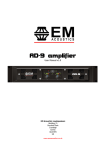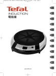
1
MC
S Series
Signature Reference Power Amplifiers
S1400/S800
Operating Instructions
MC
www.mc2-audio.co.uk
Tel. +44 (0)1404 44633 Fax. +44(0)1404 44660
2
MC AUDIO | Units 6-8 Kingsgate | Heathpark Industrial Estate
Honiton | Devon | England | EX14 1YG
Page 2
S Series – S1400/800 Operating Instructions
S Series – S1400/800 Operating Instructions
Page 3
CONTENTS
DECLARATION OF CONFORMITY ........................................................................ 4
THANKS............................................................................................................... 5
INTRODUCTION................................................................................................... 5
IMPORTANT SAFETY INSTRUCTIONS ................................................................ 6
INSTRUCTIONS DE SECURITE IMPORTANTES ...................................................7
Installing Your Amplifier: Electrical Considerations......................................... 8
Installing Your Amplifier: Mechanical Considerations...................................... 9
Connecting To Your Amplifier: Inputs and Link Outs ....................................... 10
Connecting To Your Amplifier: Speaker Outputs...............................................11
Connecting To Your Amplifier: Bridged (Mono) Operation................................11
Operating Your Amplifier: Front Panel Controls and Indicators...................... 12
Operating Your Amplifier: Notes and Switching On ......................................... 13
Operating Your Amplifier: Rear Panel Sockets and Switches ......................... 14
Looking After Your Amplifier: Maintenance ..................................................... 15
Looking After Your Amplifier: Warranty ........................................................... 15
Performance Of Your Amplifier: Specifications ............................................... 16
S Series – S1400/800 Operating Instructions
Page 4
DECLARATION OF CONFORMITY
We, the manufacturer:
MC2 Audio,
Units 6-8 Kingsgate
Heathpark Industrial Estate
Honiton, Devon
England
EX14 1YG
acknowledge our responsibility that the following products:
Kind of equipment:
Commodity Code:
Type Designation:
Audio amplifier
8518408990
T500, T1000, T1500, T2000, T3500, T4-250
Ti500, Ti1000, Ti1500, Ti2000, Ti3500, Ti4-250
E15, E25, E45, E90, E100, E475
S800, S1400
and all OEM variants of these models
are manufactured:
in accordance with EMC Directive 2004/108/EC,
in compliance with the following norm(s) or document(s):
Technical Regulations: EN55103-1:1996, EN55103-2:1996
and
in accordance with the Low Voltage Directive 2006/95/EC,
in compliance with the following norm(s) or document(s):
Technical Regulations: EN/IEC60065:2002 7th Edition
Signed:
……………………………………………………………………
Name:
Position:
Date:
Alex Cooper
Research and Development Manager
January 2012
S Series – S1400/800 Operating Instructions
Page 5
THANKS
Thank you for choosing an S Series amplifier for your application.
Please spend a little time reading through this manual, so that you obtain the best possible
performance from the unit and become familiar with its operating requirements.
All MC2 products are carefully designed and engineered for cutting-edge performance and
world-class reliability. If you would like further information about this or any other MC2
product, please contact us.
We wish you many years of service from this amplifier and look forward to hearing from you
in the near future.
INTRODUCTION
Designed for use in the best studio monitoring environment, but equally at home in any
application where transparency and “no compromise“ performance are the focus,
the S Series amplifiers deliver the sound quality and reliability expected from MC2.
These amplifiers utilise the best complimentary AB bipolar output stages, combined
with the unique MC2 current driven floating drive stage along with analogue level controls for
minimal signal degradation.
Sophisticated “side-chain” limiters prevent distortion and speaker damage, but are out-ofcircuit until the onset of clipping so do not compromise the signal path under normal working
conditions. A bespoke high fidelity shielded toroidal power supply combined with intelligent
low noise fan control provide optimum conditions for the output stages, ensuring the only
thing you will ever hear is your sound.
Critical parts have been selected through a series of listening tests for optimum sonic
performance and approved by some of the most well respected personnel in the industry.
The amplifiers of course include full DC, thermal and short circuit protection to ensure
trouble-free service.
Page 6
S Series – S1400/800 Operating Instructions
IMPORTANT SAFETY INSTRUCTIONS
CAUTION: RISK OF ELECTRIC SHOCK.
DO NOT OPEN
The lightning flash with arrowhead
symbol within an equilateral triangle is
intended to alert the user to the presence
if uninsulated “dangerous voltage” within
the product’s enclosure that may be of
sufficient magnitude to constitute a risk
of electric shock to persons.
The exclamation point within an
equilateral triangle is intended to alert
the user of important operating and
maintenance (servicing) instructions in
the literature accompanying the
appliance.
WARNING: Apparatus with CLASS I construction shall be connected to a MAINS socket outlet with a protective
earthing connection.
WARNING: To prevent injury, this apparatus must be securely attached to the rack in accordance with the
installation instructions.
Read these instructions.
Keep these instructions.
Heed all warnings.
Follow all instructions.
Do not use this apparatus near water.
Clean only with a dry cloth.
Do not block any ventilation openings, install in
accordance with the manufacturer’s instructions.
Do not install near any heat sources, such as
radiators, heat registers, stoves or other apparatus
(including amplifiers) that produce heat.
Protect the power cord from being walked on or
pinched particularly at plugs, convenience
receptacles and the pint where they exit from the
apparatus.
The mains circuit breaker shall remain readily
accessible.
Only use attachments/accessories specified by the
manufacturer.
Use only with the cart, tripod, bracket or table
specified by the manufacturer, or sold with the
apparatus. When a cart is used, use caution when
moving the cart/apparatus combination to avoid injury
from a tip over.
Disconnect this apparatus during lightning storms or
when unused for a long period of time.
Refer all servicing to qualified service personnel.
Servicing is required when the apparatus has been
damaged in any way, such as if the power-supply cord or
plug is damaged, liquid has been spilled or objects have
fallen into the apparatus, the apparatus has been
exposed to rain or moisture, does not operate normally,
or has been dropped.
Do not expose this equipment to dripping or splashing
and ensure that no objects filled with liquids, such as
vases, are placed on the equipment.
To completely disconnect this equipment from the AC
mains, disconnect the power cord from the mains circuit
breaker.
Where the amplifier is mounted in a rack and
permanently connected to the mains, then the rack
should be installed with a readily accessible connector
or an ALL POLE circuit breaker with 3mm breaking
distances.
This unit is fitted with a 3-wire power cord. For safety
reasons, THE EARTH LEAD SHOULD NOT BE
DISCONNECTED IN ANY CIRCUMSTANCE.
The cooling fans suck cool air in through the front and
blow hot air out at the rear of the unit through the
ventilating grills. The front and rear of the amplifier
should have free exposure to the air (i.e. in a rack leave
the front and rear doors off), with 2cm air gap at the
sides and top. IF AIR IS NOT ALLOWED TO ESCAPE
FROM THE REAR, OVER-HEATING WILL OCCUR. Take
care when mounting other equipment in the same rack.
The mains switch on the amplifiers only switches one
pole of the mains supply, therefore for units with a
detachable cord to be fully disconnected from the
mains, the mains disconnect device (ie mains plug or
mains coupler) should remain readily operable. For
units with a fixed mains lead the external all pole circuit
breaker with 3mm breaking distances is the disconnect
device and therefore the installation of the amplifier
shall be carried out in accordance with all the applicable
installation rules.
S Series – S1400/800 Operating Instructions
Page 7
INSTRUCTIONS DE SECURITE IMPORTANTES
ATTENTION: RISQUE DE CHOC ELECTRIQUE.
NE PAS OUVRIR
Le symbole représentant un éclair fléché
dans un triangle équilatéral a pour but
d’alerter l’utilisateur de la présence
d’une “tension dangeruese” non isolée à
l’intérieur du boitier, pouvant être d’une
force suffisante pour constituer un risqué
d’électrocution.
Le point d’exclamation dans un triangle
équilatéral a pour but d’alerter
l’untilisateur de la présence
d’instructions importantes concernant le
fonctionnement et la maintenance, dans
la documentation qui accompagne
l’appariel.
ATTENTION: Appareils de construction de CLASSE I doit être raccordé au réseau électrique via une prise de courant
reliée à la terre.
ATTENTION: Pour éviter toute blessure, cet appareil doit être solidement fixé à la torture, conformément aux
instructions d'installation.
Lisez ces instructions.
l'appareil a été exposé pour pleuvoir ou l'humidité,
n'opère pas normalement, ou a été baissé.
Gardez ces instructions.
Faites attention à tous les avertissements.
Suivez toutes les instructions.
N'utilisez pas cet appareil près de l'eau.
Faites le ménage seulement avec un tissu sec.
Ne bloquez pas d'ouvertures de ventilation, installez
conformément aux instructions du fabricant.
N'installez près d'aucunes sources de chaleur,
comme les radiateurs, les registres de chaleur, les
cuisinières ou d'autre appareil (en incluant des
amplificateurs) qui produisent la chaleur.
Protégez la corde de pouvoir d'être marché sur ou
pincé particulièrement aux prises de courant, les
réceptacles d'avantage et la pinte où ils sortent de
l'appareil.
Le disjoncteur de conduite principale restera sans
hésiter accessible.
Utilisez seulement des attachements/accessoires
spécifiés par le fabricant.
Utilisez seulement avec le chariot, le trépied, la
parenthèse ou la table spécifiée par le fabricant, ou
vendu avec l'appareil. Quand un chariot est utilisé,
utilisez la prudence en déplaçant la combinaison de
chariot/appareil pour éviter la blessure d'un bout.
Débranchez cet appareil pendant les tempêtes de
foudre ou quand neuf pendant un long terme de
temps.
Renvoyez tout l'entretien au personnel de service
qualifié. L'entretien est exigé quand l'appareil a été
nui de toute façon, comme si la corde de pouvoir
provision ou la prise de courant sont nuis, le liquide a
été déversé ou les objets sont tombés dans l'appareil,
N'exposez pas cet équipement au fait de tomber goutte
à goutte ou au fait d'éclabousser et garantissez
qu'aucun objet rempli des liquides, comme les vases,
n'est placé sur l'équipement.
Pour complètement débrancher cet équipement de la
conduite principale de courant alternatif, débranchez la
corde de pouvoir du disjoncteur de conduite principale.
Où l'amplificateur est monté dans un égouttoir et en
permanence raccordé à la conduite principale, alors
l'égouttoir devrait être installé avec un connecteur sans
hésiter accessible ou TOUT le disjoncteur de PÔLE avec
3 millimètres cassant des distances.
Cette unité est correspondue avec une corde de pouvoir
de 3 fils. Pour les raisons de sécurité, l'AVANCE DE
TERRE NE DEVRAIT ÊTRE DÉBRANCHÉE DANS
AUCUNE CIRCONSTANCE.
Les ventilateurs engloutissent l'air frais par le front et
soufflent l'air chaud à l'arrière de l'unité par les grils
aérants. Le front et l'arrière de l'amplificateur devraient
avoir l'exposition libre à l'air (c'est-à-dire dans un
égouttoir omettent les portes de devant et arrière), avec
le trou aérien de 2 centimètres aux côtés et au haut. Si
on NE PERMET PAS QUE D'AIR S'ÉCHAPPE DE
L'ARRIÈRE, LE FAIT DE SURCHAUFFER SE PRODUIRA.
Faites attention en montant d'autre équipement dans le
même égouttoir.
L'interrupteur principal sur les amplificateurs ne coupe
qu'un pôle de l'alimentation secteur. le cordon IEC
permettra de déconnecter l'appareil de l'alimentation
secteur, pour cette raison l'accès à ces fiches (fiche
mâle ou femelle) doit être facilités.
Pour les appareils avec un câble d'alimentation fixe
sans fiche secteur, le dispositif de coupure omnipolaire
ayant une distance d'ouverture de contact d'au moins
3mm, sera le dispositif permettant la déconnexion
complète de l'appareil.
Pour cette raison l'installation et le raccordement de
l'amplificateur devra ce faire conformément au
réglementation en vigueur.
S Series – S1400/800 Operating Instructions
Page 8
Installing Your Amplifier: Electrical Considerations
The amplifier has been manufactured to comply with your local power supply requirements,
but before connecting the unit to the supply, ensure that the voltage (printed on the rear
panel) is correct.
The amplifier is fitted with either a 100/120V or 220/240V tapped transformer according to
customer requirements.
Make sure power outlets conform to the power requirements listed on the back of the unit.
Damage caused by connecting to improper AC voltage is not covered by the warranty.
SAFETY WARNING
Where a MAINS plug or appliance coupler is used as the disconnect device, it should remain
readily operable.
Where the amplifier is mounted in a rack and permanently connected to the mains, then the
rack should be installed with a readily accessible connector or an ALL POLE circuit breaker
with 3mm breaking distances.
This unit is fitted with a 3-wire power cord.
For safety reasons,
THE EARTH LEAD SHOULD NOT BE DISCONNECTED IN ANY CIRCUMSTANCE.
If ground loops are encountered consult the section on connecting your amplifier on page 10.
The wiring colours are:
230V AREAS:
EARTH = GREEN AND YELLOW
NEUTRAL = BLUE
LIVE = BROWN
120V AREAS:
EARTH = GREEN
NEUTRAL = WHITE
LIVE = BLACK
DO NOT USE THE UNIT IF THE ELECTRICAL POWER CORD IS FRAYED OR BROKEN. The
power supply cords should be routed so that they are not likely to be walked on or pinched by
items placed upon or against them, paying particular attention to cords and plugs and the
point where they exit from the appliance.
ALWAYS OPERATE THE UNIT WITH THE AC GROUND WIRE CONNECTED TO THE ELECTRICAL
SYSTEM GROUND. Precautions should be taken so that the means of grounding of a piece of
equipment is not defeated.
DO NOT REMOVE THE LID. Removing the lid will expose you to potentially dangerous
voltages. There are no user serviceable parts inside.
S Series – S1400/800 Operating Instructions
Page 9
Installing Your Amplifier: Mechanical Considerations
To ensure that this equipment performs to specification, it should be mounted in a suitable
rack or enclosure as described below. Like all high power amplifiers, it should be kept away
from other equipment which is sensitive to magnetic fields. Also, this amplifier may suffer a
substantial reduction in performance if it is subjected to, or mounted close to equipment
which radiates high RF fields.
Warning: To prevent injury, this apparatus must be securely attached to the rack in
accordance with the installation instructions
When mounting the amplifier in a rack or enclosure:
Be aware that…
THE FRONT PANEL IS NOT CAPABLE OF SUPPORTING THE UNIT ON ITS OWN.
Make sure that the rear of the unit is adequately supported. The brackets which are supplied
fit standard 19 inch (483mm) rack mounting systems.
ENSURE THERE IS ADEQUATE VENTILATION.
The cooling fans suck cool air in through the front and blow hot air out at the rear of the unit
through the ventilating grills. The front and rear of the amplifier should have free exposure to
the air (i.e. in a rack leave the front & rear doors off), with 2cm air gap at the sides.
IF AIR IS NOT ALLOWED TO ESCAPE FROM THE REAR, OVER-HEATING WILL OCCUR.
Take care when mounting other equipment in the same rack.
Make sure that the rack unit has a separate earth connection (technical earth).
Please also see the notes regarding maintenance on page 15.
Page 10
S Series – S1400/800 Operating Instructions
Connecting To Your Amplifier: Inputs and Link Outs
XLR
MALE
Inputs and Links - The input and link outputs are made via 3-pin XLR connectors, which are
electronically balanced and should be connected via a high grade twin core screened cable,
as follows:
PIN1: Screen (see note)
PIN2: Hot (signal +)
PIN3: Cold (signal -)
The amplifier is designed to operate with fully balanced equipment and ground loops or loss
of performance may be experienced if connected to unbalanced sources. If it is unavoidable
however, the following wiring should be used. The cable should still be twin core plus screen.
PIN1:
PIN2:
PIN3:
Screen - connected to the chassis of the unbalanced equipment - or left disconnected
at the unbalanced end.
Hot (signal +)
Cold (ground 0V)
NOTE: This amplifier is wired to the latest industry recommendations. PIN1 is connected
directly to the chassis/mains earth. If ground loops (mains hum) are encountered remove the
screen connection from the other end of the cable and leave it open circuit. If problems
persist, consult your dealer/supplier.
DO NOT TAMPER WITH OR ALTER ANY GROUND (EARTH) CONNECTIONS INSIDE THE
AMPLIFIER.
For bridged operation input should be made to channel A only and the rear panel switch set
for bridged mode.
XLR
FEMALE
For link outputs the following wiring should be used:
PIN1: Screen (see note)
PIN2: Hot (signal +)
PIN3: Cold (signal -)
Note that link outputs are purely passive and are hardwired across the inputs, so will
continue to function even if the amplifier is turned off.
S Series – S1400/800 Operating Instructions
Page 11
Connecting To Your Amplifier: Speaker Outputs
SPEAKON
NL2 & NL4
The speaker outputs are via Neutrik Speakon connectors. 2 pole (NL2FC) or 4 pole (NL4FC)
connectors can be used.
Pin 1+: Hot
Pin 1-: Cold
Additionally Channel A Speakon connector carries Channel B output on Pins +2 & -2 to allow
easy bi-amping or bridged operation using a single NL4 connector.
Pin 2+: Hot Ch. B
Pin 2-: Cold Ch. B
There must be no shared connections between channels.
As the currents involved are very high, and to ensure best performance, the speaker cables
should be kept as short as possible and conform to the following minimum requirements:
S800, 12A into 4 Ohm speaker loads
S1400, 16A into 4 Ohm speaker loads
When operating the amplifier into loads of less than 4 Ohms, be aware that the current
capacity of the speaker cables will need to be increased above the values quoted here.
Do not connect the inputs/outputs to any other voltage source such as a battery, mains source
or power supply, regardless of whether the amplifier is turned on or off.
Do not run the output of any amplifier channel back into another channel’s input and do not
parallel or series-connect an amplifier output with any other amplifier output.
Connecting To Your Amplifier: Bridged (Mono) Operation
Supply signal to Channel A input only and push in the rear panel switch marked “Bridged
Mono”.
Use Channel A Output Speakon connector and connect as follows:
Pin 2+: Hot
Pin 1-: Cold
When operating in bridged mode, the minimum impedances are doubled.
The minimum load in bridged mode is 4 ohms.
Page 12
S Series – S1400/800 Operating Instructions
Operating Your Amplifier: Front Panel Controls and Indicators
1: Limit LEDs: The amplifiers incorporate signal limiters, which are preset to prevent
clipping with high levels of drive. The amber LEDs on the front panel illuminate to indicate
operation of the limiters.
2: Signal LEDs: These are active from a minimum output level of approximately 10 Watts and
are an indication only of signal presence.
3: Attenuation Controls: These are analogue controls allowing precise level settings. Note
that in ‘BRIDGED’ mode only ‘channel A’ control is active.
4: A/P (Audio Protect) LED: If the outputs are shorted or if DC is present, the protection
circuit will disengage the outputs and the A/P LED will illuminate. The amplifier will continue
to be monitored and depending on the type of fault, will either reset after the fault has cleared
or require manual resetting by switching off at the mains switch and then on again after a few
seconds.
Temperature related faults will reset if the unit has cooled sufficiently.
Output short circuits will require manual reset after clearing the fault.
5: Bridge LED: This indicates the position of the switch on the rear panel and is illuminated
when bridged mode is selected with the switch pressed in.
6: Power LED: This indicates when the amplifier is active — this does NOT indicate the
presence of a mains supply when the power switch is OFF.
7: Power Switch: This single pole switch turns the amplifier fully off (but does not isolate it
from the mains supply).
S Series – S1400/800 Operating Instructions
Page 13
Operating Your Amplifier: Notes and Switching On
Read all documentation before operating your equipment and retain all documentation for
future reference.
Do not spill water or other liquids into or on the unit and do not operate the unit while
standing in liquid.
Do not block fan intake or rear ventilation outlets or operate the unit in an environment that
could impede the free flow of air around the unit.
If the unit is used in an extremely dusty or smoky environment, it should be cleaned of any
collected debris at regular intervals. Please also see the notes regarding maintenance on
page 15.
It is important that the power output of your amplifier is matched to the power handling
capacity of your loudspeaker. If not, damage to the loudspeaker could occur.
Switching On…
At ‘switch-on’ the protection circuit will initially activate whilst the circuits stabilise.
Assuming no faults are detected after a few seconds only the Power LED (and Signal
indicators if signal is applied) will illuminate.
Page 14
S Series – S1400/800 Operating Instructions
Operating Your Amplifier: Rear Panel Sockets and Switches
1
3
2
MC
2
4
Channel B
Channel A
In
nk
nk
Bridged
Mono
In
t
pu
Li
t
pu
Li
Made in England
Input / Link
Pin1 GND
Pin2 +VE
Pin3 -VE
Stereo
To reduce the risk of fire
or electric shock, do not
expose this apparatus to
rain or moisture.
Serial No.
Channel B O/P
Class 2 Wiring
on Outputs
All vents on the front and
rear of the unit must not
be obstructed.
Stereo Mode
Channel A & B Outputs
1+ = +VE
1- = -VE
Bridged Mono Mode
Use Channel A Output
2+ = +VE
1- = -VE
This equipment
must be earthed.
6
Channel A O/P
5
1: Fan outlets: The variable speed fans suck air in through the front vents and out through
the back of the amplifier. Please see maintenance on page 15 for recommendations on how
to clean these and the front foam sections.
2: Link out XLR sockets: These are passively connected directly to their respective inputs to
allow for parallel input connections to other amplifiers. As such, they will function even if the
amplifier is turned off.
3: Input XLR sockets: Connect signal inputs to these sockets, wired pin 2 hot, 3 cold, 1
ground. For sensitivity and impedance of these inputs, please see the specifications on page
16. When running in bridged (mono) mode, only input A is used.
4: Bridged (Mono) switch: Depress this switch to run the amplifier in bridged mode. Note
that the output must be taken from channel A’s output Speakon connector, on pins 2+ hot, 1cold.
5: Channel A output Speakon socket: Normal output is on pins 1+ hot, 1- cold. Channel B’s
output is also wired to this socket to enable a single NL4 to provide both channels and to
facilitate easier wiring in bridged mode. Channel B is wired pins 2+ hot, 2- cold.
6: Channel B output Speakon socket: Normal output is on pins 1+ hot, 1- cold.
CAUTION
S Series – S1400/800 Operating Instructions
Page 15
Looking After Your Amplifier: Maintenance
Before any routine maintenance, please ensure that your amplifier is disconnected from the
mains supply!
The filter behind the air intake apertures on the front of your amplifier should be cleaned or
replaced periodically, e.g. 12-24 months. (Filters in amplifiers located in more 'dirty'
atmospheres may require more frequent maintenance).
The filter should be 'dry' cleaned, using a vacuum cleaner preferably. Running the unit
without a filter is not recommended unless it is within a 'clean room'. Replacement filter
material is available.
If the fan vents on the rear of the amplifier develop a build-up of dust/debris on the finger
guards, they can be cleaned with a dry paintbrush and a vacuum cleaner.
The casework of the amplifier may be cleaned with a lightly dampened cloth — do not use any
solvents as they will damage the paint finish and could remove printing.
If you have any doubts about carrying out maintenance, please refer to a service engineer or
contact your local dealer.
Looking After Your Amplifier: Warranty
Your amplifier is guaranteed for a period of five (5) years from the date of purchase. We hope
that it gives you many more years of reliable service than this, but should anything go wrong,
please contact us to advise you about repairs or any spares you might require.
Please do not attempt to repair the amplifier yourself as doing so will invalidate the warranty.
Our contact details are:
MC2 Audio,
Units 6-8 Kingsgate
Heathpark Industrial Estate
Honiton, Devon
England
EX14 1YG
Tel: +44(0)1404 44633
Fax: +44(0)1404 4466
email: [email protected] for general enquiries
Our website is a great place to get started if you have any questions regarding the general use
of your amplifier or need copies of this manual in digital form, or datasheets and
photographs. The datasheets also contain architect’s and engineer’s specifications.
www.mc2-audio.co.uk
Page 16
S Series – S1400/800 Operating Instructions
Performance Of Your Amplifier: Specifications
Main Specifications
Parameter (Units)
S1400
S800
8 Ohms
4 Ohms
2 Ohms
775
1500
1800
475
950
1550
8 Ohms
4 Ohms
3000
3600
1900
3100
0.008
0.03
32 / 36
8.0 / 4.0
2.0 / 1.2
20 — 20000
3.2
6.4
0.007
0.03
32 / 36
5.5 / 1.5
1.4 / 0.9
20 — 20000
2.1
4.2
88 x 482 x 428
230 x 580 x 560
250 x 610 x 600
88 x 482 x 428
230 x 580 x 560
250 x 610 x 600
23.25
25
20.5
22.25
S1400
S800
Output Power per channel [Crest Factor = 4.8] (Watts)
Output Power per channel bridged [Crest Factor = 4.8] (Watts)
THD+N, 4 Ohms (%)
@1kHz, 1dB below max output power <
@20Hz - 20kHz, 1dB below max output power <
Gain Options (dB)
Sensitivity Options for max power (dBu)
Sensitivity Options for max power (Volts)
Frequency Response, +0/0.5dB (Hz)
Power Consumption, Nominal @ 240V, 4 Ohms (A)
Power Consumption, Nominal @ 120V, 4 Ohms (A)
Dimensions H x W x D (mm)
Amplifier
Boxed
Boxed Shipping — all except UK
Weight (kgs)
Amplifier
Boxed — shipping
Additional Specifications
Parameter (Units)
Input Impedance — Active Balanced (Ohms)
Input CMRR (dB)
SNR (dB)
Damping Factor, 1kHz, 8 ohms
Signal Limiters Present
Protection Present — Short Circuit / DC Output / Temperature
Mains In-rush Control Present
Output Power per channel, 8 Ohms (Watts)
Sine Wave @ 1kHz
Continuous music [Crest Factor of 2.8 or 9dB]
Continuous music [Crest Factor of 4.8 or 14dB]
Continuous music [Crest Factor of 7.8 or 18dB]
Output Power per channel, 4 Ohms (Watts)
Sine Wave @ 1kHz
Continuous music [Crest Factor of 2.8 or 9dB]
Continuous music [Crest Factor of 4.8 or 14dB]
Continuous music [Crest Factor of 7.8 or 18dB]
Output Power per channel, 2 Ohms (Watts)
Sine Wave @ 1kHz
Continuous music with Crest Factor of 2.8 [9dB]
Continuous music with Crest Factor of 4.8 [14dB]
Continuous music with Crest Factor of 7.8 [18dB]
20k
> 60
106
> 400
Yes
Yes
Yes
> 400
650
725
775
775
450
475
475
500
1250
1450
1500
1500
800
900
950
1000
1300*
1675
1800
1900
1300
1500
1550
1700
Due to continuing product improvement the above specifications are subject to change.
*Power output is automatically limited to this value on the S1400 model.
20k
> 60
106
Yes
Yes
Yes
S Series – S1400/800 Operating Instructions
Page 17
Performance Of Your Amplifier: Specifications
Power Consumption and Thermal Emissions — S1400
Mains
(V)
Load
(R)
240
240
240
120
120
120
8
4
2
8
4
2
Current Draw
(A)
Thermal Emissions
(W)
No Sig’l
Light
Average
Heavy
No Sig’l
Light
Average
Heavy
0.6
1.1
1.9
4.0
144
173
223
343
0.6
1.5
3.2
7.3
144
200
296
543
0.6
1.8
3.7
8.4
144
214
327
605
1.2
2.2
3.8
7.9
144
173
223
343
1.2
3.1
6.4
14.6
144
200
296
543
1.2
3.6
7.3
16.7
144
214
327
605
Power Consumption and Thermal Emissions — S800
Mains
(V)
240
240
240
120
120
120
Load
(R)
8
4
2
8
4
2
Current Draw
(A)
Thermal Emissions
(W)
No Sig’l
Light
Average
Heavy
No Sig’l
Light
Average
0.5
0.8
1.3
2.7
120
139
168
Heavy
251
0.5
1.1
2.1
4.7
120
157
216
368
0.5
1.6
3.1
7.4
120
183
277
533
1.0
1.6
2.6
5.4
120
139
168
251
1.0
2.2
4.2
9.3
120
157
216
368
1.0
3.1
6.3
14.9
120
183
277
533
No Sig’l = Quiescent, Light = Crest Factor of 7.8(18dB),
Average = Crest Factor of 4.8(14dB), Heavy = Crest Factor of 2.8(9dB)
For details of measurement methods please refer to the Technical Support area of our website.