1
.in.ua
www.commax.in.ua
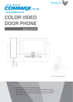
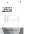
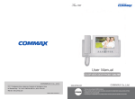
COLOR VIDEO
DOOR PHONE
Model No. CDV-72BE
a513-11, Sangdaewon-dong, Jungwon-gu, Seongnam-si, Gyeonggi-do, Korea
Int’l Business Dept. Tel.;
: +82-31-7393-540~550 Fax.; +82-31-745-2133
Web site : www.commax.com
Printed In Korea/ 2007.08
Thank you for purchasing our COMMAX product.
Please carefully read this User’s Guide (in particular, precautions for safety)
before using the product and follow the instructions to use your productexactly.
The company is not responsible for any safety accidents caused in abnormal
operation of the product.
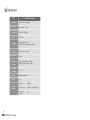
& )! )(- (-,
Warnings and caution
2
1. Parts Name & Functions
4
2. Features and Main Functions
5
3. CDT-180 (Parts Name & Functions)
6
4. Package contents
7
5. System Layout
7
6. Wiring Diagram
8
7. Installation Method
9
8. Operating Description
10
Door Answering & Monitoring
10
Image Recording
10
Review images recorded in the Memory
11
Time setup
12
Camera setup
13
Screen adjustment
14
DECT Phone Registration
14
Trouble shooting
15
Specifications
16
1
+($(",(.-$)(
+($(",(.-$)(
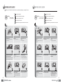
Make sure to follow the instructions to prevent any danger or property losses.
It indicates prohibition.
Warning
Death or serious
injury is expected.
Caution
It indicates prohibition of contact.
An injury or property
losses are expected
It indicates prohibition of disassembly.
It indicates prohibition of contact.
It indicates dos and don’ts.
It indicates dos and don’ts.
It indicates that the plug should be pulled out from the socket.
It indicates that the plug should be pulled out from the socket.
+($("
2
It indicates prohibition.
It indicates prohibition of disassembly.
.-$)(
Do not put the plug in the socket
simultaneously.
It may generate abnormal heat
or cause a fire.
Do not connect to other products
while in use.
It may cause breakdown.
Do not forcibly bend the cord or
put a heavy object on the
product.
It may cause a fire.
If the socket holes are larger
than normal, do not put the
plug.
It may cause an electric shock
or a fire.
Make sure that dust or foreign
substances are not gathered
on the product.
Make sure to prevent foreign
substances from entering the
product.
It may cause a breakdown.
Do not use water, thinner or a
detergent used to wash oil products
when you wash the exterior.
Make sure to wash it by using a dry cloth to
prevent any breakdown or electric shock.
Do not install the product in a
humid place.
It may cause an electric shock or
a fire.
Do not forcibly pull out the
cord from the socket.
If the cord is damaged, it may
cause a fire or an electric shock.
Do not put a heavy object on
the product.
It may cause a breakdown.
Do not disassemble or give an
impact to the product.
Avoid direct rays of the sun or
heating devices at a time of
installation.
Do not put the plug in the
socket with a wet hand.
It may cause an electric shock.
Do not disassemble, repair or
modify the product.
It may cause a fire, an electric shock
or an injury due to malfunction of the
product.
Do not use AC circuit breaker.
It may cause an electric shock.
Install the product in a flat and
stable place.
Otherwise, it may not function
properly.
Pull the plug if the product is
not used for a long time.
If the product generates strange
sound, make sure to pull the
plug immediately and contact
Commax service center.
3
+-,' (.(-$)(,
-.+ ,('$(.(-$)(
1) Features
7” Wide TFT-LCD
Surface mount type
Free voltage power source
OSD (On screen Display)
2) Main function
Door Answering & Monitoring
Image Max of recording 128 cuts : Auto & Manual record
Door Open function
CCTV Camera connectable
4 Door camera units (Inter-mixture with door cameras or
CCTV cameras)
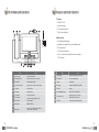
No.
4
Name
No.
Name
Control the call volume
12 Review button
Review the stored pictures in memory
"Monitoring" button
View screen by door camera or talk
13 Delete button
Delete a recorded image
Record button
Record images manually
14 Speaker
Audio speaker
4
"Door Release" button
Operate on Door release of door camera,
15 Mood lamp
Creates pleasant light display at night
5
"Up" button
Up direction key
16 Handset
Handset
6
"Left" button
Left direction key
17 Auto recording status Lamp
Status of auto recording mode
7
"Down" button
Down direction button
8
"Power" switch
Control the power supply of product
18 Power source code
Supply power source of product
(AC100V-240V/ 50Hz, 60Hz)
9
"Enter" button
Execution button
19 Terminals
Connecting door cameras and pstn
1
Volume control
2
3
10 "Right" button
Right direction key
11 Menu button
Camera set, Dect Register set, Time set,
Auto record set, image delete
5
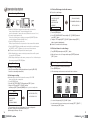
%" )(- (-,
+-,' .(-$)(,
Receiver
LED
-Receiving incoming call
-Receiving new message
message
-Flash at new message
Color LCD
Function display
Redial / Back / Clear
Monitor & Handset
User manual
Wall Mount Bracket
Fixing Screw
Up/Down Key
-Menu Up/Down
-Setting change
Menu button
Menu/ OK/ Option
Connector 4P(4EA)
Left/Right Key
-Cursor movement
-Right : Open redialing list
Down :
Hot key for Phone book
Function Key
Menu / OK / Option
Function Key
Redial / Back / Clear
Connector 2P(1EA)
/,- '/).-
Headset Outlet
TALK Key
-Making a call
-Handsfree
-Speaker On Phone
END Key
-End Call
-Previous
-Move to standby mode
(Push long)
-Handset on/off (hold down)
Key
Toggle bell sound
on/off
Closing button
-Hold to close button
-Changing capital/
small letter on alphabet
Door Camera
cctv
Door Open
Mic
Recall and Pause button
-Recall (Push shortly)
-Pause
(Hold for over 3 seconds)
Connectable Units
Door Camera: 4 units (Max) -> inter-mixture with a CCTV Camera or a door Camera
with CCTV Camera
Wiring
Camera : 30M(at 0.5mm)/ 50M (at 0.65mm)/ 70M(at 0.8mm)
CCTV camera : Coaxial Cable
6
7
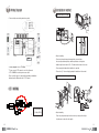
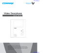
$+$("$"+'
(,-&&-$)(' -#)
Installation method of monitor
Please carefully connect wiring terminal on polarity
145cm
or
Notes for installing
-Please keep the product away from magnetism, severe moisture,
direct sun rays and nearby heater, which may influence on the product.
-Suitable height for main unit is 1450 ~ 1500mm from the bottom to the screen.
Wiring diagram for CCTV Camera
Please connect CCTV camera to one of the 4 channels
- CCTV CAMERA is needed a power source itself.
- Please select the type of Coaxial Cable depending on installation
distance from the Mater unit to the CCTV Camera.
-Please arrange the handset after installation is completed
-Please refer to [7. Camera Setup] regarding the Installation of Camera unit.
Installation method of camera (at DRC-4CH)
SHIELD
: BLUE (GND)
CONE
ڢکڤڭڤڲ ڱگڞڞ
: White (VIDEO)
Notes for installing
-Please keep the product away from direct sun rays or strong reflected light.
It might cause to reduce the video quality.
8
9
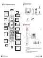
* +-$)( ,+$*-$)(
2-3. Delete all the image storsd in the memory
♠ Delete all recorded images
1. Door Answering & Monitoring
[MENU]
1. AUTO RECORD SET
2. CAMERA SET
[DEL WHOLE IMAGES]
THE NUMBER OF IMAGES : 56
3. DECT RESISTER
4. TIME SET
5. DEL WHOLE IMAGES
ARE YOU SURE : NO
When the [CALL] button is pressed from a camera unit, you can hear the
chime sound from the monitor The monitor displays the visitor
as well as the number of Camera on the screen (Duration of on-screen : 30 sec)
You can pick up the handset to talk.
If the screen is off while you e talking, you can press the [MONITOR] button
in order to talk again. (Duration of talking: 60 sec)
Press the [OPEN] button to open the door.
While you press the button, the relay connection of door camera will be sustained.
Press the [MONITOR] button in standby mode to monitor the door, and then press
the [RIGHT() or LEFT ()]button to see the screen of the next camera.
♠ No Plcamera connected in Setup mode, that channel is passed.
While talking with a door camera or monitoring a camera, the door will be opened
if you press the [OPEN] button.
While talking or monitoring over the camera, you may record 1 cut of visitors image in
Press the [MENU] button
Select “DEL WHOLE IMAGES” menu using the [UP]/ [DOWN]button and
press [ENT] button.
Change to “YES” using the [LEFT], [RIGHT] buttons and press [ENT]
button to go back to standby mode.
♠ It takes 5 seconds to delete all images
2-4 Delete each frame of recorded image.
Press [REVIEW] button and press the [ENT ] button.
Make a full sereen of one of 6 images and then press [DELETE] button and
[ENT ] button.
the memory pressing the [RECORD] button.
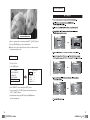
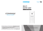
3. Review Image recorded in the Memony
2. Image Recording
2-1. Image recording manually
While you are monitoring or talking through a door unit, press the [RECORD.]
button to record an image automatically.
♠ Th i s i s a Function for viewing recorded images.
Press [REVIEW] button.
6 Recorded images are shown on a screen from the last recorded one.
2-2. Auto image recording
♠ Automatically record the visitor
s pictures the memory of CDV-72BE
when you set the units on away mode.
Press the [MENU] button
Select the “AUTO RECORD SET” in Menu and press [ENT ] button.
Change to “YES” using [LEFT], [RIGHT]buttons,
and then press [ENT] button and [MEMU]button to go back to standby mode.
[MENU]
1. AUTO RECORD SET
2. CAMERA SET
3.DECT RESISTER
[AUTO RECORD SETUP]
The green lamp on the top of it blinks when it is in auto recording mode.
10
2
3
01-28 11:12:33
01-30 12:15:42
02-01 13:20:05
4
5
6
02-05 18:41:00
02-06 09:35:00
L/R : POINT
U/D : PAGE
02-06 09:35:00
ENT = ZOOM
1/4
AUTO RECORD : YES
4. TIME SET
5. DEL WHOLE IMAGES
♠ Visitorspictures are not stored when the lamp is off.
♠ Max capacity of Memory : 128 cuts
1
Go to next 6 images using [UP]/ [DOWN] button,
In order to make full screen of one image, select one using [LEFT], [RIGHT ]
buttons and press [ENT] button.
11
5. Screen Adjustment
2007-01-28 11:12:33 1-1/4
Move to a previous image or a next image using [LEFT], [RIGHT] buttons
Press the [REVIEW] again to go back to standby mode
♠ When it comes to full records with 128 cuts, the first recorded image will be
deleted automatically in order.
4. Time setup
This is to set Time.
Press [ MENU] button
[MENU]
[TIME SETUP]
1. AUTO RECORD SET
2. CAMERA SET
1. YEAR
2. MONTH
2007
01
3. DECT RESISTER
4. TIME SET
3. DAY
4. HOUR
01
01
5. DEL WHOLE IMAGES
5. MINUTE
01
Select ”TIME SET” in the menu and press [ENT ]button
Select one using [UP‚]/ [DOWN] buttons and change the time using
[LEFT], [RIGHT]buttons.
After finishing the setting, press[ENT]button and [MENU]button to
go back to standby mode.
12
13
6. DECT Phone Registration
+).& ,#))-$("
Before usage of any wireless phone, each phone must be registered with
the DECT base unit.
Registering a Wireless Phone
If you think that the product has trouble, please first check below contents before you ask a repair.
Troubles
Registering...
Base
Men
Redia
Exit
Next, program the registration mode from the body.
1. Please connect the
1.The power supply
power supply cord
code is missing or not.
2.The power supply switch 2. Please turn on the power
supply switch (down)
(down) is off or not.
pushing to the right.
A Call operation is not
performed.
1. Please refer to connection
1.The wiring between other
related page and manage.
units is connected correctly
2.
Please
connect correctly
in good order or not.
to the terminal.
2. The wiring is missing or not.
3. Please refer to Room id
3. A Room id is set or not.
setting related page.
(Door, function)
The product does not
produce the sound.
1. A sound volume lies
in minimum or not.
1. Please adjust the sound
volume properly turning
to the right, as you want.
1. There is a strong reflected light behind the
visitor or not.
2. The screen control is
adjusted correctly.
1. Please change the angle
of camera lens.
2. Please initialize the
screen control.
(Call volume, Talk volume)
By pressing the MENU button, chooseDECT Register
Actions
The power supply is
not on.
All works are stopped
Menu >> Handset Set >> Register >> Base # ID >> Enter PIN
(Personal Identification Number: 4-digits) then press the OK button.
The phone will then be registered in the body of the DECT base.
Check Point
and press ENTER to register any phone.
♠ Phone Successfully Registered
When the registration of a phone is complete, a
beepwill sound and the numbers
1-6 will appear. At this time, register any desired number 1-6 to the phone.
(*Any previously registered number will not appear on screen.)
One DECT base is capable of registering up to 6 wireless phones.
The registration may take anywhere from 60 seconds to process.
If the phone fails to register, wait 1 minute before trying to register it again.
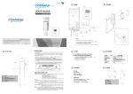
7. Camera setup
♠ CDV-72BE is connectable up to 4 camera units.
Press [MENU]button
The screen is dark.
The screen is strange.
We can see the visitor
image but no voice.
1. The connector on the
handset is properly
inserted to the product?
1.Please put the
connector properly again.
No stored image found
1. Auto recording is
assigned?
1.Please set the status of
“AUTO RECORD“
as “YES”
[MENU]
1. AUTO RECORD SE
2. CAMERA SET
3. DECT RESISTER
4. TIME SET
5. DEL WHOLE IMAGES
[CAMERA SETUP]
1. CAMERA 1
ENABLE
2. CAMERA 2
ENABLE
3. CAMERA 3
ENABLE
4. CAMERA 4
DISABLE
Select [CAMERA SET] menu using [UP] / [DOWN] buttons and press [ENT] button
(Refer to setting related page)
Set up the camera’ s status using [LEFT]/[RIGHT] buttons.
Press [ENT] button and [MENU]button to go back to standby mode
14
The default vale is set to use all four cameras
15
* $!$-$)(
ITEM
Wiring number
Camera : 4 lines on polarity
Rated voltage
AC100-240V~, 50/60Hz
Power consumption
(On operating)
CDV-72BE : 25W (Max.)
Display
7” TFT-LCD
Call sound
Door(individual door):ring/
electronic chime 3 sounds twice repeatedly/
Time for
screen working
Image memory
Communication
distance
Operating
temperature
Dimension
Weight
Wireless
handset
16
CONTENTS (CDV-72BE)
30sec (On call : for 60sec)
128 cuts
To Door camera: 30M(at 0.5mm)/
50M(at 0.65mm)/ 70M(at 0.8mm)
0~ 40
315(W)x175(H)x53(D)
1.7kg
Modulation
TDMA/FSK
Frequency band
1.880GHz ~ 1.900GHz (DECT)
Communication
distance
5M