1
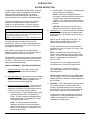
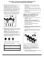
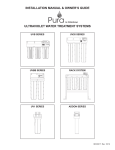
INSTALLATION MANUAL & OWNER’S GUIDE
WATER TREATMENT SYSTEMS
15201 SERIES
REVERSE OSMOSIS
15203 SERIES
MECHANICAL FILTRATION
15202 SERIES
ULTRAVIOLET LIGHT WITH MECHANICAL FILTRATION
INTRODUCTION
SYSTEM DESCRIPTION
b.
The Aquasafe™ Expandable Modular Water Treatment
System consists of patented individual, self-contained,
ready-to-install module assemblies. The module
assemblies may be installed as stand-alone units or
interconnected to form a complete, multi-phase system.
Recovery Rate: The systems are available with
a 25% or 50% Recovery Rating.
NOTE: The Recovery Rating specifies the
percentage of influent water that is delivered as
permeate under open permeate discharge
conditions. The balance of the influent water is
used to rinse the membrane and is then sent to
the drain.
A module assembly may be configured to use a filter
(sediment or activated carbon), reverse osmosis
membrane, or ultraviolet lamp. Filters are selected
based on their Nominal Filter Rating (See Definition).
CAUTION: Systems set for 50% Recovery
Rating must have less than 17ppm hardness.
Definition: Nominal Filter Rating
4.
Specification indicating the approximate size particle (in microns) that
will be retained by the filter. The filter must retain at least 85% of the
particles to achieve a specific micron rating.
Ultraviolet (UV): A module consists of an Ultraviolet
Lamp, Transparent quartz sleeve, Stainless Steel
Channeling Sleeve (or EPCB Carbon Filter) and a
Control Box.
NOTE: A micron equals millionth of a meter or 0.00003937 inches.
Options include a Lamp-Out Circuit (LOC). The
LOC provides an audible alarm or activates a
solenoid valve when the lamp goes out.
A module assembly is available with #13 or #21
filters/sumps. The type of module assembly/system to
be installed is determined by the on-site location and
performance requirements.
The UV module has production specifications of
2 gal/min (7.6 L/min), 4.5 gal/min (17 L/min), or 8.5
gal/min (32 L/min).
Each module assembly/system is shipped with the
hardware required to attach it to the wall and fittings for
inlet/outlet and/or inter-module connections.
NOTE: UV systems are rated according to the
volume of water passing through the system each
minute. This value is stated as gallons per minute
gal/min or GPM) and/or Liters per minute
(L/min or LPM).
The Aquasafe™ System uses unique mounting brackets
that permit individual module assemblies to be rotated
for service. Connections to the system are completed
using standard plumbing fittings.
The 2 gal/min (7.6 L/min) module contains the
UV lamp and a 0.5 micron EPCB Carbon filter.
MODULE ASSEMBLY TYPES AND DESCRIPTIONS
1.
Sediment Removal: This module uses a stringwound, polypropylene filter element rated at
5 microns.
2.
Mechanical Filtration: This module uses an activated
carbon block filter cartridge rated at either 0.5 or 10
microns. The 0.5 micron filter is available as an
Extended Pass Carbon Block (EPCB).
3.
Reverse Osmosis (RO) Filtration: This module uses
a Thin Film Composite membrane element. Since
membranes consistently remove particles less than
1 micron in size, they are rated according to:
a.
The 4.5 gal/min (17 L/min) and 8.5 gal/min
(32 L/min) modules contain a UV Lamp and a
channeling sleeve.
If water conditions fall below the UV CONDITIONS
OF USE (Page iii, Table 1), an additional module or
modules (pre-filters) should be installed upstream of
the UV module.
5.
Daily Production: The #13 Modules have a daily
production specification of 125 gal/day (473
L/day). The #21 modules are available with an
output specification of 125 gal/day (473 L/day)
or 250 gal/day (946 L/day).
CAUTION: The UV lamp requires a start-up period
of one to two minutes in order to achieve full
intensity. Repeated starting of the UV lamp will
shorten its life. Therefore, it is recommended that
the UV lamp remain on at all times during use.
Pre-filters may be may be installed in a variety of
configurations: a string-wound sediment removal
module, an activated carbon module, or a
combination of module types.
NOTE: The daily production specification
designates the volume of permeate (treated)
water produced in 24 hours. Value is shown in
gallons per day (gal/day or GPD) and/or Liters
per day (L/day or LPD).
i
INTRODUCTION
BASIC SYSTEM CONFIGURATIONS
REVERSE OSMOSIS SYSTEMS
MODEL
NUMBER
OUTPUT
(GPD)
15201201
MODULES
FILTER MODULE TYPES
QTY
TYPE
SEDIMENT
125
2
#13
5 MICRON
15201202
125
2
#13
15201203
250
2
#21
15201204
250
2
#21
15201301
125
3
#13
15201302
250
3
#21
CARBON
RINSE WATER FLOW
MEMBRANE
25% RECOVERY
50% RECOVERY
THIN FILM COMPOSITE
375 GPD
125 GPD
THIN FILM COMPOSITE
375 GPD
125 GPD
THIN FILM COMPOSITE
750 GPD
250 GPD
10 MICRON
THIN FILM COMPOSITE
750 GPD
250 GPD
5 MICRON
10 MICRON
THIN FILM COMPOSITE
375 GPD
125 GPD
5 MICRON
10 MICRON
THIN FILM COMPOSITE
750 GPD
250 GPD
10 MICRON
5 MICRON
ULTRAVIOLET SYSTEMS
MODEL
NUMBER
FLOW RATE
(GPM)
15202101
MODULES
FILTER MODULE TYPES
SEDIMENT
CARBON
POWER
SUPPLY
QTY
TYPE
2.0
1
#13
0.5 MICRON EPCB*
120 volt
15202102
2.0
1
#13
0.5 MICRON EPCB*
220 volt
15202103
4.5
1
#13
120 volt
15202104
4.5
1
#13
220 volt
15202105
8.5
1
#21
120 volt
15202106
8.5
1
#21
220 volt
15202201
2.0
2
#13
5 MICRON
0.5 MICRON EPCB
120 volt
15202202
2.0
2
#13
5 MICRON
0.5 MICRON EPCB
220 volt
15202203
4.5
2
#13
5 MICRON
120 volt
15202204
4.5
2
#13
5 MICRON
220 volt
15202205
8.5
2
#21
5 MICRON
120 volt
15202206
8.5
2
#21
5 MICRON
220 volt
15202301
2.0
3
#13
5 MICRON
10 MICRON, 0.5 MICRON EPCB
120 volt
15202302
2.0
3
#13
5 MICRON
10 MICRON, 0.5 MICRON EPCB
220 volt
15202303
4.5
3
#13
5 MICRON
0.5 MICRON
120 volt
15202304
4.5
3
#13
5 MICRON
0.5 MICRON
120 volt
15202305
8.5
3
#21
5 MICRON
10 MICRON
120 volt
15202306
8.5
3
#21
5 MICRON
10 MICRON
220 volt
* EXTENDED PASS CARBON BLOCK CARTRIDGE, 0.5 MICRON RATING - INSTALLED IN SUMP WITH UV LAMP.
MECHANICAL FILTRATION SYSTEMS
MODEL
NUMBER
MODULES
FILTER MODULE TYPES
QTY
TYPE
SEDIMENT
CARBON
15203101
1
#13
15203102
1
#13
15203103
1
#21
15203104
1
#21
5 MICRON
15203201
2
#13
5 MICRON
10 MICRON
15203202
2
#21
5 MICRON
10 MICRON
10 MICRON
5 MICRON
10 MICRON
ii
INTRODUCTION
OPERATION AND MAINTENANCE REQUIREMENTS
CONDITIONS FOR SYSTEM USE, ALL MEDIA TYPES
TABLE 1
System Type
Process Media
Thin Film Composite Membrane
Output Specification
Sediment/Activated Carbon
Ultraviolet
125 GPD
250 GPD
ALL
ALL
Chlorinated/Non-Chlorinated
Chlorinated/Non-Chlorinated
Chlorinated/Non-Chlorinated
Chlorinated/Non-Chlorinated
207-862 kPa (30-125 psig)
207-862 kPa (30-125 psig)
172-862 kPa (25-125 psig)
138-517 kPa (20-75 psig)
7°-35° C (45°-95° F)
7°-35° C (45°-95° F)
4°-38° C (40°-100° F)
3°-40° C (38°-105° F)
pH Range
4.0 - 11.0
4.0 - 11.0
N/A
6.5 - 9.5
Total Dissolved Solids
1500 mg/L
1500 mg/L
N/A
<1500 mg/L
Turbidity**
<1.0 NTU**
<1.0 NTU**
N/A
<1.0 NTU
2 GPM
3 GPM
N/A
N/A
<4.0
<4.0
N/A
N/A
(CaCO3 )
<350
<350
N/A
< 120
Iron
( Fe )
<0.1
<0.1
N/A
< 0.3
Manganese
( Mn )
<0.05
<0.05
N/A
< 0.05
Hydrogen Sulfide
( H2 S )
0.00
0.00
** Nephelometric Turbidity Unit.
Residual Chlorine
( Cl2 )
<2.0
<2.0
*** Silt Density Index: Value stated in SDI units.
Source Water Supply Profile
Community/Private
Feed Water Pressure
1
Feed Water Temperature
Supply Flow
Maximum SDI***
Chemical Parameters
Hardness
3
2
NOTES:
1. A Pressure Regulator may be required if the source water pressure exceeds the maximum for the type of module to be installed.
Multi-Module Systems incorporating an Ultraviolet (UV) module cannot exceed 517 kPa (75 psig).
A Booster Pump may be required if the source water pressure is insufficient to meet the minimum for the type of module to be installed.
Multi-Module Systems incorporating a Reverse Osmosis (RO) module require a minimum of 207 kPa (30 psig).
2. All values shown are in parts per billion (ppm) unless noted otherwise.
3. Reverse Osmosis System rated for 50% Recovery Rating must have less than 17 ppm Hardness.
SERVICE AND ROUTINE MAINTENANCE REQUIREMENTS
TABLE 2
SERVICE REQUIREMENTS
This system contains replaceable treatment components that are critical to the efficiency of the system. These components, by their very nature, have a
finite life span. Compliance with operational, maintenance, and component replacement requirements is essential for this drinking water system to perform
as specified. Replacement of the reverse osmosis membrane, carbon cartridge, or ultraviolet lamp should be with one of identical specifications, as defined
,
by WaterGroup to assure the same efficiency of operation. We strongly recommend that the system user test the product water at regular intervals (six
months minimum) to make sure that the system is operating satisfactorily.
ROUTINE MAINTENANCE REQUIREMENTS
REVERSE OSMOSIS MEMBRANE
ACTIVATED CARBON CARTRIDGE
Replace as required by periodic TDS rejection tests and
Replace every 6 to 12 months,
Production Flow Rate. Maximum recommended service life for
As required
the membrane is 36 months.
iii
ULTRAVIOLET LIGHT
Lamp: Replace every 12 months.
Quartz Sleeve: Clean, replace if damaged.
INTRODUCTION
INSTALLATION REQUIREMENTS
CAUTION: Follow the directions in this Guide when installing your system to ensure that it operates correctly.
CAUTION: The Aquasafe Water Treatment Systems are designed for indoor use only.
LOCATION
HARDWARE
1.
1.
Mount the module using the proper screws or bolts
for the material composition of the selected location.
2.
Mount the module using brackets provided.
Brackets must be installed exactly 6” on center.
A Module may be mounted on any vertical surface
capable of supporting the total weight of all system
modules (any type) when they are full of water.
#13 Module Assembly: 6 pounds.
#21 Module Assembly: 9 pounds.
2.
Modules must have sufficient clearance to permit
easy removal/replacement of cartridges and to clean
the quartz sleeve:
Reverse Osmosis, Carbon, and Sediment
Modules:
#13 or #21: Minimum of 6” below.
Ultraviolet Lamp Modules:
2 GPM: Minimum of 15” above and below.
4.5 GPM: Minimum of 15” above and below.
8.5 GPM: Minimum of 25” above and below.
3.
There must be sufficient clearance at each end of
a module assembly/system to complete source
water line and product water line connections.
4.
A Reverse Osmosis (RO) module assembly must
have easy access to the drain for rinse water. Drain
must have sufficient capacity to carry the rated
system rinse water flow rate (Page ii). Space must
be available so that tubing may be routed without
bends or sharp curves.
5.
NOTE: The number of brackets required for an
installation is determined by the number of modules:
1 module/2 brackets
2 modules/3 brackets
3 modules/4 brackets
SOURCE WATER
CAUTION: System may not be used where water is
microbiologically unsafe or with water of unknown quality
without adequate disinfection before the system.
CAUTION: System may be installed on potable
(drinkable) water supplies only.
1.
Water pressure, temperature, and composition
should be tested to determine system requirements.
2.
Water must meet the parameters listed in the
CONDITIONS FOR USE (Page iii, Table 1). Source
water exceeding chemical parameters requires
pretreatment.
3.
CAUTION: The Thin Film Composite material used
in the membrane may be damaged by chlorine.
A reverse osmosis system installed on a source
water supply containing free chlorine must include
an activated carbon filter before the membrane.
CAUTION: Verify power outlet is grounded and that
it meets or exceeds local electrical codes
CAUTION: Verify that power outlet and control box
are the same voltage rating (120 or 220 volts) before
proceeding with installation.
CAUTION: System will not function properly if water
flow is reversed.
CAUTION: To ensure maximum UV exposure, UV
systems should include pre-filters to process the
water before it reaches the UV lamp. These filters
will remove the suspended solids that may shield the
microbes and make it difficult to obtain sufficient UV
exposure.
Position the system close enough to a grounded
power outlet to permit connection of the control
without an extension cord.
6.
Module assemblies are positioned so that auxiliary
ports are facing forward, away from mounting
surface. In this configuration, water flow direction is
from left to right.
NOTE: Some applications may require the system
be reversed when installed (water flow right to left).
This installation is not recommended, as there is
insufficient space between the module and mounting
surface to install gauges or other monitors.
MULTIPLE MODULE INSTALLATIONS
1.
Module types must be connected in sequence (as
applicable): sediment, carbon, reverse osmosis, and
ultraviolet.
1
MECHANICAL FILTRATION AND REVERSE OSMOSIS MODULES
INSTALLATION AND CONNECTION PROCEDURES
The system must be installed in accordance with applicable city, state, and local plumbing codes.
AquaSafe™ is designed to provide years of trouble-free service if properly maintained.
Retain these instructions for future reference.
PREPARATION
MECHANICAL FILTRATION MODULE
1.
CAUTION: Do not install system on hot water line.
NOTE: Use thread sealing tape (P/N 35700002) on
male threaded connections.
Locate shut off valve on source water line and shut
off water supply.
1.
Install lower brackets as instructed in Section
“MOUNTING BRACKET INSTALLATION” on this
page.
2.
CAUTION: Verify that the module assembly fits
correctly into the lower mounting bracket. If the
space between the mounting brackets is incorrect,
relocate the brackets before proceeding with the
installation.
2.
Identify the module type to be installed:
a.
Mechanical Filtration: The port at the top
center of the head is blocked.
This unit is shipped fully assembled. Refer to
Section “MECHANICAL FILTRATION
MODULE” on this page for instructions
b.
Reverse Osmosis: The port at the top center of
the head has the threaded connection for the
membrane and flow control assembly.
This unit is shipped fully assembled. Refer to
Section “REVERSE OSMOSIS MODULE” on
this page for instructions
c.
Place the module assembly into the lower
mounting bracket.
Ultraviolet: The port at the top center of the
head is open.
This unit is assembled as part of the installation
process. Refer to Section “ULTRAVIOLET
MODULE” on Page 10 for instructions.
3.
Place the upper mounting bracket in position
and attach it to the lower bracket with the mounting
bracket screws.
4.
Connect the source water line to the System Inlet
Port. Connect the product water line to the
Outlet Port.
5.
Open source water shut-off valve. Let the module
run for five minutes and check for leaks. Correct
leaks as necessary.
INSTALLATION
NOTE: Item number callouts in the following Installation
Instructions refer to Page 4, Figure 4 unless noted
otherwise.
REVERSE OSMOSIS MODULE
NOTE: Use thread sealing tape (P/N 35700002) on
male threaded connections.
MOUNTING BRACKET
1.
Determine location for brackets that will provide
adequate clearance (Page 1, Step 2).
2.
Remove the Mounting Bracket Screws (Item 5) and
pull the Upper Mounting Bracket (Item 6) away
from the Lower Mounting Bracket (Item 7).
3.
Pull the module assembly away from the lower
mounting bracket and set the module assembly
aside.
4.
1.
Install lower brackets as instructed in Section
“MOUNTING BRACKET INSTALLATION” on this
page.
2.
CAUTION: Verify that the module assembly fits
correctly into the lower mounting bracket. If the
space between the mounting brackets is
incorrect, relocate them before proceeding with
the installation.
Place the module assembly into the lower
mounting bracket.
Attach the Mounting Brackets (Item 7) to the wall on
6” centers.
2
3.
Place the upper mounting bracket in position
and attach it to the lower bracket with the mounting
bracket screws.
4.
Remove the Sump (Item 19) containing the
membrane (Item 23).
MECHANICAL FILTRATION AND REVERSE OSMOSIS MODULES
INSTALLATION AND CONNECTION PROCEDURES
5.
7.
CAUTION: Hold the membrane firmly to prevent it
from rotating when the elbow is installed
CAUTION: When tightened, rotate the membrane
so that the elbow is pointed toward the drain
connection (See Figure 1). There must be sufficient
space to connect the tubing and to route tubing to
the drain without any kinks or tight bends.
CAUTION: Do not alter the length of the flow
control tubing. To do so will change the system
recovery rating.
Route flow control tubing to the drain connection.
Draw excess tubing into a loop and secure the loop.
8.
Connect the Flow Control Elbow (Item 11) and 1/4”
tubing connector (Item 12) to the threaded drain
connector on the top of the Membrane (Item 23).
CAUTION: Approved air gap is required. See local
plumbing codes.
Connect the flow control tubing to the drain/air gap.
WARNING: USE FDA APPROVED SILICONE
LUBRICANT ON “O” RINGS. DO NOT USE
PETROLEUM-BASED LUBRICANTS.
3/8" NPT ELBOW
MEMBRANE
DRAIN CONNECTION
1/4" TUBING
CONNECTION
9.
CAUTION: Confirm that the “O” ring (Item 15) is in
place and lubricated.
CAUTION: Tighten the sump by hand only. Do
not use tools as they may over-tighten and
damage the sump. Take care not to cut or pinch
the “O” Ring (Item 20).
Install the sump into the Reverse Osmosis
Manifold Head (Item 16).
10. CAUTION: The system will not shut down if the
solenoid is incorrectly installed. See Figure 3 for the
correct flow path.
Figure 1: Membrane Drain Assembly
6.
CAUTION: Verify that the Flow Control Assembly
(Item 13) matches the membrane recovery rate and
output (See Figure 2 and Table 3):
Connect the 3/4” Nipple (Item 2) to the Solenoid
(Item 1) and connect the solenoid to the System
Inlet Port.
CAUTION: The inner diameter of the tubing is
critical to the performance of the flow control. Do not
use standard 1/4” tubing for the flow control.
Connect the flow control tubing to the flow elbow.
Insert the tube until it is fully seated in the connector.
Tighten the nut on the elbow.
FLOW
DI RECTION OF FLOW
1/16”
3/32”
1/8”
Figure 2: Flow Control Tubing Inside Diameters
Flow Control Tube Designation
Table 3
Figure 3: Solenoid Installation and Flow Path
25% Recovery Rating
CAUTION: Verify source water pressure before
connecting system. A Pressure Regulator is
required if pressure exceeds 862 kPa (125 psig).
A Booster pump may be required if pressure is
below 207 kPa (30 psig).
125 GPD - Red Tubing 3/32 in. I.D. x 17 ft., P/N 40600046
250 GPD - Green Tubing 1/8 in. I.D. x20 ft., P/N 40600045
50% Recovery Rating
125 GPD - Yellow Tubing 1/16 in. I.D. x 7 ft., P/N 40600044
250 GPD - Yellow Tubing 1/16 in. I.D. x27 ft., P/N 40600043
11. Connect source water line to the solenoid. Connect
product water line to the Outlet Port.
3
MECHANICAL FILTRATION AND REVERSE OSMOSIS MODULES
INSTALLATION AND CONNECTION PROCEDURES
Item
1
2
3
4
5
6
7
8
9
10
11
12
13
14
15
16
17
18
Description
Valve, Solenoid
Nipple, 3/4”
Connector, Inlet/Outlet 1/2” FPT
Connector, Inlet/Outlet 3/4” FPT
“O” Ring, Connector
Screw, Mounting Bracket
Mounting Bracket, Upper
Mounting Bracket, Lower
Clip, Retaining
Manifold Head, Filtration
Connector, Manifold Head
Elbow, Flow Restrictor Connector
Connector, 1/4" x 3/8”M
Flow Control Assembly (tube, elbow, connector)
125 GPD, 25% Recovery Rate
250 GPD, 25% Recovery Rate
125 GPD, 50% Recovery Rate
250 GPD, 50% Recovery Rate
Cap, Membrane Drain Connection
“O” Ring, Membrane Drain Connection
Manifold Head, Reverse Osmosis Membrane
Retainer, Check-valve
Check-valve, Product Water
Figure 4: Aquasafe
TM
Part No.
Item
34800041
33601004
21202012
21202005
34201041
32101014
22401020
22401022
21202001
21202002
22401021
33606028
33613011
19
20
21
22
40600046
40600044
40600045
40600043
22401012
34201042
22402001
35200030
22401024
23
24
25
Description
Sump
Filter or Membrane #13
Filter or Membrane #21
“O” Ring, Filter Sump
Filter Cartridge, Sediment
String-Wound Polyester, #13 1 Micron
String-Wound Polyester, #13 5 Micron
String-Wound Polyester, #13 10 Micron
String-Wound Polyester, #13 25 Micron
String-Wound Polyester, #21 1 Micron
String-Wound Polyester, #21” 5 Micron
String-Wound Polyester, #21 10 Micron
String-Wound Polyester, #21 25 Micron
Filter Cartridge, Pre-Filter or Post-Filter
Activated Carbon, #13 0.5 Micron
Activated Carbon, #13 10 Micron
Activated Carbon, #21 0.5 Micron
Activated Carbon, #21 10 Micron
Membrane, Thin Film Composite
125 GPD #13
250 GPD #21
Control Box, Electrical
Transformer, Power Supply 120v 50/60
Transformer, Power Supply 220v 50
Reverse Osmosis and Mechanical Filtration Module Assemblies and Interconnections.
4
Part No.
33801110
33801111
34202036
41405001
41405002
41405003
41405004
41405005
41405006
41405007
41405008
33004116
33004117
33004118
33004119
41400074
41400073
44501016
31500006
31500005
REVERSE OSMOSIS MODULE
SUPPORT COMPONENT INSTALLATION PROCEDURE
3.
ELECTRONIC CONTROL BOX
WARNING: DO NOT USE AN EXTENSION CORD TO
RUN ELECTRICAL POWER TO THE SYSTEM.
To connect a wire to the terminal:
WARNING: ELECTRICAL CONNECTIONS MUST
COMPLY WITH ALL LOCAL CODES.
An Electronic Control Box (Item 24) connected to the
solenoid valve regulates system operation. The control
box contains a circuit board, terminal connections, and a
fuse.
The control box operates at 24VAC 50/60Hz. A 24V
transformer is provided with the system (Item 25). The
transformer is plugged into a grounded outlet.
1.
2.
CAUTION: Wiring connections must be secure to
ensure the system operates properly.
Mount the control box in a visible location close to
an electrical outlet and where the ON/OFF switch is
easily accessible for operation.
Unscrew the Box Cover Screws and pull the cover
clear to expose the circuit board and terminal strip.
a.
Thread the wire through the wire nut and
into the control box.
b.
Loosen the screw above the terminal connector.
c.
Insert the wire into the connector as far as it will
go. If the wire does not go in easily, loosen the
connector screw until the wire will go in.
d.
Tighten the connector screw sufficiently to keep
the wire from pulling out of the connector.
4.
Connect the power cord wires from the transformer
to terminals 1 and 2 (24VAC INPUT) on the terminal
block.
5.
Connect the wires from the solenoid to terminals 3
and 4 (INLET VALVE) on the terminal block.
6.
CAUTION: If the AquaSafe RO system is located
downstream from any device that could cut off the
water supply to the system, i.e., water softener or
filter, an automatic power disconnect, or
Pretreatment (P/T) Lockout Device must be used.
NOTE: All terminal callouts in the following steps refer
to the circuit board shown in Figure 5.
Connect a Pretreatment Lockout Device (P/T),
Automatic Shut-off, and/or Auxiliary Relay as
described on Page 6.
7.
Tighten the nut on the strain relief to hold the wires
in place.
8.
CAUTION: Verify that all connections are secure
before proceeding.
Install the box cover and tighten the screws.
JUMPERS BETWEEN
7 & 8 AND 9 & 10
SOLENOID POWER
CORD TO 3 & 4
9.
TRANSFORMER
POWER CORD
TO 1 & 2
CAUTION: Verify that the Power Switch is in the
“OFF” position before continuing with the installation.
Connect the transformer to the electrical outlet.
Figure 5: Circuit Board Connections
10. Turn on the Aquasafe RO System by moving the
Power Switch to the “ON” position.
11. Open source water shut-off valve. Let the system
run for five minutes and check for leaks. Correct
leaks as necessary.
12. Confirm that the system is producing water. System
will be sending water to the drain.
5
REVERSE OSMOSIS MODULE
SUPPORT COMPONENT INSTALLATION PROCEDURE
WARNING: USE FDA APPROVED SILICONE
LUBRICANT ON “O” RINGS. DO NOT USE
PETROLEUM-BASED LUBRICANTS.
CAUTION: The P/T LOCKOUT and TANK LEVEL
SHUT-OFF connections require dry contacts. The
terminal strip accepts dry contact switch signals capable
of handling 50 mA at 24VAC.
INTER-MODULE CONNECTIONS - NEW
INSTALLATION
PRETREATMENT LOCKOUT DEVICE (P/T)
P/T Device Is Not Installed
1.
1.
Determine sequence in which the modules will be
connected (Page 1).
2.
Install Inlet/Outlet Connectors (Item 3).
Install a jumper between terminals 7 and 8
(P/T LOCKOUT) on the terminal block.
P/T Device Is Installed
1.
CAUTION: The P/T Lockout Device is actuated
when the upstream equipment is turned off. To
operate correctly, the P/T Lockout must be
connected to a switch that is closed (the “ON”
position) during normal upstream equipment
operation.
3.
Locate the required switch and move it to the open
(“OFF”) position. Disconnect the equipment from its
power source.
2.
Connect the P/T Lockout wires to the Switch.
3.
Connect wires from the upstream equipment to
terminals 7 and 8 (P/T LOCKOUT) on the terminal
block.
4.
Lubricate O-Rings (Item 4).
b.
Press the connector fully into the connector port
on the manifold head.
c.
Insert the Retainer Clip (Item 8) to lock the
connector in place.
Install Module-to-Module Connectors (Item 10).
a.
Lubricate O-Rings (Item 4).
b.
Press the connector fully into the connector port
on the manifold head.
c.
Insert the Retainer Clip (Item 8) to lock the
connector in place.
Install system (Page 1).
INTER-MODULE CONNECTIONS - EXISTING
INSTALLATION
AUTOMATIC TANK LEVEL SHUT-OFF
Automatic Shut-Off Is Not Installed
1.
a.
NOTE: It is easier to handle the system if water has
been drained completely and the sumps removed.
Install a jumper between terminals 9 and 10
(TANK LEVEL) on the terminal block.
Automatic Shut-Off Is Installed
Determine the type of product water storage system Is
used downstream of the AquaSafe RO unit. Refer to
either the Float Switch or Pressure Switch Installation Kit
Instructions as applicable.
1.
Close inlet and outlet water valves and relieve
system pressure.
2.
CAUTION: Do not attempt to disconnect tubes until
water flow stops and pressure is relieved.
Disconnect source water and product water tubes.
AUXILARY RELAY
CAUTION: The maximum rated draw for the AUX
RELAY terminals is 100 mA. Do not connect a relay that
draws more than the maximum rated amperage.
A provision is provided in the Control Box for connection
of an auxiliary relay. Terminal connections 5 and 6
(AUX RELAY) are reserved for an auxiliary relay. The
circuit board will provide power to the relay when the
system is on.
6
3.
Remove the Mounting Bracket Screws (Item 5) and
pull the upper Mounting Bracket (Item 6) away
from the lower bracket.
4.
Install the additional mounting brackets (Page 2).
5.
Connect additional manifold head(s) in specified
position (Page 1).
6.
Re-install system (Page 1)
MECHANICAL FILTRATION OR REVERSE OSMOSIS MODULE
CLEANING, SANITIZING AND FILTER REPLACEMENT PROCEDURE
RECOMMENDATIONS
HAVE ALL COMPONENTS ON HAND AND READY BEFORE BEGINNING PROCEDURE
A CLEAN WORK AREA AND EQUIPMENT ARE ESSENTIAL TO PROPERLY CLEAN AND/OR DISINFECT THE SYSTEM
(i.e., CLEAN HANDS, TOOLS, WORK SURFACE, AND CONTAINERS)
EQUIPMENT NEEDED
Safety Glasses
Rubber Gloves, Sanitary
Wash Cloth, Clean and Lint-Free
Liquid Dish Soap
Household Bleach – Unscented Only
(5 ¼% Sodium Hypochlorite)
Plastic Storage Bag, 20” Long
REPLACEMENT FILTERS
REPLACEMENT COMPONENTS
Refer to system Parts List for specific component part numbers
Refer to system Parts List for specific component part numbers
1.
Mix mild cleaning solution of dish soap and clean
potable water in plastic bowl.
2.
Close inlet and outlet water supply valves and
relieve system pressure.
3.
9.
CAUTION: Do not attempt to remove sumps until
water flow stops. This reduces pressure inside
the system so sumps may safely be removed.
10. Place a small amount of "O" ring lubricant over
surface of sump "O" ring. Install "O" ring into sump
groove.
TO SANITIZE THE SYSTEM: Complete Steps 11-26.
TO INSTALL FILTERS: Complete Steps 18-26.
IF MEMBRANE IS PERFORMING SATISFACTORILY:
Go to Step 4.
WARNING: WEAR SAFETY GLASSES WHILE
PERFORMING THIS PROCEDURE.
IF MEMBRANE IS DEPLETED OR FOULED:
Discard it and go to Step 11.
WARNING: READ "WARNINGS" INFORMATION ON
BLEACH CONTAINER BEFORE USING CONTENTS.
CAUTION: Use sanitary rubber gloves for this
procedure to avoid contaminating sanitizing solution,
filters, or membrane. Wear gloves whenever
cleaning/ sanitizing system components or handling
new filter/membrane cartridges.
HANDLE SANITIZING SOLUTION CAREFULLY.
AVOID CONTACT WITH UNPROTECTED AREAS.
11. CAUTION: Excessive concentrations of bleach will
damage plastic and rubber components. Rinse all
parts that contact bleach thoroughly with clean
potable water.
Clean membrane outer wrap with washcloth and
cleaning solution. Do not immerse membrane in
solution. Do not scrub membrane wrap with
abrasive cleaners. Rinse membrane well with clean
potable water.
5.
Place membrane into clean plastic bag, close bag.
6.
Remove sump "O" rings and wash them with
cleaning solution. Rinse them well with clean
potable water. Inspect them for damage
(i.e., nicks, scratches). Replace damaged "O" rings.
7.
Clean filter sumps and manifold ports, inside and
outside, with washcloth and cleaning solution. Do
not use abrasive materials.
8.
Rinse manifold and sumps with clean potable water.
Inspect manifold and sump "O" ring groove area for
damage (i.e., nicks or scratches). Replace damaged
components.
WARNING: USE FDA APPROVED SILICONE
LUBRICANT ON “O” RINGS. DO NOT USE
PETROLEUM-BASED LUBRICANTS.
Remove each sump by turning it counter-clockwise.
Remove each filter cartridge as its sump is removed.
Discard filters.
4.
Plastic Bucket
“O” Ring Lubricant, Silicone Based
(P/N 30300026)
Mix sanitizing solution of 1/3 teaspoon (1.5 ml) of
household bleach and 1 gallon (3.8 L) of clean,
potable water in the bucket. Mix solution well.
12. CAUTION: Tighten sumps by hand only. Do not
use tools as they will over-tighten and damage
sumps. Take care not to cut or pinch “O” rings.
Add 8 oz. (236 ml) of sanitizing solution to each
sump and install them onto the manifold (do not
install filters or membrane at this time). Tighten
each sump by hand only.
7
MECHANICAL FILTRATION OR REVERSE OSMOSIS MODULE
CLEANING, SANITIZING AND FILTER REPLACEMENT PROCEDURE
13. Slowly open source water supply valve.
20. Turn feed water valve slowly to open position.
14. Open outlet valve. Close valve as soon as water
begins to flow from port.
21. Confirm system is producing water. Unit will be
sending rinse water to drain.
15. Wait 5 minutes, then close source water supply
valve.
22. Open outlet valve. Let water flow until all air has
been expelled from the system.
16. Wait 25 minutes, then open outlet valve and let
water flow to drain.
23. Close outlet valve. Wait 5 minutes check
connections for leaks, and correct as necessary.
17. CAUTION: Do not attempt to remove the sumps
until water flow stops. This releases the water
pressure within the system so sumps may safely be
removed.
24. Allow system to operate for at least 30 minutes.
25. Sanitize the Product Water Storage Tank:
Atmospheric Tank: See instructions on Page 9.
Remove sumps and dispose of water. Rinse sumps
and manifold ports thoroughly with clean potable
water.
Hydropneumatic Tank: Use Tank Sanitizing Kit
(P/N 42903007).
26. System is ready to use. Should there be any
aftertaste or odor, drain storage tank and repeat
Steps 24 and 25.
18. CAUTION: Do not remove protective plastic bag
from replacement filter/membrane cartridges until so
instructed.
Install "O" rings into sumps. Open top of filter bag
enough to expose filter cap and "O" ring grooves.
Place a small amount of "O" ring lubricant on surface
of each "O" ring.
19. CAUTION: Tighten sumps by hand only.
Do not use tools as they will over-tighten and
damage sumps. Take care not to cut or pinch
“O” rings.
Install filter and membrane cartridges. Hold
cartridge by its protective plastic bag and insert
cartridge into manifold. Slide bag from cartridge and
discard. Replace sump as each cartridge is
installed.
8
ATMOSPHERIC PRODUCT WATER STORAGE TANK
CLEANING AND SANITIZING PROCEDURE
RECOMMENDATIONS
HAVE ALL COMPONENTS ON HAND AND READY BEFORE BEGINNING PROCEDURE
A CLEAN WORK AREA AND EQUIPMENT ARE ESSENTIAL TO PROPERLY CLEAN AND/OR DISINFECT THE SYSTEM
(i.e., CLEAN HANDS, TOOLS, WORK SURFACE, AND CONTAINERS)
EQUIPMENT NEEDED
Safety Glasses
Rubber Gloves, Sanitary
Wash Cloth, Clean and Lint-Free
Liquid Dish Soap
Household Bleach – Unscented Only
(5 ¼% Sodium Hypochlorite)
Plastic Bucket
“O” Ring Lubricant, Silicone Based
(P/N 30300026)
WARNING: THESE PROCEDURES ARE INTENDED FOR GENERAL USE ONLY. IF STORAGE TANK
MAY BE CONTAMINATED WITH UNKNOWN SUBSTANCES, A WATER ANALYSIS BY A CERTIFIED
LABORATORY MUST BE PERFORMED. DISCARD ANY CONTAMINATED TANK.
CAUTION: All storage tanks must be sanitized when installed. Tanks should be cleaned and sanitized at
least once a year.
CLEANING PROCEDURE
DISINFECTION PROCEDURE
1.
Turn off the system by moving the Electronic Control
power switch to the “OFF” position.
WARNING: WEAR SAFETY GLASSES AND
SANITARY RUBBER GLOVES WHILE PERFORMING
THIS PROCEDURE.
2.
Turn off all electrical equipment connected to the
storage tank i.e., UV, ozone, re-pressurizing pump,
re-circulating pump, etc.
WARNING: READ THE "WARNINGS" ON THE
BLEACH CONTAINER BEFORE USING.
2.
Turn the tank valve to the “OFF” position.
WARNING: HANDLE SANITIZING SOLUTION
CAREFULLY. AVOID CONTACT WITH
UNPROTECTED AREAS.
3.
Disconnect supply line to tank and output line to
point-of-use delivery device.
4.
Connect line from tank output port to drain.
5.
Open tank valve and drain the tank.
6.
CAUTION: Do not use brushes or abrasives that
will scratch the inside tank surface or components.
Clean the inside of the tank with mild dish soap and
potable water. Scrub the side, bottom, and top of
the tank. Scrub the outside surface of all lines,
tubing, and connectors inside the tank.
7.
Rinse the tank thoroughly with clean potable water.
Make sure all surfaces are rinsed well.
9
1.
Mix a sanitizing solution of 6 ml (0.2 oz) of
household bleach for each 3.8L (1 gallon) of clean,
potable water in the bucket. Mix the solution well.
2.
Swab the inside of the tank with the sanitizing
solution. Swab the side, bottom, and top of the tank.
Swab the outside surface of all lines, tubing, and
connectors inside the tank.
3.
Wait 30 minutes and repeat Step 2.
4.
Open tank valve and drain the tank.
5.
Rinse the tank several times with clean potable
water. Make sure all surfaces are rinsed well.
6.
Reconnect tank supply line and output line to
delivery device.
7.
System is ready for use. Should there be any
aftertaste or odor, repeat Step 5.
ULTRAVIOLET MODULE
INSTALLATION AND CONNECTION PROCEDURE
WARNING: NEVER LOOK DIRECTLY AT A LIGHTED UV LAMP.
ULTRAVIOLET RAYS CAN BE HARMFUL TO EYES.
NEVER INSTALL SYSTEM UPSTREAM FROM PUMP.
ASSEMBLY IS REQUIRED BEFORE CONNECTION. FOLLOW INSTRUCTIONS CAREFULLY!
3.
Insert the Quartz Sleeve (Item 4) into the manifold
head from the bottom. Push the sleeve gently,
through the head, until about 1 1/2" of the sleeve
appears above the head.
4.
Install “O” rings removed in Step 1 around the
outside of open end of the Quartz Sleeve (Item 4).
Locate them approximately 1/2" from one end of the
quartz sleeve.
5.
Push the quartz sleeve back, down into the opening
in the center of the Manifold Head (Item 15). Press
it down into the manifold head until the “O” rings
seat.
6.
Place the ultraviolet holder cap over the exposed
end of the quartz sleeve. Press down gently to fully
insert the sleeve and seat the “O” rings. Thread the
o-ring retaining cap onto the head and tighten by
hand only.
7.
Remove two screws (Item 11) from the UV head.
Place the module assembly into the lower
mounting bracket.
8.
Insert the UV lamp into the connector on the Power
Supply (Item 17)
Place the upper mounting bracket in position
and attach it to the lower bracket with the mounting
bracket screws.
9.
Insert the UV Lamp (Item 16) into the quartz sleeve.
ULTRAVIOLET LAMP MODULE
NOTE: All Item number callouts refer to the following
Illustrated Parts Lists unless noted otherwise:
EPCB UV SYSTEMS: Page 10, Figure 6
CHANNELING SLEEVE UV SYSTEMS: Pages 10 and
11, Figures 7 and 7A.
1.
Remove the Mounting Bracket Screws (Item 10) and
pull the Upper Mounting Bracket (Item 9) away
from the Lower Mounting Bracket (Item 8).
2.
Pull the module assembly away from the lower
bracket and set the module assembly aside.
3.
Install lower brackets as instructed on Page 2.
4.
CAUTION: Verify that the module assembly fits
correctly into the lower mounting bracket. If the
space between the mounting brackets is
incorrect, relocate them before proceeding with
the installation.
5.
10. Attach the bracket on the power supply cord to the
UV Head using screws removed in Step 7.
LAMP AND QUARTZ SLEEVE INSTALLATION
11. CAUTION: Tighten sumps by hand only. Do not
use tools as they will over-tighten and may damage
sump. Take care not to cut or pinch “O” rings or
gaskets. Use sump wrench for removal only.
WARNING: THE UV LAMP AND QUARTZ SLEEVE
ARE VERY FRAGILE. THEY ARE SHIPPED IN A
SEPARATE CARTON TO AVOID BREAKAGE.
Replace sump and contents.
WARNING: DO NOT OPEN CARTON IF YOU HEAR
THE SOUND OF BROKEN GLASS. CONTACT YOUR
HYDROTECH DEALER FOR REPLACEMENT PARTS.
1.
12. Connect the source water to the System Inlet Port.
Connect the product water to the Outlet Port.
Remove the sump and contents:
13. CAUTION: UV lamp should remain on at all times.
Lamp requires 1-2 minutes to start up.
EPCB UV SYSTEMS: EPCB Filter (Item 3)
CHANNELING SLEEVE UV SYSTEMS: Channeling
Sleeve (Item 3).
Plug in transformer.
14. Open source water shut-off valve and output valve.
Allow the system to run for 5 minutes. Correct leaks
as necessary.
2. Remove Ultraviolet Lamp Holder Cap (Item 12)
and two “O” Rings (Item 13) at the open port in the
UV Head (Item 15).
10
ULTRAVIOLET MODULE
INSTALLATION AND CONNECTION PROCEDURE
Item
1
2
3
4
5
6
7
8
9
10
11
12
13
14
15
16
17
18
19
Item
1
2
3
4
5
6
7
8
9
10
11
12
13
14
15
16
17
Description
Sump, Ultraviolet Lamp or Filter Cartridge
“O” Ring, Sump
Activated Carbon Filter, 0.5 Micron EPCB
Activated Carbon Filter, 10 Micron
Sleeve, Quartz #13, with “O” Ring
Clip, Retaining
“O” Ring, Connector
Connector, Inlet/Outlet 1/2” FPT
Connector, Inlet/Outlet 3/4” FPT
Bracket, Mounting Lower
Bracket, Mounting Upper
Screw, Mounting Bracket
Screw, Power Cord Holding Bracket
Cap, Ultraviolet Lamp Holder
“O” Ring, Cap
Restrictor, Flow 2 GPM
Manifold Head, Ultraviolet
Lamp, Ultraviolet #11
Transformer, Power Supply, #11 120v
Transformer, Power Supply, #11 220v
Part No.
33801110
34202035
41405009
41405010
44303203
22402001
34201041
21202012
21202005
22401022
22401020
32101014
32701007
22401012
34202021
40600047
22402001
36002017
44302409
44302410
20
21
TM
Description
Sump, Ultraviolet Lamp or Filter Cartridge #13
Sump, Ultraviolet Lamp or Filter Cartridge #21
“O” Ring, Sump
Channeling Device with Gasket #13
Channeling Device with Gasket #21
Gasket, Channeling Device
Sleeve, Quartz #13 with “O” Rings
Sleeve, Quartz #21 with “O” Rings
Clip, Locking
“O” Ring, Connector
Connector, Inlet/Outlet 1/2” FPT
Connector, Inlet/Outlet 3/4” FPT
Bracket, Mounting Lower
Bracket, Mounting Upper
Screw, Mounting Bracket
Screw, Power Cord Holding Bracket
Cap, Ultraviolet Lamp Holder
“O” Ring, Cap
Restrictor, Flow
4.5 GPM
8.5 GPM
Manifold Head, Ultraviolet
Lamp, Ultraviolet, #11
Lamp, Ultraviolet, #21
Transformer, Power Supply, #11 120v
Transformer, Power Supply, #11 220v
Transformer, Power Supply, #21 120v
Transformer, Power Supply, #21 220v
Manifold Head, Filtration
Filter Cartridge, Sediment
String-Wound Polyester, #13 1 Micron
String-Wound Polyester, #13 5 Micron
String-Wound Polyester, #13 10 Micron
String-Wound Polyester, #13 25 Micron
String-Wound Polyester, #21 1 Micron
String-Wound Polyester, #21 5 Micron
String-Wound Polyester, #21 10 Micron
String-Wound Polyester, #21 25 Micron
Connector, Manifold Head
Filter Cartridge, Pre-Filter
Activated Carbon, #13 0.5 Micron
Activated Carbon, #13 10 Micron
Activated Carbon, #21 0.5 Micron
Activated Carbon, #21 10 Micron
TM
Figure 6: Aquasafe Ultraviolet Lamp with Activated
Carbon Filter Module Schematic and Parts List
Part No.
33801110
33801111
34202035
44301017
44301018
36099205
44303203
44303204
21202001
34201041
21202012
21202005
21201022
21201020
32101014
32701007
22401012
34202021
40600048
40600049
22402001
36002017
44303101
44302409
44302410
44302411
44302412
22402002
41405001
41405002
41405003
41405004
41405005
41405006
41405007
41405008
22401021
33004116
33004117
33004118
33004119
Figure 7: Aquasafe Ultraviolet and Mechanical
Filtration Module Parts List
11
ULTRAVIOLET MODULE
INSTALLATION AND CONNECTION PROCEDURE
AquaSafe™ Ultraviolet System
1 Module Unit, 4.5 or 8.5 GPM
with UV Lamp and Stainless Steel Sleeve
AquaSafe™ Ultraviolet and Mechanical Filtration System
2 Module Unit, 4.5 or 8.5 GPM
with Sediment Filter and UV Lamp
AquaSafe™ Ultraviolet and Mechanical Filtration System
3 Module Unit, 4.5 or 8.5 GPM
with Sediment Filter, Carbon Filter, and UV Lamp
Figure 7A: Aquasafe
TM
Ultraviolet and Mechanical Filtration Module Assemblies and Interconnections Schematic
12
ULTRAVIOLET MODULE
OPERATIONAL REQUIREMENTS
It is important that any water treatment system be properly maintained to ensure consistent water
quality. Information provided on this page is of a general nature. For more detailed information, refer
to the Cleaning, Disinfecting, and Filter Replacement Procedure on Page 14, the Mounting
Bracket/Plumbing Installation Instructions (Pages 1 and 2), and Installation Instructions for the
appropriate system (Page 2 for Mechanical Filtration and RO, Page 10 for UV Lamp).
QUARTZ SLEEVE
WARNING: DISCONNECT LAMP FROM OUTLET
BEFORE PERFORMING ANY MAINTENANCE
PROCEDURE.
The quartz sleeve should be wiped clean each time the
module is serviced. This will enable the lamp to provide
the maximum level of UV exposure.
CLEANING
The 4.5 and 8.5 GPM systems have a stainless steel
channeling sleeve that stays in the sump when it is
removed from the manifold head. A rubber gasket seals
the stainless steel sleeve against the outlet port inside
the head. This gasket may stay attached to the head,
use care not to lose this gasket.
The inside of the system and the quartz sleeve should
be cleaned each time the filters are changed. Clean all
parts (except the filters and electronic parts) with the
specified cleaning solution and rinse them thoroughly
with RO, distilled, or de-ionized water.
NOTE: Presence of iron or general poor water quality
will require that the system be inspected and the
quartz sleeve cleaned more frequently.
The ultraviolet lamp must be fully inserted into the
sleeve, with no kinks or pinches in the electrical cable. If
the lamp is not fully inserted, the system will not perform
to its rated specifications.
SUMP REMOVAL
WARNING: PULL THE SUMP STRAIGHT DOWN TO
AVOID BREAKING THE QUARTZ SLEEVE.
FILTER REPLACEMENT
WARNING: PULL FILTERS STRAIGHT DOWN TO
AVOID BREAKING THE QUARTZ SLEEVE.
Make sure system water pressure has been relieved
before attempting to loosen the sump. Pull the sump
straight down until it clears the quartz sleeve, do not
move it from side-to-side.
™
™
CAUTION: Use only Aquasafe filters. Aquasafe
filters are specially designed to work in the ultraviolet
™
disinfection process. Use of non- Aquasafe filters voids
the warranty.
If channeling sleeve is installed, make sure it is in the
sump when the sump is removed. If an EPCB filter is
installed, remove it separately by pulling it straight down
until it clears the quartz sleeve.
Filters will normally last approximately four to six
months. Filter life will vary due to water conditions. A
reduced flow rate or deteriorating water quality indicates
that filters must be changed.
Remove the EPCB Carbon Filter. Pull on the filter with a
gentle twisting motion. This will loosen the “O” ring seal
holding the filter in the head, allowing the filter to be
removed
The pre-filters, and EPCB filter for the 2-gpm systems,
may need to be changed more often, depending on your
specific water conditions.
“O” RINGS
UV LAMP
WARNING: USE FDA APPROVED SILICONE
LUBRICANT ON “O” RINGS. DO NOT USE
PETROLEUM-BASED LUBRICANTS.
®
CAUTION: Use only PURA UV lamps as they are
™
specifically designed for the Aquasafe system. Use of
®
non- PURA UV lamps voids the warranty.
Lubricate each “O” ring to ensure a proper seal.
Lamps must be changed every twelve months. While
UV lamps rarely burn out, they do lose their disinfection
power.
Replace any “O” Ring that has been cut, pinched, or
deformed in any way. Make sure the mounting grooves
are clean and free of damage i.e., nicks or scratches.
13
ULTRAVIOLET MODULE
CLEANING, SANITIZING, AND CARTRIDGE REPLACEMENT PROCEDURE
RECOMMENDATIONS
HAVE ALL COMPONENTS ON HAND AND READY BEFORE BEGINNING PROCEDURE
A CLEAN WORK AREA AND EQUIPMENT ARE ESSENTIAL TO PROPERLY CLEAN AND/OR DISINFECT THE SYSTEM
(i.e., CLEAN HANDS, TOOLS, WORK SURFACE, AND CONTAINERS)
EQUIPMENT NEEDED
Safety Glasses
Rubber Gloves, Sanitary
Wash Cloth, Clean and Lint-Free
Liquid Dish Soap
Household Bleach – Unscented Only
(5 ¼% Sodium Hypochlorite)
Plastic Bucket
“O” Ring Lubricant, Silicone Based
(P/N 30300026)
REPLACEMENT FILTERS
REPLACEMENT UV COMPONENTS
Refer to system Parts List for specific component part numbers
Refer to system Parts List for specific component part numbers
CLEANING PROCEDURE
8.
Rinse sumps and heads thoroughly.
CAUTION: Clean all parts (except filters and electronic
parts) with the specified cleaning solution and rinse them
with RO product, distilled, or de-ionized water.
9.
For 4.5 and 8.5 GPM Models only: Clean and
rinse the Stainless Steel Channeling Sleeve (Item 3)
and Sleeve Gasket.
NOTE: Refer to individual System Assembly and
Activation Procedures to identify specific components
matching the descriptions shown in this procedure.
1.
Disconnect system from electrical outlet.
2.
Mix a mild cleaning solution of dish soap and clean
potable water in the plastic bucket.
3.
Close feed water supply valve and open outlet valve
to relieve system pressure.
4.
CAUTION: Do not attempt to remove sumps until
water flow stops. This reduces pressure inside the
system so sumps may be safely removed.
10. Inspect head and sump “O” ring groove area for
damage (i.e., nicks or scratches). Replace damaged
components.
WARNING: USE FDA APPROVED SILICONE
LUBRICANT ON “O” RINGS. DO NOT USE
PETROLEUM-BASED LUBRICANTS.
11. Lubricate the sump “O” ring. Install the “O” ring into
the filter sump groove.
DISINFECTION PROCEDURE
WARNING: NEVER LOOK DIRECTLY AT A LIGHTED
UV LAMP.
Remove each sump. Use sump wrench to remove
stubborn sumps. Remove each filter as its sump is
removed. Discard the filters.
5.
WARNING: WEAR SAFETY GLASSES AND
SANITARY RUBBER GLOVES WHILE PERFORMING
THIS PROCEDURE.
WARNING: READ THE "WARNINGS" ON THE
BLEACH CONTAINER BEFORE USING.
CAUTION: Use sanitary rubber gloves for this
procedure to avoid contaminating cleaning solution
or filters. Wear gloves whenever cleaning
components or handling new filters.
WARNING: HANDLE SANITIZING SOLUTION
CAREFULLY. AVOID CONTACT WITH
UNPROTECTED AREAS.
CAUTION: If quartz sleeve is removed or twisted,
replace “O” rings.
Clean quartz sleeve carefully using vinegar to
remove calcium carbonate deposits. Do not use
abrasive materials. Rinse sleeve thoroughly.
Replace any sleeve that is damaged or will not come
completely clean.
6.
Remove sump “O” rings and wash them with
cleaning solution. Rinse “O” rings thoroughly.
Inspect “O” rings for damage (i.e., nicks or
scratches). Replace damaged “O” rings.
7.
Clean sumps and heads, inside and outside with
washcloth and cleaning solution. Do not use
abrasive materials.
1.
Disconnect system from electrical outlet.
2.
CAUTION: Excessive concentrations of bleach will
damage plastic and rubber components. Rinse all
parts that contact bleach thoroughly with clean
potable water.
Mix a sanitizing solution of 59 ml (1/4 cup) of
household bleach and 177 ml (3/4 cup) of clean,
potable water in the bucket. Mix the solution well.
14
ULTRAVIOLET MODULE
CLEANING, SANITIZING, AND CARTRIDGE REPLACEMENT PROCEDURE
3.
UV LAMP REPLACEMENT PROCEDURE
CAUTION: Use care when sanitizing UV head. Do
not get the UV control module or connectors wet.
CAUTION: Refer to individual System Assembly and
Activation Procedures to identify specific components
matching the descriptions shown in this procedure.
CAUTION: Tighten sumps by hand only. Do not
use tools as they will over-tighten and may damage
sump. Take care not to cut or pinch “O” rings or
gaskets. Use sump wrench for removal only.
Add 237 ml (1 cup) of sanitizing solution to the sump
that contains the UV lamp.
4.
Turn on UV System.
5.
Slowly open the feed water supply valve.
6.
Open output valve and keep it open until a chlorine
smell is detected, then close it.
7.
WARNING: WATER LINES DOWNSTREAM FROM
UV HOUSING MUST BE DISINFECTED TO
DESTROY ANY BACTERIA THAT MIGHT REMAIN
IN THE PIPES.
Disconnect system from electrical outlet.
2.
Shut feed water supply valve and open downstream
faucet to relieve system pressure.
3.
CAUTION: Do not attempt to remove sumps until
water flow stops. This reduces pressure inside the
system so sumps may be safely removed.
CAUTION: Use care when sanitizing UV head. Do
not get the UV control module or connectors wet.
Remove sump from UV head and set aside.
WARNING: DO NOT ATTEMPT TO REMOVE QUARTZ
SLEEVE. DAMAGE TO SYSTEM AND PERSONAL
INJURY MAY OCCUR IF THE SLEEVE IS REMOVED
INCORRECTLY. CONTACT YOUR DEALER IF
QUARTZ SLEEVE IS BROKEN OR NEEDS
REPLACEMENT.
Verify disinfection solution has reached every water
outlet downstream of UV system. Solution must
remain in the system for at least four hours.
8.
1.
Open outlet valve and let water flow for 5 minutes to
flush disinfection solution from the water lines.
4.
FILTER REPLACEMENT PROCEDURE
Clean quartz sleeve carefully using vinegar to
remove hardness. Do not use abrasive materials.
Rinse sleeve thoroughly with RO, distilled, or
de-ionized water. Replace any sleeve that is
damaged or that will not come completely clean.
Perform Cleaning Procedure (Page 14, steps 1-11).
CAUTION: Refer to Exploded Schematic for your
system to ensure each filter is installed in the correct
position.
1.
CAUTION: Do not remove protective plastic bag
from filters. Open top of bag only enough to
expose top of filter.
CAUTION: Do not use a petroleum-based lubricant
on “O” rings.
5.
Gain access to UV lamp by removing the Screws
(Item 11) holding the Power Supply (Item 17)
bracket to the UV Manifold Head (Item 15).
6.
CAUTION: Use care not to break UV lamp or
dislodge quartz sleeve.
Lubricate the O-Rings and install the filters into the
appropriate sump. Hold filter by its protective plastic
bag and insert the filter into the sump.
3.
CAUTION: Place the lamp in a location where it
is unlikely to be broken before it may be safely
discarded
Remove UV lamp by gently lifting the cable
connecting the four-pin socket to the UV lamp.
Grasp UV lamp and four-pin socket firmly and
separate lamp from connector
CAUTION: Tighten sumps by hand only. Do not
use tools as they will over-tighten and may damage
sump. Take care not to cut or pinch “O” rings or
gaskets. Use sump wrench for removal only.
Slide bag from filter and discard. Replace each
sump as each filter is installed.
4.
CAUTION: Do not touch quartz sleeve or UV lamp
with bare hands. Fingerprints will reduce the
effectiveness of the light.
7.
Turn on water supply and check for leaks.
CAUTION: Hold replacement UV lamp by the
ceramic ends only. Do not touch the glass. Clean
glass with isopropyl alcohol if necessary.
Install the replacement UV lamp by reversing steps 5
and 6 of this procedure.
15
LIMITED WARRANTY
Subject to the conditions and limitations described below, WaterGroup, warrants its Aquasafe™ Reverse Osmosis,
Mechanical Filtration, and Ultraviolet Drinking Water Treatment Modules and Systems (excluding filters) when installed
in accordance with WaterGroup specifications, to be free from defects in materials and workmanship under normal use
within the operating specifications for a period of (3) years from the date of purchase with the exception of the electrical
components which are warranted for (1) year. This warranty shall apply only to the original end-user of the Product.
If the Aquasafe™ Drinking Water Treatment Module, System, or any warranted component thereof is found defective,
WaterGroup, at its sole option, will repair or replace such Product or warranted component. You pay only freight for
repaired or replaced parts from our factory and local dealer charges, including but not limited to labor charges, travel
and transportation expenses, and handling fees.
This warranty shall not apply to any part damaged by accident, fire, flood, freezing, Act of God, bacterial attack, filter
fouling and/or scaling, sediment, misapplication, neglect, alteration, installation, or operation contrary to our printed
instructions, or by use of accessories or components which do not meet WaterGroup specifications. If the drinking
water system is modified by anyone other than an authorized WaterGroup dealer, the warranty shall be void.
ALL IMPLIED WARRANTIES, INCLUDING WITHOUT LIMITATION WARRANTIES OF MERCHANTABILITY AND
FITNESS FOR PARTICULAR PURPOSE, ARE LIMITED IN DURATION TO THE PERIOD SPECIFIED ABOVE FOR
PRODUCT AND COMPONENTS DESCRIBED IN THIS LIMITED WARRANTY.
As a manufacturer, we do not know the characteristics of your water supply. The quality of water supplies may vary
seasonally or over a period of time. Your water usage may vary as well. Water characteristics can also change if the
Product is moved to a new location. For these reasons, we assume no liability for the determination of the proper
equipment necessary to meet your requirements, and we do not authorize others to assume such obligations for us.
Further, we assume no liability and extend no warranties, expressed or implied, for the use of this product with a water
source that does not meet the Conditions For Use in the Installation Guide & Owner’s Manual.
WATERGROUP’S OBLIGATIONS UNDER THIS WARRANTY ARE LIMITED TO THE REPAIR OR REPLACEMENT
OF THE FAILED PRODUCT OR COMPONENTS (AT WATERGROUP’S OPTION), AND WE ASSUME NO LIABILITY
WHATSOEVER FOR DIRECT, INDIRECT, INCIDENTAL, CONSEQUENTIAL, SPECIAL, GENERAL, OR OTHER
DAMAGES, WHETHER FROM CORROSION OR OTHER CAUSES.
Some states do not allow limitations on how long an implied warranty lasts, so the above limitation may not
apply to you. Similarly, some states do not allow exclusion of incidental or consequential damages, so the
above limitations or exclusions may not apply to you. This warranty gives you specific legal rights, and you
may also have other rights, which vary from state to state.
WaterGroup Inc.
193 Osborne Road
Fridley, MN
U.S.A. 55432
WaterGroup Companies Inc.
9848 Glenoaks Boulevard
Sun Valley, CA
U.S.A. 91352
580 Park Street
Regina, SK
Canada, S4N 5A9
For parts and service, contact:
265 Industrial Road
P.O. Box 5000
Cambridge, ON
Canada N3H 5N3
U.S. Patent #6,740,235
U.S. Patent #6,740,235
© 2005 WATERGROUP INC.
Manufactured at 2375 Sanders Rd., Northbrook, IL 60062
Form OGAS-04 05.05
P/N 36101272