1
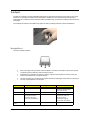
Acer Aspire 1310 Series
Service Guide
Service guide files and updates are available
on the ACER/CSD web; for more information,
please refer to http://csd.acer.com.tw
SERVICE CD PART NO.: VD.A0307.001
PRINTED IN TAIWAN
Revision History
Please refer to the table below for the updates made on Aspire 1310 service guide.
Date
II
Chapter
Updates
Copyright
Copyright © 2003 by Acer Incorporated. All rights reserved. No part of this publication may be reproduced,
transmitted, transcribed, stored in a retrieval system, or translated into any language or computer language, in
any form or by any means, electronic, mechanical, magnetic, optical, chemical, manual or otherwise, without
the prior written permission of Acer Incorporated.
Disclaimer
The information in this guide is subject to change without notice.
Acer Incorporated makes no representations or warranties, either expressed or implied, with respect to the
contents hereof and specifically disclaims any warranties of merchantability or fitness for any particular
purpose. Any Acer Incorporated software described in this manual is sold or licensed "as is". Should the
programs prove defective following their purchase, the buyer (and not Acer Incorporated, its distributor, or its
dealer) assumes the entire cost of all necessary servicing, repair, and any incidental or consequential
damages resulting from any defect in the software.
Acer is a registered trademark of Acer Corporation.
Intel is a registered trademark of Intel Corporation.
Pentium and Pentium II/III are trademarks of Intel Corporation.
Other brand and product names are trademarks and/or registered trademarks of their respective holders.
III
Conventions
The following conventions are used in this manual:
IV
SCREEN MESSAGES
Denotes actual messages that appear
on screen.
NOTE
Gives bits and pieces of additional
information related to the current
topic.
WARNING
Alerts you to any damage that might
result from doing or not doing specific
actions.
CAUTION
Gives precautionary measures to
avoid possible hardware or software
problems.
IMPORTANT
Reminds you to do specific actions
relevant to the accomplishment of
procedures.
Preface
Before using this information and the product it supports, please read the following general information.
1.
This Service Guide provides you with all technical information relating to the BASIC CONFIGURATION
decided for Acer's "global" product offering. To better fit local market requirements and enhance product
competitiveness, your regional office MAY have decided to extend the functionality of a machine (e.g.
add-on card, modem, or extra memory capability). These LOCALIZED FEATURES will NOT be covered
in this generic service guide. In such cases, please contact your regional offices or the responsible
personnel/channel to provide you with further technical details.
2.
Please note WHEN ORDERING FRU PARTS, that you should check the most up-to-date information
available on your regional web or channel. If, for whatever reason, a part number change is made, it will
not be noted in the printed Service Guide. For ACER-AUTHORIZED SERVICE PROVIDERS, your Acer
office may have a DIFFERENT part number code to those given in the FRU list of this printed Service
Guide. You MUST use the list provided by your regional Acer office to order FRU parts for repair and
service of customer machines.
V
VI
Table of Contents
Chapter 1
System Specifications
1
Features . . . . . . . . . . . . . . . . . . . . . . . . . . . . . . . . . . . . . . . . . . . . . . . . . . . . . . . .1
System Block Diagram . . . . . . . . . . . . . . . . . . . . . . . . . . . . . . . . . . . . . . . . . . . . .3
Board Layout . . . . . . . . . . . . . . . . . . . . . . . . . . . . . . . . . . . . . . . . . . . . . . . . . . . .4
Top View . . . . . . . . . . . . . . . . . . . . . . . . . . . . . . . . . . . . . . . . . . . . . . . . . . . .4
Bottom View . . . . . . . . . . . . . . . . . . . . . . . . . . . . . . . . . . . . . . . . . . . . . . . . .5
Outlook View . . . . . . . . . . . . . . . . . . . . . . . . . . . . . . . . . . . . . . . . . . . . . . . . . . . . .6
Front View . . . . . . . . . . . . . . . . . . . . . . . . . . . . . . . . . . . . . . . . . . . . . . . . . . .6
Left Panel . . . . . . . . . . . . . . . . . . . . . . . . . . . . . . . . . . . . . . . . . . . . . . . . . . .7
Right Panel . . . . . . . . . . . . . . . . . . . . . . . . . . . . . . . . . . . . . . . . . . . . . . . . . .8
Rear Panel . . . . . . . . . . . . . . . . . . . . . . . . . . . . . . . . . . . . . . . . . . . . . . . . . .9
Bottom Panel . . . . . . . . . . . . . . . . . . . . . . . . . . . . . . . . . . . . . . . . . . . . . . .10
Indicators . . . . . . . . . . . . . . . . . . . . . . . . . . . . . . . . . . . . . . . . . . . . . . . . . . . . . .11
Keyboard . . . . . . . . . . . . . . . . . . . . . . . . . . . . . . . . . . . . . . . . . . . . . . . . . . . . . .12
Special keys . . . . . . . . . . . . . . . . . . . . . . . . . . . . . . . . . . . . . . . . . . . . . . . .12
Touchpad . . . . . . . . . . . . . . . . . . . . . . . . . . . . . . . . . . . . . . . . . . . . . . . . . . . . . .15
Touchpad Basics . . . . . . . . . . . . . . . . . . . . . . . . . . . . . . . . . . . . . . . . . . . .15
Launch Keys . . . . . . . . . . . . . . . . . . . . . . . . . . . . . . . . . . . . . . . . . . . . . . . . . . . .17
Hardware Specifications and Configurations . . . . . . . . . . . . . . . . . . . . . . . . . . .18
Chapter 2
System Utilities
27
BIOS Setup Utility . . . . . . . . . . . . . . . . . . . . . . . . . . . . . . . . . . . . . . . . . . . . . . . .27
Navigating the BIOS Setup Utility . . . . . . . . . . . . . . . . . . . . . . . . . . . . . . . .27
Startup . . . . . . . . . . . . . . . . . . . . . . . . . . . . . . . . . . . . . . . . . . . . . . . . . . . .28
Exit . . . . . . . . . . . . . . . . . . . . . . . . . . . . . . . . . . . . . . . . . . . . . . . . . . . . . . .29
BIOS Flash Utility . . . . . . . . . . . . . . . . . . . . . . . . . . . . . . . . . . . . . . . . . . . . . . . .30
System Diagnostic Diskette . . . . . . . . . . . . . . . . . . . . . . . . . . . . . . . . . . . . . . . .30
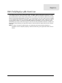
Chapter 3
Machine Disassembly and Replacement
31
General Information . . . . . . . . . . . . . . . . . . . . . . . . . . . . . . . . . . . . . . . . . . . . . .32
Before You Begin . . . . . . . . . . . . . . . . . . . . . . . . . . . . . . . . . . . . . . . . . . . .32
Disassembly Procedure Flowchart . . . . . . . . . . . . . . . . . . . . . . . . . . . . . . . . . . .33
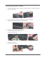
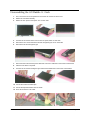
Removing the Memory/HDD Module . . . . . . . . . . . . . . . . . . . . . . . . . . . . . . . . .36
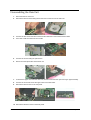
Removing the Keyboard/LCD Module . . . . . . . . . . . . . . . . . . . . . . . . . . . . . . . .37
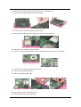
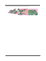
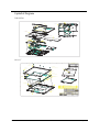
Disassembling the Main Unit . . . . . . . . . . . . . . . . . . . . . . . . . . . . . . . . . . . . . . .38
Disassembling the LCD Module-14.1 Inch . . . . . . . . . . . . . . . . . . . . . . . . . . . . .41
Disassembling the LCD Module-15.1 Inch . . . . . . . . . . . . . . . . . . . . . . . . . . . . .42
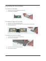
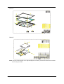
Disassembling the External Modules . . . . . . . . . . . . . . . . . . . . . . . . . . . . . . . . .43
Disassembling the HDD Module . . . . . . . . . . . . . . . . . . . . . . . . . . . . . . . . .43
Disassembling the Floppy Disk Drive Module . . . . . . . . . . . . . . . . . . . . . . .43
Disassembling the Optical Drive Module . . . . . . . . . . . . . . . . . . . . . . . . . .43
Chapter 4
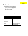
Troubleshooting
45
System Check Procedures . . . . . . . . . . . . . . . . . . . . . . . . . . . . . . . . . . . . . . . . .46
External Diskette Drive Check . . . . . . . . . . . . . . . . . . . . . . . . . . . . . . . . . .46
External CD-ROM Drive Check . . . . . . . . . . . . . . . . . . . . . . . . . . . . . . . . .46
Keyboard or Auxiliary Input Device Check . . . . . . . . . . . . . . . . . . . . . . . . .47
Memory Check . . . . . . . . . . . . . . . . . . . . . . . . . . . . . . . . . . . . . . . . . . . . . .47
Power System Check . . . . . . . . . . . . . . . . . . . . . . . . . . . . . . . . . . . . . . . . .47
Touchpad Check . . . . . . . . . . . . . . . . . . . . . . . . . . . . . . . . . . . . . . . . . . . . .48
Power-On Self-Test (POST) Error Message . . . . . . . . . . . . . . . . . . . . . . . . . . .49
Index of Error Messages . . . . . . . . . . . . . . . . . . . . . . . . . . . . . . . . . . . . . . . . . . .50
Index of Symptom-to-FRU Error Message . . . . . . . . . . . . . . . . . . . . . . . . . . . . .52
Intermittent Problems . . . . . . . . . . . . . . . . . . . . . . . . . . . . . . . . . . . . . . . . . . . . .56
VII
Table of Contents
Undetermined Problems . . . . . . . . . . . . . . . . . . . . . . . . . . . . . . . . . . . . . . . . . . .57
Chpater 5
Jumper and Connector Locations
59
Top View . . . . . . . . . . . . . . . . . . . . . . . . . . . . . . . . . . . . . . . . . . . . . . . . . . . . . . .59
Bottom View . . . . . . . . . . . . . . . . . . . . . . . . . . . . . . . . . . . . . . . . . . . . . . . . . . . .60
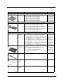
Chapter 6
FRU (Field Replaceable Unit) List
61
Aspire 1310 series . . . . . . . . . . . . . . . . . . . . . . . . . . . . . . . . . . . . . . . . . . . . . . .70
Appendix A
Model Definition and Configuration
70
Appendix B
Test Compatible Components
71
Microsoft Windows XP (Home) Environment Test . . . . . . . . . . . . . . . . . . . . . . .72
Appendix C
Index
VIII
Online Support Information
75
77
Chapter 1
System Specifications
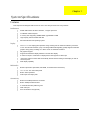
Features
This computer was designed with the user in mind. Here are just a few of its many features:
Performance
T
Moblie AMD Athlon XP1800+/ XP1900+, or higher processor
T
VIA KN266+VT8235 chipset
T
2 memory slots supporting 266MHz DDR, upgradeable to 2GB
T
High capacity, Enhanced-IDE hard disk
T
Microsoft Windows XP operating system
T
The 14.1” or 15.0” display panel provides a large viewing area for maximum efficiency and easeof-use. The thin-film transistor (TFT) Low Voltage Differential Signaling (LVDS) supports extended
graphics array (XGA), enabling 16.7 million colors at 1024X768 resolution.
T
3D graphics support.
T
Supports simultaneous display between LCD and CRT display.
T
S-video for output to a television or display device that supports S-video input.
T
“Automatic LCD dim” feature that automatically selects the best setting for the display in order to
conserve power.
T
Dual display capability
Display
Multimedia
T
Build-in optical drive (CD-ROM, DVD-ROM, or DVD/CD-RW combo drive)
T
14.1” or 15.0” TFT XGA LVDS panel
T
Built-in stereo speakers
T
Audio input and output jacks
Connectivity
Chapter 1
T
Built-in10/100 Mbps Ethernet connection
T
Built-in 56Kbps fax/data modem
T
2 universal serial bus (USB 2.0) ports
T
IEEE 1394 port
T
802.11b wireless LAN (optional)
9
Human-centric design and ergonomics
T
All-in-one design (incorporating hard drive, optical drive and floppy disk drive)
T
Rugged, yet extremely protable, construction
T
Stylish appearance
T
Full-size keyboard with 4 programmable launch keys
T
Comfortable palm rest area with well-positioned touchpad
Expansion
T
Upgradeable memory modules and hard disk
T
PC card slot enables a range of add-on options
Keyboard and Pointing Device
T
88/90key Windows keyboard
T
Ergonomically-centered touchpad pointing device
T
One type III or type II PC Card slot (PCMCIA and CardBus)
T
One IEEE 1394 port
T
One RJ-11 modem jack (V.90, 56K)
T
One RJ-45 network jack (Ethernet 10/100) mbs
T
One DC-in jack
T
One parallel port (ECP/EPP compliant)
T
One S-video TV-out port
T
One external monitor port
T
One headphone-out jack (3.5mm minijack)
T
One microphone-in jack (3.5mm minijack)
T
Two Universal Serial Bus (USB 2.0) ports
I/O Ports
10
Chapter 1
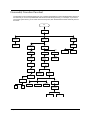
System Block Diagram
5
4
3
2
1
SYSTEM B LO C K
D IA G R A M
PCI . .CLOCK
CK-GEN
A M D Proces sor(SocketA )
DC/DC
ICS950902
P3,4
P2
M ax1632,M ax1717
P25,P24
D
CTRL
PO W ER IN
DATA
CTRL
ADDR
DATA
ADDR
TV E NCO DER
TV
P16
LCD/INV
CO NN
CD-ROM
P17
H/W
MO NITO R
200/266MHZ
2'
nd FAN
P21
P7
C
V-LINK
266MB/s
UltraDMA 100/133
PCI BUS
REQ/GNT 4
S uperSouth
VIA
P16
REQ/GNT1
VT8235
USB
CO NN
P21
T HERMA L DIODE I N
DD R
DIMM
P5,6
LVDS
P11
HDD
B att
ery
Charger
P23
DD R
DIMM
Tw ister-K
N B VT8372
S3
Savage8
P11
C
D
INTA# (VGA)
P11
CRT
19V I N
5V, 3V,CPUCORE VCC etc.
USB 2 .0
P21
INTD#
PCM CIA
O Z6912
P8,9,10
P13
AD21
REQ/GNT2
INTC,(A)#
1394
TSB43AB21
AD23
P CM C IA : I
NTD,R EQ1,G NT1,AD21
1394 : -INTC,R EQ 2,G NT2,AD23
P18
B
B
Audio
Am plifier
TPA0212
AM C97
Sm artAM C
(20468-21)
AC'97
Link
Pri mary
P12
EC/KBC
PC 87570
MO DEM DAA
R J11
P22
Sl
ot0
P13
SIO
PC 87393
P14
P14
1394
COP18
NN
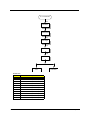
PCB Stacker:
LPT
Port P16
TOP
GND
I N1
I N2
VCC
BOT
FDD P12
P20
SM ARTDAA
(20463-11)P22
A
R J45
P18
5
Chapter 1
Touch
Pad P16
L SI
80227
Keyboar
d
P20
B IO S
0.5 oz
1 oz
1 oz
1 oz
1 oz
0.5 oz
A
FAN
P21
P20
P18
4
3
2
1
11
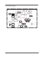
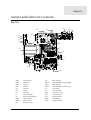
Board Layout
Top View
4
3
TX2
4
7
8
3
QD3
D23
D24
QD4
QS24
QD23
QS25
QE3
QR6
QS26
QS27
QV3
QS29
QS2:
H
QR21
QD33
QS39
QS3:
QD31
QD32
QS38
QS37
QE21
QS8
QS9
QD8
QS:
QD9
QD22 QS2
QS21 QR3
QS22 QS3
QS23 QS4
D
D
QS41
FNJ6
FNJ3
QV2
QE6
QS7
QS5
QE4 QE2
QR22
QD29
QS36
QD2:
QE:
QD2
DO3
DO2
DO4
9
D21
E7
6
S7
S9
S6
QS31
QS32
QS33
QS34
QS35
QE8
QE7
QD27
QE9
P
P
J
QD28
QS42
QM5
J
J
P
QR27
FNJ5
M7
7
2
QD26
QS28
D5
S3
M6
D4
D27
D26
D3
S2
M5
S5
TX3
D32
QS6
QR28
QD39
QS46
QR2:
QE23
QD3:
QD42
QD41
QD43
QD44
QD45
QE25
QD47
QR32
IPMF21
QS48
S45
QS53
QD49
QD52
QS54
QD53
D229
5:
59
61
58
D216
D217
28
QM21
D218
10
DPO:
59
DQ4
DQ3
D236
4
S5:
5
D243
11
QD65
D286
QD72
D328
R28
S317
E34
E36
E38
M51
M52
2
QR38
7
13
P
P
KTQLS2
FNJ27
3
D439
D438
21
E39
D437
21
2
D436
S327
S328
S332
S333
D441
S32:
S331
FNJ25
QS58
QS59
QD71
QM23
D365
D392
FNJ21
R25
S313
R27
R26
R29
P P
9: D432
D43:
99
S294
D413
SQ66
S286
SQ67
D398
SQ68
S287
S288
D399
SQ69
D424
D418
R24
H J H J H J H J H J
SQ71
56
FNJ23
D416
V24
D41:
D421
S312
E32
E35
2
2
12
S272
S293
D384
D385
D386
D387
D388
D389
D38:
D372
D371
244
243
S296
V23
QD73
55
6
S295
S298
S299
S29:
S2:1
SQ72
P
QR36
SQ57
SQ56
D39:
D393
S518
2
QS5:
QS62
2
FNJ:
SQ47
D348
D363
D362
D347
S267
QD64
QD6:
QS61
S285
V26
S329
QD69
QD66
QD67
SQ32
D285
SQ46
D346
D361
SQ54
S2:2
21
QM22
SQ45
D329
D383
D381
S268
D364
D345
D343
D382
SQ31
SQ2:
SQ29
SQ43
D342
D37:
D379
D2:9
D2:3
SQ55
S256
D2:8
D327
D341
D33:
S264
D338
S255
SQ37
KQ2
QS57
QR34
QR35
S92
S93
S94
S:6
D255
S91
S98
S99
S:7
SQ53
S265
S269
S26:
S271
SQ49
D366
D367
D359
D35:
S266
D299
SQ26
SQ27
S238
SQ42
FNJ8
IPMF24
QD63
J
H
SQ7
SQ8
D254
D2:7
D2:1
SQ3:
D394
D244
D238
S64
V6
D237
D239
D23:
D241
D242
S8:
SQ:
S96
SQ9
QD68
QD5:
QD61
55
IPMF25
DQ5
DQ2
3
M36
M37
D219
D228
S4:
S51
D21:
D221
M38
D231
M39
D232
D234
3
S55
SQ25
SQ23
SQ24
SQ38
S254
D339
M45
D272
D26:
D271
M46
D289
D28:
D295
M47
U57
D313
S281
D395
SQ62
S282
S283
SQ63
S284
D411 SQ64
S292 D396
E28
SQ65
D397
E29
D423
S315
D427
D426
S2::
S311
S314
S318
D428
D429
S2:7
D422
IPMF6
S26
QR7
H
IPMF28
FNJ28
E41
S336
S335
S334
IPMF29
FNJ24
M35
D235
21
IPMF27
FNJ26
E3:
QK2
E:
H
9
S65
D417
D419
S2:3
QR37
S326
R31
D435
R2:
DPO23
QS49
QR31
M3:
S2:8
S2:9
QD75
H
QV4
J
QR5
QM:
QS47
E24
M41
23
287
V25
R32
E37
D42:
S319
M4:
D431
S321
S324
S316
E33
QD74
QD21
35
S59
SQ6
D412
D433
S322
S323
S2:4
D425
S31:
R:
SQ74
D3:8
D3:9
S2:5
R9
D378
SQ61
S297
E31
S2:6
15
SQ5:
V22
E2:
R8
D377
D414
D3::
M49
D3:7
S28:
37
D3:5
D415
16
D36:
SQ6:
D3:4
D29:
D442 SQ73
U59
M48
D3:2
D3:1
D344
D3:3
SQ59
S27:
S261
S291
U67
SQ58
R7
E
D2:6
SQ39
D331
D336
SQ48
U6:
QM2
S25
8
S58
DPO21
D2:4
D373
D374
D375
D376
D354
S259
S276
U66
FNJ4
QR4
P
H
6
S24
S23
QS4:
QS51
QD51
22
D356
D334
U64
D34:
D351
D352
S246
D333
S247
S248
S242
D2:5
F
D357
SQ4:
S262
D358
SQ51
S263
SQ52
D32:
D332
S279
D325
D311
SQ36
QS43
DPO9
D258
S::
S216
D267
D434
S325
D291
U22
SQ22
S237
QD48
QD4:
QS52
36
D249
D24:
S7:
S89
V7
S228
S229
S232
S233
D284
E
G
M42
D251
S71
S73 S74 S75
S77 S78 S79
S82 S83 S84
S86 S87 S88
S9: D256
S:3 S:4
S:9 D261
S214 S215
S:8
S213
D265
S222
S223
V8
S22:
U51
D7:8
U4:
F
U65
U62
U61
U5:
S224
36
35 37
S97
S95
S:1
S219
D353
S275
U44
G
D293
D312
D297
U48
U45
U49
S274
D368
D369
D391
S277
U46
U47
S278
D274
S289
S25:
FNJ22
S221
U9
U8
U7
U63
S257
U53
SQ33
S243
D317
D318
D326
S23:
D337
V21
D321
D322
D323
D314
D324
S249
S24:
S251
S252
S253
D335
KTQLM2
S236
U55
U58
D31:
D296
U56
S239
3
U52
U54
D298
SQ21
36
D349
E27
S517
S258
IPMF26
S273
D355
3
S21:
U21
D2::
S241
D316
D315
SQ34
SQ35
S244
S245
DPO22
U6
D319
D282
D294
59
V9
D3:6
D278
D283
48
D275
S225
S226
S227
S231
D273
24 V:
FNJ9
17
D276 2
D27:
S234
S235
D288
D277
D259
D25:
D262
D266
QD34
,
Z3
D279
D281
D287
D292
QD62
D263
D257
R23
7
M44
D269
R22
S:2
QD58
D268
D264
S217
S218
QD59
S:5
E25
E26
S211
S212
QS55
18
D
D
2
QR9
2
QD5
QM3
QD6 E9
E8
S22
QE5
5
D22
S:
E6
S21
QD55
S69
S6:
D252
D253
S76
S81
S85
S72
M43
QR33
S56
S54
D247
D248
QD56
QD57
QV6
QS56
QR8
QM9
DO7
SQ41
D225
IPMF23
P
Z2
S57
D22:
D223
S52
D226
D222
J
H
SQ5
IPMF22
D233
B88
22 24 26
2: 32
21 23 25 27 29
31 33
34
7 8 9 :
5 6
D224
4
3
D227
FNJ76
S48
S49
M34
D212
D213
BE
BF
BG
2
FNJ77
C88
QD25
QR23
QR24
QM8
IPMF7
QM7
QR25
,
D215
BB
BC
SQ3
SQ4 BD
S42
BE
D9:
BF
D:1
D:4 BG
M31
D:7
D:9
D::
M33
D214
S61
S63
S68
S66
D246
R21
QM6
Q
S
U
V
W
X
QD54
Z
BB
BC
BD
S53
D211
M32
D:6
S46
S47
19
O
Q
S
U
V
W
X
Z
D:8
5
4
E5
QD:
QV5
M
N
O
N
D:3
QD24
5
V3
QR2 QD7
4
M2
2
D25
3
7
QS44
FNJ7
D96
S3:
I
K
L
M
M2:
SQ28
S44
D:2
D:5
D2:2
R6
S43 S41 D98
TX6
M29
B
C
D
E
F
G
H
I
K
L
SQ44
H
P
J
P
H
R5
J
D99
D95
S39
M28
B
C
D
E
F
G
H
V5
B2
2
QE22
M24
33 35 37
2 3 4 5 6 7 8 9 : 21222324 25 27 29 31
26 28 2: 32
U2
34 36
R4
DPO7
C2
TX5
3
QR:
QD38
P
S36
S37
S38
M23
D81
M22
SQ2
DPO8
E21
O
M8
H
H
QE24
D79
EBFU3ENC7F5!SFW;F
E23
E22
2
J
QR29
I9
48
D7:
N
D9
9
I
7
2
IPMF4
5
H
M
4
3
QR26
QS45
P
QD46
I:
IPMF9
E
QM4
QD37
D85
D89
M25
M26
IPMF8
4
QD36
D86
D92 D82
D88 D93M27
D83
D8:
D94 D84
D91
S33
S32
S35
M:
M21
D63
T
9
2
5
4
J
S34
35
36
37
38
39
3:
41
42
43
44
45
46
47
C
IPMF:
QD35
27
28
29
2:
31
32
33
34
D77
D74
M
3
G
L
H
3
3
D64
S31
DO6
5
4
2
F
K
D34
B
M
D
C
E
O
F
K
G
N
Q
S
I
L
R
D31
C
S2:
D38
R3
D44
D52 D49 D4:
D58 D55 D56
D6: D61 D62
D76 D67 D68
D73
21
20
B
D46
D87
DO5
D45
3
3
D33
D97
21
:
DPO6
D37
2
2
1
E
J
E3
P
J
TX4
2
5
I6
V4
2
3
4
5
6
7
8
9
:
21
22
23
24
25
D36
B
D42 D43 D39
D48 D51
D54 D57
D5: D69
D66 D75 D3:
D72
4
5
3
D41
D47
D53
D59
D65
D71
E2
D28
QTX2
I7
7
3 S8
D29
4
5
2
D:
D6
D7
D8
DPO4
BB
T
V
X
Z
[
U
W
S27
BD
S29
BF
BC
H
BK
BH
BG
BO
BN
BE
31
M4
M3
2
3
D78
4
J
BL
9
8
6
22
BI
S28
PBM
22
23
D35
M9
V2
2
D2:
N
E2
E4
S4
51
H
IPMF2
IPMF5
DPO5
R2
DPO2
J
2
SQ211
Y
IPMF3
27
D2
E3
24
36
FNJ2
1
MD
3
26
DPO3
32
SW2
23
25
P
2
6
5
P
2
14
12
1
LCD Connector
13
NS87570 Embeded Controller
2
Printer Port
14
Right Speaker Connector
3
CRT Connector
15
FDD Connector
4
USB Connector
16
Left Speaker Connector
5
1394 Connector
17
AC97 Codec smartamc cx20468-21
6
TV-Out
18
Clock generator
7
Power Jack
19
PCMCIA Connector
8
CPU Connector
20
Headphone-out Connector
9
Northbridge KN266 VT8372
21
Microphone-in Connector
10
ODD Connector
22
LAN Connector
11
HDD Connector
23
Modem Connector
12
Battery Connector
Chapter 1
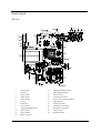
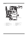
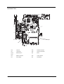
Bottom View
4
2
5
2
5
4
4
3
3
5
3
2
85RQ
912SQ
812SQ
722DQ
822DQ
:22DQ
53EQ
J
72MQ
:5JNF
532DQ
P
H
332DQ
63EQ
412SQ
232DQ
I
58SQ
48SQ
F
68SQ
2
643S
974D
543S
874D
8OD
69DQ
38SQ
JN
864D
764D
:64D
45M
664D
35M
964D
7
53JNF
56SQ
24
174D
153S
774D
253S
943S
812DQ
75RQ
65RQ
6:QS
72
82
92
:2
7:QS
13
23
33
43
53
63
432DQ
632DQ
:4
25
35 15
::2
113
3
8:QS
22OD
9:QS
::2
25
587D
:4
3
5
2
887D
987D
66JNF
487D
794S
187D
:77D
694S
D
D
46JNF
677D
::QS
877D
777D
56JNF
6
3
15
112SQ
922DQ
132DQ
212SQ
512SQ
43EQ
312SQ
5:QS
42
52
62
73
577D
477D
:8M
684S
:7DQ
44JNF
16
95
:5
85
5:6D
315S
75JNF
35
12OD
367D
:84S
667D
967D
66SQ
23EQ
33EQ
B
B
B
B
113
16JNF
657D
467D
984S
98M
267D
167D
26E
277D
377D
19M
494S
177D
36JNF
594S
:67D
75M
8:DQ
:12DQ
222DQ
712SQ
937D
85R
394S
G
G
65M
14JNF
74RQ
122DQ
322DQ
612SQ
65JNF
415S
Z
S
Q
V
U
78M
88M
16E
784S
73JNF
912DQ
35RQ
45JNF
55JNF
26S
4:QS
22
32
J
14RQ
28M
796D
134S
:24S
87JNF
8!
9!
:!
12
557D
:2JNF
59SQ
49SQ
89SQ
79SQ
69SQ
412DQ
18M
:56D
966D
596D
496D
576D
396D
296D
196D
83U
::6D
234S
334S
356D
756D
:66D
:34S
644S t
2
3
46SQ
49DQ
:8SQ
98SQ
19QS
19SQ
89DQ
72EQ
312DQ
9:DQ
112DQ
5:SQ
236D
136D
:26D
636D
536D
166D
156D
637D
4
H
4:6D
954D
854D
754D
654D
554D
454D
354D
254D
154D
:44D
944D
844D
744D
644D
544D
444D
344D
5
8Z
7!
77DQ
:3RQ
93RQ
42MQ
88DQ
8VQ
7:DQ
:16D
916D
816D
9:5D
126D
93U
426D
526D
GB
X
W
EB
DB
G
974S
947D
847D
584S
34V
457D
484S
2
874S
747D
24V
647D
357D
:47D
44V
147D
347D
547D
:74S
:3V
63JNF
2
F;WFS!5F7CNE3UFBE
FB
CB
BB
O
N
M
L
K
H
C
B
68M
257D
157D
384S
184S
284S
774S
447D
P
44R
24RQ
79DQ
2!
74
674D
36SQ
37SQ 57SQ
27SQ 47SQ
99SQ
1:SQ
84RQ
365D
76M
62MQ
3:QS
3!
4!
5!
6!
552
84
184D
:33S
374D
933S
474D
833S
274D
733S
1:DQ
39SQ
29SQ
54RQ
375D
275D
175D
:65D
86M
:86D
986D
886D
786D
686D
63U
237D
137D
89QS
99QS
:27D
737D
2KJNF
:4RQ
927D
247D
14V
563S
34R
59DQ
78SQ
88SQ
55RQ
574S
87DQ
97DQ
J
54E
254S
2:6D
977D
687D
787D
1:QS 2:QS
H
J
94RQ
512DQ
612DQ
542D
:9QS
H
2:DQ
:9DQ
82EQ
915D
335D
424S
516D
416D
316D
716D
72U
827D
337D
274S
:74D
574D
564D
464D
364D
264D
164D
:54D
28SQ
815D
56M
66M
HJ
726D
436D
146D
546D
946D
556D
956D
176D
936D
246D
746D
256D
656D
266D
387D
287D
6:4S
5:4S
4:4S
3:4S
2:4S
1:4S
:94S
994S
894S
:12
J
44RQ P
::DQ
27M
385D
17M
M
O
13JNF
18SQ
:4R
94R
265D
L
N
29DQ
28DQ
76SQ
19DQ
:8DQ
84R
74R
245D
K
E
48DQ
38DQ
68DQ
58DQ
:7SQ
97SQ
87SQ
77SQ
67SQ
18DQ
39DQ
64R
35R
34U
73U
58M
J
T
76S
H
44E
212DQ
826D
866D
766D
I
17SQ
:6SQ
:53S 35E
25E
15E
125D
295D
195D
47M
485D
314S
217D
9:6D
8:6D
7:6D
754S
9
H
243S :4E
143S 94E
84E
843S
453S
64E
33R
33JNF
384D
55E
45R
37M
1:6D
5
F
E
D
474S
374S
615S
35JNF
3
G
912
79QS
:37D
757D
2
F
864S
427D
327D
227D
537D
1
E
85JNF
48
93V
38
837D
437D
226D
4
3
3E
34RQ
:9SQ
5:DQ
92EQ
:2EQ
3:SQ 6:DQ
4:SQ 13EQ
52MQ
D
D
:64S
174S
727D
674S
666D
417D
317D
:17D
364S
83V
2
9
M
764S
964S
627D
95JNF
264S
215S
2OS
:5E
25JNF
15JNF
464S
664S
857D
957D :57D
567D 127D
564S
767D 867D 884S
194S GG
294S
527D
2E
5
3
7
4:DQ
:VQ
J
97JNF
6:6D
117D
454S
354S
59QS
164S
917D
69QS
73V
2
566D
:4JNF
75E
65E
154S
49QS
717D
617D
73 63
N
63V
P
34E
5
3MND
696D
896D
:96D
443S P
P
4
5
:43S
744S
3XTQ
H
H
622DQ
554S
854S
517D
817D
:54S
95E
366D
186D
996D
:44S
::SQ
112
626D
336D
:36D
14U
:3U
62EQ
4 3
2
712DQ
9:SQ
85E
F
F
53V
21
P
326D
346D
846D
456D
376D
856D
23V
78DQ
2
H
616D
57
476D
466D
934S
33U
45RQ
3:6D
654S
P
124S
224S
95
:5
82
72
38M
:76D
444S
344S
244S
144S
844S
944S
78
895D
2:5D
1:5D
:95D
995D
57M
65R
734S
926D
386D
486D
586D
876D
976D
43V
68
64RQ
216D
:7M
836D
446D
:46D
434S
634S
276D
94JNF
92U
48M
F
F
43U
26
16
954S
7
624S
33V
84JNF
23U
15RQ
:2U
13U
8:SQ
25RQ
7:SQ
8
57
67
86SQ
2MND
3
463S
2:SQ
:45D 155D RR
:55D 165D
214S
55R
H
J
44
34
97M
24U
t
8:
7:
6Z
J
67DQ
96SQ
763S
373S 863S
673S 573S
Q
Q
425D 225D 325D 525D
135D 925D :25D 235D
:35D 145D
835D 935D 745D 945D
845D 645D 755D 955D
855D 655D
77M
8:5D
724S
116D
125S
915S
525S
625S
75R
495D
67M
814S
795D
714S
695D
614S
514S
414S
::5D
185D 7:3S
:75D 6:3S
975D 885D
5:3S
4:3S
3:3S
2:3S
6:SQ
422DQ
E
E
595D
3:5D
4:5D
7:5D
324S
824S
924S
34
44
932
715D
3:DQ
15R 25R
J
J
:14S
914S
87M
5:5D
524S
736D
646D
534S
834S
544S
:93S 1:3S
9:3S ::3S
:OD
114S
395D JJ
7Z
2UC
7
965D
7
64JNF
7:4D
8:4D
9:4D
115D
K
K
:85D
3K
2
285D
985D
5Z
6:5D
883S
783S
683S
583S
635D
54JNF
L
L
34
:5
425S
225S
725S
325S
:15S
R
R
P
J H
9VQ
I
I
585D
8:3S
785D
4
52
522DQ
555D
865D
575D
96M
765D
593S
493S
993S
685D
74JNF
9
72
57
K
K
5
10
693S
:6M
875D
4Z
98DQ
99DQ
893S
13V
F
:8QS
255D
665D
34
JN
2
283S
355D
39QS
:2V
675D
H
P
92V
393S
775D
J
:83S
345D
293S
455D
475D
793S
363S
565D
29QS
I
I
:3JNF
465D
24R
753S
625D
383S
183S
435D
735D
983S
193S
1
98QS
93JNF
L
L
P
H
P
43R
J
53RH
H
J
743S
74E
93R :3R
83R
7VQ
P
73R
Q
Q
973S
:73S
483S
46M
82V
215D
473S
773S
873S
::4D
535D
:5M
5:4D
3:4D
953S
853S
994D
663S
45E
83JNF
P
J
653S
54R
S
S
C
C
52U
P
H H
J
72V
G
G
88QS 263S
:15D
963S
794D
1:4D
78QS
J
H
63R
G
G
194D
553S
6:4D
P
68QS
163S
615D
:63S
515D
2K
E
E
58QS
:84D
48QS
494D
394D
294D
4:4D
38QS
315D 415D
173S 273S
725D 825D
445D 545D
S
S
353S
894D
2:4D
3
14R
:7QS
584D
884D
484D
694D
28QS
18QS
984D
55M
C
C
24E
87QS
57QS
284D
:94D 16M
36M
26M
2
67QS
43JNF
784D
343S
594D
97QS
684D
92JNF
23JNF
H
H
77QS
8:4S
53U
7:4S
:87D
297D
9:4S
197D
6
9
63
::4S
54V
597D
5K
2
:
4K
86JNF
497D
53
82
72
29M
397D
39M
2:7D
34
3
:97D
6:7D
897D
832DQ
22VQ
5
4
3
96JNF
242DQ
442DQ
17JNF
311.47513DNB
732DQ
12VQ
:6JNF
9
7:7D
64V
6
932DQ
3WS
2
4:7D
3:7D
9Z
5:7D
5
115S
1:7D
27JNF
4
9
697D
95R
5
797D
997D
342DQ
142DQ
:32DQ
47JNF
37JNF
57JNF
1
LAN Controller L80227
6
PCMCIA Cardbus Controller oz6912T
2
S-Video TV-out Controller ch7011a-t
7
SIO Controller PC87393
3
RAM Connector
8
BIOS EEPROM
4
Modem Controller smartdaa 20463-11
9
IEEE 1394 TSR43AB21 Controller
5
Southbridge VT8235
10
RTC Battery
Chapter 1
13
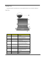
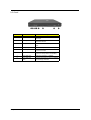
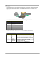
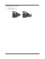
Outlook View
A general introduction of ports allow you to connect peripheral devices, as you would with a desktop PC.
Front View
#
14
Item
Description
1
Display
Large liquid crystal display (LCD) provides
visual output.
2
Launch keys
4 buttons that can be programmed to start
frequently used applications.
3
Power button
Turns the computer on and off.
4
Touchpad
Touch sensitive pad that functions like a
computer mouse.
5
Click buttons & scroll
key
Right and left buttons that provide the
same functions as the buttons on a
computer mouse. The scroll key scrolls the
contents of a window up and down.
6
Speakers
Left and right speakers deliver stereo audio
output.
7
Palm rest
Provides a comfortable platform for your
hands when typing on the keyboard.
8
Keyboard
Full-size keyboard for inputting typed data.
9
Status indicators
Light emitting diodes (LED) that show the
status of the computer and its
componenets.
10
Latch
Locks and releases the lid.
11
Wireless
communication button
Lights when the Wireless LAN capability is
enabled.
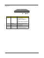
Chapter 1
Left Panel
#
Chapter 1
Item
Description
1
Modem jack
Connects the built-in fax/data modem to a
phone line.
2
Network jack
Connects the computer to an Ethernet 10/
100-based network.
3
Microphone-in jack
Connects an external microphone for audio
input.
4
Headphone jack
Connects headphones for audio output.
5
PC card eject button
Press the eject button to remove a PC card
for the PC card slot.
6
PC card slot
The slot supports a standard Type II or
Type III PC card (PCMCIA or CardBus).
7
Floppy disk drive
Supports a standard 3.5” diskette.
8
Floppy disk eject
button
Press the eject button to remove a diskette
from the floppy disk drive.
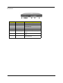
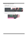
15
Right Panel
#
1
Item
Optical drive
Description
Depending on your model, the optical drive
is one of the following:
CD-ROM drive for reading CDs.
DVD-ROM drive for reading CDs and
DVDs.
DVD/CD-RW combo drive for reading CDs
and DVDs, and writing to CD-Rs and CDRWs.
16
2
Optical drive
emergency eject hole
Used to eject an optical disc when the
computer is turned off.
3
Optical drive eject
button
Press the eject button to remove a disc
from the optical drive.
4
Optical disc read
indicator
Light emitting diode (LED) that indicates
when an optical disc is being read.
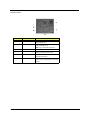
Chapter 1
Rear Panel
#
Chapter 1
Item
Description
1
Kensington lock slot
For attaching a security connector.
2
DC-in jack
Connects the AC adapter.
3
S-video
Connects to a television or display device
with S-video input.
4
IEEE 1394 port
Connects IEEE 1394 devices.
5
USB ports
2 ports for connecting USB devices.
6
External display port
Connects an external (VGA) display
monitor.
7
Parallel port
Connects a parallel device, such as a
printer.
8
Ventilation slots
Enable the computer to stay cool. even
after prolonged use.
17
Bottom Panel
#
Item
Description
1
Ventilation slots
Enables the computer to stay cool, even
after prolonged use.
2
Reset Switch
Forces the computer to shut down in the
event of system lockup.
Note: Any unsaved data will be lost.
18
3
Battery
The computer’s removable battery.
4
Battery release latch
Slide and hold the latch, and then pull the
battery to remove it from the unit.
5
Hard disk bay
Removable cover provides access to the
computer’s hard drive.
6
Memory compartment
Removable cover provides access to the
memory slots for upgrading the computer’s
memory.
Chapter 1
Indicators
Your computer provides an array of six indicators located above the keyboard, in addition to two indicators
positioned at the from of the palm rest area. These indicators show the status of the computer and its
components.
The six indicators located above the keyboard provide the following status information:.
#
Description
1
Caps Lock active
2
Num Lock active (Note: the keypad lock
must be turned on to use the embedded
numeric keypad.)
3
Scroll Lock active
4
Floppy disk drive activity
5
Hard disk drive activity
6
Optical drive activity
The two indicators located at the front of the unit provide the following status information:
#
1
2
Chapter 1
Battery charge:
Green
the AC adapter is connected and the battery is fully charged.
Amber
the AC adapter is connected and the battery is charging.
Red
the AC adapter is connected and the battery has a fault.
Off
the AC adapter is not connected, or the battery is not installed.
Power mode:
Steady green
the computer is on (even if the display is turned off).
Flashing green
the computer is in standby mode.
Off
the computer is turned off, or in hibernation mode.
19
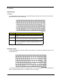
Keyboard
Special keys
Lock keys
The keyboard features full-size keys with an embedded keypad, separate cursor control keys, two Windows
keys, and twelve function keys (hot keys).
Lock Key
Description
Caps Lock
When Caps Lock is on, all alphabetic characters are typed in uppercase.
Toggle on and off by pressing the Caps Lock key on the left side of the
keyboard.
Num lock
When Num Lock is on, the embedded numeric keyboard can be used.
Toggle on and off by pressing the Fn+tkeys simultaneously.
Scroll lock
When Scroll Lock is on, the screen toggles up or down one line at a time
when the up and down cursor control keys are pressed. Note: Scroll Lock
doesn’t work in all applications. Toggle on and off by pressing the Fn +u
keys simultaneously.
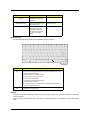
Embedded Keypad
The embedded keypad functions like a desktop numeric keypad. It is indicated by small blue numbers and on
the applicable keys.
To use the the embedded numeric keys, toggle the Num Lock on by pressing the Fn + t keys simultaneously.
With the embedded keypad turned on, the following actions are possible:
20
Chapter 1
Desired Access
Number keys on embedded
keypad
Num Lock On
Num Lock On
Type numbers using
embedded keypad in the
normal way.
Cursor-control keys on
embedded keypad
Hold down the jkey while
using the cursor keys on the
embedded keypad.
Hold Fn key while using
cursor-control keys.
Main keyboard keys
Hold down the Fn key while
typing letters using the
embedded keypad keys.
Simultaneously press the
j key for for capital
letters.
Type letters in the normal
way.
Windows Keys
The keyboard has two keys that perform Windows-specific functions.
Key
Description
Windows logo
key
Pressed alone, this key has the same effect as clicking on the Windows
Start button; it launches the Start menu. It can also be used with other keys
to provide a variety of functions:
+ Tab (Activates the next Taskbar button)
+ E (Opens the My Computer window)
+ F1 (opens Help and Support)
+ F (opens the Find: All Files dialog box)
+ M (minimizes all windows)
j + Windows logo key + M (undoes the minimize all windows action)
+ R (opens the Run dialog box)
Application
key
This key has the same effect as clicking the right mouse button; it opens
the application’s context menu.
Hotkeys
Using the Fn key with another key creates a hot key, providing a quick and convenient method for controlling
various functions.
To use a hot key, first hold down the Fn key. Next, press the second key in combination. Finally, release both
keys.
Chapter 1
21
Hot Key
Function
Fn + l
Decreases the display panel brightness.
Fn + m
Increases the display panel brightness.
Fn + p
Toggles the display setting between (1) the computer’s LCD panel, (2) an external
display device connected to the external display port, and (3) simultaneous display
on the computer’s LCD panle and an external display device.
Fn + t
Toggles Num Lock on and off. (Please see “Special keys”.)
Fn + u
Toggles the keyboard’s Scroll Lock on and off. (Please see “Special keys”.)
Fn +g
Toggle the sound on and off. (Mute.)
Fn +{
Increases the sound volume. (Doesn’t work for an external keyboard.)
Fn +}
Decreases the sound volume. (Doesn’t work for an external keyboard.)
NOTE: When activating hotkeys, press and hold the Fn key before pressing the other key in the hotkey
combination.
Euro key
Your computer supports the new Euro currency character. First, hold down the Alt Gr key, and then press the
Euro key.
Keyboard Ergonomics
The wide palm rest area provides a comfortable platform for your hands when typing on the keyboard. The
ergonomic design enables you to adopt a relaxed, yet very efficient, typing style.
22
Chapter 1
Touchpad
The built-in touchpad is a PS/2-compatible pointing device that senses movement on its surface. This cursor
responds to your finger movements on the touchpad. In addition, the two click buttons provide the same
functionality as a computer mouse, while the scroll key enables easy up and down scrolling in documents and
web pages.
The touchpad is located in the middle of the palm rest area, providing maximum comfort and efficiency.
Touchpad Basics
Use the touchpad as follows:
T
Slide your finger over the surface of the touchpad to control the movement of the cursor. Tap the
touchpad to perform selection and execution functions.
T
Press the left (1) and right (3) buttons to perform selection and execution functions, just as you
would use the buttons on a computer mouse.
T
Use the scroll key (2) to scroll through long documents and web pages. Press the top of the key to
scroll up, and the bottom to scroll down.
Function
Left Button
Righ Button
Tap
Execute
Click twice quickly
Select
Click once
Tap once
Drag
Click and hold. Then slide
your finger across the
touchpad to drag the
cursor over the selection.
Tap twice quickly. On the
second tap, slide your
finger across the
touchpad to drag the
cursor over the selection.
Access context
menu
Chapter 1
Tap twice (at the same
speed as double-clicking
the mouse button)
Click once
23
NOTE: Keep your fingers, as well as the surface of the touchpad dry and clean. The touchpad is sensitive to
your finger movements: the lighter the touch, the better the response. Tapping hard will not increase the
touchpad’s responsiveness.
24
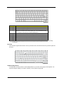
Chapter 1
Launch Keys
Located at the top of the keyboard are four buttons. These buttons are called launch keys. They are
designated as key 1, key 2, key 3 and key 4. By default, key 1 is used to launch the email application and key
2 is used to launch the Internet browser. Keys 3 and 4 start the Launch Manager application. All four launch
keys can be set by the user.
To see the launch keys, run the Acer Launch Manger.
#
Description
Email
Launches your email application.
Web browser
Launches your Internet browser
P1
User-programmable
P2
User-programmable
Chapter 1
25
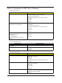
Hardware Specifications and Configurations
Processor
Item
Specification
CPU type
AMD Athlon XP (1.2G-1.8G) FSB200/266M
CPU package
OPGA
CPU core voltage
1.75V/1.45V
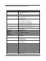
BIOS
Item
Specification
BIOS vendor
Phoenix
BIOS Version
1.0
BIOS ROM type
Flash ROM
BIOS ROM size
512KB
BIOS package
TSOP
Supported protocols
ACPI 1.0b,APM 1.2, PC Card 95, SM BIOS 2.3, EPP/IEEE 1284, ECP/
IEEE 1284 1.7 & 1.9, PCI 2.2, PnP 1.0a, DMI 2.0, USB, VESA VGA BIOS,
DDC-2B, CD-ROM bootable, Windows keyboard Microsoft Simple Boot
Flag
BIOS password control
Set by setup manual
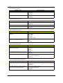
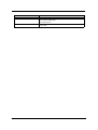
Second Level Cache
Item
Specification
Cache controller
Built-in CPU
Cache size
256KB
1st level cache control
Always enabled
2st level cache control
Always enabled
Cache scheme control
Fixed in write-back
System Memory
Item
Specification
Memory controller
26
Onboard memory size
0MB
DIMM socket number
2 sockets (4 banks)
Supports memory size per socket
1024MB
Supports maximum memory size
2GB
Supports DIMM type
DDR-SDRM(Double Data Rate-Synchronous Dynamic Random Access
Memory)
Supports DIMM Speed
266 MHz
Supports DIMM voltage
3.3V
Supports DIMM package
200-pin soDIMM
Memory module combinations
You can install memory modules in any combinations as long as they
match the above specifications.
Chapter 1
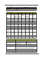
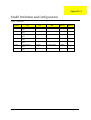
Memory Combinations
Slot 1
Slot 2
Total Memory
0MB
64MB
64 MB
64MB
0MB
64 MB
0MB
128MB
128 MB
64MB
64MB
128 MB
128MB
0MB
128 MB
64MB
128MB
192MB
128MB
64MB
192MB
128MB
128MB
256MB
256MB
64MB
320MB
64MB
256MB
320MB
256MB
128MB
384MB
128MB
256MB
384MB
256MB
256MB
512MB
512MB
512MB
1024MB
512MB
0MB
512MB
0MB
512MB
512MB
Above table lists some system memory configurations. You may combine DIMMs with various capacities to
form other combinations..
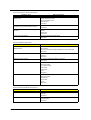
LAN Interface
Item
Specification
Chipset
VIA LAN controller
Supports LAN protocol
10/100 Mbps
LAN connector type
RJ45
LAN connector location
Left side
Modem Interface
Item
Specification
Chipset
CONEXANT soft modem (on board) 20463-11
Fax modem data baud rate (bps)
14.4K
Data modem data baud rate (bps)
56K
Supports modem protocol
V.90 MDC
Modem connector type
RJ11
Modem connector location
Left side
Floppy Disk Drive Interface
Item
Vendor & model name
Specification
Panasonic JU-226A 243FC
Floppy Disk Specifications
Media recognition
2DD (720KB)
2HD (1.2MB, 3-mode)
2HD (1.44MB)
Sectors/track
9
15
18
Tracks
80
80
80
Rotational speed (RPM)
300
360
300
Read/write heads
2
Encoding method
MFM/FM
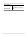
Chapter 1
27
Floppy Disk Drive Interface
Item
Specification
Power Requirement
Input Voltage (V)
+5V +/- 10%
Hard Disk Drive Interface
Item
Specification
Vendor &
Model Name
TOSHIBA
20G(MK20
18GAP),
TITAN
IBM
20G(IC25N
020ATCS0
4-0),
07N8325,
CASCADE
IBM
30G(IC25N
030ATCS0
4-0),
07N8326,
CASCADE
TOSHIBA
30GB(MK3
021GAS)
NEPTUNE
HGST
40GB
(IC25N040
ATCS04-0
07N8327)
CASCADE
TOSHIBA
40GB(MK4
021GAS)
NEPTUNE
TOSHIBA
60GB(MK6
021GAS)
NEPTUNE
Capacity
(MB)
20000
20000
30000
30000
40000
40000
60000
Bytes per
sector
512
512
Data heads
2
3
4
4
Disks
1
2
2
2
Spindle
speed (RPM)
4200 RPM
4200 RPM
4200RPM
4200RPM
4200RPM
4200RPM
4200RPM
2048KB
2048KB
2048KB
2048KB
2048KB
2048KB
ATA-5
ATA-5
ATA-5
ATA-5
ATA-5
Drive Format
Performance Specifications
Buffer size
2048KB
Interface
ATA-5
ATA-5
Max. media
transfer rate
(disk-buffer,
Mbytes/s)
216
216
Data transfer
rate
(host~buffer,
Mbytes/s)
100 MB/
Sec.
100 MB/
Sec.
100 MB/
Sec.
100 MB/
Sec.
100 MB/
Sec.
100 MB/
Sec.
100 MB/
Sec.
Ultra DMA
mode-5
Ultra DMA
mode-5
Ultra DMA
mode-5
Ultra DMA
mode-5
Ultra DMA
mode-5
Ultra DMA
mode-5
Ultra DMA
mode-5
5V(DC) +/5%
5V(DC) +/5%
5V(DC) +/5%
5V(DC) +/5%
5V(DC) +/5%
5V(DC) +/5%
DC Power Requirements
Voltage
tolerance
5V(DC) +/5%
DVD-ROM Interface
Item
Specification
Vendor & model name
DVD-ROM 8X QSI SDR-083
Performance Specification
With CD Diskette
With DVD Diskette
Transfer rate (KB/sec)
Sustained:
Sustained:
Max 3.6Mbytes/sec
Max 10.8Mbytes/sec
Data Buffer Capacity
128 KBytes
Interface
IDE/ATAPI
Applicable disc format
DVD: DVD-5, DVD-9, DVD-10, DVD-R (3.95G)
CD: CD-Audio, CD-ROM (mode1 and mode 2), CD-ROM XA(mode 2 form 1
and form 2), CD-I (mode 2, form 1 and form 2), CD-I Ready, CD-I Bridge CDWO, CD-RW, Photo CD, Video CD, Enhanced Music CD, CD-TEXT
Loading mechanism
Soft eject (with emergency eject hole)
Power Requirement
Input Voltage
28
+5 V +/- 5 %
Chapter 1
Audio Interface
Item
Specification
Audio Controller
Conexant CX 20468-21
Audio onboard or optional
Built-in
Mono or Stereo
Stereo
Resolution
20 bit stereo Digital to analog converter
18 bit stereo Analog to Ditial converter
Compatibility
Microsoft PC98/PC99, AC97 2.1
Mixed sound source
Line-in, CD, Video, AUX
Voice channel
8/16-bit, mono/stereo
Sampling rate
44.1 KHz
Internal microphone
No
Internal speaker / Quantity
Yes
Supports PnP DMA channel
DMA channel 0
DMA channel 1
Supports PnP IRQ
IRQ3, IRQ5, IRQ7, IRQ9, IRQ10, IRQ11
Video Interface
Item
Specification
Chip vendor
VIA
Chip name
S3 Savage 4 integrated in VT8235
Supports ZV (Zoomed Video) port
No
Graph interface
4X AGP (Accelerated Graphics Port) bus
Maximum resolution (LCD)
1024X768
Maximum resolution (CRT)
1024X768
Video Memory
ItemResolution
Specification
Fixed or upgradeable
Fixed
Video memory size
32MB/
Parallel Port
Item
Specification
Parallel port controller
VIA VT8235
Number of parallel port
1
Location
Rear side
Connector type
25-pin D-type connector, in female type
Parallel port function control
Enable/Disable by BIOS Setup
Supports ECP/EPP/Bi-directional (PS/2
compatible)
Yes (set by BIOS setup)
Optional ECP DMA channel (in BIOS Setup)
DMA channel 1 and 3
Optional parallel port I/O address (in BIOS
Setup)
3BCh, 278h, 378h
Optional parallel port IRQ (in BIOS Setup)
IRQ7, IRQ5
Chapter 1
29
USB Port
Item
Specification
USB Compliancy Level
1.1
OHCI
USB 2.0
Number of USB port
2
Location
Rear panel
Serial port function control
Enable/Disable by BIOS Setup
PCMCIA Port
Item
Specification
PCMCIA controller
OZ 6912
Supports card type
Type-III/II
Number of slots
One type-III
Access location
Left side
Supports ZV (Zoomed Video) port
No ZV support
Supports 32 bit CardBus
Yes (IRQ11)
System Board Major Chips
Item
Controller
System core logic
VIA KN266(Twist-K)+VT8235
Super I/O controller
NS PC87393
Audio controller
CONEXANT CX20468-21
Video controller
VIA Twist-K internal S3 Graphics
Hard disk drive controller
VT8235
Keyboard controller
PC87570
RTC
VIA KN266(Twist-K)+VT8235
Keyboard
Item
Specification
Keyboard controller
PC87570
Keyboard vendor & model name
NS
Total number of keypads
88/90-key
Windows keys
Yes
Internal & external keyboard work simultaneously
Yes
Battery
Item
30
Specification
Vendor & model name
Sanyo/Panasonic
Battery Type
Li-ion
Pack capacity
4000mAH
Cell voltage
V/cell
Number of battery cell
8
Package configuration
2 cells in series, 4 series in parallel
Chapter 1
Battery
Item
Specification
Package voltage
Li-ion 14.8V/ Ni-MH 9.6V
DC-AC LCD inverter
Item
Specification
Vendor & model
name
Quanta 3HYA1 IV0008
Input voltage (V)
8(min.)
-
20(max.)
Input current (mA)
-
-
520(max.)
Output voltage
(Vrms, no load)
-
660(typ.)
-
Output voltage
frequency (kHz)
52(min.)
58(typ.)
64(max.)
Output Current/Lamp
lout(Min.)
2.5mA/2.8mA
Vadj=0V
lout(Max.)
6.3mA/6.9mA
Vadj=3.2V
NOTE: DC-AC inverter is used to generate very high AC voltage, the support to LCD CCFT backlight user,
and is also responsible for the control of LCD brightness. Avoid touching the DC-AC inverter area while
the system is turned on.
LCD
Item
Specification
Vendor & model
name
QDI QD141X1LH03
LG LP150X2-A2M1/LP150X2-A296
Samsung LTN141X8L04
Sharp LP150X1 LH82
AU B141XN04
AU B150XN01
Mechanical Specifications
LCD display area
(diagonal, inch)
14.1
15.0
Display technology
TFT
TFT
Resolution
XGA (1024X768)
XGA (1024x768)
Supports colors
262K
262K
Brightness control
keyboard hotkey
keyboard hotkey
Contrast control
No
No
Suspend/Standby
control
Yes
Yes
Supply voltage for
LCD display (V)
3.3
3.3
Supply voltage for
LCD backlight
(Vrms)
690
690
Optical
Specification
Electrical
Specification
AC Adapter
Item
Vendor & model name
Specification
Delta 75W ADP-75FB B(WPFC) 3P
Lite-on 75W PA 1750-02Z(WPFC) 3P
Input Requirements
Chapter 1
31
AC Adapter
Item
Specification
Maximum input current (A,
@90Vac, full load)
2.25A
@ 90Vac
Nominal frequency (Hz)
47 - 63
Frequency variation range (Hz)
47 - 63
Nominal voltages (Vrms)
100- 240
Inrush current
The maximum inrush current will be less than 50A and 100A when the adapter
is connected to 115Vac(60Hz) and 230Vac(50Hz) respectively.
Efficiency
It should provide an efficiency of 83% minimum, when measured at maximum
load under 115V(60Hz).
1.125A
@ 180Vac
Output Ratings
DC output voltage
+18.8V~20.0V including the effects of line voltage variation, load current,
ripple and noise
Noise + Ripple
400mvp-p (20MHz bandwidth) for resistor load
Output current
0~4A
Input rated voltage
100/240V
Input current
2.25A@90Vac for Delta/ 1.125@180Vac for Lite-On
Dynamic Output Characteristics
Turn-on delay time
3 sec.
Hold up time
4 ms min. (115 Vac, input full load)
Over Voltage Protection (OVP)
29 V
Short circuit protection
Output can be shorted without damage
Electrostatic discharge (ESD)
15kV (at air discharge)
8kV (at contact discharge)
Dielectric Withstand Voltage
Primary to secondary
3000Vac (4242Vdc) 10mA for 1 second
Leakage current
100uA max (240Vac, 60Hz)
Regulatory Requirements
Internal filter meets;
1. FCC class B requirements.
2. VDE 243/1991 class B requirements.
3. CISPR 22 Class B requirements.
3. VCCI class II requirements.
Power Management
Power Saving Mode
Standby Mode
Phenomenon
The Sleep indicator lights up
Waiting time specified by the System Standby value
or the operating system elapses without any system
activity.
Or
When the computer is about to enter Hibernation
mode (e.g. during a battery-low condition), but the
Hibernation file is invalid or not present.
Hibernation Mode
All power shuts off
When customized functions for power management
are set to Hibernation and the corresponding action is
taken.
Display Standby Mode
The display shuts off
Keyboard, built-in touchpad, and an external PS/2
pointing device are idle for a specified period.
32
Chapter 1
Power Management
Power Saving Mode
Phenomenon
Hard Disk Standby Mode
Hard disk drive is in standby mode. (spindle turned-off)
Hard disk is idle within a specified period of time
Environmental Requirements
Item
Specification
Temperature
Operating
0~+40 °C
Non-operating
-20~+60 °C (unpacked)
Non-operating
Non (storage package)
Humidity
Operating
0% to 90% RH, non-condensing
Non-operating
20% to 90% RH, non-condensing (unpacked)
Non-operating
Non (storage package)
Vibration
Operating (unpacked)
5~500Hz: 1.0Grms (random)
Non-operating (unpacked)
5~500Hz: 2.16Grms (random)
Non-operating (packed)
5~500Hz: 2.16Grms (random)
Mechanical Specification
Item
Specification
Dimensions
319mm (W) x 260mm (D) x 33mm (H) for 14.1 inch model
Weight
2.9Kg (6.4 lbs) for 14.1 inch model; 3.1KG (6.8 lbs) for 15.0 inch model
I/O Ports
2 USB port, 1VGA (external monitor) port, 1 Microphone in jack, 1 Headphone
out jack, 1 RJ-11 jack for modem, 1 RJ-45 jack for Ethernet, 1 PCMCIA (Type II
or Type III) slot, 1 Parallel port (ECP/EPP compliant), 1DC-in jack for AC
adapter, 1 S-video port, 1 IEEE1394 port
Drive Bays
One
Material
Plastic
Indicators
Power Mode LED, Battery Charge, Caps Lock, Num Lock, Scroll Lock, FDD
activity, HDD activity, ODD activity
Switch
Power
330mm (W) x 267mm (D) x 35mm (H) for 15.0 inch model
Memory Address Map
Memory Address
00100000h-000F0000h
Size
Function
512 KB
System BIOS
000CD000h-000C0000h
VGA BIOS
000C0000h-000A0000h
128 KB
Video memory (VRAM)
000A0000h-00000000h
640KB
Conventional memory
I/O Address Map
I/O Address
Function
000-00F
DMA controller-1
020-021
Interrupt controller-1
040-043
Timer 1
060, 064
Keyboard controller 87570 chip select
061
System speaker
Chapter 1
33
I/O Address Map
I/O Address
Function
040B
DMA controller-1
061
System speaker
070-073
Real-time clock and NMI mask
080-08F
DMA page register
0A0-0A1
Interrupt controller-2
0C0-0DF
DMA controller-2
0F0-0FF
Numeric data processor
66, 62
Power management controller
170-177
2nd EIDE device (CD-ROM) select
1F0-1F7
1st EIDE device (hard drive) select
378, 37F
Parallel port 1
3B0-3BB
Video Controller
3C0-3DF
3F0h-3F7
Standard Floppy Disk Controller
3F0-3F7
Floppy disk controller
480-48F, 4D6
DMA controller-1
CF8-CFF
PCI configuration register
IRQ Assignment Map
Interrupt Channel
Function(Hardware)
IRQ00
System timer
IRQ01
Keyboard
IRQ06
Floppy
IRQ08
CMOS/RTC
IRQ09
SCI IRQ used by ACPI bus
IRQ10
Audio, Modem,
IRQ11
USB, CardBus controller, LAN
IRQ12
Alps pointing device
IRQ13
Numeric data processor
IRQ14
1st EIDE device (hard disk)
IRQ15
2nd EIDE device (CD-ROM drive)
DMA Channel Assignment
DMA Channel
DRQ0
34
Function(Hardware)
Reserved
DRQ1
Reserved
DRQ2
Floppy
DRQ3
ECP printer port (LPT1)
DRQ4
DMA controller
DRQ5
Reserved
DRQ6
Reserved
DRQ7
Reserved
Chapter 1
Chapter 2
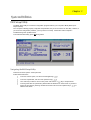
System Utilities
BIOS Setup Utility
The BIOS Setup Utility is a hardware configuration program built into your computer’s BIOS (Basic Input/
Output System).
Your computer is already properly configured and optimized, and you do not need to run this utility. However, if
you encounter configuration problems, you may need to run Setup. Please also refer to Chapter 4
Troubleshooting when problem arises.
To activate the BIOS Utility, press m during POST.
Navigating the BIOS Setup Utility
There are two menu options: Startup and Exit
Follow these instructions:
Chapter 2
T
To choose a menu option, use the cursor left/right keys (zx).
T
To choose a parameter, use the cursor up/down keys ( wy).
T
Use <Tab> key to select a control. Then press <OK> button or e key to accept entries.
T
To change the value of a parameter, please follow the directions on each screen. If you like to
assign the boot device, please go to Boot Device then use the cursor up/down keys ( wy) to
select a boot device.
37
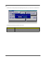
Startup
The Startup screen displays a summary of your computer hardware information, and also includes basic setup
parameters. After you enter BIOS, you will first see the system information on the first page, then you can use
the cursor up/down keys ( wy) to select the parameter you like to change.
NOTE: The screen above is for reference only. Actual values may differ.
.
Parameter
Description
Date and Time
Sets the system date and time. Please use <Tab> key going to the item you like to change.
Boot Device
Sets the boot device of the system.
The items in this screen are important and vital information about your computer. If you experience computer
problems and need to contact technical support, this data helps our service personnel know more about your
computer.
38
Chapter 2
Exit
The Exit screen contains parameters that help safeguard and protect your computer from unauthorized use.
The table below describes the parameters in this screen.
Parameter
Description
Save and Exit
Saves changes made and reboot the system.
Exit (No Save)
Discards changes made and exits the BIOS Setup Utility.
Default Settings
Loads default settings for all parameters.
Chapter 2
39
BIOS Flash Utility
The BIOS flash memory update is required for the following conditions:
T
New versions of system programs
T
New features or options
T
Restore a BIOS when it becomes corrupted.
Use the Flash utility to update the system BIOS flash ROM.
NOTE: If you do not have a crisis recovery diskette at hand, then you should create a Crisis Recovery
Diskette before you use the Flash utility.
NOTE: Do not install memory-related drivers (XMS, EMS, DPMI) when you use the Flash.
NOTE: Please use the AC adaptor power supply when you run the Flash utility. If the battery pack does not
contain enough power to finish BIOS flash, you may not boot the system because the BIOS is not
completely loaded.
Fellow the steps below to run Flash utility.
1.
Prepare a bootable diskette.
2.
Copy the Flash utilities to the bootable diskette.
3.
Then boot the system from the bootable diskette. The Flash utility has auto-execution function.
System Diagnostic Diskette
IMPORTANT: 1The diagnostics program we use for Aspire 1310 is not exactly the same as PQA (Product
Quality Assurance), the diagnostic program we used to employ in other model. The system
diagnostic utilities is provided by Acer Headquarters. You can utilize it as a basic diagnostic tool. To
get this program, find it on CSD website. To better fit local service requirements, your regional office
MAY have other diagnostic program. Please contact your regional offices or the responsible
personnel/channel to provide you with further technical details. The diagnostic program contains a
readme file. Please read the readme file as you run the diagnostic program.
1
40
New added description. Please pay attention to it.
Chapter 2
Chapter 3
Machine Disassembly and Replacement
This chapter contains step-by-step procedures on how to disassemble the notebook computer for
maintenance and troubleshooting.
To disassemble the computer, you need the following tools:
T
Wrist grounding strap and conductive mat for preventing electrostatic discharge
T
small Philips screwdriver
T
flat head screwdriver
T
Philiips screwdriver
T
nut screwdriver
tweezers
NOTE: The screws for the different components vary in size. During the disassembly process, group the
screws with the corresponding components to avoid mismatch when putting back the components.
When you remove the stripe cover, please be careful not to scrape the cover.
T
Chapter 3
41
General Information
Before You Begin
Before proceeding with the disassembly procedure, make sure that you do the following:
42
1.
Turn off the power to the system and all peripherals.
2.
Unplug the AC adapter and all power and signal cables from the system.
3.
Remove the battery pack.
Chapter 3
Disassembly Procedure Flowchart
The flowchart on the succeeding page gives you a graphic representation on the entire disassembly sequence
and instructs you on the components that need to be removed during servicing. For example, if you want to
remove the system board, you must first remove the keyboard, then disassemble the inside assembly frame in
that order.
Start
Battery
Cx2
Fx1
RAM Door
Middle Cover
Memory
HDD Module
Kx4
L:Fx2
R:Fx1
Fx3
Hinge Covers/
L&R
Keyboard
Dx4
HDD Tray
Ex1
Fx1
Dx3
14.1" LCD
Module
Fan
Ex4
Thermal
Module w/
heatsink
Fx6
LCD Bezel
Inverter Board
HDD FPC
HDD
Optical Drive
Gx2
ODD Bracket
CPU
Dx1
Cx3
Cx13
Cx4
LCD Hinges
Fx4
Upper Case
w/ touchpad
Lower Case
Assy
LCD Panel
Lx4
Fx4
LCD Brackets
Ax4
Fx4
Main Board
LCD
LCD
Cable
Fx3
Lower Case
Top Cover
Shielding
FDD Module
Jx3
FDD Holder
FDD FFC
Chapter 3
FDD
43
15.0" LCD Module
Rx2
LCD Bezel
Inverter Board
Sx4
LCD Hinges
Lx6
LCD Panel
Lx6
LCD Brackets
LCD
LCD Cable
Screw List
Item
44
Description
A
Screw MBEA1001012 (Screw Nut-I/O)
C
Screw MM25050IL64 (MM2.5X5.0)
D
Screw MM25060PCI5 (MM2.5X6.0-P)
E
Screw MM20040ICI8 (MM2.0X4.0NYLOK)
F
Screw MM25040I243 (MM2.5 X4.0)
G
Screw MM20025ICI6 (MM2.0X2.5)
J
Screw MM25030ICI7 (MM2.5X3.0)
K
Screw MM30035I354 (MM3.0X3.5)
L
Screw MM20030ICI3 (MM2.0X3.0)
R
Screw MS20040IEJ3 (MS2.0X4.0)
S
Screw MM25060IL69 (MM2.5X6.0)
Chapter 3
Removing the Battery Pack
1.
Slide the battery latch.
2.
Then remove the battery pack.
Chapter 3
45
Removing the Memory/HDD Module
46
1.
Remove the screws that secure the ram door.
2.
Remove the ram door.
3.
Prize the memory lock with fingers then remove the memory.
4.
Unscrew the two screws that secure the HDD module.
5.
Then remove the HDD module from the notebook computer.
Chapter 3
Removing the Keyboard/LCD Module
1.
Use a flat head screwdriver to prize the middle cover. Please be careful. Do not scrape the middle cover.
2.
Remove the middle cover.
3.
Unscrew the three screws that secure the keyboard. Next, turn over the keyboard.
4.
Disconnect the keyboard connector then remove the keyboard.
5.
Remove the two screws holding the right hinge cover.
6.
Unscrew the screw holding the left hinge cover.
7.
Remove the two hinge covers.
8.
Disconect the LCD cable.
9.
Remove the entire LCD module.
Chapter 3
47
Disassembling the Main Unit
1.
Disconnect the fan connector.
2.
Remove the three screws holding the fan then remove the fan from the main unit.
3.
Unscrew the five screws that secure the thermal module then remove the thermal module.
4.
Use a tool to take out CPU from CPU socket.
5.
Unscrew the screw holding the optical drive.
6.
Next remove the optical dirve off the main unit.
7.
To detach the upper cover from the main unit, first disconnect Tear the mylar from logic upper assembly.
8.
Unscrew the screw that secure the upper case to the main board.
9.
Remove the three screws on the rear panel.
.
.
10. Remove the thirteen screws on the base panel.
48
Chapter 3
11. Press the cover latch locating on the right upper corner of the upper case.
12. Then detach the upper case from the lower assembly.
13. Unscrew the four screws that secure the FDD module.
14. Disconnect the FDD FFC then remove the FDD module from the main unit.
.
15. Remove the four screw nuts on the rear panel.
16. Unscrew the three screws holding the top cover shielding then remove the top cover shielding.
17. Unscrew the four screws that lock the main board.
18. Disconnect the right speaker cable.
19. Disconnect the left speaker cable.
20. Remove the main board off the lower case.
21. Tear off the EMI tape on the main board.
Chapter 3
49
22. Unscrew the four screws that lock the special nuts on the main board.
50
Chapter 3
Disassembling the LCD Module-14.1 Inch
1.
First, remove the six screw pads then remove the six screws as shown here.
2.
Detach the LCD bezel carefully.
3.
Disconnect the inverter power cable and LCD CCFT cable, then remove the inverter board.
4.
Unscrew the four screws that fix the left and right hinges.
5.
Remove the right and the left hinges.
6.
Unscrew the four screws that fix the LCD to LCD panel. Two on each side.
7.
Then take the LCD off the LCD panel.
8.
Remove the four screws that lock the right and the left LCD brackets. Two on each side.
9.
Tear off the LCD conductive fabric tape.
.
10. Tear off the tape that fastens the LCD cable then disconnect the LCD cable.
Chapter 3
51
Disassembling the LCD Module-15.1 Inch
1.
First, remove the two screw pads then remove the two screws as shown here.
2.
Detach the LCD bezel carefully.
3.
Detach the four square screw pads. Two on each side.
4.
Unscrew the six screws that fix LCD to the LCD panel; three on each side.
5.
Remove the four screws that fix the left and the right hinges; two on each side.
6.
Remove the left and the right hinges.
7.
Disconnect the inverter board power cable and LCD CCFT cable then remove the inverter board.
8.
Take the LCD off the LCD panel.
9.
Unscrew the six screws holding the right and the left brackets then remove the LCD brackets.
.
10. Tear off the conductive fabric tape.
11. Tear off the tape that fastens the LCD cable.
12. Then disconnect the LCD cable.
52
Chapter 3
Disassembling the External Modules
Disassembling the HDD Module
1.
Remove the four screws on HDD tray, two on each side.
2.
Take the HDD off the HDD tray.
Disassembling the Floppy Disk Drive Module
1.
Remove the two screws holding the FDD holder.
2.
Remove the screw that fixs the FDD holder then remove the FDD from the FDD holder.
3.
Disconnect the FDD FPC.
Disassembling the Optical Drive Module
1.
Unscrew the two screws holding the optical bracket.
2.
Then remove the optical bracket.
3.
Remove the two screws that lock the ODD door.
4.
Then remove the ODD door.
Chapter 3
53
54
Chapter 3
Chapter 4
Troubleshooting
Use the following procedure as a guide for computer problems.
NOTE: The diagnostic tests are intended to test this model. Non-Acer products, prototype cards, or modified
options can give false errors and invalid system responses.
1.
Duplicate symptom and obtain the failing symptoms in as much detail as possible.
2.
Distinguish symptom. Verify the symptoms by attempting to re-create the failure by running the diagnostic
test or by repeating the same operation.
3.
Disassemble and assemble the unit without any power sources.
4.
If any problem occurs, you can perform visual inspection before you fellow this chapter’s instructions. You
can check the following:
power cords are properly connected and secured;
there are no obvious shorts or opens;
there are no obviously burned or heated components;
all components appear normal.
5.
Use the following table with the verified symptom to determine which page to go to.
Symptoms (Verified)
Go To
Power failure. (The power indicator does not go
on or stay on.)
“Power System Check” on page 47.
POST does not complete. No beep or error
codes are indicated.
“Power-On Self-Test (POST) Error Message” on
page 49
“Undetermined Problems” on page 57
POST detects an error and displayed messages
on screen.
“Error Message List” on page 50
The diagnostic test detected an error and
displayed a FRU code.
“System Diagnostic Diskette” on page 30
Other symptoms (i.e. LCD display problems or
others).
“Power-On Self-Test (POST) Error Message” on
page 49
Symptoms cannot be re-created (intermittent
problems).
Use the customer-reported symptoms and go to
“Power-On Self-Test (POST) Error Message” on
page 49
“Intermittent Problems” on page 56
“Undetermined Problems” on page 57
Chapter 4
45
System Check Procedures
External Diskette Drive Check
Do the following to isolate the problem to a controller, driver, or diskette. A write-enabled, diagnostic diskette is
required.
NOTE: Make sure that the diskette does not have more than one label attached to it. Multiple labels can cause
damage to the drive or cause the drive to fail.
Do the following to select the test device. See “System Diagnostic Diskette” on page 30 for details.
1.
Boot from the diagnostics diskette and start the diagnostics program (see “System Diagnostic Diskette” on
page 30).
2.
See if FDD Test is passed as the program runs to FDD Test.
3.
Follow the instructions in the message window.
If an error occurs with the internal diskette drive, reconnect the diskette connector on the system board.
If the error still remains:
1.
Reconnect the external diskette drive/DVD-ROM module.
2.
Replace the external diskette drive/CD-ROM module.
3.
Replace the main board.
External CD-ROM Drive Check
Do the following to isolate the problem to a controller, drive, or CD-ROM. Make sure that the CD-ROM does
not have any label attached to it. The label can cause damage to the drive or can cause the drive to fail.
Do the following to select the test device:
1.
Boot from the diagnostics diskette and start the diagnostics program (refer to “System Diagnostic
Diskette” on page 30.
2.
See if CD-ROM Test is passed when the program runs to CD-ROM Test.
3.
Follow the instructions in the message window.
If an error occurs, reconnect the connector on the System board. If the error still remains:
46
1.
Reconnect the external diskette drive/CD-ROM module.
2.
Replace the external diskette drive/CD-ROM module.
3.
Replace the main board.
Chapter 4
Keyboard or Auxiliary Input Device Check
Remove the external keyboard if the internal keyboard is to be tested.
If the internal keyboard does not work or an unexpected character appears, make sure that the flexible cable
extending from the keyboard is correctly seated in the connector on the system board.
If the keyboard cable connection is correct, run the Keyboard Test. See “System Diagnostic Diskette” on page
30 for details.
If the tests detect a keyboard problem, do the following one at a time to correct the problem. Do not replace a
non-defective FRU:
1.
Reconnect the keyboard cables.
2.
Replace the keyboard.
3.
Replace the main board.
The following auxiliary input devices are supported by this computer:
!
Numeric keypad
!
External keyboard
If any of these devices do not work, reconnect the cable connector and repeat the failing operation.
Memory Check
Memory errors might stop system operations, show error messages on the screen, or hang the system.
1.
Boot from the diagnostics diskette and start the doagmpstotics program (please refer to main board.
2.
Go to the diagnostic memory in the test items.
3.
Press F2 in the test items.
4. Follow the instructions in the message window.
NOTE: Make sure that the DIMM is fully installed into the connector. A loose connection can cause an error.
Power System Check
To verify the symptom of the problem, power on the computer using each of the following power sources:
1.
Remove the battery pack.
2.
Connect the power adapter and check that power is supplied.
3.
Disconnect the power adapter and install the charged battery pack; then check that power is supplied by
the battery pack.
If you suspect a power problem, see the appropriate power supply check in the following list:
!
Chapter 4
“Check the Battery Pack” on page 48
47
Check the Battery Pack
To check the battery pack, do the following:
From Software:
1.
Check out the Power Management in control Panel
2.
In Power Meter, confirm that if the parameters shown in the screen for Current Power Source and Total
Battery Power Remaining are correct.
3.
Repeat the steps 1 and 2, for both battery and adapter.
4.
This helps you identify first the problem is on recharging or discharging.
From Hardware:
1.
Power off the computer.
2.
Remove the battery pack and measure the voltage between battery terminals 1(+) and 6(ground). See the
following figure
3.
If the voltage is still less than 7.5 Vdc after recharging, replace the battery.
To check the battery charge operation, use a discharged battery pack or a battery pack that has less than 50%
of the total power remaining when installed in the computer.
If the battery status indicator does not light up, remove the battery pack and let it return to room temperature.
Re-install the battery pack.
If the charge indicator still does not light up, replace the battery pack. If the charge indicator still does not light
up, replace the DC/DC charger board.
Touchpad Check
If the touchpad doesn’t work, do the following actions one at a time to correct the problem. Do not replace a
non-defective FRU:
1.
After rebooting, run Tracking Pad PS2 Mode Driver. For example, run Syn touch driver.
2.
Run utility with the PS/2 mouse function and check if the mouse is working.
3.
If the the PS/2 mouse does not work, then check if the main board to switch board FPC is connected O.K.
4.
If the main board to switch board FPC is connected well, then check if the FCC on touch pad PCB
connects properly.
5.
If the FFC on touch pad PCB connects properly, then check if LS851 JP1 Pin6=5V are pulese. If yes, then
replace switch board. If no, then go to next step.
6.
Replace touch pad PCB.
7.
If the touch pad still does not work, then replace FPC on Track Pad PCB.
After you use the touchpad, the pointer drifts on the screen for a short time. This self-acting pointer movement
can occur when a slight, steady pressure is applied to the touchpad pointer. This symptom is not a hardware
problem. No service actions are necessary if the pointer movement stops in a short period of time.
48
Chapter 4
Power-On Self-Test (POST) Error Message
The POST error message index lists the error message and their possible causes. The most likely cause is
listed first.
NOTE: Perform the FRU replacement or actions in the sequence shown in FRU/Action column, if the FRU
replacement does not solve the problem, put the original part back in the computer. Do not replace a
non-defective FRU.
This index can also help you determine the next possible FRU to be replaced when servicing a computer.
If the symptom is not listed, see “Undetermined Problems” on page 57.
The following lists the error messages that the BIOS displays on the screen and the error symptoms classified
by function.
NOTE: Most of the error messages occur during POST. Some of them display information about a hardware
device, e.g., the amount of memory installed. Others may indicate a problem with a device, such as the
way it has been configured.
NOTE: If the system fails after you make changes in the BIOS Setup Utility menus, reset the computer, enter
Setup and install Setup defaults or correct the error.
Chapter 4
49
Index of Error Messages
Error Message List
Error Messages
FRU/Action in Sequence
Struck Key
See ““Keyboard or Auxiliary Input Device Check” on page 47
System CMOS checksum bad - Default
configuration used
RTC battery
Real time clock error
Run BIOS Setup Utility to reconfigure system, then reboot system.
RTC battery
Run BIOS Setup Utility to reconfigure system time, then reboot
system.
Main board
Previous boot incomplete - Default configuration
used
“Load Default Settings” in BIOS Setup Utility.
RTC batter
Main baord.
Invalid System Configuration Data
“Load Default Settings” in BIOS Setup Utility.
Main board.
Operating system not found
Enter Setup and see if fixed disk and drive A are properly identified.
Dikette drive
Hard disk drive
Main board.
50
Chapter 4
Error Message List
No beep Error Messages
Power-on indicator turns off and LCD is blank.
FRU/Action in Sequence
Power source (battery pack and power adapter.) See “Power
System Check” on page 47
Ensure every connector is connected tightly and correctly.
Reconnect the DIMM.
Main board.
Power-on indicator turns on and LCD is blank.
Power source (battery pack and power adapter.) See “Power
System Check” on page 47
Reconnect the LCD connector
Hard disk drive
LCD cable
LCD inverter
LCD
Main board
Power-on indicator turns on and LCD is blank.
But you can see POST on an external CRT.
Reconnect the LCD connectors.
LCD cable
LCD inverter
LCD
Main board
Power-on indicator turns on and a blinking cursor
shown on LCD during POST.
Chapter 4
Ensure every connector is connected tightly and correctly.
Main board
51
Index of Symptom-to-FRU Error Message
LCD-Related Symptoms
Symptom / Error
LCD backlight doesn't work
Action in Sequence
First, plug a monitor to CRT port. Next, enter BIOS utility to running
“Load Default Settings” then reboot the system.
Reconnect the LCD connectors.
Keyboard (if the brightness function key doesn't work).
LCD cable
LCD inverter
LCD
Main board
LCD is too dark
LCD brightness cannot be adjusted
Enter BIOS Utility to execute “Load Setup Default Settings”, then
reboot system.
Reconnect the LCD connectors.
Keyboard (if the brightness function key doesn't work).
LCD cable
LCD inverter
LCD
Main board
Unreadable LCD screen
Reconnect the LCD cable
Missing pels in characters
LCD cable
Abnormal screen
LCD
Wrong color displayed
Main board
LCD has extra horizontal or vertical lines
displayed.
Indicator-Related Symptoms
Symptom / Error
Action in Sequence
Indicator incorrectly remains off or on, but system
runs correctly
Main board
HDD/CD-ROM active indicators cannot work
HDD/CD-ROM drive
Device driver
Main board
Power-Related Symptoms
Symptom / Error
Power shuts down during operation
Action in Sequence
Power source (battery pack and power adapter). See “Power
System Check” on page 47.
Battery pack
AC adapter
See if the thermal module is overheat (Heat sink or fan).
Main board
The system cannot power-on.
Power source (battery pack and power adapter). See “Power
System Check” on page 47.
Battery pack
Power adapter
CPU
Main board
The system cannot power-off.
In Windows XP operating system, hold and press the power switch
for more than 4 seconds. If the system can power off, then the main
board is OK. Verify OS in the HDD.
Main board
52
Chapter 4
Power-Related Symptoms
Symptom / Error
Battery can’t be charged or discharged
Action in Sequence
See “Check the Battery Pack” on page 48.
Battery pack
Main board
System hang during POST
ODD/HDD/FDD/RAM module
Main board
PCMCIA-Related Symptoms
Symptom / Error
System cannot detect the PC Card (PCMCIA)
Action in Sequence
PCMCIA slot assembly
Main board
PCMCIA slot pin is damaged.
PCMCIA slot assembly
PC Card cannot be inserted or ejected
Check if the PCMCIA slot is blocked
Main board
Memory-Related Symptoms
Symptom / Error
Memory count (size) appears different from
actual size.
Action in Sequence
Enter BIOS Setup Utility to execute “Load Default Settings” then
reboot system.
RAM module
Main board
Check BIOS revision
System can power on, but you hear two long
beeps: “B--, B--” and the LCD is blank.
Reinsert DIMM
DIMM
Main board
Speaker-Related Symptoms
Symptom / Error
In Windows, multimedia programs, no sound
comes from the computer.
Action in Sequence
OS volume control
Audio driver
Speaker
Main board
Internal speakers make noise or emit no sound.
Speaker
Main board
Microphone cannot work
Audio driver
Volume control in Windows XP
Main board
Power Management-Related Symptoms
Symptom / Error
The system will not enter hibernation mode
Action in Sequence
Power option in Windows XP
Hard disk drive
Main board
The system doesn’t enter standby mode after
closing the lid of the portable computer.
Driver of Power Option Properties
Lid close switch in upper case
Main board
Chapter 4
53
Power Management-Related Symptoms
Symptom / Error
The system doesn't resume from hibernation/
standby mode.
Action in Sequence
Connect AC adapter then check if the system resumes from
Standby/Hibernation mode.
Check if the battery is low.
Hard disk drive
Main board
The system doesn't resume from standby mode
after opening the lid of the portable computer.
LCD cover switch
Battery fuel gauge in Windows doesn’t go higher
than 90%.
Refresh battery (continue use battery until power off, then charge
battery).
Main board
Battery pack
Main board
System hangs intermittently.
Reconnect hard disk/CD-ROM drives.
Main board
Peripheral-Related Symptoms
Symptom / Error
System configuration does not match the
installed devices.
Action in Sequence
Enter BIOS Setup Utility to execute “Load Setup defaults”, then
reboot system.
Reconnect hard disk/CD-ROM drives/FDD or other peripherals.
Main board
External display does not work correctly.
Press Fn+F5, LCD/CRT/Both display switching
Keyboard
Main board
USB does not work correctly
See “System Diagnostic Diskette” on page 30
Main board
Print problems.
Enter BIOS Setup Utility to execute “Load Default Settings” then
reboot the system.
Run printer self-test.
Printer driver
Printer cable
Printer
Main board
Parallel port device problems
Enter BIOS Setup Utility to execute “Load Default Settings” then
reboot the system.
Device driver
Device cable
Device
Main board
Keyboard/Touchpad-Related Symptoms
Symptom / Error
Keyboard (one or more keys) does not work.
Action in Sequence
Reconnect the keyboard cable.
Keyboard
Main board
Touchpad does not work.
Reconnect touchpad cable.
Touchpad board
Main board
54
Chapter 4
Modem/LAN-Related Symptoms
Symptom / Error
Internal modem does not work correctly.
Action in Sequence
See “System Diagnostic Diskette” on page 30.
Phone cable
Driver
Reconnect the Internal modem cable to the main board tightly.
Main board
Internal LAN does not work correctly
Lan cable
Driver
Main board
NOTE: If you cannot find a symptom or an error in this list and the problem remains, see “Undetermined
Problems” on page 57.
Chapter 4
55
Intermittent Problems
Intermittent system hang problems can be caused by a variety of reasons that have nothing to do with a
hardware defect, such as: cosmic radiation, electrostatic discharge, or software errors. FRU replacement
should be considered only when a recurring problem exists.
When analyzing an intermittent problem, do the following:
56
1.
Run the diagnostic test for the system board in loop mode at least 10 times.
2.
If no error is detected, do not replace any FRU.
3.
If any error is detected, replace the FRU. Rerun the test to verify that there are no more errors.
Chapter 4
Undetermined Problems
The diagnostic problems does not identify which adapter or device failed, which installed devices are incorrect,
whether a short circuit is suspected, or whether the system is inoperative.
Follow these procedures to isolate the failing FRU (do not isolate non-defective FRU).
NOTE: Verify that all attached devices are supported by the computer.
NOTE: Verify that the power supply being used at the time of the failure is operating correctly. (See “Power
System Check” on page 47):
1.
Power-off the computer.
2.
Visually check them for damage. If any problems are found, replace the FRU.
3.
Remove or disconnect all of the following devices:
!
Non-Acer devices
!
Printer, mouse, and other external devices
!
Battery pack
!
Hard disk drive
!
DIMM
!
PC Cards
4.
Power-on the computer.
5.
Determine if the problem has changed.
6.
If the problem does not recur, reconnect the removed devices one at a time until you find the failing FRU.
7.
If the problem remains, replace the following FRU one at a time. Do not replace a non-defective FRU:
Chapter 4
!
System board
!
LCD assembly
57
58
Chapter 4
Chapter 5
Jumper and Connector Locations
Top View
CN3
CON1
TX2
7
8
4
3
QD2
DO3
DO2
QD3
DO4
D21
D23
D24
QD4
QS24
QD23
QS25
QE3
QR6
S26
QR7
H
J
J
P
QS26
QS27
P
QV3
QS29
QS2:
J
H
QR21
QD33
QS3:
QS39
QD31
QD32
QS38
QS37
QE21
QS41
QS8
QS9
QD8
QS:
QD9
QD22 QS2
QS21 QR3
QS22 QS3
QS23 QS4
D
D
FNJ6
FNJ3
QV2
H
P
QD28
QS42
QE6
IPMF6
QS7
QS5
9
QE4 QE2
QR22
QD29
QS36
QD2:
QE:
QK2
E:
E7
6
S7
S9
S6
QE8
QD27
QS31
QS32
QS33
QS34
QS35
QE7
QE9
J
FNJ5
M7
7
2
QD26
QM5
QS28
D5
S3
M6
D27
D26
D3
S2
D4
S5
TX3
D32
D34
QS6
QS44
QR27
QR28
QD39
QS46
QR2:
QE23
QD3:
QD42 QD41
QD43
QD44
D87
QE24
D85
D89
M25
M26
D86
D92 D82
D88 D93M27
D83
D8:
D94 D84
D91
D95
S39
D97
D96
S3:
QD45
QE25
QD47
QR32
IPMF21
QS48
S45
QS53
QD49
QD52
QS54
QD53
5:
59
61
QD55
58
D216
D217
QM21
D218
CON8
DPO:
59
DQ4
DQ3
4
5
S5:
D243
CON10
D244
D238
S64
V6
D237
D239
D23:
D241
D242
R26
R25
S313
R27
R28
S317
E34
E36
E38
M51
M52
D43:
2
QR38
7
U14
P
P
KTQLS2
FNJ27
3
D439
D438
D437
21
D436
S327
S328
S332
S333
21
2
SQ74
D442 SQ73
D441
S32:
S331
2
FNJ25
QD68
QD5:
QD61
QD65
QD69
D286
D418
H J H J H J
R29
P P
9: D432
56
S294
D413
D416
V24
D424
R24
H J H J
SQ71
S329
QD72
D328
D365
D392
FNJ21
V23
QD73
D41:
D421
S312
E32
E35
2
FNJ23
S293
SQ66 D384
S286 D385
SQ67 D386
D398 D387
SQ68 D388
S287 D389
S288 D38:
D399 D372
SQ69 D371
244
243
S298
S299
S29:
S2:1
SQ72
JP1
S295
V26
2
6
QR36
S272
D39:
D393
S518
99
P
2
SQ57
S285
55
QS5:
QS62
QD64
FNJ:
D285
SQ32
SQ31
SQ2:
SQ46
SQ47
D348
SQ56
S267
QR34
QR35
S92
S93
S94
S:6
D255
S91
SQ29
SQ28
D361
SQ54
S2:2
21
QD6:
QS61
SQ45
D329
D383
D347
KQ2
QS57
QM22
QD66
QD67
D382
D381
D346
D362
S256
D2:2
D345
D343
D363
D342
D37:
D2:9
D2:3
D327
SQ55
D379
SQ37
S268
D364
D338
S255
D33:
S264
D378
D2:8
SQ43
SQ42
FNJ8
IPMF24
QD63
IPMF25
SQ7
S98
S99
S:7
S96
SQ53
S265
S269
S26:
S271
SQ49
D366
D367
D359
D35:
S266
S238
D299
SQ26
SQ27
SQ25
SQ41
D2:7
D2:1
S296
S281
D395
SQ62
S282
S283
SQ63
S284
D411 SQ64
S292 D396
E28 SQ65
E29 D397
SQ8
D254
QS58
QS59
QD71
QM23
55
S8:
SQ:
J
H
D235
3
DQ5
D234
D236
M36
M37
D219
D228
S4:
S51
D21:
D221
M38
D231
M39
D232
D249
D24:
SQ9
SQ3:
D394
S27:
M47
U57
D313
H
QV4
H
QR5
U4
M35
DQ2
D226
D222
SQ23
SQ24
SQ38
S254
D339
M45
D272
D26:
D271
M46
D289
D28:
D295
D331
D336
D34:
D351
D352
D373
D374
D375
D376
QM2
QM3
E9
S25
QD21
U3
QS49
QR31
M3:
21
S326
P
IPMF28
FNJ28
E41
S336
S335
S334
E3:
QR4
QS4:
QS51
QD51
S65
287
V25
QR37
IPMF27
FNJ26
IPMF29
FNJ24
D435
R31
DPO23
D
D
QM:
QS47
E24
M41
23
S2:8
S2:9
QD75
FNJ4
6
S24
S23
35
S59
SQ6
D417
D419
S2:3
R32
D423
S315
D427
D426
S2::
S311
S314
S318
D428
D429
D42:
S319
M4:
D431
S324
QD74
D433
S322
S323
S316
S321
E37
S2:7
D422
S2:6
S2:4
D425
S31:
R2:
R:
D412
S297
E31
S2:5
E33
SQ61
D414
E2:
CON12
R9
D377
SQ5:
V22
D3:8
D3:9
M49
D3::
37
D3:5
JAPKL1
D36:
SQ6:
D415
D344
D3:3
SQ59
D3:4
D29:
SQ39
S279
S261
SQ58
S291
S289
D3:6
U67
R8
E
E
D356
SQ48
U6:
S276
U66
QD34
QS43
QM9
22
D2:6
D2:4
D357
SQ4:
S262
D358
SQ51
S263
SQ52
S246
D333
S247
S248
D354
S259
D353
F
F
U65
U62
U64
D2:5
F
F
QR9
2
QD5
QD6
E8
S22
QE5
5
D22
S:
E6
7
DO7
R7
SQ44
S7:
S89
V7
D32:
D332
U59
M48
D3:2
D265
S222
S223
U51
S22:
D325
SQ36
D334
U61
U5:
SQ22
S237
S242
QR:
DPO9
D258
S::
S216
D267
D434
S325
D264
S217
S218
V8
U53
U44
S278
D3:1
SQ5
G
G
M42
D251
S71
S73 S74 S75
S77 S78 S79
S82 S83 S84
S86 S87 S88
D256
S9:
S:3 S:4
D261
S:9
S215
S214
S:8
S213
S228
S229
S232
S233
D284
D293
D312
D297
U48
U45
U49
D7:8
QR8
E5
S21
2
QR23
QR24
QM8
IPMF7
36
S97
S95
S:1
S219
S224
U22
D298
U7
G
G
U4:
D291
U9
U8
D274
D3:7
S28:
D391
S277
S221
U63
S243
S275
V21
S25:
U46
U47
S274
D368
D369
D321
D322
D323
D314
D324
D317
D318
D326
S249
S24:
S251
S252
S253
D335
S257
3
KTQLM2
S236
U55
U58
D31:
S23:
D337
FNJ22
E27
S517
S258
D349
DPO22
IPMF26
S273
D355
U52
U54
U56
S241
S239
S244
S245
3
D275
D2::
SQ33
SQ34
SQ35
D316
D315
D294
59
S21:
U21
SQ21
36
D282
D283
48
V9
U6
D319
D296
S225
S226
S227
S231
D273
D278
24 V:
FNJ9
U9
D276 2
D27:
S234
S235
D288
D277
D259
D25:
D262
D266
D311
Z3
D279
D281
D287
D292
QD62
D263
QM6
,
D269
D257
R23
7
M44
D268
E25
E26
S211
S212
QS55
QD59
S:2
36
35 37
E
E
S85
R22
5
4
QD25
5
V3
QD:
QR2 QD7
4
M2
2
S58
DPO21
S56
S54
S69
S6:
D252
D253
S76
S81
S72
M43
QR33
QD58
S57
D22:
D223
S52
D225
IPMF23
P
D247
S:5
22 24 26
2: 32
23 25 27 29
21
31 33
34
7 8 9 :
5 6
3
4
3
28
BE
BF
BG
2
Z2
D248
QD56
QD57
QV6
QS56
U6
3
QD24
2
M8
D25
3
QM7
QR25
QD48
QD4:
QS52
QD46
D31
M
J
H
TX6
Q
S
U
V
W
X
QD54
Z
BB
BC
BD
IPMF22
D233
B88
2
QV5
N
O
FNJ77
C88
TX5
M29
B
C
D
E
F
G
H
I
K
L
SQ3
SQ4
S42
D9:
D:1
D:4
BG
M31
D:7
D:9
D::
M33
D214
S61
S63
S68
S66
D246
R21
O
D9
9
I
QE22
M24
S36
S37
S38
D211
D212
D213
M34
S48 D:6
S49 S46
S47
M32
N
,
D215
D:8
E
IPMF4
5
H
M
PJ1
H
P
D224
M2:
D:3
T
9
4
QD38
H
D229
S44
D:2
D:5
CON7
J
QR29
B
C
D
E
F
G
H
I
K
L
M
N
O
Q
S
U
V
W
X
Z
BB
BC
BD
BE
BF
S55
R6
D98
D227
H
P
J
P
H
R5
S43 S41
FNJ76
D99
J
B2
M5
D29
FNJ7
QS45
P
33 35 37
2 3 4 5 6 7 8 9 : 21222324 25 27 29 31
26 28 2: 32
U2
34 36
V5
C2
3
G
L
QM4
3
QR26
I9
M28
R4
DPO7
S53
D81
M22
M23
SQ2
DPO8
4
QD37
D341
S33
M21
D79
EBFU3ENC7F5!SFW;F
D7:
E21
5
4
2
F
K
2
5
4
QD36
48
E23
E22
2
3
J
IPMF9
J
TX4
3
QD35
35
36
37
38
39
3:
41
42
43
44
45
46
47
D63
I:
3
3
1
E
J
D33
27
28
29
2:
31
32
33
34
C
C
IPMF8
IPMF:
2
2
M
E3
P
H
2
5
B
C
M
O
D
R
H
K
F
E
N
Q
I
L
D46
D77
D74
S35
M:
D45
D64
S31
DO6
S34
D37
C
C
S2:
R3
D49 D4:
D55 D56
D61 D62
D67 D68
D73
D38
D44
D52
D58
D6:
D76
CN5
B
B
4
E39
21
:
CN4
B
B
D43 D39
D51
D57
D69
D75 D3:
D42
D48
D54
D5:
D66
D72
D41
D47
D53
D59
D65
D71
DO5
3 S8
I6
V4
2
3
4
5
6
7
8
9
:
21
22
23
24
25
3
DPO6
E2
D28
5
I7
7
M4
M3
2
QTX2
5
2
D:
D6
D7
D8
DPO4
BB
V
X
Z
T
S
U
W
Y
BL
S28
PBM
H
S29
BF
S27
BD
BK
BH
BC
BO
BN
J
BG
22 23
BE
4
D36
S32
4
D2:
D78
8
6
CON5
D35
BI
DPO5
9
R2
G
IPMF2
IPMF5
M9
V2
3
31
N
E2
E4
J
2
SQ211
DPO2
S4
2
[
IPMF3
27
D2
E3
24
36
51
FNJ2
CON3
MD
3
26
DPO3
32
SW2
CON4
25
P
2
CN2
CN1
P
CON2
JAPKR1
CON3
LCD Connector
U14
KBC Connector
CON2
Parallel Port
JAPKR1
Internal Speaker Connector (Right)
CON1
VGA Port
CON12
FDD Connector
CN3
USB Port
JAPKL1
Internal Speaker Connector (Left)
CN1
1394 Port
U9
AC97 Codec
CN2
TV-Out
U6
Clock Generator
PJ1
Power Jack
CON7
PCMCIA Connector
U3
CPU/CPU Socket
CN5
Head Phone Jack
U4
Core Logic (Northbridge)
CN4
Microphone Jack
CON8
ODD Connector
CON5
LAN Connector
CON10
HDD Connector
CON4
Modem Connector
JP1
Battery Connector
Chapter 5
59
Bottom View
643S
974D
543S
874D
8OD
68SQ
58SQ
48SQ
4
2
5
2
5
4
4
3
3
5
3
2
85RQ
912SQ
812SQ
722DQ
822DQ
75JNF
:22DQ
53EQ
J
72MQ
P
H
332DQ
63EQ
412SQ
:5JNF
3
15
532DQ
35
112SQ
922DQ
132DQ
212SQ
512SQ
43EQ
312SQ
232DQ
I
864D
764D
:64D
45M
664D
35M
964D
7
53JNF
69DQ
38SQ
2
174D
153S
774D
253S
943S
56SQ
:7DQ
75RQ
65RQ
415S
367D
:84S
432DQ
632DQ
6:QS
72
82
92
:2
7:QS
13
23
33
43
53
63
:4
25
35 15
::2
113
3
8:QS
9:QS
22OD
577D
::2
25
587D
:4
5
2
887D
987D
66JNF
487D
794S
187D
:77D
694S
D
D
46JNF
677D
::QS
877D
777D
477D
:8M
377D
56JNF
66SQ
5:6D
315S
5:QS
73
U28
75M
812DQ
16
95
:5
85
B
B
4:QS
42
52
62
16JNF
98M
267D
167D
26E
277D
19M
494S
177D
36JNF
594S
684S
:2JNF
44JNF
33EQ
712SQ
B
B
113
12OD
657D
467D
984S
667D
967D
:67D
46SQ
23EQ
:12DQ
222DQ
612SQ
65JNF
937D
85R
394S
73JNF
8:DQ
122DQ
322DQ
45JNF
55JNF
8!
9!
22
32
J
14RQ
912DQ
35RQ
134S
:24S
Z
S
Q
V
U
78M
584S
34V
88M
16E
784S
G
G
557D
H
28M
796D
::6D
2
3
63JNF
14JNF
74RQ
412DQ
18M
:56D
966D
596D
496D
576D
396D
296D
196D
83U
637D
4
65M
59SQ
49SQ
89SQ
79SQ
69SQ
312DQ
9:DQ
112DQ
5:SQ
236D
136D
:26D
636D
536D
166D
156D
5
8Z
7!
:!
12
24V
647D
357D
:47D
847D
79DQ
4:6D
GB
X
W
EB
DB
G
C
B
147D
347D
974S
947D
747D
457D
484S
:3V
674D
:3RQ
49DQ
:8SQ
98SQ
19QS
19SQ
89DQ
72EQ
7:DQ
:16D
916D
816D
9:5D
126D
93U
F;WFS!5F7CNE3UFBE
FB
CB
BB
O
N
M
L
K
H
F
E
D
68M
184S
284S
257D
157D
384S
547D
:74S
44V
2
874S
44R
24RQ
U21
2!
74
2KJNF
P
34R
59DQ
3:QS
3!
4!
5!
6!
552
84
774S
447D
93RQ
42MQ
88DQ
8VQ
99SQ
1:SQ
84RQ
365D
76M
237D
137D
89QS
99QS
:27D
737D
247D
14V
563S
78SQ
88SQ
55RQ
574S
77DQ
36SQ
37SQ 57SQ
27SQ 47SQ
1:DQ
54RQ
375D
275D
175D
:65D
86M
62MQ
234S
334S
356D
756D
:66D
:34S
644S t
87JNF
977D
687D
787D
1:QS 2:QS
J
54E
2:DQ
39SQ
29SQ
:9DQ
82EQ
915D
335D
726D
436D
146D
546D
946D
556D
956D
176D
542D
:9QS
87DQ
97DQ
H
J
254S
2:6D
387D
287D
6:4S
5:4S
4:4S
3:4S
2:4S
1:4S
:94S
994S
894S
827D
337D
274S
184D
:33S
374D
933S
474D
833S
274D
733S
28SQ
815D
56M
66M
864S
427D
327D
227D
:12
:74D
574D
564D
464D
364D
264D
164D
:54D
13JNF
18SQ
:4R
94R
M
O
H
:4RQ
426D
526D
954D
854D
754D
654D
554D
454D
354D
254D
154D
:44D
944D
844D
744D
644D
544D
444D
344D
L
N
29DQ
28DQ
19DQ
:8DQ
84R
74R
:86D
986D
886D
786D
686D
63U
K
E
48DQ
38DQ
68DQ
58DQ
:7SQ
97SQ
87SQ
77SQ
67SQ
18DQ
39DQ
64R
34U
217D
9:6D
8:6D
7:6D
J
T
17SQ
:6SQ
76SQ
:53S 35E
25E
15E
424S
516D
416D
316D
716D
72U
58M
73U
26S
76S
J
94RQ
512DQ
612DQ
27M
385D
17M
866D
766D
I
243S :4E
143S 94E
84E
843S
453S
64E
33R
33JNF
384D
265D
295D
195D
754S
9
H
912
79QS
837D
474S
615S
1:6D
5
G
85JNF
48
38
374S
674S
35JNF
3
F
HJ
::DQ
927D
:37D
757D
2
E
H
44E
44RQ P
5:DQ
92EQ
:2EQ
3:SQ 6:DQ
4:SQ 13EQ
52MQ
D
D
93V
964S
627D
437D
1
P
34E
5
3MND
212DQ
826D
936D
246D
746D
256D
656D
266D
4
3
3E
M
764S
:64S
174S
727D
537D
666D
417D
317D
:17D
364S
264S
215S
2OS
25JNF
15JNF
95JNF
83V
9
:9SQ
:VQ
97JNF
6:6D
117D
454S
354S
59QS
164S
917D
:5E
2
566D
:4JNF
75E
65E
154S
717D
617D
464S
664S
857D
957D :57D
567D 127D
564S
767D 867D 884S
194S GG
294S
527D
2E
5
3
443S P
P
4
5
:43S
696D
H
H
622DQ
:54S
95E
69QS
73V
2
366D
186D
49QS
::SQ
73 63
N
466D
934S
45RQ
554S
854S
517D
817D
:96D
62EQ
4 3
744S
3XTQ
896D
63V
34RQ
J
226D
9:SQ
85E
F
F
346D
846D
456D
376D
856D
23V
7
P
326D
626D
336D
:36D
14U
:3U
2MND
3
2
H
616D
57
476D
53V
112
47M
485D
314S
734S
33U
996D
:44S
654S
95
:5
82
72
38M
:76D
444S
344S
244S
144S
844S
944S
3:6D
37M
65R
926D
92U
48M
386D
486D
586D
876D
976D
2
712DQ
216D
:7M
836D
446D
:46D
434S
634S
276D
94JNF
43V
68
78
895D
2:5D
1:5D
:95D
995D
57M
624S
724S
33V
84JNF
23U
15RQ
:2U
13U
8:SQ
25RQ
7:SQ
F
F
43U
26
16
954S
U26
57
67
124S
224S
77M
44
34
97M
24U
t
8:
7:
P
78DQ
21
4:DQ
2:SQ
:45D 155D RR
:55D 165D
214S
55R
H
J
8:5D
67DQ
463S
763S
373S 863S
673S 573S
Q
Q
425D 225D 325D 525D
135D 925D :25D 235D
:35D 145D
835D 935D 745D 945D
845D 645D 755D 955D
855D 655D
J
J
:14S
914S
87M
::5D
185D 7:3S
:75D 6:3S
975D 885D
5:3S
4:3S
3:3S
2:3S
6:SQ
422DQ
U24
595D
3:5D
4:5D
7:5D
324S
824S
924S
34
44
932
6Z
7
5:5D
116D
125S
915S
525S
625S
75R
2UC
7
522DQ
6:5D
7Z
2
524S
736D
646D
534S
834S
544S
E
E
985D
114S
395D JJ
3K
7:4D
8:4D
9:4D
115D
:OD
785D
883S
783S
683S
583S
635D
54JNF
L
L
K
K
:85D
64JNF
52
285D
34
:5
5Z
:93S 1:3S
9:3S ::3S
J
86SQ
96SQ
64RQ
I
I
585D
8:3S
495D
67M
814S
795D
714S
695D
614S
514S
414S
593S
493S
4
425S
225S
725S
325S
:15S
74JNF
U22
72
57
K
K
5
BT1
693S
:6M
875D
4Z
993S
685D
R
R
965D
893S
13V
34
JN
F
2
45R
:2V
675D
245D
39QS
775D
555D
865D
575D
96M
765D
JN
793S
715D
3:DQ
35R
255D
665D
F
H
P
P
J H
9VQ
15R 25R
92V
393S
24
283S
383S
355D
475D
98DQ
99DQ
565D
29QS
I
I
753S
625D
J
:83S
345D
293S
455D
U20
P
:8QS
125D
93JNF
L
L
535D
:3JNF
465D
P
H
P
43R
J
53RH
H
J
74E
743S
93R :3R
83R
7VQ
73R
Q
Q
973S
:73S
483S
46M
183S
435D
735D
983S
193S
G
G
363S
55E
473S
773S
873S
::4D
82V
215D
83JNF
963S
98QS
5:4D
163S
615D
:63S
515D
S
S
:15D
P
J
653S
54R
J
H
C
C
52U
P
H H
J
72V
24R
88QS 263S
78QS
3:4D
953S
853S
994D
663S
45E
P
68QS
794D
1:4D
G
G
194D
553S
6:4D
E
E
58QS
63R
:5M
14R
48QS
494D
394D
294D
4:4D
38QS
315D 415D
173S 273S
725D 825D
445D 545D
S
S
353S
894D
2:4D
3
2K
:84D
884D
694D
584D
484D
284D
16M
:7QS
67QS
:94D
2
28QS
18QS
984D
55M
C
C
24E
87QS
57QS
43JNF
784D
343S
594D
36M
26M
97QS
684D
92JNF
23JNF
H
H
77QS
8:4S
53U
7:4S
:87D
297D
197D
82
72
497D
53
63
::4S
54V
597D
5K
2
:
4K
86JNF
29M
397D
39M
CN10,
CN11
9:4S
6
9
2:7D
34
3
:97D
6:7D
9Z
2
832DQ
22VQ
5
897D
4
3
242DQ
442DQ
96JNF
17JNF
311.47513DNB
732DQ
12VQ
:6JNF
9
7:7D
64V
6
932DQ
3WS
4:7D
3:7D
5:7D
5
115S
1:7D
27JNF
U34
9
697D
95R
U31
797D
997D
342DQ
142DQ
:32DQ
47JNF
37JNF
57JNF
U20
LAN PHY
U28
PCMCIA Controller
U21
TV Encoder
U26
Super I/O Controller
CN10,
DDR So-Dimm
U24
BIOS
U34
Modem Controller
U22
1394 Controller
U31
South Bridge
BT1
RTC Battery
CN11
60
Chapter 5
Chapter 6
FRU (Field Replaceable Unit) List
This chapter gives you the FRU (Field Replaceable Unit) listing in global configurations of Aspire 1310. Refer
to this chapter whenever ordering for parts to repair or for RMA (Return Merchandise Authorization). Please
also note that there are some common parts for Aspire 1310, yet the LCD modules are different in two model.
Please note that WHEN ORDERING FRU PARTS, you should check the most up-to-date information available
on your regional web or channel. For whatever reasons a part number change is made, it will not be noted on
the printed Service Guide. For ACER AUTHORIZED SERVICE PROVIDERS, your Acer office may have a
DIFFERENT part number code from those given in the FRU list of this printed Service Guide. You MUST use
the local FRU list provided by your regional Acer office to order FRU parts for repair and service of customer
machines.
NOTE: To scrap or to return the defective parts, you should follow the local government ordinance or
regulations on how to dispose it properly, or follow the rules set by your regional Acer office on how to
return it.
Chapter 6
61
Exploded Diagram
THE SYSTEM
6. Thermal to Base Assy
MM20040ICI8 x4
12. K/B Cover to Chassis Assy
7. Fan to Base Assy
MM25060PCI51 x3
11. Hinge Covers to Chassis Assy
MM25060PCI51 x3
5.2 ODD to Base Assy
MM20040ICI8 x1
5.1 ODD to Base Assy
MM25040I243 x1
10. LCD Module to Chassis Assy
MM25060PCI5 x4
8. Top Assy to Base Assy
MM25050IL64 x16
MM25060PCI5 x1
9. K/B to Chassis Assy
MM25040I243 x3
SCALE
0.800
3. FDD Assy to Base Assy
MM25040I243 x4
4. Top Shielding to Base Assy
MM2540I243 x3
1. M/B to Base Assy
MM25040I243 x4
2. I/O Nutes
MBEA1001012 x4
SCALE
0.800
LCD 14.1”
A
B
C
D
E
F
G
H
I
J
REVISIONS
LTR
1
DESCRIPTION
DATE APP
3B
GAEA1004029
LCD RUBBER FOOT ET2T
1
3C
3D
3E
MM25040I243 (x10)
SCREW M2.5x4.0-I(BKAG)(NYLOK)
GAEA1003022
LCD SCREW SHIELD ET2T
3
2
2
EAET1004055
LCD BEZEL ET2S
1
3
FBEA1002019
LCD BRACKET-L
MM25050IL64 (x4)
SCREW M2.5x5.0-I(BKI)(NYLOK)
FBEA10023016
HINGE EA1(x2)
3
SCALE
MM20030ICI3 (x4)
SCREW M2.0x4.0-I-NI-NYLOK
4
0.400
4
FBEA1001012
LCD BRACKET-R
DD0ET1LC102
CABLE ASSY LP141X1LH03
5
JXRT2004011
LCD DOWNSIDE TAPE RT2
SCALE
0.400
5
2
PART NO.
1 AA0141X1405
2 37ET2LATNA7
3 FBET2015019
DESCRIBTION
LCD(TFT) 14.1" QDI141X1LH03(XGA)
ET2T LCD ASSY W/O LCD(QDI)W/O WL
LOGO ET2S
6
QTY.
1
1
1
6
2
1
ITEM
23ET2LATNS1
PART NO.
DESCRIPTION
MODEL
Aspire 1310
Acer Inc.
43ET2LCTN57
ET2 LCD COVER ASSY(14")
7
SCALE
A
62
NAME
UNIT:mm
TOL. +
RANGE TOLERENCE
0.10 MATERIAL
0 10
0.15
10 50
FINISH
0.20
50 100
0.25
100
3HYA1IV0008
YA1 INVERTER ASSY
B
C
0.700
D
E
F
G
H
APPROVED
ET2T LCD ASSY(QDI 14")W/O WL
1 PLC
2 PLC
ANGLE
UNIT
mm
SCALE N/S
DATE
THE 3RD PROJECTION
I
DWG.
NO.
DESIGNED
DRAWN
REV
2003/03/24
23ET2LA1
7
BRAD CHIU
3A
1/1
J
Chapter 6
LCD 15.0”
A
B
C
D
E
F
G
H
I
J
K
L
M
O
N
REVISIONS
LTR
DESCRIPTION
DATE APP
3B
1
1
3C
3D
6
14
2
2
13
6
3
3
13
8
8
4
9
4
4
7
9
8
7
8
5
5
3
11
2
12
7
6
6
11
ITEM
1
2
3
4
5
6
7
8
9
10
11
12
13
14
15
16
10
5
7
11
7
7
1
11
7
8
SCALE
1.000
PART NO.
43ET2LCTN49
DD0ET2LC506
FBEF3010012
FBEF3011019
FCEA1006015
FCEA3002025
MM20030ICI3
MM25060IL69
FBEF3012015
3HYA1IV0008
FCET2006037
JXRT2004011
MS20040IEJ3
47ET2LBTN04
EBEA3007026
EBEA3006020
DESCRIPTION
ET2T LCD COVER ASSY(15")
CABLE ASSY LQ150X1LH82 ET2A(30/20P,R1A)
LCD BRACKET-R 15" EF3
LCD BRACKET-L 15" EF3
INVERTER MYALR EA1
LCD SCREW MYLAR15 ET2T
SCREW M2.0*3.0-I-NI-NYLOK
SCREW M2.5*6-I(BNI)(NYLOK)
HINGE 15" EF3
YA1 INVERTER ASSY
SIDE MYLAR ET2S SILVER
LCD DOWNSIDE TAPE RT2
SCREW M2.0*4.0-I(NI)(NYLOK)
ET2T 15" LCD BEZEL ASSY
HINGE COVER-15-R EA3
HINGE COVER-15-L EA3
Q'TY
1
1
1
1
1
2
14
4
2
1
4
1
2
1
1
1
7
8
9
9
16
15
37ET2LATNI2
1
ITEM
DESCRIPTION
PART NAME
MODEL
Aspire 1310
Acer Inc.
NAME
10
SCALE
SCALE
1.000
100
A
B
C
D
E
F
G
TOL.
RANGE TOLERENCE
0-10
0.10
10-50
0.15
50-100
0.20
1.000
H
I
J
K
+
-
1 PLC
2 PLC
ANGLE
DATE
DWG.
NO.
THE 3RD PROJECTION
L
UNIT
DESIGNED
MM
M
10
DRAWN
SCALE N/S
FINISH
0.25
APPROVED
ET2T LCD ASSY W/O LCD(SHA 15")W/O WL
MATERIAL
BRAD CHIU
REV 3A
2003/03/24
37ET2LA2
N
1/1
O
FDD ASSY
A
B
C
D
E
F
G
H
REVISIONS
LTR
DESCRIPTION
DATE APP
3B
1
1
3C
1
2
3D
2
ITEM PART NO.
DESCRIPTION
Q'TY
1
AC6A243F007
FDD(1.44MB) JU-226A243FC
1
2
EBET1007012
FDD BUTTON
1
3
FBET2002014
FDD HOLDER
1
4
MM25030ICI7
SCREW M2.5X3-I(NI,NYLOK)
3
5
DEFC1009307
CABLE FFC FDD(26P,P1.0,100MM)
1
3
3
2
3
4
5
3.
4
4
2.
1.
4
26ET2FDTP00
ITEM
PART NO.
DESCRIPTION
MODEL
Acer Inc.
Aspire 1310
188,WEN HWA 2ND RD.,KUEI SHAN HSIANG,TAO YUAN SHIEN,TAIWAN,R.O.C.
RANGE
A
B
C
D
E
NAME
1 PLC
2 PLC
ANGLE
0.10
TOL. +
-
0.15
MATERIAL
SCALE
50-100
100-
0.20
FINISH
DATE
0.25
THE 3RD PROJECTION
F
APPROVED
ET2 FDD ASSY (MAT/JU-226A243FC)
10-50
0-10
5
TOLERENCE
G
UNIT
DWG.
NO.
DESIGNED
mm
5
DRAWN
ALBERT
12/6/01
26ET2FD0
REV
3A
1/1
H
NOTE: The part numbers appear on the exploded diagram are vendor’s part number. Please refer to the FRU
list for Acer part number.
Chapter 6
63
Picture
No.
Partname And Description
Part Number
CPU/Processor
AMD Athlon XP 1800+ 45W Thoroughbred
KC.A1802.45W
AMD Athlon XP 2000+ 45W Thoroughbred
KC.A2002.45W
AMD Athlon XP 2200+ 45W Thoroughbred
KC.A2202.45W
AMD Athlon XP 2400+ 45W Thoroughbred
KC.A2402.45W
AMD Athlon XP 2400+ 45W Thoroughbred
KC.A2402.45W
AMD Athlon XP 2500+ 45W Thoroughbred
KC.A2502.45W
MEMORY SO-DIMM DDR266/128MB /INFINEON
KN.12802.004
MEMORY SO-DIMM DDR266/128MB/0.14U /NANYA
KN.12803.003
MEMORY SO-DIMM DDR266/256MB/0.14U /INFINEON
KN.25602.001
MEMORY SO-DIMM DDR266/256MB/0.14U /NANYA
KN.25603.004
MEMORY SO-DIMM DDR266/512MB/0.14U /INFINEON
KN.51202.003
MEMORY SO-DIMM DDR266/256MB MICRON
KN.25604.004
MEMORY SO-DIMM DDR266/256MB/ ELPIDA
KN.25609.001
ASSY LCD MODULE 14.1" QDI QD141X1LH03
6M.A09V7.011
ASSY LCD MODULE 14.1" QDI QD141X1LH03 wireless
6M.A09V7.021
ASSY LCD MODULE 14.1" AU B141XN04 DRIVER 5AXXX
6M.A09V7.012
ASSY LCD MODULE 14.1" AU B141XN04 FOR wireless
6M.A09V7.022
ASSY LCD MODULE 15.0" LG 150X2-A2P6
6M.A09V7.013
Memory
LCD
THE
SYSTEM
ASSY LCD MODULE 15.0" LG LP150X2-A2P6 FOR wireless 6M.A09V7.023
1-LCD 14.1”
ASSY LCD MODULE 15.0" SHARP LQ150X1LH82
6M.A09V7.014
ASSY LCD MODULE 15.0" SHARP LQ150X1LH82 /wireless
6M.A09V7.024
ASSY LCD MODULE 15.0" AU B150XN01
6M.A09V7.015
ASSY LCD MODULE 15.0" AU B150XN01 FOR WIRELESS
6M.A09V7.025
LCD 14.1" TFT XGA QDI QD141X1LH03
LK.A0309.001
4--LCD 15.0” LCD 14.1" TFT XGA AU B141XN04 DRIVER 5AXXX
64
LK.14105.005
LCD 15.0" XGA TFT LG LP150X2-A2P6
LK.A0309.006
LCD 15.0" XGA TFT SHARP LQ150X1LH82
LK.A0309.005
LCD 15.0" XGA TFT AU B150XN01
LK.A0205.002
10-LCD
15.0”
LCD INVERTER W/MAYLAR E
19.A03V7.001
FBEA10010
12-LCD
14.1”
ASSY 14.1” BRACKET R
33.A03V7.004
FBEA10020
19-LCD
14.1”
ASSY 14.1” BRACKET L
33.A03V7.005
Chapter 6
Picture
No.
Partname And Description
Part Number
9-LCD 15.0”
ASSY 14.1” HINGE R/L
6K.A03V7.004
3-LCD 15.0”
ASSY 15.0” BRACKET R
33.A03V7.006
4--LCD 15.0” ASSY 15.0” BRACKET L
33.A03V7.007
1-LCD 15.0”
LCD PANEL WITH LOGO 14"
60.A09V7.004
LCD PANEL 14" W/LOGO, ANTENNA FOR WIRELESS
60.A09V7.006
LCD PANEL WITH LOGO 15"
60.A09V7.007
LCD PANEL 15" W/LOGO, ANTENNA FOR WIRELESS
60.A09V7.009
14-LCD
15.0”
LCD BEZEL 14.1”
60.A09V7.005
LCD BEZEL 15.0” (WITH RUBBER FEET)
60.A09V7.008
DDOET2LC
204-LCD
14.1”
LCD WIRE 14.1” QDI
50.A03V7.002
LCD WIRE 14" QDI FOR WIRELESS
50.A03V7.011
LCD WIRE 14" AU
50.A03V7.004
LCD WIRE 14" AU FOR WIRELESS
50.A03V7.013
LCD WIRE 15" LG
50.A03V7.005
LCD WIRE 15" LG FOR WIRELESS
50.A03V7.014
LCD WIRE 15" SHARP
50.A03V7.006
LCD WIRE 15" SHARP FOR WIRELESS
50.A03V7.015
LCD WIRE 15" AU
50.A03V7.007
LCD WIRE 15" AU FOR WIRELESS
50.A03V7.016
FDD MODULE, PANASONIC
6M.A03V7.011
FDD/Floppy Disk Drive
NS
1-FDD ASSY FDD 1.44MB PANASONIC JU-226A343FC(V)
Chapter 6
KF.A0302.001
65
Picture
No.
Partname And Description
Part Number
5-FDD ASSY FDD FFC
50.A03V7.001
3-FDD ASSY FDD HOLDER-PANASONIC
33.A03V7.002
NS
HDD/ Hard Disk Drive
HDD TOSHIBA 20G(MK2018GAP), TITAN
KH.25204.001
HDD IBM 20G(IC25N020ATCS04-0), 07N8325, CASCADE
KH.25202.001
HDD IBM 30G(IC25N030ATCS04-0), 07N8326, CASCADE
KH.25302.001
HDD HGST 40G (IC25N040ATCS04-0) 07N8327, CASCADE
HDD TOSHIBA 30G (MK3021GAS), NEPTUNE
HDD TOSHIBA 40G (MK4021GAS), NEPTUNE
HDD TOSHIBA 60G (MK6021GAS), NEPTUNE
NS
HDD CARRIER
60.A09V7.003
THE
SYSTEM
CD-ROM MODULE 24X QSI SCR-242-S
6M.A09V7.001
DVD-ROM MODULE 8X QSI SDR-083
6M.A09V7.002
DVD-ROM MODULE 8X MKE SR-8177
6M.A09V7.003
DVD-RW COMBO MODULE 24X KME/UJDA740
6M.A09V7.004
DVD-RW COMBO MODULE 24X QSI/SBW242
6M.A09V7.005
CD-ROM 24X QSI SCR-242-S
KD.24X03.001
DVD-ROM 8X QSI SDR-083
KV.08X03.001
DVD-ROM 8X MKE SR8177
KV.08X07.001
DVD-RW COMBO 24X KME/UJDA740
KO.24X03.001
DVD-RW COMBO 24X QSI/SBW242
KO.24X07.002
CD-ROM BEZEL FOR QSI
42.A09V7.007
DVD-ROM BEZEL FOR QSI
42.A09V7.008
DVD-ROM BEZEL FOR KME
42.A09V7.009
DVD-RW BEZEL FOR KME
42.A09V7.010
DVD-RW BEZEL FOR QSI
42.A09V7.011
Optical Drive/Combo Drive
66
Chapter 6
Picture
No.
Partname And Description
Part Number
ODD BRACKET
33.A03V7.001
WIRELESS MODULE BOARD (ETSI)
55.A03V7.002
Cables
NS
POWER CORD-US
27.A03V7.001
POWER CORD-CONTINENTAL
27.A03V7.002
POWER CORD-PRC
27.A03V7.003
POWER CORD-UK
27.A03V7.004
POWER CORD-ITALIAN
27.A03V7.005
POWER CORD-DANISH
27.A03V7.006
POWER CORD-SWISS
27.A03V7.007
MAIN BOARD W/ CARDBUS
MB.A0906.001
Boards
THE
SYSTEM
Adapter
NS
ADAPTER DELTA 75W ADP-75FB B (W PFC), 3P
AP.A0305.001
ADAPTER LITE-ON 75W PA-1750-02Q(W PFC), 3P
AP.A0305.002
BATTERY SANYO LI-ION 8 CELL 4000mAH 4UR18650F-2QC-ET2T
BT.A0902.001
Battery
NS
BATTERY PANASONIC LI-ION
Keyboard
Chapter 6
67
Picture
No.
9-THE
SYSTEM
Partname And Description
Part Number
ASPIRE 1300 KEYBOARD JIMMOLD US INTERNATIONAL
KB.A0305.001
ASPIRE 1300 KEYBOARD JIMMOLD UK
KB.A0305.002
ASPIRE 1300 KEYBOARD JIMMOLD GERMAN
KB.A0305.003
ASPIRE 1300 KEYBOARD JIMMOLD ITALIAN
KB.A0305.004
ASPIRE 1300 KEYBOARD JIMMOLD CHINESE
KB.A0305.005
ASPIRE 1300 KEYBOARD JIMMOLD FRENCH
KB.A0305.006
ASPIRE 1300 KEYBOARD JIMMOLD SWISS/G
KB.A0305.007
ASPIRE 1300 KEYBOARD JIMMOLD SPANISH
KB.A0305.008
ASPIRE 1300 KEYBOARD JIMMOLD PROTUGUESE
KB.A0305.009
ASPIRE 1300 KEYBOARD JIMMOLD ARABIC
KB.A0305.010
ASPIRE 1300 KEYBOARD JIMMOLD THAI
KB.A0305.011
ASPIRE 1300 KEYBOARD JIMMOLD BELGIUM
KB.A0305.012
ASPIRE 1300 KEYBOARD JIMMOLD SWEDEN
KB.A0305.013
ASPIRE 1300 KEYBOARD JIMMOLD CZECH
KB.A0305.014
ASPIRE 1300 KEYBOARD JIMMOLD HUNGAIAN
KB.A0305.015
ASPIRE 1300 KEYBOARD JIMMOLD NORWAY
KB.A0305.016
ASPIRE 1300 KEYBOARD JIMMOLD DANISH
KB.A0305.017
ASPIRE 1300 KEYBOARD JIMMOLD TURKISH
KB.A0305.018
ASPIRE 1300 KEYBOARD JIMMOLD JAPANESE
KB.A0305.019
ASPIRE 1300 KEYBOARD JIMMOLD KOREAN
KB.A0305.020
ASPIRE 1300 KEYBOARD JIMMOLD DUTCH
KB.A0305.021
ASPIRE 1300 KEYBOARD JIMMOLD RUSSIAN
KB.A0305.022
ASPIRE 1300 KEYBOARD JIMMOLD SLOVAK
KB.A0305.023
ASPIRE 1300 KEYBOARD JIMMOLD SLOVENIAL
KB.A0305.024
ASPIRE 1300 KEYBOARD JIMMOLD POLISH
KB.A0305.025
ASPIRE 1300 KEYBOARD JIMMOLD BRAZIL
KB.A0305.027
12-THE
SYSTEM
MIDDLE COVER W/ NAME PLATE
42.A09V7.001
NS
RAM DOOR W/ CAPTURED SCREW
42.A09V7.002
THE
SYSTEM
LOWER CASE ASSY W/ SPEAKER
60.A09V7.001
8-THE
SYSTEM
UPPER CASE ASSY W/ TOUCHPAD
60.A09V7.002
Case/Cover/Bracket Assembly
68
Chapter 6
Picture
No.
15/16-LCD
15.0”
Partname And Description
Part Number
HINGE COVER 14.1”-R
42.A09V7.003
HINGE COVER 14.1”-L
42.A09V7.004
HINGE COVER 15.0”-R
42.A09V7.005
HINGE COVER 15.0”-L
42.A09V7.006
THE
SYSTEM
TOP COVER SHIELDING
34.A03V7.011
NS
SPEAKER ASSY (L & R)
6K.A03V7.006
FAN (45W)
31.A03V7.002
THERMAL MODULE W/ HEATSINK
34.A09V7.001
RUBBER FEET OVAL (BASE)
47.A09V7.001
15/16-LCD
15.0”
Others
THE
SYSTEM
Chapter 6
69
Picture
No.
Partname And Description
Part Number
RUBBER FEET CIRCLE (BASE)
47.A09V7.002
14" LCD SCREW PAD CUSHION
47.A09V7.003
14" LCD SCREW PAD FLAT
47.A09V7.004
15" LCD SCREW PAD OBLONG
47.A09V7.005
15" LCD SCREW PAD FLAT
47.A09V7.006
SCREW NUT-I/O
86.A03V7.001
SCREW MM2.5X5.0
86.A03V7.003
Screws
70
SCREW MM2.5X6.0-P
86.A03V7.004
SCREW MM2.0X4.0-NYLOK
86.A03V7.005
SCREW MM2.5X4.0
86.A03V7.006
SCREW MM2.0X2.5
86.A03V7.007
SCREW MS1.7X2.5
86.A03V7.008
SCREW MM1.7X3.5
86.A03V7.009
SCREW MM2.5X3.0
86.A03V7.010
SCREW MM3.0X3.5
86.A03V7.011
SCREW MM2.0X3.0
86.A03V7.012
SCREW MM2.0X6.0
86.A03V7.013
SCREW MS2.0X2.5
86.A03V7.014
SCREW MS2.5X4.0
86.A03V7.015
SCREW MM2.0X4.0
86.A03V7.016
SCREW NUT-M/B
86.A03V7.017
SCREW MS2.0X4.0
86.A03V7.018
CREW MM2.5X6.0
86.A03V7.019
Chapter 6
Chapter 6
71
Appendix A
Model Definition and Configuration
Aspire 1310 series
Model
Number
CPU
LCD
ODD
Memory
HDD (GB)
1310XV
AMD Athlon XP
1800+
14.1 XGA
8xDVD
256M
20
1313XC
AMD Athlon XP
2200+
14.1 XGA
24x CDRW+DVD
256M
30
1310XC
AMD Athlon XP
1800+
14.1 XGA
24x CDRW+DVD
256M
30
1312LC
AMD Athlon XP
2000+
15.0 XGA
24x CDRW+DVD
2x256M
30
1313LC
AMD Athlon XP
2200+
15.0 XGA
24x CDRW+DVD
256M
30
1314LC
AMD Athlon XP
2400+
15.0 XGA
24x CDRW+DVD
2x256M
40
1315LC
AMD Athlon XP
2500+
15.0XGA
24x CDRW+ DVD
2x256M
60
Appendix A
82
Appendix B
Test Compatible Components
This computer’s compatibility is tested and verified by Acer’s internal testing department. All of its system
functions are tested under Windows XP Home environment.
Refer to the following lists for components, adapter cards, and peripherals which have passed these tests.
Regarding configuration, combination and test procedures, please refer to the Aspire 1310 Compatibility Test
Report released by the Acer Mobile System Testing Department.
Appendix B
71
Microsoft Windows XP (Home) Environment Test
Item
Display
Specifications
Philips 4CM8294/17T (DDC, Energy Star)
SNI MCM1703 (DDC, Energy Star)
NEC C&C-15R1
ViewSonic GS771
PC Card
Modem Card
Xircom CreditCard Modem 56 (CM-56)
Xircom CreditCard Modem 56 (CM-56G)
3Com 56K Modem (XJ1560)
LAN Card
D-Link Fast Etherent DFE-650
D-Link CardBus DFE-660
3COM 10/100 16Bit LAN Card (3CCFE574BT)
3COM 10/100CardBus LAN Card (3CCFE575BT)
Xircom CreditCard Ethernet 10/100 (CE3B-100BTX)
Xircom CardBus Ethernet II 10/100 (CBE2-100BTX)
SCSI
Adaptec Slim SCSI APA-1450A Card
Adaptec Slim SCSI 1480 CardBus UltraSCSI Card
LAN+Modem Card
3COM 10/100 LAN+56K Modem Card (3CCFE556B)
Xircom CreditCard Ethernet+Modem 56K (CEM56-100)
ATA Card
KingMax 40MB
Compact Flash 96MB
Wireless LAN Card
Gemtek Wireless LAN Card
BlueTooth Card
3Com BlueTooth Card
Modem Adapters
Modem
Xircom Winglobal Carbus Modem 56K
I/O Peripheral
I/O - Parallel (Printer)
HP Laser Jet 5M
HP Desk Jet 890C
IOMega ZIP (LPT Port)
I/O - USB (Keyboard)
Microsoft Internet Keyboard Pro
Gateway Keyboard SK-9910U
Gateway Keyboard SK-9926
I/O - USB (Mouse)
Microsoft Optical USB Mouse
Lotitech Wheel Mouse
Acer USB Mouse M012B0
I/O-USB (Camera)
Microtek EyeStar U2S PC Camera USC-1
I/O-USB (HDD)
Argosy HDD
I/O-USB (CD-ROM)
IOMega ZIP CD650
I/O-USB (Printer)
HD DeskJet 840C
I/O-USB (FDD)
MIC USB FDD YD-8U10
I/O-USB (LAN)
3Com USB LAN
I/O-USB (Zip)
Iomega USB ZIP
I/O-USB (Scanner)
HP ScanJet 5200
I/O-USB (Speaker)
Philips USB speaker
I/O - USB (Speaker)
Panasonic USB Speaker EAB-MPC57
Phillips DSS350 Speaker
72
Appendix B
Item
Audio Jacks
Specifications
JS-100 Jazz 3D Speaker
SONY Earphone MDR-CD60
Microsoft Microphone
Microphone
Conderser MIC.
Dynamic MIC.
Appendix B
73
74
Appendix B
BqqD/gn!!Qbhf!86!!Uvftebz-!Bqsjm!9-!3114!!4;45!QN
Appendix C
Online Support Information
This section describes online technical support services available to help you repair your Acer Systems.
If you are a distributor, dealer, ASP or TPM, please refer your technical queries to your local Acer branch
office. Acer Branch Offices and Regional Business Units may access our website. However some information
sources will require a user i.d. and password. These can be obtained directly from Acer CSD Taiwan.
Acer's Website offers you convenient and valuable support resources whenever you need them.
In the Technical Information section you can download information on all of Acer's Notebook, Desktop and
Server models including:
❑
Service guides for all models
❑
User's manuals
❑
Training materials
❑
Bios updates
❑
Software utilities
❑
Spare parts lists
❑
TABs (Technical Announcement Bulletin)
For these purposes, we have included an Acrobat File to facilitate the problem-free downloading of our
technical material.
Also contained on this website are:
❑
Detailed information on Acer's International Traveler's Warranty (ITW)
❑
An overview of all the support services we offer, accompanied by a list of telephone, fax and email
contacts for all your technical queries.
We are always looking for ways to optimize and improve our services, so if you have any suggestions or
comments, please do not hesitate to communicate these to us.
Appendix C
75
BqqD/gn!!Qbhf!87!!Uvftebz-!Bqsjm!9-!3114!!4;45!QN
76
Appendix C
Index
A
Battery Pack 34
CD-ROM/DVD-ROM Module 38
Floppy Disk Drive 41, 42
Machine 31
Procedure Flowchart 33
AC Adapter 23
ACPI 1.0a 18
AFLASH Utility 30
Display 3
Audio 21, 22
B
DVD-ROM Interface 20
E
Battery 22
Error Symptom-to-Spare Part Index 49
Battery Pack 35
External CD-ROM Drive Check 46
BIOS 18
package 18
password control 18
ROM size 18
ROM type 18
vendor 18
Version 18
External Diskette Drive Check 46
F
Features 1
Flash Utility 30
Floppy Disk
BIOS Setup Utility 27
removing the 41, 42
BIOS Supports protocol 18
Floppy Disk Drive Interface 19
BIOS Utility 27
Navigating 27
System Information 28
System Security 29
FRU (Field Replaceable Unit) List 61
H
Hard disk 20, 22
Board Layout 4
Hardware Specifications and Configurations 17
Bottom View 5
Top View 4
HDD 20, 22
Hot Keys 11, 12
C
Cache
I
controller 18
size 18
Indicators 11
Intermittent Problems 56
CardBus 22
computer
J
on indicator 11
Jumper and Connector Locations 59
Core logic 22
Top View 59
CPU
core voltage 18
package 18
type 18
K
Keyboard 22
Keyboard or Auxiliary Input Device Check 47
D
L
DIMM 18
Combinations 19
external 36
package 18
removing 36
Speed 18
voltage 18
Disassembly
Index
L2 cache 18
LAN/Modem Combo 19
M
Machine Disassembly 31
Memory Check 47
77
Model Definition 70
V
Modem 19
Video 21
Modem Combo Card
Resolutions 21
external 37
Video controller 22
O
W
Online Support Information 75
Overview 70
Windows 2000 Environment Test 72
P
Panel 6
Bottom 10
left 6
Rear 8
right 8
Parallel Port 21
PC Card 11, 22
PCMCIA 22
Power System Check 47
Battery Pack 48
Processor 18
R
RMA 61
RTC 22
S
Second Level Cache 18
Super I/O 22
System Block Diagram 3
Board Layout 4
System Check Procedures 46
System Diagnostic Diskette 30
System Memory 18
System Specifications 70
System Utilities 27
System Utility Diskette 30
T
Temperature 25
Test Compatible Components 71
Touchpad Check 48
Troubleshooting 45
U
Undetermined Problems 57
USB 22
BIOS 27
78
Index