1
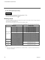
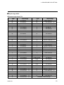
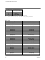
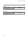
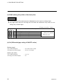
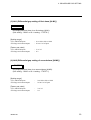
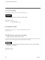
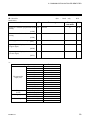
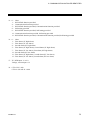
Digital Controller CB100/CB400 CB500/CB700 CB900 Initial Setting Manual ® RKC INSTRUMENT INC. IMCB04-E2 CAUTIONS l This manual is subject to change without prior notice. l Examples of figures, diagrams and numeric values used in this manual are for a better understanding of the text, but not for assuring the resultant operation. l This manual is may not be reproduced or copied in whole or in part without RKC's prior consent. l This instrument and manual are manufactured, prepared, then shipped under strict quality control. However, if any defect is found, please contact your nearest RKC sales office or agent from which you bought the system. l RKC assumes no responsibility for any of the following damage which the user or third party may suffer. (1) Damage incurred as a result of using this product. (2) Damage caused by product failure which cannot be predicted by RKC. (3) Other indirect damage. All Rights Reserved, Copyright 1998, RKC INSTRUMENT INC. INTRODUCTION Before using this instrument, please carefully read this manual for its correct use. In addition, after reading the manual keep it available easily anytime. USERS OF THIS MANUAL This manual is written mainly for personnel who have a fundamental knowledge of electricity as well as control. This manual is also written for RKC service engineers or qualified technicians. ! WARNING WIRING PRECAUTIONS • If failure or error of this instrument could result in a critical accident of the system, install an external protection circuit to prevent such an accident. • In order to prevent instrument damage or failure, protect the power line and the input/output lines from high currents by using fuses with appropriate ratings. POWER SUPPLY • In order to prevent instrument damage or failure, supply power of the specified rating. • In order to prevent electric shock or instrument failure, do not turn on the power supply until all of the wiring is completed. NEVER USE THE INSTRUMENT NEAR FLAMMABLE GASES. In order to prevent fire, explosion or instrument damage, never use this instrument at a location where flammable or explosive gases or vapor exist. NEVER TOUCH THE INSIDE OF THE INSTRUMENT. In order to prevent electric shock or burns, never touch the inside of the instrument. Only RKC service engineers can touch the inside of the instrument to check the circuit or to replace parts. High voltage and high temperature sections inside the instrument are extremely dangerous. NEVER MODIFY THE INSTRUMENT. In order to prevent accident or instrument failure, never modify the instrument. MAINTENANCE • In order to prevent electric shock, burns or instrument failure, only RKC service engineers may replace parts. • In order to use this instrument continuously and safely, conduct periodic maintenance. Some parts used in this instrument have a limited service life and may deteriorate over time. IMCB04-E2 i-1 INSTRUMENT SAFETY CAUTIONS l This instrument is designed to be mounted on instrumentation panels. It is therefore manufactured as part of the final product to facilitate wiring. This means that unauthorized personnel can easily access the high-voltage sections in this instrument such as power terminals, etc. Therefore, when this instrument is installed on the final product, the user should take the necessary measures for the final product to ensure that unauthorized personnel cannot access the high-voltage sections, etc. l In order to use this instrument correctly and safely, always observe the cautions described in this manual when performing operations and maintenance. RKC assumes no responsibility for any injury or accident resulting from not following these cautions. NOTES ON INDICATIONS The following indications are used in this manual to ensure the safe, correct use of the CB100/CB400/CB500/CB700/CB900. SIGNAL WORDS WARNING : Where there are possible dangers such as electric shock, fire (burns), etc. Which could cause loss of life or injury, precautions to avoid such dangers are CAUTION : These describe precautions to be taken in case unit damage may result if operating procedures are not strictly followed. NOTE : Extra noted or precautions are added to operating procedures and explanations. SYMBOL MARKS ! ∗ : This mark is used when great care is needed especially for safety. : This mark is used to add extra notes, precautions or supplementary explanations to table and figures. CAUTIONS PRIOR TO USE l This instrument is intended to be used under the following environmental conditions. (IEC1010) [OVERVOLTAGE CATEGORY II, POLLUTION DEGREE 2] l To the instrument with power supply of 24V, please be sure to supply the power from SELV circuit. l Before cleaning the instrument, check that the power is turned off. l Remove stains on the display unit using a soft cloth or tissue paper. l As the display unit is easily scratched, do not scrub or touch it with a hard object. l The stains on the housing shall be wiped off by the cloth which is dipped into the neutral cleanser diluted by water and wrung tightly, and finish it by a dried cloth. CE CONFORMED INSTRUMENT CAUTIONS l This instrument is protected from electric shock by reinforced insulation. So please arrange reinforced insulation to the wire for input signal against the wires for instrument power supply, source of power and loads as far as possible. l EN55022, EN50082-2 and EN61010-1 are applicable to this instrument. ! WARNING This is a Class A (EN55022) instrument. In a domestic environment this instrument may cause radio interference, in which case the user is required to take adequate measures. i-2 IMCB04-E2 Name and number of this instruction manual : Name : Digital Controllers CB100/CB400/CB500/CB700/CB900 Initial Setting Manual Manual number : IMCB04-E2 n Revisions Date of revision Manual number May 29, 1998 IMCB04-E1 The first edition issue October 9, 1998 IMCB04-E2 Changed items : Key operation time, page format IMCB04-E2 Reason for revision i-3 CONTENTS 1. TRANSFER TO MODE ...................................................................... 1 1.1 Transfer to initialization mode..........................................................................1 1.2 End of initialization mode.................................................................................3 2. PROCEDURE FOR SETTING............................................................ 4 2.1 Display flowcharts in initialization mode...........................................................4 2.2 Procedure for setting each parameter .............................................................5 2.3 Details of parameters in initialize code 0 (Cod=0) ...........................................8 2.4 Details of parameters in initialize code 1 (Cod=1) .........................................17 2.5 Details of parameters in initialize code 2 (Cod=2) .........................................26 3. COMMUNICATION INITIALIZE IDENTIFIER................................... 27 nList of communication initialize identifiers .........................................................27 i-4 IMCB04-E2 1. TRANSFER TO MODE Initialization is to set parameters relating to instrument specifications (input type, input range, alarm type, etc.) and those relating to instrument characteristics (setting limiter, alarm differential gap, etc.). 1.1 Transfer to initialization mode • Turn on the power to this instrument. Thus, the input type, input range and PV/SV display mode change in this order. ‚ Press the SET key for 2 sec with the instrument set to PV/SV display mode to change the instrument to parameter setting mode. *For details on parameter setting mode, see the instruction manual for CB100 [IMCB01-E¨] or CB400/CB500/CB700/CB900 [IMCB02-E¨]. ƒ Press the SET key to change to the set data lock function display screen. „ Press the <R/S key to light brightly the thousands digit on the set value (SV) display unit. S e t d at a l o c k f u n ctio n dis pl a y As the units digit light brightly first, press the <R/S key to light brightly the thousands digit. PV SV AT S ET O UT1 O U T2 AL M 1 AL M 2 Bright lighting : R/S Dim lighting : … Press the UP key to change "0" to "1" in the thousands digit. S et d a ta l o c k f u n cti o n dis pla y Set value 0 : Initialization mode locked 1 : Initialization mode unlocked PV SV AT SET O UT1 O U T2 AL M 1 AL M 2 Bright lighting : R/S Dim lighting IMCB04-E2 : 1 1. TRANSFER TO MODE † Press the SET key to change to the next parameter. Thus, the data in initialization mode is unlocked. C T 1 i n p u t dis pl a y PV SV O UT1 AT SET O UT2 ALM1 ALM2 R/S *In the above figure, the CT1 input is displayed. However, the parameter to be displayed varies depending on the specification. ‡ Keep pressing both the SET and <R/S keys for 2 sec to change the instrument to initialization mode. Thus, the symbol (Cod) for selecting the initialize code is displayed first. Selecting and displaying initialize C T 1 i n p ut dis p la y code in initialization mode PV PV SV SV Bright lighting : AT SET 2 R/S OUT1 OUT2 ALM1 AT ALM2 SET R/S O UT1 O UT2 ALM1 ALM2 Dim lighting : IMCB04-E2 1. TRANSFER TO MODE 1.2 End of initialization mode • Transfer to "Initialize code selection" after each parameter is set. ‚ Simultaneously keep pressing both the SET and <R/S keys for 2 sec in the "Initialize code selection" state to transfer to "PV/SV display mode." ƒ Press the SET key for 2 sec in the "PV/SV display mode" state to transfer to parameter setting mode. „ Press the SET key to transfer to the set data lock function display. … Press the <R/S key to brightly light the thousands digit on the set value (SV) display unit. (See „ on P.1.) † Press the DOWN key to set the numeric value corresponding to the thousands digit to "0" from "1." S e t d a t a l o c k f u n c ti o n d i s p l a y PV Set value 0 : Initialization mode locked 1 : Initialization mode unlocked SV AT SET O UT1 O UT2 AL M 1 AL M 2 Bright lighting : R/S Dim lighting : ‡ Press the SET key to transfer to the next parameter. As a result, the "Initialization mode lock state" setting becomes effective. C T1 input display PV SV AT S ET O UT1 O UT2 AL M 1 AL M 2 R/S *In the above figure, the CT1 input is displayed. However, the parameter to be displayed varies depending on the specification. IMCB04-E2 3 2. PROCEDURE FOR SETTING If the instrument is changed to initialization mode, the symbol (Cod) for selecting the initialize code is displayed first. (Initializing items are classified into 3 initialize code groups in initialization mode.) Enter the initialize code corresponding to the parameter to be changed, and then select the parameter to be changed by pressing the SET key. The measured value (PV) display unit shows the characters corresponding to the parameter, and the set value (SV) display unit shows the value corresponding to that parameter. Display flowcharts in initialization mode are shown in the following. 2.1 Display flowcharts in initialization mode CAUTION There are parameters which are not displayed depending on the specification. Press the SET and <R/S keys simultaneously PV/SV display mode Press the SET key for 2 sec. Parameter setting mode Press the SET and <R/S keys simultaneously for 2 sec. Keep pressing the SET and <R/S keys simultaneously for 2 sec with the set data unlocked. Explaining the arrow mark : Press the SET key. Set " Initialize code selection " to 0. Set " " to 1. Set " (TC J) (SLH ) Engineering unit and cooling type selection (SL2) Heater break alarm , control loop break alarm, (SL3) special specification, or control loop break alarm output selection (SLL) S etting lim iter [low lim it] Operating time display unit (Upper digits) (W TH ) Operating time display unit (Lower digits) Se tting the position of decim a l po in t (W TL) (PG dP) D iffe rentia l gap se tting of (oH ) ON /O FF action F irst alarm (ALM 1) type o r first a larm (ALM 1) " to 2. Holding peak ambient temperature S etting lim iter [h igh lim it] Inpu t type se lection (SL1) *Parameters in this initialize code are only displayed. D iffe rentia l gap se tting of first a la rm (SL4) w ith ho ld action (AH1 ) (ALM 1) Second a la rm (ALM 2) type or second a la rm (SL5) (ALM 2) w ith ho ld action (AH2 ) a larm (ALM 2 ) (SL6) Communication setting mode D iffe rentia l gap se tting of second Con tro l action type se lection C T ra tio setting (C Tr) Energ ized /de -energized a la rm se lection , (SL7) specia l specifica tion se lection 1 D igita l filte r setting (dF) Time factor assumed to be safe setting Specia l specifica tion 2 (SL8) (STTM) Factor to calculate proportional band Specia l specifica tion 3 (SL9) (STPK) setting Factor to calculate derivative time setting O ption se lection (SL10) (STIK) SV alarm type selection (SL11) Initialize code selection 4 IMCB04-E2 2. PROCEDURE FOR SETTING 2.2 Procedure for setting each parameter [Example of changing the setting] When the display unit shows "Engineering unit and cooling type selection (SL2)" in initialize code "0," the following procedure is for changing the temperature unit from "°F" to "°C" or the cooling method from "Water cooling" to "Air cooling." • Change the instrument to the initialize code selection display. (See "1.1 Transfer to initialization mode" on page 1.) Selecting and displaying initialize code PV SV AT SET O U T1 O U T2 ALM 1 ALM 2 R/S ‚ As "Engineering unit and cooling type selection (SL2)" belongs to the group of initialize code "0," do not change the initialize code (the units digit) but press the SET key to change to "Engineering unit and cooling type selection (SL2)." Selecting and displaying initialize code PV PV SV SV AT SET NOTE Engineering unit (°C,°F) and cooling type selection O U T1 O U T2 AL M 1 AL M 2 R/S AT SET O U T1 O U T2 AL M 1 AL M 2 R/S Please read this NOTE without fail. When the initialize code is set to "1" or "2," enter "1" or "2" in the units digit of the set value (SV) display unit by pressing the UP or DOWN key. IMCB04-E2 5 2. PROCEDURE FOR SETTING ƒ Press the DOWN key to enter "0" in the units digit of the set value (SV) display unit. Engineering unit (°C,°F) and cooling type selection Set value : 0 : °C 1 : °F PV SV AT SET O U T1 O U T2 A LM 1 AL M 2 R/S „ Press the <R/S key to move the brightly lit digit of the set value (SV) display unit to the tens digit. The brightly lit digit moves as follows every time the <R/S key is pressed. … Press the UP key to enter "1" in the tens digit of the set value (SV) display unit. Engineering unit (°C,°F) and cooling type selection Set value : 0 : Air cooling 1 : Water cooling PV SV AT SET 6 O U T1 O U T2 A LM 1 ALM 2 R/S IMCB04-E2 2. PROCEDURE FOR SETTING † Press the SET key to change to the next parameter. Thus, the set value is registered. Heater break alarm(HBA), control loop break alarm(LBA), special specification, or control loop break alarm (LBA) output selection PV SV AT SET IMCB04-E2 O U T1 O U T2 ALM 1 AL M 2 R/S 7 2. PROCEDURE FOR SETTING Parameter display position PV Measured value (PV) display unit shows parameter No. SV Input the numerical value in the set value (SV) *Note that the relevant digit used differs depending on the Set value 0 1 The figure at the above is for selects the "Water cooling" in "SL2 (Engineering unit and cooling type selection)". The details of parameters in each initialize code group are described in the following. 2.3 Details of parameters in initialize code 0 (Cod = 0) (1) SL1 (Input type selection) CAUTION Conduct the setting so that it matches the instrument specification (input type). If the setting is changed, always re-set the setting limits (SLH and SLL). (See P.17, 18) Factory set value varies depending on the input type. Set value Input type 0 0 0 0 K 0 0 0 1 J 0 0 1 0 L 0 0 1 1 E 0 1 0 0 N Thermocouple input 0 1 1 1 R (TC) 1 0 0 0 S *2 1 0 0 1 B 1 0 1 0 W5Re/W26Re 1 0 1 1 PL II 0 1 0 1 T 0 1 1 0 U 1 1 0 0 RTD input Pt100 Ω (JIS/IEC) *2 1 1 0 1 JPt100 Ω (JIS) 1 1 1 0 0 to 5 V DC Voltage input *2 1 1 1 1 1 to 5 V DC 1 1 1 0 0 to 20 mA DC Current input *1, *2 1 1 1 1 4 to 20 mA DC *1 : For the current input specification, a resistor of 250 Ω must be connected between the input terminals. *2 : No input type (TC/RTD input to voltage/current input or voltage/current input to TC/RTD input) cannot be changed. 8 IMCB04-E2 2. PROCEDURE FOR SETTING (2) SL2 (Engineering unit and cooling type selection) CAUTIONS l For the voltage and current input types, the engineering unit setting of °C or °F is ignored. l When control action is of the type D (PID action with autotuning [direct action]) or type F (PID action with autotuning [reverse action]), "Cooling type selection" setting is ignored. l Any digits other than the tens digit are not used. As malfunction may result, do not change any of these digits. Factory set value varies depending on the instrument specification. Set value Description Engineering unit selection 0 °C 1 °F 0 Air cooling (A type) *1 Cooling type selection 1 Water cooling (W type) *2 0 0 Fixed *1 : A type : Heat/cool PID action with autotuning (Air cooling) *2 : W type : Heat/cool PID action with autotuning (Water cooling) IMCB04-E2 9 2. PROCEDURE FOR SETTING (3) SL3 (Heater break alarm [HBA], control loop break alarm [LBA], special specification, or control loop break alarm [LBA] output selection ) CAUTIONS l "With heater break alarm (HBA) function" setting is ignored for the following instruments. Ÿ Instrument with deviation or process alarm as the second alarm (ALM2). Ÿ Instrument whose control output is the current output type. l "With control loop break alarm (LBA) function" setting is ignored for the following instruments. Ÿ When "Control loop break alarm (LBA)," and "Input alarm" or "Deviation alarm" are simultaneously selected as "First alarm (ALM1)" or "Second alarm (ALM2)." Ÿ When "Control loop break alarm (LBA)" is selected as "2nd alarm" with "Heater break alarm (HBA)" provided. Ÿ Instrument whose control action is the W type (Heat/Cool PID action with autotuning [Water cooling]) or A type (Heat/cool PID action with autotuning [Air cooling]). Ÿ "SL3" setting displays are only "0" and "1." Factory set value varies depending on the instrument specification. Set value Description 0 Heater break alarm (HBA) not provided Heater break alarm (HBA) selection 1 Heater break alarm (HBA) provided 0 Control loop break alarm (LBA) not provided Control loop break alarm (LBA) selection 1 Control loop break alarm (LBA) provided 0 Z-132 specification not provided *1 Special specification selection 1 Z-132 specification provided *2 0 LBA is output from "First alarm" Selection of control loop break 1 LBA is output from "Second alarm" alarm (LBA) output terminals *1 : Normal HBA action. *2 : HBA occurs 3 sec after the burnout function is activated. 10 IMCB04-E2 2. PROCEDURE FOR SETTING (4) SL4 (First alarm [ALM1] type or first alarm [ALM1] with hold action selection) CAUTION The following instrument is set to "0000." Ÿ Instrument without the first alarm (ALM1). Ÿ Instrument which outputs control loop break alarm (LBA) from the first alarm side. (SL3 setting details : For "0010") Set value 0 0 0 0 0 1 0 1 0 0 1 1 1 0 1 1 1 0 1 1 1 0 1 IMCB04-E2 Factory set value varies depending on the instrument specification. Description First alarm (ALM1) not provided Deviation high alarm Deviation high/low alarm First alarm (ALM1) type selection Process high alarm Deviation low alarm Band alarm Process low alarm Without alarm hold action First alarm (ALM1) with hold action selection With alarm hold action 11 2. PROCEDURE FOR SETTING (5) SL5 (Second alarm [ALM2] type or second alarm [ALM2] with hold action selection) CAUTION The following instrument is set to "0000." Ÿ Instrument without the second alarm (ALM2). Ÿ Instrument with the heater break alarm (HBA). Ÿ Instrument which outputs control loop break alarm (LBA) from the second alarm side. (SL3 setting details : For "1010") Set value 0 0 0 0 0 1 0 1 0 0 1 1 1 0 1 1 1 0 1 1 1 0 1 12 Factory set value varies depending on the instrument specification. Description Second alarm (ALM2) not provided Deviation high alarm Deviation high/low alarm Second alarm (ALM2) type Process high alarm selection Deviation low alarm Band alarm Process low alarm Without alarm hold action Second alarm (ALM2) with hold action selection With alarm hold action IMCB04-E2 2. PROCEDURE FOR SETTING (6) SL6 (Control action type selection) CAUTIONS l Conduct setting so as to meet the instrument specification. An incorrect setting may cause a malfunction. l When control action is of the type D or F, "Control action type selection (Cool-side)" setting is ignored. Factory set value varies depending on the instrument specification. Set value Description 0 Direct action (D type) Direct/reverse action selection 1 Reverse action (F, A and W type) 0 PID action with autotuning *1 Control action type selection 1 Heat/Cool PID action with autotuning *2 0 Heat-side time proportioning output (M, V, G and T output) *3 Control output type selection (Heat-side) 1 Heat-side continuous output (Current 4 to 20 mA DC) 0 Cool-side PID action with autotuning (M, V and T output) *3 Control output type selection (Cool-side) 1 Cool-side continuous output (Current output 4 to 20 mA DC) *1 žžž D type : PID action with autotuning (Direct action) F type : PID action with autotuning (Reverse action) *2 žžž A type : Heat/cool PID action with autotuning (Air cooling) W type : Heat/cool PID action with autotuning (Water cooling) *3 žžž M output : Relay contact output G output : Trigger (for triac driving) output V output : Voltage pulse output T output : Triac output IMCB04-E2 13 2. PROCEDURE FOR SETTING (7) SL7 (Energized/de-energized alarm selection, special specification selection 1) CAUTION Instrument without the first alarm (ALM1) and second alarm (ALM2) is set to "0000." Ÿ Instrument without the second alarm (ALM1). [SL4 setting details : For "0000"] Ÿ Instrument without the second alarm (ALM2). [SL5 setting details : For "0000"] Factory set value : "0000" Set value Description 0 1 Energized alarm De-energized alarm Energized alarm/De-energized alarm selection (First alarm side) 0 Energized alarm Energized alarm/De-energized alarm selection 1 De-energized alarm (Second alarm side) 0 Z-124 specification not provided *1 Special specification selection (First alarm side) 1 Z-124 specification provided *2 0 Z-124 specification not provided *1 Special specification selection (Second alarm side) 1 Z-124 specification provided *2 *1 : The alarm output is forcibly turned ON when the burnout function is activated. *2 : No alarm action is taken by the burnout function. (Same as the normal alarm action.) (8) SL8 (Special specification selection 2) CAUTION Any digits other than the tens digit are not used. As malfunction may result, do not change any of other digits. Factory set value : "0000" Set value Description 0 Z-185 specification not provided *1 Special specification selection 1 Z-185 specification provided *2 0 0 0 Fixed *1 : Normal control in the direct or reverse action is performed even if the burnout function is activated or not. *2 : The control output is forcibly turned ON when the burnout function is activated. 14 IMCB04-E2 2. PROCEDURE FOR SETTING (9) SL9 (Special specification selection 3) CAUTIONS l Any item set in the "Z-168" specification has priority over that set in SL3 (heater break alarm selection). l Any digits other than the units digit are not used. As malfunction may result, do not change any of other digits. Factory set value : "0000" Set value Description Z-168 specification not provided *1 Special specification selection Z-168 specification provided *2 0 0 0 Fixed *1 : It becomes the item set in SL3 (heater break alarm selection). *2 : Heater break alarm for three-phase heater. 0 1 (10) SL10 (Option selection) CAUTIONS l For the A or W control action type, there is no self-tuning function (0 : self-tuning not provided). l The tens digits is not used. As malfunction may result, do not change this digit. Factory set value : "1001" Set value Description 0 1 0 0 1 0 1 IMCB04-E2 RUN/STOP not provided RUN/STOP provided Fixed Communication function not provided Communication function provided Self-tuning not provided Self-tuning provided Selection of RUN/STOP function Selection of communication function Selection of self-tuning function 15 2. PROCEDURE FOR SETTING (11) SL11 (SV alarm type selection) CAUTIONS l For the instrument without "First alarm (ALM1)" or "Second alarm (ALM2)," always set it to "0 : first alarm, SV alarm not provided," or "0 : second alarm, SV alarm not provided." l The following conditions must be satisfied in order to effectuate "SV alarm." Ÿ When setting the instrument to "First alarm, SV alarm provided" "First alarm (ALM1) type or first alarm (ALM1) with hold action selection (SL4)" should be set to "0000." The content of the "SL4" setting has priority over that of the "SL11" setting. Ÿ When setting the instrument to "Second alarm, SV alarm provided" "Second alarm (ALM2) type or second alarm (ALM2) with hold action selection (SL5)" should be set to "0000." The content of the "SL5" setting has priority over that of the "SL11" setting. Factory set value : "0000" Set value 0 1 0 1 0 1 0 1 16 Description First alarm, SV alarm not provided First alarm, SV alarm provided First alarm, SV high alarm First alarm, SV low alarm Second alarm, SV alarm not provided Second alarm, SV alarm provided Second alarm, SV high alarm Second alarm, SV low alarm Selection of first alarm, SV alarm Selection of first alarm, SV alarm type Selection of second alarm, SV alarm Selection of second alarm, SV alarm type IMCB04-E2 2. PROCEDURE FOR SETTING 2.4 Details of parameters in initialize code 1 (Cod = 1) (1) SLH (Setting limiter [high limit]) CAUTIONS l Set the limiter by referring to "Input range table" (P.19) l Limiter setting becomes SLH SLL. n Setting method Press the <R/S key to move the digit, then enter the high limit of the set value (SV) by pressing the UP or DOWN key. The set value (SV) display unit shows the numeric value. Factory set value varies depending on the instrument specification. Input type Setting range K 0 to 1372 °C (0 to 2502 °F) J 0 to 1200 °C (0 to 2192 °F) R 0 to 1769 °C (0 to 3216 °F) S 0 to 1769 °C (0 to 3216 °F) B 0 to 1820 °C (0 to 3308 °F) Thermocoupl E 0 to 1000 °C (0 to 1832 °F) e N 0 to 1300 °C (0 to 2372 °F) input (TC) T -199.9 to +400.0 °C (-199.9 to +752.0 °F) W5Re/W26Re 0 to 2320 °C (0 to 4208 °F) PL II 0 to 1390 °C (0 to 2534 °F) U -199.9 to +600.0 °C (-199.9 to +999.9 °F) L 0 to 900 °C (0 to 1652 °F) RTD input Pt100 Ω (JIS/IEC)*1 -199.9 to +649.0 °C (-199.9 to +999.9 °F) JPt100 Ω (JIS) -199.9 to +649.0 °C (-199.9 to +999.9 °F) Voltage 0 to 5V DC -1999 to +9999 input (programmable scale) 1 to 5V DC Current 0 to 20 mA DC*2 -1999 to +9999 input (programmable scale) 4 to 20 mA DC*2 *1 : IEC (International Electrotechnical Commission) is equivalent to JIS, DIN and ANSI. *2 : For the current input specification, a resistor of 250 Ω must be connected between the input terminals. IMCB04-E2 17 2. PROCEDURE FOR SETTING (2) SLL (Setting limiter [low limit] ) CAUTIONS l Set the limiter by referring to "Input range table." (P.19) l Limiter setting becomes SLH SLL. n Setting method Press the <R/S key to move the digit, then enter the low limit value of input range by pressing the UP or DOWN key. The set value (SV) display unit shows the numeric value. Factory set value varies depending on the instrument specification. Input type Setting range K 0 to 1372 °C (0 to 2502 °F) J 0 to 1200 °C (0 to 2192 °F) R 0 to 1769 °C (0 to 3216 °F) S 0 to 1769 °C (0 to 3216 °F) B 0 to 1820 °C (0 to 3308 °F) Thermocoupl E 0 to 1000 °C (0 to 1832 °F) e N 0 to 1300 °C (0 to 2372 °F) input (TC) T -199.9 to +400.0 °C (-199.9 to +752.0 °F) W5Re/W26Re 0 to 2320 °C (0 to 4208 °F) PL II 0 to 1390 °C (0 to 2534 °F) U -199.9 to +600.0 °C (-199.9 to +999.9 °F) L 0 to 900 °C (0 to 1652 °F) RTD input Pt100 Ω (JIS/IEC)*1 -199.9 to +649.0 °C (-199.9 to +999.9 °F) JPt100 Ω (JIS) -199.9 to +649.0 °C (-199.9 to +999.9 °F) Voltage 0 to 5 V DC -1999 to +9999 input (programmable scale) 1 to 5 V DC Current 0 to 20 mA DC*2 -1999 to +9999 input (programmable scale) 4 to 20 mA DC*2 *1 : IEC (International Electrotechnical Commission) is equivalent to JIS, DIN and ANSI. *2 : For the current input specification, a resistor of 250 Ω must be connected between the input terminals. 18 IMCB04-E2 2. PROCEDURE FOR SETTING n Input range table •Thermocouple input (TC) Type K K K K K K K K K K K K K K K J J J J J J J J J J J J R R R R R S S S S IMCB04-E2 Input range 0 to 200 °C 0 to 400 °C 0 to 600 °C 0 to 800 °C 0 to 1000 °C 0 to 1200 °C 0 to 1372 °C 0 to 100 °C 0 to 300 °C 0 to 450 °C 0 to 500 °C 0 to 800 °F 0 to 1600 °F 0 to 2502 °F 20 to 70 °F 0 to 200 °C 0 to 400 °C 0 to 600 °C 0 to 800 °C 0 to 1000 °C 0 to 1200 °C 0 to 450 °C 0 to 800 °F 0 to 1600 °F 0 to 2192 °F 0 to 400 °F 0 to 300 °F 0 to 1600 °C 0 to 1769 °C 0 to 1350 °C 0 to 3200 °F 0 to 3216 °F 0 to 1600 °C 0 to 1769 °C 0 to 3200 °F 0 to 3216 °F *1 *1 *1 *1 *1 *1 *1 *1 *1 Type Input range B 400 to 1800 °C B 0 to 1820 °C B 800 to 3200 °F B 0 to 3308 °F E 0 to 800 °C E 0 to 1000 °C E 0 to 1600 °F E 0 to 1832 °F N 0 to 1200 °C N 0 to 1300 °C N 0 to 2300 °F N 0 to 2372 °F T -199.9 to +400.0 °C T -199.9 to +100.0 °C T -100.0 to +200.0 °C T 0.0 to 350.0 °C T -199.9 to +752.0 °F T -100.0 to +200.0 °F T -100.0 to +400.0 °F T 0.0 to 450.0 °F T 0.0 to 752.0 °F W5Re/W26Re 0 to 2000 °C W5Re/W26Re 0 to 2320 °C W5Re/W26Re 0 to 4000 °F PL II 0 to 1300 °C PL II 0 to 1390 °C PL II 0 to 1200 °C PL II 0 to 2400 °F PL II 0 to 2534 °F U -199.9 to +600.0 °C U -199.9 to +100.0 °C U 0.0 to 400.0 °C U -199.9 to +999.9 °F U -100.0 to +200.0°F U 0.0 to 999.9 °F Continued on the next page. *1 *1 *2 *2 *2 *2 *2 *2 *2 *2 19 2. PROCEDURE FOR SETTING Type Input range L 0 to 400 °C L 0 to 800 °C L 0 to 800 °F L 0 to 1600 °F *1 ⋅⋅⋅⋅ 0 to 399 °C/0 to 799 °F : Accuracy is not guaranteed. *2 ⋅⋅⋅⋅ -199.9 to -100.0 °C/-199.9 to -158.0 °F : Accuracy is not guaranteed. ‚RTD input Type Pt100 (JIS/IEC) Pt100 (JIS/IEC) Pt100 (JIS/IEC) Pt100 (JIS/IEC) Pt100 (JIS/IEC) Pt100 (JIS/IEC) Pt100 (JIS/IEC) Pt100 (JIS/IEC) Pt100 (JIS/IEC) Pt100 (JIS/IEC) Pt100 (JIS/IEC) Pt100 (JIS/IEC) Pt100 (JIS/IEC) Pt100 (JIS/IEC) Pt100 (JIS/IEC) Pt100 (JIS/IEC) Pt100 (JIS/IEC) Pt100 (JIS/IEC) Pt100 (JIS/IEC) JPt100 (JIS) JPt100 (JIS) JPt100 (JIS) JPt100 (JIS) JPt100 (JIS) JPt100 (JIS) JPt100 (JIS) JPt100 (JIS) JPt100 (JIS) JPt100 (JIS) 20 Input range -199.9 to +649.0 °C -199.9 to +200.0 °C -100.0 to +50.0 °C -100.0 to +100.0 °C -100.0 to +200.0 °C 0.0 to 50.0 °C 0.0 to 100.0 °C 0.0 to 200.0 °C 0.0 to 300.0 °C 0.0 to 500.0 °C -199.9 to +999.9 °F -199.9 to +400.0 °F -199.9 to +200.0 °F -100.0 to +100.0 °F -100.0 to +300.0 °F 0.0 to 100.0 °F 0.0 to 200.0 °F 0.0 to 400.0 °F 0.0 to 500.0 °F -199.9 to +649.0 °C -199.9 to +200.0 °C -100.0 to +50.0 °C -100.0 to +100.0 °C -100.0 to +200.0 °C 0.0 to 50.0 °C 0.0 to 100.0 °C 0.0 to 200.0 °C 0.0 to 300.0 °C 0.0 to 500.0 °C IMCB04-E2 2. PROCEDURE FOR SETTING ƒVoltage input Type 0 to 5 V DC 1 to 5 V DC Input range 0.0 to 100.0 % „Current input Type Input range 0 to 20 mA DC 0.0 to 100.0 % 4 to 20 mA DC *For the current input specification, a resistor of 250 Ω must be connected between the input terminals. IMCB04-E2 21 2. PROCEDURE FOR SETTING (3) PGdP (Setting the position of decimal point) CAUTION l The set position of the decimal point is displayed only for current or voltage input. l Any digits other than the units digit are not used. As malfunction may result, do not change any of these digits. Factory set value : "0001" Set value Description 0 2 3 0 No digit below decimal point 1 digit below decimal point 2 digits below decimal point 3 digits below decimal point Fixed Setting the position of decimal point (4) Oh (Differential gap setting of ON/OFF action) [Setting range] •TC and RTD inputs ‚Voltage and current inputs : 0 to 100 or 0.0 to 100.0 : 0.0 to 10.0 of span [Factory set value] •TC and RTD inputs ‚Voltage and current inputs : : 22 2 or 2.0 0.2 IMCB04-E2 2. PROCEDURE FOR SETTING (5) AH1 (Differential gap setting of first alarm [ALM1] ) CAUTION Not displayed when there is no first alarm (ALM1). (SL4 setting : "0000" or SL11 setting : "¨¨¨0.") [Setting range] •TC and RTD inputs ‚Voltage and current inputs : 0 to 100 or 0.0 to 100.0 : 0.0 to 10.0 of span [Factory set value] •TC and RTD inputs ‚Voltage and current inputs : : 2 or 2.0 0.2 (6) AH2 (Differential gap setting of second alarm [ALM2] ) CAUTION Not displayed when there is no second alarm (ALM2). (SL5 setting : "0000" or SL11 setting : "¨0¨¨.") [Setting range] •TC and RTD inputs ‚Voltage and current inputs : : 0 to 100 or 0.0 to 100.0 0.0 to 10.0 of span [Factory set value] •TC and RTD inputs ‚Voltage and current inputs : : 2 or 2.0 0.2 IMCB04-E2 23 2. PROCEDURE FOR SETTING (7) CTr (CT ratio setting) Set the number of times that a wire is wound on to the hole of a CT. CAUTION Not displayed when there is no heater break alarm (HBA). Setting range : 0 to 9999 Factory set value : CTL-6-P-N : 800 CTL-12-S56-10L-N : 1000 (8) dF (Digital filter setting) Setting range : 0 to 100 sec (If "0" is set, the PV digital filter is turned off.) Factory set value : 1 (9) STTM (Time factor assumed to be safe setting) *Displayed when the self-tuning is provided. This is the factor to adjust the reference time of establishing the stabilized state of a measured value. The larger the set value, the longer the time until the measured value is stabilized. CAUTION As this factor is so adjusted that the self-tuning result optimum to most controlled-objects is obtained, do not change it. Setting range : 0 to 200 Factory set value : 100 24 IMCB04-E2 2. PROCEDURE FOR SETTING (10) STPK (Factor to calculate proportional band setting) *Displayed when the self-tuning is provided. This is the factor to adjust the proportional band to be calculated by the self-tuning function. The larger the set value, the larger the proportional band thus calculated. CAUTION As this factor is so adjusted that the self-tuning result optimum to most controlled-objects is obtained, do not change it. Setting range : 0 to 200 Factory set value : 67 (11) STIK (Factor to calculate derivative time setting) *Displayed when the self-tuning is provided. This is the factor to adjust the integral and derivative times to be calculated by the self-tuning function. The larger the set value, the larger the integral and derivative times thus calculated. CAUTION As this factor is so adjusted that the self-tuning result optimum to most controlled-objects is obtained, do not change it. Setting range : 0 to 200 Factory set value : 16 IMCB04-E2 25 2. PROCEDURE FOR SETTING 2.5 Details of parameters in initialize code 2 (Cod=2) Parameters in initialize code 2 are only displayed. (1) TCJ (Holding peak ambient temperature) The maximum ambient temperature on the rear terminal board of the instrument is stored and displayed on the set value (SV) display unit. Display range Display resolution : -10.0 to +100 °C : 1 °C (2) WTH (Operating time display unit [Upper digits] ) The integrated value (upper 2 digits) of power ON time is shown on the set value (SV) display unit. If the total operating time exceeds 100,000 hours, the integrated operating time is reset. Display range : 0000 to 0010 (Operating time from 0 to 100,000 hours can be displayed for both the upper and lower digits.) Display resolution : 10,000 hours (3) WTL (Operating time display unit [Lower digits] ) The integrated value (lower 4 digits) of power ON time is shown on the set value (SV) display unit. If the total operating time exceeds 9,999 hours, these digits move to the operating time display unit [Upper digits] (WTH). Display range Display resolution : 0000 to 9999 : 1 hours n Example : When the integrated value of operating time equals to 100,000 hours. The upper 2 digits of 100,000 hours are shown on the operating time display unit [upper digits] (WTH) and the lower 4 digits are shown on the operating time display unit [lower digits]. Operating time display unit (Upper digits) 26 Operating time display unit (Lower digits) PV PV SV SV IMCB04-E2 3. COMMUNICATION INITIALIZE IDENTIFIER nList of communication initialize identifiers NOTES l Note that there are identifiers which cannot be communicated depending on the specification. For details on the structure of communication data, see the instruction manual for “CB100/CB400/ CB500/CB700/CB900 communications” [IMCB03-E¨]. l The number of digits is 6 for all data. ID : Identifier Read/write) (RO Name ID Initialization mode selection Setting necessary code : Data range Read only R/W : Factory set value R/W IO 0 : RO 1 : R/W 0 R/W IP 0 to 2 0 R/W XI 0 to 15 XQ 0 : °C (Air cooling) [Cod] Input type selection [SL1] Engineering unit and cooling type selection See *1 To vary R/W depending on the specification R/W To vary depending on the specification 1 : °F (Air cooling) 2 : °C (Water cooling) [SL2] Heater break alarm (HBA), control loop break alarm (LBA), special specification, or control loop break alarm (LBA) output selection 3 : °F (Water cooling) R/W To vary depending on the specification LV 0 : No function provided 1 : HBA provided 2 : LBA provided, LBA is output from “First alarm” 5 : HBA (Z-132 specification) provided 10 : LBA provided, LBA is output from “Second alarm” First alarm (ALM1) type or First alarm (ALM1) with hold action selection [SL4] XA 0 to 15 R/W See *2 To vary depending on the specification Second alarm (ALM2) type or Second alarm (ALM2) with hold action selection [SL5] XB 0 to 15 R/W See *2 To vary depending on the specification [SL3] Continued on the next page. IMCB04-E2 27 3. COMMUNICATION INITIALIZE IDENTIFIER ID : Identifier Read/write) (RO Name ID Control action type selection : Read Data range only Factory set value R/W R/W CA 0 to 15 See *3 To vary R/W depending on the specification Energized/de-energized alarm selection, special specification selection 1 [SL7] Z1 0 to 15 See *4 0 R/W Special specification selection 2 Z2 0 : Z-185 specification not provided 2 : Z-185 specification provided 0 R/W Z3 0 : Z-168 specification provided 1 : Z-168 specification not provided 0 R/W [SL6] [SL8] Special specification selection 3 [SL9] Option selection [SL10] DH 0 to 13 See *5 0 R/W SV alarm type selection [SL11] XC 0 to 15 See *6 0 R/W XV See "Input range table" (P.19, 20, 21) Setting limiter (high limt) To vary R/W depending on the specification [SLH] Setting limiter (low limit) [SLL] XW Setting the position of decimal point XU Differential gap setting of ON/OFF action [oH] 0 : No digit below decimal point 1 : 1 digit below decimal point 2 : 2 digits below decimal point 3 : 3 digits below decimal point 1 R/W MH l For TC/RTD inputs : 0 (0.0) to100 (100.0) °C [°F] l For voltage/current inputs : 0.0 to 10.0% of span See *7 R/W See *7 R/W See *8 R/W 0 R/W 100 R/W [PGdP] Differential gap setting of second alarm (ALM2) [AH2] HB l For TC/RTD inputs : 0 (0.0) to100 (100.0) °C [°F] l For voltage/current inputs : For voltage/current inputs : 0.0 to 10.0% of span CT ratio setting XR 0 to 9999 F1 0 to 100 sec GH 0 to 200 Differential gap setting of first alarm (ALM1) HA [AH1] : [CTr] Digital filter setting [dF] Time factor assumed to be safe setting [STTM] Continued on the next page. 28 IMCB04-E2 3. COMMUNICATION INITIALIZE IDENTIFIER ID : Identifier Read/write) (RO Name ID Factor to calculate proportional band setting [STPK] PU Factor to calculate derivative time setting [STIK] Data range : Read only R/W : Factory set value R/W 0 to 200 67 R/W IU 0 to 200 16 R/W Holding peak ambient temperature [TCJ] HP -10 to +100°C 0 RO Operating time display unit (Upper digits) UT 0 to 10 0 RO UU 0 to 9999 0 RO [WTH] Operating time display unit (Lower digits) [WTL] *1... Input type Thermocouple input (TC) RTD input (RTD) Voltage input Current input IMCB04-E2 K J L E N T U R S B W5Re/W26Re PL II Pt100 Ω (JIS/IEC) JPt100 Ω (JIS) 0 to 5 V DC 1 to 5 V DC 0 to 20 mA DC 4 to 20 mA DC Set value 0 1 2 3 4 5 6 7 8 9 10 11 12 13 14 15 14 15 29 3. COMMUNICATION INITIALIZE IDENTIFIER *2... 0 : No alarm 7 : Process low alarm 1 : Deviation high alarm 9 : Deviation high alarm with hold action 2 : Deviation high/low alarm 10 : Deviation high/low alarm with hold action 3 : Process high alarm 11 : Process high alarm with hold action 5 : Deviation low alarm 13 : Deviation low alarm with hold action 6 : Band alarm 15 : Process low alarm with hold action ŸDo not set 4, 8, 12 or 14. Malfunction may result. *3... 0 : PID action with autotuning (Direct action), time proportioning output (relay contact output, voltage pulse output, trigger (for triac driving) output or triac output. 1 : PID action with autotuning (Reverse action), time proportioning output (relay contact output, voltage pulse output, trigger (for triac driving) output or triac output. 3 : Heat/cool PID action with autotuning, heat-side time proportioning output (relay contact output, voltage pulse output, triac output or trigger [for triac driving]) or cool-side time proportioning output (relay contact output, voltage pulse output, triac output). 4 : PID action with autotuning (Direct action) or current output. 5 : PID action with autotuning (Reverse action) or current output. 7 : Heat/cool PID action with autotuning, heat-side current output or cool-side time proportioning output (relay contact output, voltage pulse output, triac output). 11 : Heat/cool PID action with autotuning, heat-side time proportioning output (relay contact output, voltage pulse output, trigger [for triac driving] output or triac output) or cool-side current output. 15 : Heat/cool PID action with autotuning, heat-side current output or cool-side current output. *4... 0 : 1: 2: 3: 4: 5: 6: 7: 8: 9: 10 : 11 : 12 : First alarm (Energized alarm), second alarm (Energized alarm) First alarm (De-energized alarm), second alarm (Energized alarm) First alarm (Energized alarm), second alarm (De-energized alarm) First alarm (De-energized alarm), second alarm (De-energized alarm) First alarm (Energized alarm, Z-124 specification provided), second alarm (Energized alarm) First alarm (De-energized alarm, Z-124 specification provided), second alarm (Energized alarm) First alarm (Energized alarm, Z-124 specification provided), second alarm (De-energized alarm) First alarm (D e-energized alarm , Z -124 specification provided), second alarm (D e-energized alarm) First alarm (Energized alarm), second alarm (Energized alarm, Z-124 specification provided) First alarm (De-energized alarm), second alarm (Energized alarm, Z-124 specification provided) First alarm (Energized alarm), second alarm (De-energized alarm, Z-124 specification provided) First alarm (D e-energized alarm ), second alarm (D e-energized alarm , Z -124 specification provided) First alarm (Energized alarm, Z-124 specification provided), second alarm (Energized alarm, Z-124 specification provided) 13 : First alarm (De-energized alarm, Z-124 specification provided), second alarm (Energized alarm, Z-124 specification provided) 14 : First alarm (Energized alarm, Z-124 specification provided), second alarm (De-energized alarm, Z-124 specification provided) 15 : First alarm (De-energized alarm, Z-124 specification provided), second alarm (De-energized alarm Z-124 specification provided) 30 IMCB04-E2 3. COMMUNICATION INITIALIZE IDENTIFIER *5... 0 : 1: 4: 5: 8: 9: 12 : 13 : None RUN/STOP function provided Communication function provided RUN/STOP function provided, Communication function provided Self-tuning provided RUN/STOP function provided, Self-tuning provided Communication function provided, Self-tuning provided RUN/STOP function provided, Communication function provided, Self-tuning provided *6... 0 : 1: 3: 4: 5: 7: 12 : 13 : 15 : None First alarm (SV high alarm) First alarm (SV low alarm) Second alarm (SV high alarm) First alarm (SV high alarm), second alarm (SV high alarm) First alarm (SV low alarm), first alarm (SV high alarm) Second alarm (SV low alarm) First alarm (SV high alarm), second alarm (SV low alarm) First alarm (SV low alarm), second alarm (SV low alarm) *7... TC, RTD input : 2 or 2.0 Voltage, current input : 0.2 *8... CTL-6-P-N : 800 CTL-12-S56-10L-N : 1000 IMCB04-E2 31 RKC INSTRUMENT INC. HEAD OFFICE: 16-6, KUGAHARA 5-CHOME, OHTA-KU TOKYO 146-8515 JAPAN PHONE: 03-3751-9799 (+81 3 3751 9799) E-mail: [email protected] FAX: 03-3751-8585 (+81 3 3751 8585) IMCB04-E2 OCT.1998