1
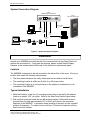
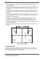
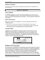
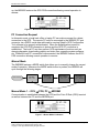
IMS-9000
Intelligent Modem Switch
USER’S MANUAL
Document Part #: RDC-HDWIMS9K100
IMS-9000 User’s Manual
© 2000 Delphi Display Systems, INC. All rights reserved.
Delphi Display Systems, INC. (Delphi) reserves the right to revise or update its products and documents
without notification. Delphi makes no guarantee, implied or expressed regarding the suitability of its
products for any particular purpose, nor does Delphi assume any liability arising out of the application of
use of any of its products or circuits, whether used properly or improperly. No part of this document may
be reproduced, copied or distributed without written permission from Delphi Display Systems, INC.
Delphi Display Systems, INC.
485 E. 17th Street, Suite 400
Costa Mesa, CA 92627
Notice: No part of this document may be reproduced, copied or distributed without
written permission from Delphi Display Systems, INC.
Copyright ©2000. [Unpublished Work]. All rights reserved.
Page 2
IMS-9000 User’s Manual
Contents
IMPORTANT SAFETY INSTRUCTIONS ..............................................................................................................4
INTRODUCTION .......................................................................................................................................................5
PARTS CHECK LIST ....................................................................................................................................................5
FRONT PANEL LAYOUT..............................................................................................................................................5
Front Panel LED Indicators ................................................................................................................................6
Push Buttons ........................................................................................................................................................7
CONNECTOR LAYOUT ................................................................................................................................................7
PC Connector – DB9F .........................................................................................................................................8
Telephone Connectors – RJ11 .............................................................................................................................8
POS Connector ....................................................................................................................................................8
Power Input Connector ........................................................................................................................................8
OCS Connector ....................................................................................................................................................8
SYSTEM CONNECTION DIAGRAM ...............................................................................................................................9
INSTALLATION.........................................................................................................................................................9
LOCATION .................................................................................................................................................................9
TYPICAL INSTALLATION ............................................................................................................................................9
TESTING THE IMS9000............................................................................................................................................10
SOFTWARE INSTALLATION ......................................................................................................................................11
MODES OF OPERATION.......................................................................................................................................11
POWER OFF MODE...................................................................................................................................................11
POWER UP SEQUENCE .............................................................................................................................................11
AUTOMATIC MODE ..................................................................................................................................................11
MODEM Connection Request............................................................................................................................11
PC Connection Request......................................................................................................................................12
MANUAL MODE .......................................................................................................................................................12
Manual Mode 1 – OCS ↔ POS, PC ↔ MODEM .............................................................................................12
Manual Mode 2 – OCS ↔ MODEM, POS ↔ PC .............................................................................................13
Manual Mode 3 – OCS ↔ PC, POS ↔ MODEM .............................................................................................13
MAINTENANCE.......................................................................................................................................................13
IN CASE OF DIFFICULTY.....................................................................................................................................14
STANDARD LIMITED WARRANTY ...................................................................................................................15
IMS9000 TECHNICAL SPECIFICATIONS..........................................................................................................16
AC POWER ADAPTER ..............................................................................................................................................16
IMS9000 UNIT ........................................................................................................................................................16
AGENCY APPROVALS ..............................................................................................................................................16
FCC COMPLIANCE STATEMENT ......................................................................................................................16
TECHNICAL SUPPORT .........................................................................................................................................16
Notice: No part of this document may be reproduced, copied or distributed without
written permission from Delphi Display Systems, INC.
Copyright ©2000. [Unpublished Work]. All rights reserved.
Page 3
IMS-9000 User’s Manual
List of Figures
FIGURE 1 - FRONT PANEL LAYOUT.................................................................................................................................5
FIGURE 2 - CONNECTOR LAYOUT ...................................................................................................................................7
FIGURE 3 - SYSTEM CONNECTION DIAGRAM .................................................................................................................9
FIGURE 4 - REAR PANEL LAYOUT ................................................................................................................................10
FIGURE 5 - DEFAULT CONNECTION INDICATORS (AUTOMATIC MODE)........................................................................11
FIGURE 6 - MODEM/OCS CONNECTION INDICATORS (AUTOMATIC MODE) .................................................................12
FIGURE 7 - MANUAL MODE 1 INDICATORS ..................................................................................................................12
FIGURE 8 - MANUAL MODE 2 INDICATORS ..................................................................................................................13
FIGURE 9 - MANUAL MODE 3 INDICATORS ..................................................................................................................13
Important Safety Instructions
When using your IMS9000 Intelligent Modem Switch product, the following safety
precautions should be followed to reduce the risk of file, electric shock and
personal injury.
•
Read and understand all instructions.
•
Follow all warnings and instructions marked on the product.
•
Do not spill liquid on this product.
•
Unplug the product from the wall outlet before cleaning. Do not use liquid or
aerosol cleaners. Use a damp clean cloth when cleaning.
•
This product should be operated only from the type of power source indicated on
the rear panel label.
•
Do not overload wall outlets and extension cords as this can result in the risk of
fire or electric shock.
•
Refer all servicing of this product to a Delphi authorized service facility.
SAVE THESE INSTRUCTIONS
Notice: No part of this document may be reproduced, copied or distributed without
written permission from Delphi Display Systems, INC.
Copyright ©2000. [Unpublished Work]. All rights reserved.
Page 4
IMS-9000 User’s Manual
Introduction
Congratulations on your purchase of the IMS9000 Intelligent Modem Switch. The
IMS9000 has been designed to work with your Delphi Drive-Thru Order Confirmation
System (OCS) also known as Customer Order Display (COD) and Order Confirmation
Board (OCB). It allows you to remotely update your OCS configuration, daypart, and
graphic files via standard dial up access. In addition, the IMS9000 functions as a
diagnostic tool for quickly troubleshooting Point of Sale, OCS or cabling problems in the
restaurant.
This manual is designed to familiarize you with the IMS9000 features and operation.
We strongly recommend you read the manual before installing or using this product.
Parts Check List
The following parts are included with your IMS9000 product. If anything is missing,
please contact Delphi Display Systems at the number listed in the back of this manual
for replacement parts.
1.
2.
3.
4.
5.
6.
IMS9000 Unit
AC Power Adapter
Telephone Cord
Wall Mounting Hardware (2 ea. #8 screws, 2 ea. wall anchors)
User’s Manual
Configuration Tool Software CD and Documentation
Front Panel Layout
Figure 1 - Front Panel Layout
Notice: No part of this document may be reproduced, copied or distributed without
written permission from Delphi Display Systems, INC.
Copyright ©2000. [Unpublished Work]. All rights reserved.
Page 5
IMS-9000 User’s Manual
Front Panel LED Indicators
The front panel indicators are organized into five groups. The functions of each group
are described in the following sections.
Mode Indicator LEDs
The Mode Indicator LEDs are used to determine the various modes of operation.
LED Indicator
Function
REQ
Flashes when a mode change request is made. A mode change request can
come from the MODEM (call answer or hang up), or from an external PC
connected to the PC port connection.
Flashes in a heart beat pattern during Automatic mode of operation. This is
the default mode of operation after power-up or reset.
When ON, indicates the OCS interface is in RS485 mode. When off, the
OCS interface is in RS232 mode. This mode is set via a jumper on the
IMS9000 circuit board.
Indicates the OCS is connected to the PC port.
Indicates the PC port is connected to the MODEM.
Indicates the OCS is connected to the MODEM.
Indicates the POS is connected to the PC port.
Indicates the OCS is connected to the POS port. This is the default mode of
operation after power-up or reset.
Indicates the POS port is connected to the MODEM.
AUTO
RS485
OCS-PC
PC-MODEM
OCS-MODEM
POS-PC
OCS-POS
POS-MODEM
Table 1 – Mode Indicator LEDs
PC Status LED Indicators
These LED indicators provide information on the activity over the PC RS232
communications port.
LED Indicator
Function
TXD
RXD
RTS
CTS
DTR
DSR
Transmit Data.
Receive Data.
Request to Send.
Clear to Send.
Data Terminal Ready.
Data Set Ready.
Table 2 - PC Status LEDs
Modem Status LED Indicators
LED Indicator
Function
TXD
RXD
DCD
Transmit Data.
Receive Data.
Data Carrier Detect. This LED is illuminated when a telephone connection is
established and remains illuminated until the connection is dropped.
Data Terminal Ready.
DTR
Table 3 - MODEM Status LEDs
Notice: No part of this document may be reproduced, copied or distributed without
written permission from Delphi Display Systems, INC.
Copyright ©2000. [Unpublished Work]. All rights reserved.
Page 6
IMS-9000 User’s Manual
POS Status LED Indicators
LED Indicator
Function
TXD
RXD
RTS
CTS
DTR
DSR
Transmit Data.
Receive Data.
Request to Send.
Clear to Send.
Data Terminal Ready.
Data Set Ready.
Table 4 - POS Status LEDs
OCS Status LED Indicators
LED Indicator
Function
TXD
RXD
PASS
Transmit Data. This LED flashes when data is transmitted to the OCS.
Receive Data. This LED flashes when data is received from the OCS.
OCS Test Status Indicator. GREEN indicates Pass, RED indicates Fail.
Table 5 - OCS Status LEDs
Push Buttons
There are three (3) push buttons on the front panel of the IMS9000.
RESET
The RESET push button resets the IMS9000 and puts it into its power-up condition.
Any telephone connections are immediately dropped and the unit returns to Automatic
mode of operation (POS connected to the OCS).
MODE
The MODE switch manually cycles through each mode of operation. Each time the
button is pressed, the IMS9000 advances to the next mode until it returns to Automatic
mode.
OCS TEST
The OCS TEST button performs a self-test of the OCS when it is connected. The
results of the self-test are displayed on the PASS LED indicator. Green indicates PASS
and Red indicates FAIL.
Connector Layout
PC (optional)
Line Phone
POS
PWR
OCS
Figure 2 - Connector Layout
Notice: No part of this document may be reproduced, copied or distributed without
written permission from Delphi Display Systems, INC.
Copyright ©2000. [Unpublished Work]. All rights reserved.
Page 7
IMS-9000 User’s Manual
PC Connector – DB9F
The PC connector allows a direct connection to a PC serial communication port via a
standard straight-through wired serial extension cable.
Telephone Connectors – RJ11
CAUTION: TO REDUCE THE RISK OF FIRE, USE NO.26AWG OR LARGER
TELECOMMUNICATION LINE CORD.
Line
The Line connector is used to connect the IMS9000 to the telephone line via a standard
telephone cord (supplied).
Phone
This Phone connector allows a telephone, fax, or other telecom device access to the
telephone line when the IMS9000 internal modem is not being used.
Note: The IMS9000 is preset at the factory to answer on the 4th ring.
POS Connector
The POS connector allows a direct connection to the Point Of Sale terminal serial
communication port via a standard straight-through wired serial extension cable.
Power Input Connector
The Power Input connector accepts power from the AC Power Adapter (supplied).
CAUTION: ONLY USE THE AC POWER ADAPTER PROVIDED WITH YOUR
IMS9000.
OCS Connector
The Order Confirmation System is connected to the OCS connector using the serial I/O
cable supplied with the OCS equipment. The I/O cable is terminated with a female DB9
connector. The OCS connector supports both RS232C and RS422 serial
communication standards and is optically isolated to protect all connected equipment.
Notice: No part of this document may be reproduced, copied or distributed without
written permission from Delphi Display Systems, INC.
Copyright ©2000. [Unpublished Work]. All rights reserved.
Page 8
IMS-9000 User’s Manual
System Connection Diagram
Delphi
IMS9000 Intelligent Modem Switch
Delphi
Order Confirmation System
PC (optional)
Line Phone
POS
PWR
RS232 / RS422
I/O Cable
RS232
Serial
Cable
Telephone
Cord
Back Office PC
(Optional)
OCS
RS232
Serial
Cable
Telephone
Cord
Point of Sale Terminal
Modem
Phone
Line
Telephone
Company
Phone
Line
Laptop or Desktop PC
Telephone
Figure 3 - System Connection Diagram
Installation
Unpack your IMS9000 and verify that all of the contents listed in the Parts Check List
section are accounted for. If any parts are missing, please contact Delphi Display
Systems at the number listed in the back of this manual for replacement parts.
Location
The IMS9000 is designed to be wall mounted in the back office of the store. Choose a
location that meets the following requirements:
•
The front panel indicators are easily visible and can be observed at all times.
•
The mounting location is within six (6) feet of an AC power outlet.
•
The mounting location is in close proximity to the telephone (modem) line to be
connected to the IMS9000.
Typical Installation
1. Mark the locations of the two (2) mounting screw holes on the wall in the desired
location at exactly 3.50” on center. Refer to the Rear Panel Layout figure below.
2. Drill two pilot holes and install the two #8 screws provided. Allow each screw to
protrude from the wall approximately 1/8” so that it will lock into the rear panel
keyholes of the IMS9000. In locations where installing to drywall, use the supplied
anchors if necessary. To install anchors, drill two ¼” holes and insert the anchors
flush to the wall surface.
Notice: No part of this document may be reproduced, copied or distributed without
written permission from Delphi Display Systems, INC.
Copyright ©2000. [Unpublished Work]. All rights reserved.
Page 9
IMS-9000 User’s Manual
3. Install the IMS9000 over the two screws and adjust the screws as necessary to
obtain a secure fit.
4. Connect the DB9 Female connector on the end of the OCS Serial I/O Cable to the
OCS connector on the IMS9000. Secure with the screws provided on the cable
connector.
5. Connect the DB9 Male connector of the Point of Sale serial extension cable to the
POS connector on the IMS9000. Secure with the screws provided on the cable
connector.
6. If a connection to the back office PC or laptop computer is desired, connect the
serial extension cable to the PC connector on the IMS9000. Secure with the screws
provided on the cable connector.
7. Connect one end of the Phone Cord (provided) to the LINE connector on the
IMS9000. Connect the other end to the phone jack in the back office. A fax
machine or telephone may be connected to the PHONE connector if desired.
8. Plug the AC Power Supply cord into the Power connector of the IMS9000 and plug
into an AC Power Outlet.
9. Secure all cables with ties and strain reliefs to prevent accidental disconnection or
damage.
3.50"
Figure 4 - Rear Panel Layout
Testing the IMS9000
Upon applying power to the IMS9000, verify that the front panel indicators briefly
illuminate and the AUTO indicator beings to flash in a heart beat mode. Refer to the
Power Up Sequence section for additional details.
Notice: No part of this document may be reproduced, copied or distributed without
written permission from Delphi Display Systems, INC.
Copyright ©2000. [Unpublished Work]. All rights reserved.
Page 10
IMS-9000 User’s Manual
Software Installation
Please refer to the documentation included with the software CD for installation and
user instructions.
Modes of Operation
Power Off Mode
The IMS9000 is designed to provide uninterrupted operation in the event of a loss of
power. If the IMS9000 loses power, it will connect the POS directly to the OCS so that
orders can be processed normally without interruption. This only applies to RS232 OCS
configurations.
Power Up Sequence
When power is applied to the IMS9000, the front panel indicators will perform the
following functions:
•
REQ, AUTO, and other mode indicators will rapidly flash for a few seconds.
•
The AUTO indicator will then commence its heart beat flash pattern and the POSOCS indicator will turn on indicating the unit is in Automatic mode.
Automatic Mode
In Automatic mode, the IMS9000 continually monitors requests from the PC and
MODEM communication ports. If a request comes in over one of these ports, the
internal micro-controller will break the OCS-POS connection and establish a new
connection with the requesting device. The connection will remain in effect until it is
dropped or disconnected. At that time, the IMS9000 will default back to the OCS-POS
connection until the next request is processed.
Figure 5 - Default Connection Indicators (Automatic Mode)
MODEM Connection Request
In Automatic mode, the IMS9000 will automatically answer incoming calls from a remote
PC on the LINE connection after four (4) rings. The remote PC must be running Delphi’s
OCS Configuration Tool software to be properly authenticated. When the authentication
process is complete, the OCS-POS connection is broken and the OCS-MODEM
connection is established. The remote PC can then perform OCS maintenance
functions such as changing dayparts, downloading graphic and video files, upgrading
system software, etc. When the modem connection is dropped or the remote PC hangs
Notice: No part of this document may be reproduced, copied or distributed without
written permission from Delphi Display Systems, INC.
Copyright ©2000. [Unpublished Work]. All rights reserved.
Page 11
IMS-9000 User’s Manual
up, the IMS9000 restores the OCS-POS connection allowing normal operation to
resume.
Figure 6 - Modem/OCS Connection Indicators (Automatic Mode)
PC Connection Request
In Automatic mode, a local back office or laptop PC can make a request for a direct
connection to the OCS. The remote PC must be connected to the IMS9000 PC port
connector via a RS232 serial data cable and be running Delphi’s OCS Configuration
Tool software to be properly authenticated. When the authentication process is
complete, the OCS-POS connection is broken and the OCS-PC connection is
established. The local PC can then perform OCS maintenance functions such as
changing dayparts, downloading graphic and video files, upgrading system software,
etc. When the local PC connection is disconnected, the IMS9000 restores the OCSPOS connection allowing normal operation to resume.
Manual Mode
The IMS9000 features a MODE switch that allows you to manually change the current
mode of operation. Whenever the MODE switch button is pushed, the IMS9000 will
cycle through the following stages.
Reset / Power Up
Auto Mode
OCS ⇔ POS
Manual Mode 1
OCS ⇔ POS
PC ⇔ MODEM
Manual Mode 2
OCS ⇔ MODEM
POS ⇔ PC
Manual Mode 3
OCS ⇔ PC
POS ⇔ MODEM
Manual Mode 1 – OCS ↔ POS, PC ↔ MODEM
Communication is established between the OCS and the Point Of Sale (POS) terminal
as well as between the PC and the MODEM port.
Figure 7 - Manual Mode 1 Indicators
Notice: No part of this document may be reproduced, copied or distributed without
written permission from Delphi Display Systems, INC.
Copyright ©2000. [Unpublished Work]. All rights reserved.
Page 12
IMS-9000 User’s Manual
Manual Mode 2 – OCS ↔ MODEM, POS ↔ PC
Communication is established between the OCS and the MODEM as well as between
the Point Of Sale (POS) terminal and the PC port.
Figure 8 - Manual Mode 2 Indicators
Manual Mode 3 – OCS ↔ PC, POS ↔ MODEM
Communication is established between the OCS and the PC port as well as between
the Point Of Sale (POS) terminal and the MODEM port.
Figure 9 - Manual Mode 3 Indicators
Maintenance
Your IMS-9000 has a durable plastic case that should retain its luster for many years.
Clean only with a soft clean cloth slightly dampened with water or a mild soap. Do not
use excess water or cleaning solvents of any kind.
Notice: No part of this document may be reproduced, copied or distributed without
written permission from Delphi Display Systems, INC.
Copyright ©2000. [Unpublished Work]. All rights reserved.
Page 13
IMS-9000 User’s Manual
In Case of Difficulty
If you have difficulty, refer to the following table for solutions to some common
problems. If you continue to have difficulty, contact Delphi Display Systems technical
support.
PROBLEM
POSSIBLE CAUSE(S)
CORRECTIVE ACTION(S)
No LED indicators are active on
the IMS9000
No Power to the IMS9000
Make sure the AC Power
Adapter is plugged into a live
AC outlet and that the power
connector is properly plugged
into the power jack on the
IMS9000.
Defective AC Power Adapter
or IMS9000 unit.
Contact Delphi Customer
Support.
No Power to the IMS9000
Make sure the AC Power
Adapter is plugged into a live
AC outlet and that the power
connector is properly plugged
into the power jack on the
IMS9000.
Defective AC Power Adapter
or IMS9000 unit.
Contact Delphi Customer
Support.
Bad phone connection to the
IMS9000.
Check the RJ-11 (phone line)
connector – the connector
should be connected with the
plastic tab towards the front
panel of the IMS9000.
Bad phone connection or
inactive phone line at the wall
connection.
Check the phone cable
connection at your location.
Another device on the line
(FAX or Modem) is picking up
the call before the IMS9000
answers on the 4th ring.
Temporarily disconnect (or
power down) the other device
while using the IMS9000.
Some (or all) of the LED
indicators for the POS and PC
ports are active, however no
other indicators are active.
The IMS9000 does not answer
incoming phone calls.
The IMS9000 will not establish
communication properly over the
serial (direct) connections using
a local PC connected to the
IMS9000 PC port.
Bad serial connections
between the local PC and the
IMS9000.
Notice: No part of this document may be reproduced, copied or distributed without
written permission from Delphi Display Systems, INC.
Copyright ©2000. [Unpublished Work]. All rights reserved.
Check the serial connectors on
both ends of the cable, reassure
they are secure in place. Make
sure the IMS900 is in the proper
mode.
Page 14
IMS-9000 User’s Manual
STANDARD LIMITED WARRANTY
Delphi Display Systems, INC. (“Delphi”) warrants this Product against defects in
material or workmanship as follows:
Limited Warranty
LABOR: For a period of twelve (12) months from the date of purchase, if this Product is determined to be defective, Delphi will
repair or replace the product with a new or rebuilt unit at no charge, or pay the labor charges to any Delphi authorized service
facility. After the Warranty Period, the customer is responsible for all labor charges.
PARTS: In addition, Delphi will supply, at no charge, new or rebuilt replacements in exchange for defective parts for a period of
twelve (12) months. After the Warranty Period, the customer is responsible for all parts costs.
WARRANTY SERVICE: If the product proves defective due to physical defects that were present when the product was
manufactured, it may be repaired or replaced at Delphi’s option. When returning a product, obtain a Return Material Authorization
(RMA) number from Delphi. Repaired or replaced products will be shipped via standard UPS ground shipping, any other method of
shipping will be paid by the customer.
This limited warranty applies in the United States and Canada to hardware and software products manufactured by Delphi
Engineering Group, Inc
This limited warranty does not extend to any product that has been damaged or rendered defective (a) as a result of accident
misuse, or abuse; (b) as a result of an act of god; (c) by the use of parts not manufactured or sold by Delphi; (d) by modification of
the product. Delphi is not responsible for damage to or loss of any programs or data.
IN NO EVENT SHALL DELPHI’S LIABILITY EXCEED THE PRICE PAID FOR THE PRODUCT FROM DIRECT, INDIRECT,
SPECIAL, INCIDENTAL, OR CONSEQUENTIAL DAMAGES RESULTING FROM THE USE OF THE PRODUCT, ITS
ACCOMPANYING SOFTWARE, OR ITS DOCUMENTATION.
EXCEPT AS EXPRESSLY SET FORTH IN THIS WARRANTY, DELPHI MAKES NO OTHER WARRANTIES, EXPRESSED OR
IMPLIED, INCLUDING ANY IMPLIED WARRANTIES OF MERCHANTABILITY AND FITNESS FOR A PARTICULAR PURPOSE.
DELPHI EXPRESSLY DISCLAIMS ALL WARRANTIES NOT STATED IN THIS LIMITED WARRANTY.
ANY IMPLIED
WARRANTIES THAT MAY BE IMPOSED BY LAW ARE LIMITED TO THE TERMS OF THIS EXPRESS LIMITED WARRANTY.
Limitation of Remedy
Delphi is not liable for any damages caused by the Product or the failure of the Product to perform, including any lost profits, lost
savings, incidental damages, or consequential damages. Delphi is not liable for any claim made by a third party.
This limitation applies whether damages are sought, or a claim made, under this Warranty or as a tort claim (including negligence
and strict product liability), a contract claim, or any other claim. This limitation cannot be waived or amended by any person. This
limitation of liability will be effective even if Delphi or an authorized representative of Delphi has been advised of the possibility of
any such damages.
Extended Warranty Option
This Standard Limited Warranty may be extended beyond twelve (12) months for an additional twenty-four (24) months for $90.00.
This Extended Warranty must be paid for within thirty (30) days of the installation of the product.
USA State Laws
Some states do not allow limitation on how long an implied warranty lasts. In such states, the limitation or exclusions of this Limited
Warranty may not apply.
Delphi reserves the right to revise or update its products, software, or documentation without obligation to notify any individual or
entity. Please direct all inquiries to:
Delphi Display Systems, INC.
th
485 E. 17 Street, Suite 400
Costa Mesa, CA 92627
Phone: (949) 515-1490
Fax: (949) 515-1491
Notice: No part of this document may be reproduced, copied or distributed without
written permission from Delphi Display Systems, INC.
Copyright ©2000. [Unpublished Work]. All rights reserved.
Page 15
IMS-9000 User’s Manual
IMS9000 Technical Specifications
AC Power Adapter
•
•
•
Input Voltage:
Frequency:
Power:
120 VAC
60 Hz.
8W
IMS9000 Unit
•
•
•
•
•
•
Input Voltage:
Modem
Serial Interfaces:
PC
Phone / Line
POS
OCS
Operating Temperatures:
Dimensions:
Weight:
8-24 VDC or 15-24 VAC
V.34 / V.32 bis (33.6 kbps)
RS-232C, DB9F
Std. Telco, RJ11
RS-232C, DB9F
RS-232C, RS-422/RS-485, DB9M (Optically Isolated)
50° to 120° F (ambient)
6.125 ”W X 1.5”H X 4.25”D
10.9 oz.
Agency Approvals
•
•
•
FCC Part 15, 68
UL #E154563 (USA and Canada)
CE
SPECIFICATIONS ARE TYPICAL AND MAY CHANGE
WITHOUT NOTICE
FCC Compliance Statement
This equipment complies with Part 15 of the Federal Communications Commission
(FCC) rules for the United States. Operation is subject to the following two conditions:
(1) this device may not cause interference, and (2) this device must accept any
interference, including interference that may cause undesired operation of the device.
Technical Support
Delphi Display Systems, INC
485 E. 17th Street, Suite 400
Costa Mesa, CA 92627
Phone: 1-800-456-0060
www.DelphiDisplaySystems.com
Notice: No part of this document may be reproduced, copied or distributed without
written permission from Delphi Display Systems, INC.
Copyright ©2000. [Unpublished Work]. All rights reserved.
Page 16