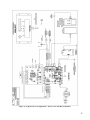
1
I/O ZONE 560/583 USERS GUIDE 641-224 641-242 641-237 1 Table of Contents Hot Gas Re-Heat Valve On/Off:................................. 15 THE ZONE CONTROLLER......................4 Modulating Re-Heat Valve: .......................................... 16 SPECIFICATIONS ................................5 Filter: .............................................................................. 16 CONTROLLER COMPONENTS ...............6 Heating and Cooling – (1 and 2 Compressor Stages): 16 The heating will be enabled whenever:....................... 17 The cooling will be enabled whenever: ...................... 17 LED Indicators ..............................................................6 DIP and Rotary Switches...............................................7 Jumpers and settings......................................................8 LONWORKS® CARD OPTION...............9 WATER TO AIR OPERATION ..............10 Reversing valve:............................................................. 17 Supplemental Electric Heating Stage: ......................... 17 Discharge Air Temperature: ........................................ 18 High Discharge Air Temp:.......................................... 18 Low Discharge Air Temp: .......................................... 18 Discharge Air Sensor Failure:..................................... 18 General Description .......................................................10 Key Features and Benefits.............................................10 Discharge Air Control ................................................... 18 Single Outside Air Temperature (OAT) Reset: .......... 19 Multiple Outside Air Temperature (OAT) Reset: ....... 19 Inputs ..............................................................................11 Outputs............................................................................11 Control & Status Parameters and Alarms...................11 Control.........................................................................11 Status ...........................................................................12 Alarms .........................................................................12 SEQUENCE OF OPERATION ...............13 Run Conditions: .............................................................13 Occupied Mode ...........................................................13 Unoccupied Mode (night setback):..............................13 Zone Temperature .........................................................14 High Zone Temp: ........................................................14 Low Zone Temp: .........................................................14 Zone Sensor Failure: ...................................................14 Zone Setpoint Adjust: ....................................................14 Zone Unoccupied Override: ..........................................14 Freeze Protection: ..........................................................15 Fan:..................................................................................15 Constant Volume.........................................................15 VAV ............................................................................15 Zone Humidity: ..............................................................15 Leaving Water Temperature:....................................... 20 High Leaving Water Temp: ........................................ 20 Low Leaving Water Temp:......................................... 20 Leaving Water Sensor Failure: ................................... 20 WATER TO WATER OPERATION ........ 25 GENERAL DESCRIPTION ................... 27 Inputs .......................................................................... 27 Outputs........................................................................ 27 CONTROL & STATUS PARAMETERS AND ALARMS..................................... 28 Status and Control....................................................... 28 Alarms ........................................................................ 28 SEQUENCE OF OPERATION ............... 29 Run Conditions:............................................................. 29 Occupied Mode........................................................... 29 Unoccupied Mode (night setback): ............................. 29 Auto Changeover Mode.............................................. 29 Digital Input Mode...................................................... 30 BAS Mode .................................................................. 30 Lead - Lag Compressor operation ............................... 31 Compressor 1 Runtime: .............................................. 31 Compressor 2 Runtime: .............................................. 31 2 Pump Control (optional)................................................31 Pump Runtime Alarm:.................................................31 NOTES ........................................................................... 41 Load Water (Entering) Temperature: .........................32 Load High Temp: ........................................................32 Load Low Temp: .........................................................32 Load Sensor Failure: ...................................................32 Source Water (Leaving) Temperature: ........................32 Leaving High Temp: ...................................................32 Leaving Low Temp: ....................................................32 Leaving Sensor Failure:...............................................32 BACview Termination Detail........................................35 RS-Sensor Termination Detail ......................................37 NOTES ................................ Error! Bookmark not defined. 3 The Zone Controller The Zone control board also known as DDC The controller is programmed in the factory and shown in figure 1 is used in most with software versions that suit the different configure to order applications. applications FHP offers. User settings such It is BACnet® native which makes it flexible as the time and test and balance set points and easy to integrate into existing Building shall be set up during the installation and Automation commissioning process at the job site. Systems (BAS). The main difference between the 560 and the I/O 583 is the Analog Output (AO) plug enclosed in figure 1. Figure 1 - Zone Controller Analog plug enclosed in red box on figure above is only available on Zone I/O 583. 4 Specifications Power: 24VAC ± 10%, 50-60Hz, 20VA power consumption (Single Class II 70VA or 100VA option available) Physical: Rugged plastic housing protects circuitry. Environmental Operating Range: 40° to 130°F (-17.8° to 54.4°C); 10 to 90% relative humidity, non-condensing Digital Outputs: Five digital outputs relay contacts rated at 1A resistive @ 24VAC; normally open. configured as dry contact, Universal Inputs: 8 inputs. Inputs 1 and 2 are configurable for 0-5VDC, 10K ohm thermistor, or dry contact; inputs 3 and 4 support thermistor or dry contact only; inputs 5 and 6 support thermistor, dry contact, or LogiStat. Inputs 7 and 8 are used for 1-10K adjustment pots or dry contacts. Standard Communication Ports: Comm Port: 3-pin port configurable for ARC156 (BACnet-over- ARC156) or EIA-485communications (BACnet MS/TP, Modbus RTU, orN2). Rnet Port: 4-pin port for interface with remote mounted BACview6 or RS sensors Local Access Port: For local communication with a laptop computer running WebCTRL or for communication with a BACview6. Status Indication: Visual (LED) status of network communication, running, errors, power, and all digital outputs Battery: Lithium 3V coin cell battery, CR2032, provides a minimum of 10,000 hours of Data retention during power outages Protection: Surge and transient protection circuitry for power and communications. Listed by: FCC Part 15 - Subpart B - Class A. Pending listings at the time of publishing this document: UL 916 (PAZX), cUL C22.2 No. 205-M1983 (PAZX7), CE (1997). Weight: 0.6 lbs. (0.27 Kg). Overall Dimensions: Mounting Hole Dimensions: 5-1/16” (width) by 5-11/16” (height) by 1-1/2” (recommended panel depth). 129mm (width) by 144mm (height) by 38mm (recommended panel depth). Two mounting holes center line as at left with 5-9/16” (141mm) Spacing (height) 5 Controller Components LED Indicators The DDC controller is equipped with three bank sets of LED that help the user diagnose problems and or identify normal operation. The first bank is located in the upper left Figure 2 - Network LEDs hand corner as shown in the figure 2. They flash repeatedly when the controller is communicating with the network and usually service support refers to them as Rx and Tx. The second bank is located on the upper right hand corner of the controller as shown in figure 3. The first one from top to bottom is normally lit (on) while the controller is powered the second is the heart beat and will flash during normal operation, the third Figure 3 - Power LEDs LED will remain off and will lit red in case there is an error in the controller. In addition, when downloading new or modified versions of software these LEDs will flash on and off indicating new files are being written to its non-volatile memory. 6 Figure 4 – Digital Output LEDs The Third Bank of LEDs are located on the bottom right corner of the controller as shown on figure 4 (right) and their purpose is to show the status of individual Digital Outputs (DO) as they are energized DIP and Rotary Switches Figure 5 – Controller Address Rotary DIP switch Two sets of switches can be found on the controllers, they must be set properly to IMPORTANT: allow correct operation of the unit. Controllers must be addressed correctly The first set are rotary switches, as shown in for multiple units to figure 5, is located on the left hand corner work on a network. near the top and their function is to provide the controller address it always convenient Figure 6 – Rotary switches to identify the rotary for the tens and the rotary for the ones as shown in figure 6. The second set is located on the top left hand corner of the controller and it is used for two purposes: (1) SW1 and SW2 set the baud rate of the communications port on the controller: BAUD RATE 9600 19.2K 38.4K 76.8K SW1 Off Off On On SW2 Off On Off On Figure 7 – DIP Switches (2) SW3 supported and SW4 protocols enable on the different controller additional hardware is needed for LonTalk®. 7 Off On Off On Off Off On On IMPORTANT: The LonTalk® card must be installed. Jumpers set up will be Card) is shown in figure 8. 1 Typical DIP switch for LonTalk® (Option ON 2 N2 Modbus Option Card SW4 4 BACnet® MS/TP SW3 3 PROTOCOLS cover under the jumper section. Figure 8 - LonTalk® DIP Settings Jumpers and settings Controllers come equipped with a series of jumpers which allow different types of inputs to be terminated in a particular point. Most inputs allow thermistor or dry contact input devices to be terminated in them, however IN1 and IN2 can be used as analog or digital input points and their available EIA-485 BACnet over ARC156 Figure 9 - Jumper setting for LonTalk® only. options are as follows: 0-5 VDC Analog Input Thermistor Dry Contact FHP sets most switches in the factory, however there are certain cases where a particular sensor is required by the customer, therefore it is important for the installer to understand jumper settings and their relationship with unit configuration and Figure 10 - Jumper Settings operation. Figure 9 shows the location of the jumpers on the controller. 8 LonWorks® card option LonWorks® is a network platform that allows any facility or to integrate sub-systems using a common system architecture and infrastructure. This platform provides fully open operability of the components within a system or sub-system, this enables the facility owner to utilize different vendors and still have the capability of integrating their system into one single server or front end. The LON card option is available for both controllers 641-224 and 641-242. The Lon card connects to the option card port as shown in figure 11. Figure 11 - LonTalk® Card – 641-237 9 Water to Air Operation General Description The Heat Pump Factory mounted I/O Zone 560 or 583 DDC Controllers are factory configured with the Water to Air application program and factory installed in the unit to be job site configureable to run. The unit will operate in a 100% stand-alone control mode or connect to a Building Automation System (BAS) using open protocols BACnet® (ARCNET and MS/TP), Modbus RTU, N2 or LonWorks® (additional network interface board required for LonWorks® option). The point mapping to all of these protocols is available in www.fhp-mfg.com and can be pre-set, so that the protocol and baud rates desired can be easily field-selected and commissioned without the need for any additional downloads or technical assistance. The DDC Controller also supports communications to intelligent RS Room sensors and BACview keypad/display panels. Key Features and Benefits I/O point count: 5 Digital outputs and 6 Universal inputs Powerful high speed microprocessor with 1MB Flash memory and 1MB of battery-backed RAM Built-in protocol support: BACnet® (ARCNET and MS/TP), Modbus, N2 and LonWorks® (additional network interface board required for LonWorks® option) Built-in local access support: BACview6 keyboard/display and Intelligent RS Room sensors On-board lithium battery holds Controller time clock settings Program archived in non-volatile memory allows unit to be ready after long periods of power outages. 10 Inputs RS Room temperature sensor (Rnet) RS Room temperature sensor Set point adjust (Rnet) RS Room temperature sensor Occupancy override (Rnet) Discharge air temperature sensor Leaving water temperature sensor Unit Protection module (UPM) Alarm codes (7 safety shutdown alarms) Unit Filter status (optional) Unit Enable manual control (optional DI Enable) Outputs Unit blower control Reversing Valve Cooling Stage 1 Cooling Stage 2 (Comp 2 Circuit or Comp1 Stage 2) Humidity control output (optional Hot gas re-heat) Auxiliary/Emergency Heating Stage (optional Electric Heat) Control & Status Parameters and Alarms Control BACview occupancy schedule System control: Schedule, Manual ON, BAS command or DI Enable Room temperature occupied cooling/heating set point Room temperature unoccupied cooling/heating set point Unit blower control Reversing valve control Compressor 1 control Compressor 2 control (Comp 2 Circuit) Unit Enable manual control (optional) Humidity Control ( hot gas re-heat optional) Auxiliary/Emergency Electric heat output control (optional) 11 Status Cooling/Heating control status Cooling/Heating percentage (0-100%) Room temperature Discharge air temperature Leaving water temperature Changeover temperature Unit filter status (optional) Fan-Hours runtime counter (filter replacement indicator) Fan starts counter Comp 1 starts counter Comp 2 starts counter (Comp 2 Circuit) Alarms Room temperature high/low differential Leaving water temperature high/low trip Discharge air temperature high/low trip Sensor failure alarm Unit filter Runtime trip (optional) Comp 1 Runtime trip Comp 2 Runtime trip (Comp 2 Circuit) Freeze Stat sensor UPM alarm (optional) Low pressure sensor UPM alarm High pressure sensor UPM alarm Low pressure sensor UPM alarm (Comp 2 Circuit) High pressure sensor UPM alarm (Comp 2 Circuit) Condensate overflow UPM alarm High/low voltage UPM alarm 12 Sequence of Operation Run Conditions: The unit will run according to a user definable time schedule, dry contact (physical digital input number 1), manual ON command from BACview control interface, timed local override from Zone temperature sensor or via third party front end start command (software point). When commanded to run the unit will operate in the following modes: Occupied Mode: The unit will maintain A 74°F (adj.) Cooling setpoint A 70°F (adj.) Heating setpoint Unoccupied Mode (night setback): The unit will maintain A 90°F (adj.) Cooling setpoint. A 55°F (adj.) Heating setpoint. The unit will operate and adjust the setpoints according to the heating and cooling limits which can be changed by the technical agent during the commissioning process if needed. The factory default limits are the following: Occupied Limits: Unoccupied Limits: 75 °F Heating High 70 °F Heating High 60 °F heating Low 50 °F Heating Low 85 °F Cooling High 95 °F Cooling High 65 °F Cooling Low 80 °F Cooling Low IMPORTANT: It is important not to overlap these limits on their respective modes (occupied and unoccupied), overlapping may result in unit cycling between heating and cooling. 13 Zone Temperature The occupant will be able to see the zone temperature on the sensor LCD display in addition the user will be able to see other parameters that have been configured in the controller such as alarm status, alarm codes, Inputs and outputs status among others. NOTE: These codes and values vary from version to version for additional information on what is available on the RS-Pro sensor please check its commissioning BACview manual in our web site www.fhp-mfg.com. Alarms will be provided as follows: High Zone Temp: If the zone temperature is greater than the cooling setpoint plus a user definable amount (adj.), the factory default for this amount is 10. Low Zone Temp: If the zone temperature is less than the heating setpoint minus a user definable amount (adj.) the factory default for this amount is 10. Zone Sensor Failure: If Zone sensor outside of normal operating limits, typically produced by a wire failure between the sensor and the controller. Zone Setpoint Adjust: The occupant will be able to adjust the zone temperature heating and cooling setpoints at the zone sensor (when RS Plus or RS Pro sensors are used). Zone sensor adjustment will allow for +/-5°F of adjustment. If RS Standard sensor is used, then setpoint adjustments must be done at the BACview keyboard/display or through BAS third party control. Zone Unoccupied Override: A timed local override control will allow an occupant to override the schedule and place the unit into an occupied mode for an adjustable period of time (presets at 1-2-4 or 6 hours). At the expiration of this time, control of the unit will automatically return to the software schedule or third party control. 14 Freeze Protection: The unit shall shut down and generate an alarm upon receiving a freezestat status. Fan: Constant Volume In the occupied mode, the fan shall run continuously or cycle with the compressor(s) depending on fan mode settings. In the unoccupied mode, fan cycles as required for unoccupied heating and cooling setpoints while in night setback. Variable Frequency Drive On units equipped with a factory or field installed Variable Frequency Drive (VFD) the controller will command the VFD signal to maintain a particular ( User Definable) value of Static pressure, this is typical on VAV applications with discharge air control requirements. Zone Humidity: If specified the controller has the capability to monitor and control the zone humidity via the hot gas re-heat option. There are two hardware options for humidity control: Hot Gas Re-Heat Valve On/Off: This valve is controlled based on a 60% relative humidity setpoint (User Definable) and will only be energized once the temperature set points are satisfied, this valve is a two position valve and therefore is an on/off operation. Alarms will be provided as follows: High Zone Humidity: If the zone humidity is greater than 75% (adj.). Low Zone Humidity: If the zone humidity is less than 35% (adj.). The controller prioritizes the sensible load and therefore if temperature rises or decreases during the re-heat operation the controller will switch to heating or cooling operation. 15 Modulating Re-Heat Valve: This valve is an analog device and has the capability to modulate the amount of hot gas that is allowed through the re-heat coil, thus allowing control of the discharge air temperature to a user defined setpoint. The operation is similar to the on/off control except once the space temperature is satisfied the controller will monitor the space humidity if the value is greater than the setpoint the controller will modulate the valve to meet a particular a desired discharge air temperature on zone applications only. A typical application of modulating re heat valves can be seen on Discharge Air Control systems where the unit is required to maintain a particular value of supply air temperature (neutral air). For this particular type of units the unit will only discharge air to meet the specific setpoint, this operation is done via a reverse acting PID closed loop, and its sequence of operation is described in detail under the Discharge air section of this document. Filter: Based on fan runtime, a filter alarm message is generated after a user definable amount (adj. factory default 2000 hours) or can be enabled by an optional differential pressure switch. Heating and Cooling – (1 and 2 Compressor Stages): The controller will measure the zone temperature and stage the compressor(s) to maintain its setpoint. To prevent short cycling, there will be a 5 minute delay between compressor stages (if equipped with 2 compressors). Additionally, there will be a 1 minute delay when transitioning between heat and cool modes. The compressor will run subject to internal safeties and controls provided by UPM board. 16 The heating will be enabled whenever: The fan output is on. AND the reversing valve is in heat mode (de-energized). The cooling will be enabled whenever: The fan output is on. AND the reversing valve is in cool mode (energized). Reversing valve: The reversing valve is energized on a call for cooling and will remain energized until a call for heating. Upon a call for heating, the reversing valve is de-energized and remains de-energized until a call for cooling or a call for re-heat on units with humidity (on/off) control option. The compressor will be disabled and remain off for 10sec after the reversing valve has changed position. Alarms will be provided as follows: Compressor 1 Runtime Exceeded: Compressor 1 runtime exceeds a user definable limit (adj.). Compressor 2 Runtime Exceeded: Compressor 2 runtime exceeds a user definable limit (adj.). Supplemental Electric Heating Stage: The controller will measure the zone temperature and stage the heating to maintain its heating setpoint should the compressors not meet the heating demand. To prevent short cycling, the stage will have a 5 minute delay allowing compressor stages to meet the needs of the space. The heating will be enabled whenever: The heat pump is in heating mode. AND the zone temperature is below heating setpoint. AND the fan is on. 17 The controller will only allow supplemental heating if the unit is configured to allow this operation, units equipped with hot gas re heat valves or damper control enable will not have supplemental electric heat functionality. Discharge Air Temperature: The controller will monitor the discharge air temperature to be located at discharge side of coil. If the supplemental heating is installed then sensor will be in the discharge side of heating coil. Alarms will be provided as follows: High Discharge Air Temp: If unit running in cool mode and the discharge air temperature is greater than 70°F (adj.). Low Discharge Air Temp: If unit running in heat mode and the discharge air temperature is less than 75°F (adj.). Discharge Air Sensor Failure: If discharge air sensor outside of normal operating limits. Discharge Air Control On units with factory mounted modulating re-heat valves the controller will operate the unit to maintain a particular discharge temperature setpoint. The discharge air temperature sensor (DATS) will be located at discharge side of coil preferable 3/4 downstream of the total length of the duct work. The controller can operate on single or Multiple Outside Air Temperature Reset, the controller will monitor the value of the Outside Air temperature via a BACnet point or via a physical point terminated in one of the controllers available inputs. The controller will stage the unit’s compressors and modulate the re-heat valve mode to maintain the Discharge Air Setpoint (User adjustable). Two modes are selectable for Discharge Air Control (DAC) Applications are as follows: Single Outside Air Temperature Reset point Multiple Outside Air Temperature Reset points 18 Single Outside Air Temperature (OAT) Reset: OAT> OAT Reset °F (adj.): Controller will initiate cooling call to run compressors and modulate Re-heat Valve only when the outside air temperature is greater than 55°F (Factory Default) OAT< OAT Reset °F (adj.): Controller will initiate a call for heating. Straight cool units will run their fan continuously or if the unit is equipped with a Variable Frequency Drive (VFD) it will command the drive to maintain its static pressure setpoint. Multiple Outside Air Temperature (OAT) Reset: OAT Reset °F < OAT< OAT Reset 2 °F (adj.): Controller will command the unit to run free-cooling operation the fan will run continuously or if the unit is equipped with a Variable Frequency Drive (VFD) it will command the drive to maintain its static pressure setpoint. OAT Reset 2 °F < OAT< OAT Reset 3 °F (adj.): Controller will command the unit to run single stage of cooling operation, the valve will be set for cooling operation and the first compressor will be commanded on, the fan will run continuously or if the unit is equipped with a Variable Frequency Drive (VFD) it will command the drive to maintain its static pressure setpoint and the re-heat valve will be modulated to maintain a 65°F (Factory Default (adj.)) discharge air temperature setpoint . OAT > OAT Reset 3 °F (adj.): 19 Controller will command the unit to run full mechanical cooling operation (on units with more than two compressors please check with factory), the valve will be set for cooling operation and both first and second compressors will be commanded on, the fan will run continuously or if the unit is equipped with a Variable Frequency Drive (VFD) it will command the drive to maintain its static pressure setpoint and the re-heat valve will be modulated to maintain a 65°F (Factory Default (adj.)) discharge air temperature setpoint . Leaving Water Temperature: The controller will monitor the leaving water temperature. Alarms will be provided as follows: High Leaving Water Temp: If compressor(s) is running and the leaving water temperature is greater than 135°F (adj.). Low Leaving Water Temp: If compressor(s) is running and the leaving water temperature is less than 35°F (adj.). Leaving Water Sensor Failure: If leaving water sensor outside of normal operating limits. Should a High or Low Leaving Water Temperature Alarm occur, the call for heat or cool will be removed. UPM Fault Monitor: The controller will monitor the Unit protection Module (UPM) fault input. Upon hard lock out alarm, compressors are disabled by FHP UPM board. Alarms will be provided as follows: HP1: High Pressure Alarm (circuit 1) HP2: High Pressure Alarm (circuit 2) LP1: Low Pressure Alarm (circuit 1) LP2: Low Pressure Alarm (circuit 2) FRE: Freeze Alarm CON: Condensate Alarm BRN: Brownout Alarm 20 Figure 12 - Typical water to air applications – Water to Air Standard 21 Figure 13 -Typical water to air applications – Water to Air with Hot Gas Re-Heat 22 Figure 14 - Typical water to air applications – Water to Air with CO2 and OA Damper 23 Figure 15 – Typical water to air application – Discharge Air Control with Modulating Reheat Valves 24 25 Figure 16 - Typical water to air integration points list 26 Water to Water Operation General Description The Heat Pump Factory mounted I/O Zone 560 or 583 DDC Controllers are factory configured with the Water to Water application program and factory installed in the unit to be job site configurable to run. The Unit will operate in a 100% stand-alone control mode or connect to a Building Automation System (BAS) using open protocols BACnet® (ARCNET and MS/TP), Modbus RTU, N2 or LonWorks® (additional network interface board required for LonWorks® option). The point mapping to these protocols can be pre-set, so that the protocol and baud rates desired can be easily field-selected and commissioned without the need for any additional downloads or technical assistance. The Controller also supports communications to intelligent RS Room sensors and BACview keypad/display panels. Inputs Load (entering) water temperature sensor Leaving (source) water temperature sensor Changeover temperature sensor Cooling/Heating mode select (DI Mode) UPM Alarm codes (7 safety shutdown alarms) Unit Occupancy Enable (DI Enable) Outputs Pump control Reversing Valve Compressor Stage 1 Compressor Stage 2 Aux Output 27 Control & Status Parameters and Alarms Status and Control BACview occupancy schedule System control: Schedule, Manual ON, BAS or DI Enable Load (entering) water temperature Leaving (source) water temperature Changeover temperature (optional) Cooling/Heating control status Cooling/Heating percentage (0-100%) Heating/Cooling mode manual control (optional) Reversing valve control Pump control (optional) Comp 1 control Comp 2 control (Comp 2 Circuit) Alarms Load (entering) water temperature high/low limits Leaving (source) water temperature high/low limits Sensors failure alarm Comp 1 Runtime trip Comp 2 Runtime trip (Comp 2 Circuit) Freeze Stat sensor UPM alarm (optional) Low pressure sensor UPM alarm High pressure sensor UPM alarm Low pressure sensor UPM alarm (Comp 2 Circuit) High pressure sensor UPM alarm (Comp 2 Circuit) Condensate overflow UPM alarm High/low voltage UPM alarm 28 Sequence of Operation Run Conditions: The unit will run according to a user definable time schedule, dry contact (physical digital input number 1), manual ON command from BACview control interface or via third party front end start command (BV software point). When commanded to run the unit will operate in the following modes: Occupied Mode: The unit will maintain A 54°F (12°C) adj. Cooling setpoint A 105°F (40 °C) adj. Heating setpoint Unoccupied Mode (night setback): The unit will maintain A 74°F (12°C) adj. Cooling setpoint. A 85°F (30°C) adj. Heating setpoint. The values above can be changed by the commissioning agent by using the BACview or via the BAS. Auto Changeover Mode When operating on Changeover mode the unit will automatically change from heat to cool and vice versa, by using the Changeover Setpoint and the Changeover Deadband. These points can be changed by the commissioning agent, the factory defaults are 65°F and 3°F (18°C and 2°C) respectively, the units will enter in cooling or heating mode according to the following: 29 Auto Cool: Chageover Temperature > Changeover Setpoint + Change over dead Band Auto Heat: Chageover Temperature < Changeover Setpoint - Change over dead Band When using the changeover feature the system will require an air temperature sensor (10KΩ @ 77°F (25°C) Thermistor) typically located in the controlled zone. Digital Input Mode When operating on Digital Input mode the unit will change from heat to cool and by using the state of the digital input (IN6) on controller as follows: Off = Heat On = Cool This feature is typically used when a remote switch is needed but no BAS is available, if a BAS is available FHP recommends operating the unit by using the integration points as they will provide additional and valuable information the end user. BAS Mode When operating on BAS mode the unit will change from heat to cool and by writing to the Control Mode integration point. Please refer to the integration points list for additional information on how to make the unit part of the BAS. 30 Lead - Lag Compressor operation NOTE: This feature is only available on two stage systems. The unit will alternate the compressors by using Lead Lag control algorithm; the rotation method is user definable and can be set during the commissioning process as follows: Monthly Daily Time of Day By default the unit will change its lead compressor if the one acting as lead fails. The unit will provide the following compressor alarms: Compressor 1 Runtime: If the compressor runtime hours are greater than 8760. Compressor 2 Runtime: If the compressor runtime hours are greater than 8760. Pump Control (optional) The unit can control a pump by using Digital Output 1 (DO1) on controller; this feature can be enable or disabled, set to run with compressors or continuously during the commissioning process. If commissioned to run continuously the pump will run when the unit is in occupied mode. If commissioned to cycle with compressors the pump will be commanded on only when the compressors are running. The factory default is enabled to cycle with compressors. The unit will provide the following compressor alarms: Pump Runtime Alarm: If the pump runtime hours are greater than 8760. 31 Load Water (Entering) Temperature: The controller will monitor the entering load water temperature which is located at entering side of coil. Alarms will be provided as follows: Load High Temp: If the water temperature at the entering load side is greater than the cooling setpoint plus a user definable amount (adj.), the factory default for this amount is 10°F. Load Low Temp: If the water temperature at the entering load side is less than the heating setpoint minus a user definable amount (adj.) the factory default for this amount is 10°F. Load Sensor Failure: If the load water sensor is outside of normal operating limits, typically produced by a wiring failure between the sensor and the controller. Source Water (Leaving) Temperature: The controller will monitor the leaving water temperature on the source which is located on the source leaving side of coil. Alarms will be provided as follows: Leaving High Temp: If the leaving water temperature is greater than 135°F Leaving Low Temp: If the leaving water is less than 35°F. Leaving Sensor Failure: If leaving water sensor is outside of normal operating limits, typically produced by a wiring failure between the sensor and the controller 32 Figure 17 - Typical water to water applications – Water to Water Standard 33 34 Figure 18 - Typical water to water integration points list 35 BACview Termination Detail 36 RS-Sensor Termination Detail The RS Sensor is remotely mounted and installed (up to 500ft) in the zone it is recommended to use shielded cable (20AWG conductors) if installing RS-sensor only. If BACview is installed remotely using the same cable is recommended to use shielded cable (18AWG conductors). Room Sensor DDC - Unit Rnet port termination: Black White Blue Red = Ground = R-net + = R-net =12VDC Field installed wiring four conductor shielded cable 37 The RS-Pro Sensor interface The RS-Pro sensor factory part number 641-230 is a combination keypad/display unit that attaches to a control module to let you view and change temperature and set points values and the controller’s components status, the following features only apply to the software version covered on this manual. ICONS Alarm Bell Indicates Alarm Condition (see INFO button for more information) Cooling Indicates unit enabled in cooling mode Heating Indicates unit enabled in heating mode Occupied Indicates unit in occupied mode Unoccupied Indicates unit in unoccupied mode Fan Indicates fan output energized BUTTONS ANUAL ON Places unit into occupied mode. Allows for incremental increase in override time ( 60min, 120min, 180 min , 4hrs, 5hrs, 6hrs, 0 min) each time button is pressed WARMER Allows for increase in zone temperature setpoint (+1° to per push to a maximum of +5° or as configured at DDC through BAC view6) from default setpoint value COOLER Allows for decrease in zone temperature setpoint (-1° to per push to a maximum of -5° or as configured at DDC through BAC view6) from default setpoint value. 38 IMPORTANT: INFO By Pressing the Info button on the sensor the user can see the following typical data: PRESS 1 – Displays occupancy override time (in minutes) PRESS 2 – Displays actual heating setpoint (in degrees F) PRESS 3 – Displays actual cooling setpoint (in degrees F) PRESS 4 – [ 1 ] - Displays discharge air temperature (in degrees F) PRESS 5 – [ 2 ] - Displays leaving water temperature (in degrees F) PRESS 6 – [ 3 ] - Displays active alarm code 0 Indicates NO ALARM 1 Indicates active HP alarm comp 1 2 Indicates active LP alarm comp 1 3 Indicates active HP alarm comp 2 4 Indicates active LP alarm comp 2 5 Indicates active freezestat alarm 6 Indicates active condensate alarm 7 Indicates brownout condition 20 Indicates input/out in MANUAL lock position. It is not in AUTO 30 Indicates RS zone, discharge or leaving water temperature sensor failure 40 Indicates high or low RS zone temperature condition 50 Indicates high or low discharge air temperature condition 60 Indicates filter or compressor service alarm 70 Indicates high or low leaving water temperature condition PRESS 7 – [ 1 ] – Displays status of compressor 1 output (ON/OF) PRESS 8 – [ 2 ] – Displays status of compressor 2 output (ON/OF) PRESS 9 – [ 3 ] – Displays status of auxiliary heat output (ON/OF) PRESS 10 – Displays fan status (fan icon=fan ON), unit condition (AU=auto) PRESS 11 – Displays unit mode (AU=auto) PRESS 12 – Goes back to default screen display 39 NOTES 40 NOTES 41 601 N.W. 65th Court, Ft. Lauderdale, FL 33309 Phone: 954-776-5471 Fax: 954-776-5529 www.fhp-mfg.com 970-443 REV. 6-11 42