1
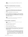
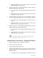
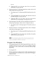
SmartWindows4
installation guide
© 2005 Directed Electronics, Vista, CA N903010 10-05
IMPORTANT! Please note that this manual was intended for US consumers
and therefore includes American phrases or words.
Bitwriter™, Code Hopping™, Directed®, Doubleguard®, ESP™, FailSafe®, Ghost Switch™, Learn Routine™, NiteLite®, Nuisance Prevention® Circuitry, NPC®, Revenger®, Silent Mode™, Soft Chirp®, Stinger®, Valet®, Vehicle
Recovery System®, VRS®, and Warn Away® are all Trademarks or Registered Trademarks of Directed Electronics,
Vista, California.
2
www.directed.com
contents
warning! safety first . . . . . . . . . . .5
wiring reference section . . . . . . .10
install the smartwindows 4 acces-
tips for adding smartwindows4
sory . . . . . . . . . . . . . . . . . . . . . . . . .5
to systems . . . . . . . . . . . . . . . . . . .12
motor/switch connections . . . . . . .5
notes . . . . . . . . . . . . . . . . . . . . . . .15
..
Motor/Switch Connections Negative Switches . . . . . . . . . . . . .6
Program the Windows . . . . . . . . .7
window control . . . . . . . . . . . . . . .8
section 1—automatic . . . . . . . . . .
window/sunroof closure . . . . . .8
section 2—window rollup . . . . .9
© 2005 directed electronics—all rights reserved
3
4
www.directed.com
NOTE: If you can close the vehicle’s windows by turning the key in the door,
SmartWindows 4 will not operate properly. Refer to the “Window Control” section of
this manual.
install the smartwindows 4 accessory
NOTE: Refer to the Wiring Quick Reference Diagram at the back of this manual for
the following instructions.
1.
Connect one end of the CliffNet Dataport Interconnect cable to the alarm
system control unit and connect the other end into the SmartWindows 4
module.
2.
Connect the 14AWG BLACK wire to the chassis ground.
3.
Connect the 14AWG RED wire from the pigtail to a 30 amp fuse at the battery
positive cable clamp, connect the 18AWG RED wire to a 5 amp fuse at the
battery positive cable clamp. Connect 18AWG BLACK wire to the battery
negative battery cable clamp.
NOTE: For one touch operation on the passenger switch, connect between the passenger switch and the window motor. For normal passenger switch operation, connect anywhere between the driver and passenger switches.
motor/switch connections
NOTE: Refer to the Wiring Quick Reference Diagram at the back of this manual for
the following instructions.
1.
Turn the ignition switch to the “ON” position.
2.
Access the wires at the window motor.
3.
Connect the negative voltmeter lead to ground.
4.
Connect the other voltmeter lead to a wire at the driver’s side window motor and
find the wire that shows 12V while pressing the driver’s window switch as if
rolling the window up.
a.
If the voltmeter reads 12 volts while pressing the “UP” side of the switch,
cut this wire. (If you do not get a 12V reading while rolling the windows
up, then connect (-) lead of the voltmeter to +12V and probe the window
wires. If you find a wire that shows +12V while rolling the window
up/down, go to the Motor/Switch Connections - Negative Switches section
below.)
© 2005 directed electronics—all rights reserved
5
b.
5.
6.
7.
Connect the ORANGE wire to the motor side of the cut wire and the
WHITE/ORANGE wire to the switch side.
Find the wire that shows 12V while pressing the driver’s window switch as if
rolling the window down on the driver’s side.
a.
If the voltmeter reads 12 volts while pressing DOWN side of the switch, cut
this wire.
b.
Connect the BLUE wire to the window motor side of the cut line and the
WHITE/BLUE wire to the switch side.
Go to the passenger’s side window switch wires and find the wire that shows
12V while pressing the passenger’s window switch as if rolling the window up.
a.
If the voltmeter reads 12V while pressing the “UP” side of the switch, cut
this wire.
b.
Connect the VIOLET wire to the motor side of the switch and the
WHITE/VIOLET wire to the passenger ’s switch side.
Find the wire that shows 12V while pressing the passenger window switch as if
rolling the window down on the passenger window.
a.
If the voltmeter reads 12 volts while pressing DOWN side of the switch, cut
this wire.
b.
Connect the GRAY wire to the window motor side of the cut line and the
WHITE/GRAY wire to the switch side.
NOTE: If the vehicle has power window switches only on the center console (no door
switches), you may make the appropriate connections at the switch. If there are door
switches, you must make the connections at each motor.
Motor/Switch Connections - Negative Switches
1.
Make sure the ignition switch is turned to the “ON” position.
2.
Access the wires at the window motor.
3.
Connect the negative voltmeter lead to 12V.
4.
Connect the other voltmeter lead to a wire at the driver’s side window motor and
find the wire that shows 12V while pressing the driver’s window switch as if
rolling the window up.
a.
6
If the voltmeter reads 12V while pressing the “UP” side of the switch, cut
www.directed.com
this wire.
b.
5.
6.
Find the wire that shows 12V while pressing the driver’s window switch as if roll
ing the window down on the driver’s side.
a.
If the voltmeter reads 12V while pressing DOWN side of the switch, cut this
wire.
b.
Connect the ORANGE wire to the window motor side of the cut line and
the WHITE/ORANGE wire to the switch side.
b.
Connect the GRAY wire to the motor side of the switch and the
WHITE/GRAY wire to the passenger’s switch side of the cut line.
Go to the passenger’s side window switch wires and find the wire that shows 12v
while pressing the passenger’s window switch as if rolling the window up.
a.
7.
Connect the BLUE wire to the motor side of the cut wire and the
WHITE/BLUE wire to the switch side.
If the voltmeter reads 12V while pressing the “UP” side of the switch, cut
this wire.
Find the wire that shows 12V while pressing the window switch as if rolling the
window down on the passenger’s window.
a.
If the voltmeter reads 12V while pressing DOWN side of the switch, cut this
wire.
b.
Connect the VIOLET wire to the window motor side of the cut line and the
WHITE/VIOLET wire to the switch side.
NOTE: If the vehicle has power window switches only on the center console (no door
switches), you may make the appropriate connections at the switch. If there are door
switches, you must make the connections at each motor.
Program the Windows
1.
Use the programming grid in the Installer-Programmable Features section in the
installation manual for the security system you are installing to program
SmartWindows 4. Make sure both windows are rolled down before you begin
programming.
2.
Turn the ignition ON.
3.
Select the appropriate row/column from the installer programming grid, the
siren will chirp twice. Press and hold the driver’s window switch “UP” for approximately two seconds.
© 2005 directed electronics—all rights reserved
7
4.
Release the switch and allow the window to roll up. After the window reaches
the top, it will pause. It will then automatically complete programming by rolling
both windows up/down several times.
5.
Programming is complete when both windows vent. You may then turn off the
key to exit programming or if you have a second set of SmartWindows 4
installed, touch and release the driver’s window UP for the second set of
windows. It will follow the same process as the first set you programmed. If the
programming doesn’t complete successfully, start over from step #1.
Memory is nonvolatile and will NOT have to be reprogrammed in the event of a
power loss.
To fine tune the vent or to program the windows without using the valet switch, use the
CliffNet Wizard Pro.
window control
If the windows can be closed using a key in the door of the car, see section 1 below.
If the windows cannot be closed using a key in the door and the alarm you are
installing has built-in window roll up, see section 2 below.
section 1—automatic window/sunroof closure
NOTE: This requires the use of an optional relay.
If the door key can close the power windows/sunroof, you can make them automatically close upon remote arming.
1.
Find the wire that shows either +12V or (-) when the key is held at the lock
position in the door cylinder.
2.
Tap a wire in to this wire and connect to terminal 30 of the optional relay.
3.
If the wire shows (-) when the key is turned, connect terminal 87 to (-). If the wire
shows +12V when the key is turned, connect terminal 87 to 12V.
4.
Connect the output of the alarm that can be set to AutoActivate to terminal 85.
5.
Connect +12V to terminal 86.
6.
Turn on the “AutoActivate timed accessory upon remote arming” feature as
noted in the installation manual for the alarm under the Programmable Features
section.
8
www.directed.com
7.
Set the timer duration to proper time interval with 2-seconds added to that time
interval.
section 2—window rollup
NOTE: This may require the use of an optional relay(s).
The instructions in this section apply to systems with the built-in window roll up feature. If the windows can be closed using a key in the door of the car, see section 1
above.
motor/switch connections
1.
Turn the ignition switch to the “ON” position.
2.
Access the wires at the window switch.
3.
Connect a voltmeter lead to ground.
4.
Connect the other voltmeter lead to a wire at the window switch and find the wire
that shows 12V while pressing the window switch as if rolling the windows up.
a.
5.
If the voltmeter reads 12V while pressing the “UP” side of the switch, make
the connections as shown in diagram A, otherwise proceed to step 5.
Connect the (-) voltmeter lead to +12V and probe the UP wire without activating
the switch.
a.
If the voltmeter reads 12V, make the connections as shown in diagram B.
b.
If the voltmeter reads 0V, make the connections as shown in diagram C.
NOTE: If the vehicle has power window switches only on the center console (no door
switches), you may make the appropriate connections at the console switch. If there
are door switches, it is recommended that you make the connections at each door
window motor.
If the vehicle has relay-driven motors, or one-touch switching, the connections must be
made after the controlling relay or module.
programming the windows
Use the installer programming section in the security installation manual to program
window roll ups.
© 2005 directed electronics—all rights reserved
9
wiring reference section
window control—wiring tips
10
www.directed.com
quick wiring reference diagram—window control
© 2005 directed electronics—all rights reserved
11
tips for adding smartwindows4 to systems
This section will assist when installing SmartWindows 4 with any of the following listed systems. If doing so, it will be necessary to use the CliffNet Wizard Prosoftware.
AvantGuard 4
Concept 600
IntelliGuard 9000
or IntelliGuard Millennia
If using SmartWindows4 WITH the system’s window rollup electronics:
control the rear windows. When installation is complete:
1.
Plug the Wizard cable into any available 3-pin DataPort connection in the installation (on SmartWindows 4, for example).
2.
Launch the CliffNet Wizard PRO program.
3.
Click the Install icon button at the top of the screen.
4.
Turn ignition on and roll down all windows.
5.
Make sure the check box next to the Program Windows button indicates
enabled, then click the Program Windows button. The rear windows (connected
to the built-in window roll-up electronics) will close.
6.
Once the rear windows reach the top, wait 20 seconds, then click OK.
7.
Click the Windows icon button at the top of the screen.
8.
Click the Enter Program Mode button.
9.
Hold one of the front window switches “up” for about 2 seconds, then release
(the switch must be connected to SmartWindows 4). The window should move
immediately when you hit the switch.
10. Allow the windows to finish the programming cycle. This should take about 2
minutes and is indicated as complete when both windows vent slightly.
a.
12
If you have another SmartWindows 4 to program, select ID2 from scroll
bar at top and repeat steps 7-10.
www.directed.com
11. Click done.
12. Click OK to save and exit or Apply to save and test/adjust vent duration.
If using SmartWindows 4 INSTEAD OF the system’s window rollup electronics:
Install the SmartWindows 4 module(s). When installation is complete:
1.
Plug the Wizard cable into any available 3-pin DataPort connection in the installation (on SmartWindows 4, for example).
2.
Launch the CliffNet Wizard PRO program.
3.
Click the Install icon button at the top of the screen.
4.
Make sure the check box next to the Program Windows button indicates
disabled, then click the Program Windows button. This will disable the system’s
built-in window roll-up electronics. If you do not do this, there will be a 7-second
delay after arming until SmartWindows 4 activates.
5.
Click OK.
6.
Click the Windows icon button at the top of the screen.
7.
Turn ignition on and roll down all windows.
8.
Click the Enter Program Mode button.
9.
Hold one of the window switches “up” for about 2 seconds, then release (the
switch must be connected to SmartWindows 4). The window should move
immediately when you hit the switch.
10. Allow the windows to finish their programming cycle. This should take about 2
minutes and is indicated as complete when both windows vent slightly.
11. If you have another SmartWindows 4 to program, select ID2 from scroll bar at
top and repeat steps #7-11. Otherwise, go to next step.
12. Click done.
13. Click OK to save and exit or Apply to save and test/adjust vent duration.
© 2005 directed electronics—all rights reserved
13
14
www.directed.com
notes
________________________________________
________________________________________
________________________________________
________________________________________
________________________________________
________________________________________
________________________________________
________________________________________
________________________________________
________________________________________
________________________________________
________________________________________
________________________________________
________________________________________
________________________________________
________________________________________
________________________________________
________________________________________
________________________________________
________________________________________
________________________________________
________________________________________
________________________________________
________________________________________
________________________________________
________________________________________
________________________________________
© 2005 directed electronics—all rights reserved
15