1
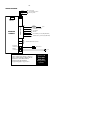
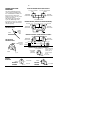
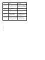
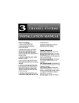
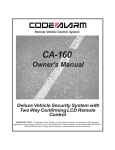
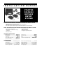
I N S TA L L AT I O N
M A N U A L
STARTER
DISABLE/
KEYLESS
ENTRY
SYSTEM
BEFORE INSTALLING THE STARTER DISABLE/KEYLESS ENTRY SYSTEM
• DO read through this installation manual.
• DO NOT install the control module in an engine compartment.
• The alarm may arm itself when power is first connected.This is a normal condition.
ITEMS SUPPLIED WITH THE STARTER DISABLE/KEYLESS ENTRY SYSTEM
• Receiver and control module
• Two 2-Button or 3-button, code learning
transmitters
• Door lock harness
• Valet/override switch
• LED status indicator
• Wiring harness, fuseholder, & fuse
OPTIONAL ACCESSORIES
Backup battery...............................................BWS-500
Remote starter ..............................................RAS-101
Trunk release .....................................................TR-100
Starter disable relay socket.........................BRS-003
(+) door lock Inverter..............................BW-34516
Window roll up...........................................................WRM-2
Power door lock.........................................................PDL-50
Relay ....................................................................................SPDT
5-wire door lock relay & socket ...............BRS-008P16
SPECIFICATIONS
Operating voltage..................+12 VDC Neg. Ground
Code learning..........................................3 Codes Max.
Current consumption............5 mA (max) disarmed.
Door lock/unlock output .........................(-) 500 mA.
Channel 2 output drive.............(-) 500 mA variable.
Remote control transmit frequency.......................310 mHz.
Passive arming delay..................................30 Seconds approx.
Auxiliary output drive ...............................250 mA maximum.
Flashing output drive .................................(-) 250 mA 30 sec.
Dome light output......................................(-) 250 mA 30 sec.
-1INSTALLATION INSTRUCTIONS
IMPORTANT: Make all wiring connections to the vehicle before connecting the main
6-pin harness and all plug-in connectors to the receiver control module.
1. Before mounting the Control Module, you must set the PROGRAMMING DIPSWITCHES for the kind of
operation the customer wants.
These are the switch settings available; Standard (Default) settings are in “BOLD” type:
Switch #1 Door Lock and Unlock Pulse Time: ON = 3/4 seconds. OFF = 3 seconds.
Switch #2 Door Lock and Unlock with ignition: ON = YES. OFF = NO.
Switch #3 Passive Door Locks. ON= YES. OFF= NO
Switch #4 Passive Arming. ON= YES. OFF= NO
2. Mount the Receiver and Control Module in a secure area, away from vehicle computers and heating/air conditioning ducts.The location should be convenient for your installation, but well hidden from thieves.Try to mount the unit
as far away from metal objects as possible.This will increase the range of its Remote Control Transmitter.
3. Route the wires of the harnesses to areas in which the different accessories will be mounted.You may need
to extend some wires. DO NOT plug the wiring harnesses into the Receiver Control Module until all
connections have been completed.
When running the harness wires through the vehicle, be careful to run them where they CANNOT be DAMAGED or SHORTED to GROUND or other WIRING. Keep them away from ALL MOVING PARTS of the vehicle
or where HIGH HEAT can damage their insulation.Always protect the harness wires where they pass through
holes in metal panels by using RUBBER GROMMETS.
4.Mount the LED Status Indicator in an easily seen location such as the center of the dash or the inside top
edge of the driver’s or passenger’s door. Connect the RED 2-pin connector from the LED to the RED
2-pin male plug on the circuit board of the Receiver Control Module.
7. Install the Valet/Override Switch in a hidden location that is easily reached by the driver. Remember that
the code learning and valet/override sequence require using this switch in conjunction with the ignition switch, so it
should be hidden, but convenient to use when needed. Connect the BLUE 2-pin connector from the Override
Switch to the BLUE 2-pin male plug on the circuit board of the Receiver Control Module.
8. Find the Starter wire and cut in half , connect to the BROWN wires.
9. Mount and connect any optional function modules included in the installation, following the mounting and
wiring directions supplied with them.
10. Complete the general wiring of the main harness by connecting...
A.The RED wire to CONSTANT +12vdc. IMPORTANT: Remove the fuse from the harness before connection.
B. Connect BROWN wire to siren or horn.
C.The YELLOW wire to a source of TRUE IGNITION (must not drop while starting).
D.The BLACK wire to a good chassis GROUND point.
E.The GRAY wire connects to 2nd. channel output (relay required), i.e. trunk release, remote autostart, etc.
F.The WHITE wire to the vehicle’s PARKING/DOME LIGHT circuit. See the Circuit Diagram on Page 5.
-211. Connect the Main 6-Pin Wiring Harness and all pin connectors to the Control Module. Install the fuse
in the RED wire of the main wiring harness.
13. Code Learning Procedure:
To add a new remote to the system, turn ignition key ON, OFF, ON, OFF, and leave on (3 times). Siren/Horn
will chirp once. Press override/valet switch for 5 seconds, you will hear 3 chirps. You now have 5 seconds to press
the arm buttons on the remotes that you want to operate the system. It will hold 3 different codes in memory
and will erase all previous codes. You will get a confirming chirp after it has learned each new remote.
14. Test Starter Disable Feature by:
A. Pressing button#1, LED will flash slowly and Starter Disable will be activated.You should not be able to
start the engine while the Starter Disable is engaged. Once all testing is complete, secure all loose wiring and/or
components and reassemble the vehicle.
15.To activate Override Feature with Starter Disable activated, turn the ignition switch ON, press override switch for 5 seconds, the LED will turn ON solid. Start your vehicle in normal operation.
16 . The Status Indicators below, show the various signals that are produced to indicate a particular condition
or situation of the Starter Disable/Keyless Entry System:
PARKING LIGHTS STATUS
A)1 Flash = Starter Disable ON/Door lock
B) 2 Flashes = Starter Disable OFF/Door unlock
C) 30 sec. Flashing Lights= Starter Disable OFF
or vehicle unlocked
LED STATUS
A) No Flash = Starter Disable OFF/Unlocked vehicle
B) Steady Flash = Starter Disable ON/Doors locked
C) Rapid Flash= Passive prearm mode
D) Solid = Valet Mode
17. Siren/Horn Pulsing Output
To enable pulsing horn output, with the ignition key ON, push button #3 on 3 button remote (push buttons #1 and
#2 simultaneously on 2 button remote), LED will flash twice. Pulsing horn output is activated.
Disable horn output– Enables siren output, with the ignition key ON, push button #3 on 3 button remote (push
buttons #1 and #2 simultaneously on 2 button remote), LED will flash once. Steady siren/horn output is activated.
18. Current Sensing Loop. Cut the Brown loop (current sensing is disabled from the factory).When the door is
opened, if the dome light is ON and the light bulb is strong enough, it will sense current and trigger the alarm.
-3-
CONNECTOR PIN NUMBERS AND WIRE COLOR CODES
6 PIN HARNESS
PIN
1)
Wire Color
Red
Function
Main Power hook to constant 12v+ source
2)
Brown
Negative Output for siren or car horn
3)
Yellow
Ignition Input 12v+ (must not drop out while
starting)
4)
Black
Ground
5)
Gray
2nd Channel Output (negative output)
6)
White
Parking Light/Dome Light Output (negative
output). Requires 2 relays for both outputs.
3 PIN PLUG IN HARNESS
1)
Yellow
2)
Red
3)
Green/Black
Unlock Pulse (negative output)
Constant 12V+ output
Lock Pulse (negative output)
2 PIN OVERRIDE/VALET (BLUE) PLUG IN HARNESS
1)
Blue Plug
Plug for override/ valet switch
2 PIN LED (RED) PLUG IN HARNESS
1)
Red Plug
Plug for LED/Status Indicator
PLUG IN STARTER CONNECTORS
1)
Brown
Cut starter wire connect to starter side
2)
Brown
Cut starter wire connect to ignition side
-4-
WIRING DIAGRAM
LOCK (-) PULSE
GREEN
+12V CONSTANT OUTPUT
RED
UNLOCK (-) PULSE
BLUE
1 2 3 4
DIPSWITCH
(INSIDE OF
MODULE)
FUSE
RED
WIRING HARNESS
RECEIVER
MODULE
(+)12V
BROWN
HORN/SIREN (-) OUTPUT
YELLOW
BLACK
12V IGNITION
GROUND
GRAY
2nd CHANNEL (-) OUTPUT (REQUIRES RELAY)
WHITE
}
PARKING LIGHT (-)OUTPUT (REQUIRES RELAY)
STARTER DISABLE INPUT/OUTPUTS
BLUE VALET
CONNECTOR
VALET SWITCH
RED LED
CONNECTOR
DIP
SWITCH
LED
PROGRAMS:
(1) Door lock/unlock pulse ON=.75 sec. OFF= 3 sec.
(2) Door lock/unlock w/ignition. ON=Yes. OFF= No.
(3) Passive Door Locks. ON=Yes. OFF=No.
(4) Passive Arming. ON=Yes. OFF=No.
See programming specifics on page 2, Section 1.
Ignition +12V
MUST NOT
DROP OUT
during starting
of vehicle.
-5-
POWER DOOR LOCK
DIAGRAMS:
POSITIVE TRIGGER DOOR LOCK CIRCUIT*:
TO DOOR LOCK RELAY
The Starter Disable/Keyless Entry
comes equipped to handle ground
door lock installations.The Blue and
Green wires from the Receiver
Module are ready to tap into grounding door lock systems.
The following door lock diagrams
require two SPDT Relays or the
appropriate accessories not included
with the system.These items must be
ordered separately.
TO DOOR UNLOCK RELAY
LOCK
GREEN WIRE
FROM ALARM
UNLOCK
87
87a
86 85
30
87
87a
86
30
BLUE WIRE
FROM ALARM
85
12 V FUSED CONSTANT
REVERSE POLARITY (DIRECTLY TO AD-ON ACTUATORS)✝:
GROUND
GROUND
87
87
GREEN WIRE
FROM ALARM
FOR NEGATIVE
PARKING LIGHTS
86
87a
86 85
30
87a
85
30
BLUE WIRE
FROM ALARM
12 V FUSED CONSTANT
VEHICLE
PARKING
LIGHT
WIRE
WHITE
REVERSE POLARITY USING FACTORY SYSTEMS✝:
LOCK
UNLOCK
87
GREEN WIRE
FROM ALARM
FOR POSITIVE
PARKING LIGHTS
87
87a
86
85
30
86
87a
30
SWITCH
TO VEHICLE
PARKING LIGHT
CIRCUIT
X CUT X
LOCK
87
87a
86 85
30
85
12 V FUSED
CONSTANT
UNLOCK
BLUE WIRE
FROM ALARM
ACTUATOR
X CUT X
TRUNK RELEASE CIRCUIT DIAGRAM:
OUT TO TRUNK 12V
If the power trunk
release requires a
87
2nd CHANNEL
positive pulse to
87a
AUXILIARY
86
85
operate, use this
(GRAY WIRE)
30
circuit.
WHITE
(+) 12V
12V POSITIVE
DOME LIGHT
CIRCUIT
DIAGRAM:
TO (-) DOME LIGHT SWITCH
TO (+) DOME LIGHT SWITCH
87
WHITE
NEGATIVE
TRIGGER
87a
86
85
30
12V POSITIVE
GROUND
WHITE
POSITIVE
TRIGGER
87
87a
86
85
30
12V POSITIVE
PROBABLE
CAUSE
SUGGESTED
CORRECTION
Keyless will not go
into Code Learning
Mode
RED or YELLOW wire not connected
to the correct power source. Code
Learning sequence done to slow.
RED wire should connect directly to
the battery. Connect YELLOW wire to
true ignition wire (Not at Fuse Block).
Redo Code Learning sequence faster.
Remote Control does
not lock and unlock
the vehicle.
Defective Remote Control. Bad
battery. Antenna wire is
grounded.
Replace Remote Control or its
battery. Unground antenna.
Override does not work.
Bad switch or switch is not pressed
long enough to activate the Keyless
Entry
Repair or replace switch or check
ignition wire for voltage.
Flashing output does
not work.
Bad connection on WHITE
wire or the drive polarity is
wrong for the circuit being
driven.
Check WHITE wire. Connect
a SPDT Relay to this wire and
apply the opposite polarity to the
circuit being driven.
Door locks do not
lock/unlock correctly,
or action is reversed.
Defective GREEN or BLUE
wire from door lock connector plug,
GREEN and BLUE wires on door lock
connector plug reversed, or wrong
door lock wiring diagram used.
Check GREEN and BLUE wires
on door lock connector plug.
Check vehicle’s door lock
system for method of operation.
Reverse wiring to door relays.
752/1/L
Rev.7 091997
SYMPTOM