1
Apolloâ
Model GX50 GPS
Model GX60 GPS/Comm
Model GX65 GPS/Comm
February 2002
560-0959-04
ã 2002 by II Morrow Inc (UPS Aviation Technologies, Inc.). All rights reserved.
Printed in the USA
No part of this document may be transmitted, reproduced, or copied in any form or by any means
without the prior written consent of II Morrow Inc. Due to II Morrow’s commitment to
constantly improve the quality and performance of our products, information contained in this
document is subject to change without notice.
UPS Aviation Technologies, II Morrow, Apollo, and Flybrary are registered trademarks of
II Morrow Inc.
II Morrow Inc. (UPS Aviation Technologies, Inc.)
PO Box 13549
Salem, OR 97309
Phone (503) 581-8101
1-800-525-6726
In Canada 1-800-654-3415
FAX (503) 364-2138
2345 Turner Rd. SE
Salem, OR 97302
USA
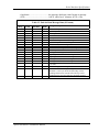
HISTORY OF REVISIONS
Revision SW Ver
Date
-Nov 5, 1997
-01
Nov 11, 1997
-01b
June 10, 1998
-02
-03
-03a
-03b
-03c
-04
3.3
Description
Initial release.
Corrected altitude input requirements.
Added references about altitude encoders, F/AD, & serial
interface
June 26, 1998 Addition of Model GX65 GPS/Comm
Mar 24, 1999 Test Mode additions, Serial data output, Apollo ACU added
Sept. 23, 1999 Added new connector pins and crimping tools
5/8/00
Add new extended data and SL30 output messages
7/2/01
Add autopilot roll steering data, and changes for GX SW
Ver 3.3. Mounting tube changes.
2/18/02
Added helicopter environmental qualification information
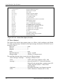
IMPORTANT NOTE
“The conditions and tests required for TSO approval of this article are minimum performance
standards. It is the responsibility of those desiring to install this article on or within a specific
type or class of aircraft to determine that the aircraft operating conditions are within TSO
standards. The article may be installed only if further evaluation by the applicant documents
an acceptable installation and is approved by the Administrator.”
Source: FAA TSO-C129a, TSO-C37d, TSO-C38d, and TSO-C128
ORDERING INFORMATION
To receive additional copies of this publication, order part # 560-0959-04, Apollo GX50 GPS
and GX60/GX65 GPS/Comm Installation Manual.
NOTES
Table of Contents
TABLE OF CONTENTS
SECTION 1 - INTRODUCTION ................................................................................................ 1
ABOUT THIS MANUAL ..................................................................................................................... 1
APOLLO GX50/60/65 DESCRIPTION ................................................................................................. 1
FEATURES ........................................................................................................................................ 3
SYSTEM CONFIGURATIONS ............................................................................................................... 4
VFR GPS NAVIGATION INSTALLATION .....................................................................................................................4
IFR GPS NAVIGATION INSTALLATION ......................................................................................................................5
COMM TRANSCEIVER - GX60/65...............................................................................................................................5
DATABASE UPDATES........................................................................................................................ 5
REGULATORY COMPLIANCE ............................................................................................................. 5
UNPACKING THE EQUIPMENT ........................................................................................................... 6
PACKAGE CONTENTS ....................................................................................................................... 6
OTHER REQUIRED MATERIALS......................................................................................................... 8
SPECIAL TOOLS REQUIRED............................................................................................................... 8
LICENSE REQUIREMENTS ................................................................................................................. 8
SECTION 2 - INSTALLATION.................................................................................................. 9
PRE-INSTALLATION INFORMATION................................................................................................... 9
INSTALLATION OVERVIEW ............................................................................................................... 9
INSTALLATION CONSIDERATIONS ..................................................................................................... 9
MOUNTING CONSIDERATIONS ....................................................................................................................................9
MINIMUM SYSTEM CONFIGURATION..........................................................................................................................9
ALTITUDE INPUT ........................................................................................................................................................9
EQUIPMENT MOUNTING ................................................................................................................. 10
MOUNTING TUBE INSTALLATION .............................................................................................................................11
UNIT INSERTION.......................................................................................................................................................12
UNIT REMOVAL .......................................................................................................................................................12
ELECTRICAL CONNECTIONS ........................................................................................................... 14
POWER .....................................................................................................................................................................14
AVIONICS OUTPUTS .................................................................................................................................................14
SERIAL INTERFACE ..................................................................................................................................................14
SPEAKER AND HEADPHONE OUTPUTS (GX60/65 ONLY)..........................................................................................15
MICROPHONE INPUTS (GX60/65 ONLY)...................................................................................................................15
TRANSMIT KEY INPUT (GX60/65 ONLY) .................................................................................................................15
INTERCOM SELECTOR SWITCH (GX60/65 ONLY) .....................................................................................................15
REMOTE FLIP/FLOP INPUT (GX60/65 ONLY) ...........................................................................................................15
ANTENNA INSTALLATION AND CONNECTIONS ............................................................................... 15
COMM ANTENNA (GX60/65 ONLY).........................................................................................................................15
GPS ANTENNA ........................................................................................................................................................16
POST INSTALLATION CHECKOUT .................................................................................................... 25
TEST MODE CHECKOUT AND SETUP.........................................................................................................................25
GPS NAVIGATION CHECKOUT .................................................................................................................................27
VHF COMM CHECKOUT (GX60/65) ........................................................................................................................28
FINAL SYSTEM CHECK ............................................................................................................................................29
INTERFACE CHECKS .................................................................................................................................................29
SECTION 3 - SPECIFICATIONS ............................................................................................ 33
ELECTRICAL ................................................................................................................................... 33
Apollo GX50/60/65 Installation Manual
i
Table of Contents
PHYSICAL .......................................................................................................................................33
ENVIRONMENTAL ...........................................................................................................................34
GPS RECEIVER PERFORMANCE ......................................................................................................34
AVIONICS OUTPUTS ........................................................................................................................35
ALTITUDE INPUT REQUIREMENTS ...................................................................................................36
ANNUNCIATOR REQUIREMENTS ......................................................................................................36
COMM RECEIVER PERFORMANCE (GX60/65 ONLY) .......................................................................37
COMM TRANSMITTER PERFORMANCE (GX60/65 ONLY).................................................................37
INTERCOM PERFORMANCE (GX60/65 ONLY)..................................................................................38
CONTROL INPUTS ............................................................................................................................38
ANTENNA REQUIREMENTS ..............................................................................................................38
GPS ANTENNA ........................................................................................................................................................ 38
COMM ANTENNA ..................................................................................................................................................... 38
SERIAL INTERFACE .........................................................................................................................38
REAR CONNECTOR PINOUT .............................................................................................................39
SECTION 4 - LIMITATIONS ...................................................................................................41
INSTALLATION ................................................................................................................................41
OPERATIONAL.................................................................................................................................41
APPENDIX A - TROUBLESHOOTING ..................................................................................43
CONTACTING THE FACTORY FOR ASSISTANCE ................................................................................44
APPENDIX B - PERIODIC MAINTENANCE ........................................................................45
LITHIUM BATTERY REPLACEMENT .................................................................................................45
EQUIPMENT CALIBRATION ..............................................................................................................45
REFERENCE OSCILLATOR (GX60/65)...................................................................................................................... 45
CLEANING THE FRONT PANEL.........................................................................................................45
APPENDIX C - ENVIRONMENTAL QUALIFICATIONS...................................................47
APPENDIX D - ACCESSORIES ...............................................................................................49
FROM II MORROW ..........................................................................................................................49
COMMERCIALLY AVAILABLE ..........................................................................................................52
APPENDIX E - SERIAL INTERFACE SPECIFICATIONS .................................................55
MOVING MAP OUTPUT ...................................................................................................................56
BINARY NEAREST LIST DATA (WHEN EXTENDED DATA IS ENABLED ONLY)..................................59
ANNUNCIATOR OUTPUTS (WHEN EXTENDED DATA IS ENABLED ONLY).........................................60
FLIGHT PLAN WAYPOINT TYPES (WHEN EXTENDED DATA IS ENABLED ONLY) .............................61
NAVCOMM DATA OUTPUT .............................................................................................................62
REMOTE LOCALIZER LIST........................................................................................................................................ 64
DISTANCE/SPEED/TIME MESSAGE ..................................................................................................66
ALTITUDE ENCODER/CONVERTER INPUT ........................................................................................67
FUEL/AIR DATA COMPUTER INPUT .................................................................................................68
“S” DATA FORMAT ................................................................................................................................................. 68
“Z” DATA FORMAT ................................................................................................................................................. 70
GPSS SERIAL OUTPUT ...................................................................................................................72
ii
Apollo GX50/60/65 Installation Manual
Table of Contents
LIST OF TABLES
TABLE 1 PACKAGE CONTENTS ........................................................................................................ 7
TABLE 2 COMM INTERFACE CONNECTOR PINOUT ......................................................................... 39
TABLE 3 NAVIGATION INTERFACE CONNECTOR PINOUT............................................................... 40
TABLE 4 TROUBLESHOOTING GUIDE ............................................................................................. 43
TABLE 5 RS-232 SERIAL INTERFACE SELECTIONS ........................................................................ 55
TABLE 6 MOVING MAP ASCII NAVIGATION DATA ...................................................................... 57
TABLE 7 MOVING MAP BINARY ROUTE DATA.............................................................................. 58
TABLE 8 NEAREST WAYPOINT LIST DATA .................................................................................... 59
TABLE 9 ANNUNCIATOR OUTPUT DATA ....................................................................................... 60
TABLE 10 FLIGHT PLAN WAYPOINT TYPE .................................................................................... 61
TABLE 11 ALTITUDE INPUT DATA ................................................................................................ 67
TABLE 12 FUEL/AIR DATA MESSAGE DATA (S FORMAT)............................................................. 69
TABLE 13 FUEL/AIR DATA MESSAGE DATA (Z FORMAT) ............................................................ 71
TABLE 14 - ASCII AUTOPILOT DATA .............................................................................................. 72
LIST OF ILLUSTRATIONS
FIGURE 1 GX50 FRONT PANEL ....................................................................................................... 2
FIGURE 2 GX60/65 FRONT PANEL .................................................................................................. 2
FIGURE 3 - FULL STACK MOUNTING TUBE SPACING...................................................................... 11
FIGURE 4 MOUNTING FRAME ASSEMBLY ...................................................................................... 13
FIGURE 5 CABLE ROUTING............................................................................................................ 13
FIGURE 6 REAR COAX CONNECTOR ASSEMBLY ............................................................................ 17
FIGURE 7 TNC COAX CONNECTOR ASSEMBLY............................................................................. 17
FIGURE 8 GX50/60/65 POWER AND AVIONICS CONNECTIONS ...................................................... 18
FIGURE 9 - APOLLO ACU TO APOLLO GX50/60 WIRING DIAGRAM.............................................. 19
FIGURE 10 - APOLLO ACU TO APOLLO GX65 WIRING DIAGRAM ................................................. 20
FIGURE 11 APOLLO 50/60 CONNECTIONS WITH MD41 ANNUNCIATOR / RELAY .......................... 21
FIGURE 12 RS-232 SERIAL CONNECTIONS.................................................................................... 22
FIGURE 13 GX60/65 COMM WIRING DIAGRAM ............................................................................ 23
FIGURE 14 GX60/65 TYPICAL AUDIO PANEL CONNECTIONS........................................................ 24
FIGURE 15 UNIT DIMENSIONS ....................................................................................................... 34
FIGURE 16 - EXAMPLE ANNUNCIATORS ......................................................................................... 36
FIGURE 17 MOVING MAP DATA OUTPUT (EXTENDED DATA DISABLED)...................................... 61
FIGURE 18 MOVING MAP DATA OUTPUT (EXTENDED DATA ENABLED)....................................... 62
FIGURE 19 ALTITUDE DATA INPUT ............................................................................................... 68
FIGURE 20 FUEL / AIRDATA DATA INPUT (S FORMAT) ................................................................. 70
FIGURE 21 - FULL STACK INTERCONNECT DRAWING ..................................................................... 73
Apollo GX50/60/65 Installation Manual
iii
Table of Contents
NOTES
iv
Apollo GX50/60/65 Installation Manual
Introduction
SECTION 1 - INTRODUCTION
ABOUT THIS MANUAL
This manual describes the installation of the Apollo GX50 GPS and GX60/65 GPS/Comm
units. It is intended for use by persons certified by the Federal Aviation Administration (FAA)
to install aircraft navigation devices. It includes installation and checkout procedures for the
GX50, GX60, GX65 and units to standards described in FAA advisory circulars AC 20-138
(for GPS) and AC 20-67B (for comm).
The GX50 and GX60/65 units are equivalent except that the GX50 does not include the VHF
Comm. Throughout this manual, references to the GX50/60/65 are for the GX50, GX60, and
GX65. The GX65 differs from the GX60 in that it is not certified for IFR approaches.
Section 1
Provides an introduction to the Apollo GX50/60/65 units. TSO certification
information is also included in this section.
Section 2
Includes installation and checkout procedures.
Section 3
Includes complete specifications.
Section 4
Includes limitations for the equipment and installation.
Appendix A
Includes troubleshooting information.
Appendix B
Includes periodic maintenance requirements.
Appendix C
Includes the environmental qualification form.
Appendix D
Includes information on accessories.
Appendix E
Includes serial data specifications.
APOLLO GX50/60/65 DESCRIPTION
The Apollo GX50 GPS is a TSO-C129a, Class A1 GPS supplemental navigation receiver for
IFR en route, terminal, and non-precision approach operation. The unit features a moving map
display and a database provided by means of a plug-in data card for convenience in changing
and updating the database.
The Apollo GX60 GPS/Comm includes the same GPS capabilities as the GX50 and includes
a 760 channel VHF Comm transceiver. The Apollo GX65 includes the same GPS and Comm
capabilities as the GX 60, except that it is not certified for non-precision approach.
Apollo GX50/60/65 Installation Manual
1
Introduction
Figure 1 GX50 Front Panel
Figure 2 GX60/65 Front Panel
2
Apollo GX50/60/65 Installation Manual
Introduction
FEATURES
The GPS navigation features for the GX50 GPS and GX60/65 GPS/Comm include:
· High resolution, daylight readable graphics display
· Automatic display intensity
· Back-lit buttons
· Simple “Direct-To” navigation
· Datacard database for easy user update and replacement
· Nearest waypoint and airspace search (includes airports, VORs, LocDMEs, NDBs,
intersections, and user waypoints)
· Remote waypoint search
· Navigation displays - Lat/Lon to 0.01 minute
- Bearing and distance to waypoint
- Ground speed and track angle
- Track angle error
- Desired track and distance between waypoints
- Cross track error with numeric and graphic CDI
- Display of the “TO” waypoint ident
- ETE and ETA to the “TO” and destination waypoints
- Altitude (from altitude encoder/converter input)
- Minimum safe altitude and en route safe altitude information
· Map Displays - Full screen map with bearing, distance to waypoint, and zoom level
- Split screen map with distance, speed, bearing, track, crosstrack error, To
waypoint, and zoom level
- Split screen with nav data and comm frequency display (GX60/65 only)
- Smart key, 1 button map declutter, Tri-state
- On map waypoint selection for information, direct-to nomination
- Track up, desired track up, and magnetic north up options
- Runway diagrams and runway names displayed
- 5nm ATC rings around airports with control towers
- Airspaces displayed by sector or outer boundary
- Airspace display controllable by type
- Approach preview page (GX50/60 only)
- Route line displayed
· Automatic waypoint sequencing
· Vectors to final input (GX50/60 only)
· DME arc assist
· Built-in simulator for trip planning and training
· User definable navigation pages with auto sequencing
· 30 flight plans of 20 legs each
· 500 user waypoints created by lat/lon or by radial/distance from a reference waypoint
· Real time clock (time and date) in UTC
· Countdown timer
Apollo GX50/60/65 Installation Manual
3
Introduction
·
·
·
·
·
Flight timer
Automatic or manual magnetic variation
Parallel track offset
Alerts for - Loss of navigation data
- Arrival at waypoint
- Special use airspace
Full range (10VDC to 40VDC) input supply voltage
The VHF Comm features of the GX60/65 GPS/Comm include:
· 760 channels
· Frequency range of 118.000 to 136.975 MHz
· Active and standby frequency display
· Transmit status indicator
· Stuck mic time-out
· Frequency monitor function - listen to Standby frequency while monitoring Active
frequency for any activity
· Weather channels - tune in to National Weather Service channels
· Built-in intercom function
· Frequency memory and recall functions
- from navigation data base
- 10 last used
- 10 user stored
· Two microphone inputs
· 12 watt audio amplifier
· Remote flip/flop input
SYSTEM CONFIGURATIONS
The GX50/60/65 can be installed in several configurations based upon individual
requirements. This includes VFR or IFR GPS navigation. This section defines the minimum
requirements.
VFR GPS NAVIGATION INSTALLATION
When installed for VFR operation, the GX50/60/65 requires only the following minimal
connections.
· an A-33 or A-34 GPS antenna
· power input
The GX50/60/65 can also be connected to other external devices such as:
· an external non-numeric indicator, such as a CDI or HSI
· external lamp annunciators including “MSG” and “PTK”
· an “OBS/HLD” external annunciator (with switch)
· an autopilot
· a moving map display connected to an RS-232 serial output
· an altitude encoder/converter
4
Apollo GX50/60/65 Installation Manual
Introduction
·
Fuel/Airdata Computer (e.g. Shadin Model ADC-200)
When the GX50/60/65 is installed for VFR, a placard stating “GPS Limited to VFR Use
Only” or an FAA approved equivalent statement must be placed next to the primary indicator.
IFR GPS NAVIGATION INSTALLATION
When installed for IFR operation, the GX50/60/65 requires connections to several external
indicators. The minimum connections for IFR operation are as follows.
· an A-33 or A-34 GPS antenna
· power input
· an external non-numeric indicator, such as a CDI or HSI
· external lamp annunciators including “MSG” and “PTK”
For TSO-C129a A1 (non-precision approach) operation the following connections are also
required (GX65 not included):
· external lamp annunciators including “APPRCH” and “ACTIVE”
· an “OBS/HLD” external annunciator (with switch)
· altitude input from an altitude encoder/converter or air data computer
The GX50/60/65 can also be connected to other external devices such as:
· an autopilot
· a moving map display connected to an RS-232 serial output
· an SL40 VHF Comm radio connected to an RS-232 serial output (For GX50 units)
· Fuel/Airdata Computer (e.g. Shadin Model ADC-200)
COMM TRANSCEIVER - GX60/65
For standalone installations, the comm requires connections to:
· a standard comm antenna
· a microphone (or microphones)
· a speaker or headphone
· power input
The microphone and speaker or headphones may be installed dedicated to the GX60/65
comm, or by connection to an audio panel.
The comm installation can also include optional connections:
· external remote flip-flop button
DATABASE UPDATES
The GX50/60/65 utilizes a Flybrary database stored on a standard plug-in memory card for
easy updating and replacement. Simply plug in the new datacard to update your existing
database or change to a new database.
Contact the II Morrow factory for information on databases available for the GX50/60/65.
REGULATORY COMPLIANCE
The Apollo GX60/65 is designed and tested to meet the following TSOs:
FAA TSO-C37d for transmit
Apollo GX50/60/65 Installation Manual
5
Introduction
FAA TSO-C38d for receive
FAA TSO-C128 for unintentional transmission (stuck mic)
FAA TSO-C129a for GPS navigation
The Apollo GX50 is designed and tested to meet the following TSOs:
FAA TSO-C129a for GPS navigation
The Apollo GX60/65 comm complies with the FCC requirements specified in:
CFR 47, Part 87, Aviation Services, Subpart D, Technical Requirements
The Apollo GX50 and GX60/65 comply with the FCC requirements specified in:
CFR 47, Part 15, Radio Frequency Devices, Subpart B, Unintentional Radiators
The Apollo GX50/60/65 software is designed and tested to RTCA/DO-178B, level C.
Note: Unauthorized changes or modifications to the GX50/60/65 may void the
compliance to regulatory agency requirements and authorization for continued
equipment usage.
UNPACKING THE EQUIPMENT
Carefully unpack the equipment. Visually inspect the package contents for any evidence of
shipping damage. Retain all shipping containers and packaging material in case reshipment is
necessary.
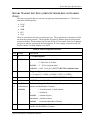
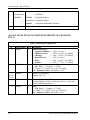
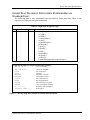
PACKAGE CONTENTS
As shipped from the II Morrow factory, the Apollo GX50/60/65 package includes most items
necessary for installation other than supplies normally available at the installation shop, such as
wire and cable ties, and required input and output equipment. The standard items included in the
package are listed in Table 1.
6
Apollo GX50/60/65 Installation Manual
Introduction
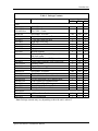
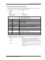
Table 1 Package Contents
Part #
Description
GX50
Units
430-6050-4xx
430-6050-6xx
430-6050-8xx
Install kits
162-0100
162-0103
162-1008
162-1060
202-0001
204-0037
204-2100
221-0400
224-0404
245-0022
310-5184-xx
310-5188-xx
998-0048
Manual kits
560-0961-xx
560-0959-xx
560-0928-xx
560-0963-xx
560-9000
561-0236-xx
561-0238-xx
Accessories
560-0949-xx
590-1104
GX50 GPS
GX60 GPS / Comm
GX65 GPS / Comm
Part number: 424-200715-pin dsub connector shell
37-pin dsub connector shell
Right angle coax plug
TNC coax connector
Cable tie
Edge grommet
Shoulder bushing
4-40 x 1/4 SS pan head Phillips machine screw
with lock washer
4-40 x 1/4 SS flat head Phillips machine screw
Crimp contact for dsub, 20 to 24 awg wire
Mounting frame
Connector mounting plate
3/32 hex driver
Part number: 564-0064GX GPS User’s Manual
GX50 / GX60 Installation Manual
GX GPS Approach User’s Manual Insert
GX60 Comm User’s Manual Insert
Binder, 5½ x 8½ x 1” 3 ring
GX60/65 Quick Reference Guide
GX50 Quick Reference Guide
Qty
GX60 GX65
1
1
-4xx
1
1
1
2
6”
2
4
6
37
1
1
1
-4xx
1
1
1
A-33 Installation Guide
A-33 GPS Antenna
1
-6xx
1
1
2
1
4
6”
4
4
1
-8xx
1
1
2
1
4
6”
4
4
8
52
1
1
1
-6xx
1
1
1
1
1
1
8
52
1
1
1
-8xx
1
1
1
1
1
1
1
1
1
1
1
1
Note: Package contents may vary depending on how the unit is ordered.
Apollo GX50/60/65 Installation Manual
7
Introduction
OTHER REQUIRED MATERIALS
The GX50/60/65 is intended for use with standard aviation accessories. External devices
required for various installations are listed in the System Configurations section on page 4.
Depending upon the installation, this will include items such as:
· annunciators
· a CDI or HSI
· a comm antenna
· a microphone(s)
· a speaker or headphones
SPECIAL TOOLS REQUIRED
Crimp Tool
A crimp tool meeting MIL specification M22520/1-01 and a positioner/locater are required to
ensure consistent, reliable crimp contact connections for the rear d-sub connectors. These tools
are available from:
For pin p/n 245-0022
Astro Tool Corp.
21615 SW TV Highway
Beaverton, OR 97006
Phone (503) 642-9853
Fax (503) 591-7766
Crimp tool:
Positioner:
Astro Tool part #615708
Astro Tool part #616356
For pin p/n 245-0027
ITT Cannon
1851 E. Deere Ave.
Santa Ana, CA 92705-6500
Insertion tool:
Regular duty Crimp tool:
Regular duty Locator tool:
Heavy duty Crimp tool:
Heavy duty Locator tool:
Phone (714) 261-5300
Fax
(714) 575-8324
ITT part # 274-7006-000 (Desc. CIET-20HD)
ITT part #995-0001-585 (Desc. M22520/1-01)
ITT part #995-0001-244 (Desc. TH25)
ITT part #995-0001-584 (Desc. M22520/2-01)
ITT part #995-0001-604 (Desc. M22520/2-08)
LICENSE REQUIREMENTS
An aircraft radio station license is required for operation of the GX60/65 comm transmitter
once installed in the aircraft. An application must be submitted on FCC Form 404, which may
be obtained from the FCC in Washington, DC, or any of its field offices. Procedures for
applications are in CFR 47, Part 87, Aviation Services, Subpart B, Applications and Licenses.
8
Apollo GX50/60/65 Installation Manual
Installation
SECTION 2 - INSTALLATION
This section describes the installation of the GX50 and GX60/65 including mounting, wiring,
and connections. A post installation check-out procedure is included at the end of this section.
PRE-INSTALLATION INFORMATION
Always follow good avionics installation practices per FAA Advisory Circulars (AC) 43.13-1A,
43.13-2A, AC 20-138, and AC 20-67B, or later FAA approved revisions of these documents.
Follow the installation procedure in this section as it is presented for a successful installation.
Read the entire section before beginning the procedure. Perform the post installation checkout before closing the work area in case problems occur.
INSTALLATION OVERVIEW
A successful installation should start with careful planning including determination of
mounting location for the GX50/60/65, antenna mounting, cable routing, and other required
modifications. Once the mounting location has been determined, prepare the mounting frame
for installation. It may be easier to complete the wiring harness and attach the connectors to
the mounting frame before installing the mounting frame.
INSTALLATION CONSIDERATIONS
MOUNTING CONSIDERATIONS
The GX50/60/65 is designed to mount in the avionics stack in the aircraft instrument panel
within easy view and reach of the pilot. The standard package includes a mounting frame for
ease of mounting, connections, and service of the unit. Allow an additional one inch clearance
to the rear of the mounting frame for connectors and cables.
For typical installations, the GX50/60/65 does not require external cooling. When mounting the
unit, ensure that a clearance of 1/8 to 1/4 inch exists between avionics units to allow for air
circulation.
MINIMUM SYSTEM CONFIGURATION
The minimum system configuration and external connection requirements are described in the
System Configurations section on page 4.
ALTITUDE INPUT
The GX50/60/65 includes an altitude input, which is used by the GPS RAIM calculations as
well as providing for altitude assist functions such as altitude preset and hold and 3D airspace
alerts. The altitude input is required for installations approved for non-precision approach
operation, optional for other installations.
The GX50/60/65 altitude input can be connected from either an altitude encoder/converter or
an air data converter. The minimum requirements for the altitude input are listed in the
specifications on page 36.
Apollo GX50/60/65 Installation Manual
9
Installation
HELICOPTER REQUIREMENTS
The GX60 and GX65 is qualified for helicopter installation with certain mount tube and
GX60/65 configurations (see Section 4 - Limitations).
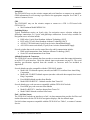
EQUIPMENT MOUNTING
Once the cable assemblies have been made, attach the 15 and 37 pin d-sub and coaxial cable
connectors to the rear connector mounting plate and the mounting frame as illustrated in Figure
4 and Figure 5. Route the wiring bundle as appropriate. The rear connector plate should be
attached to the mounting frame before installing the frame in the instrument panel. The rear
connector plate can be used to tie down the cable assemblies. Use the supplied edge guard to
protect the cable from sharp edges. Connect the shield grounds directly to the connector
mounting plate.
Once the cable assemblies, the connector mounting plate, and the mounting frame are
assembled, install the mounting frame assembly in the instrument panel as illustrated in
Figure 3. Be sure to use low profile head screws so the unit will slide in and out freely. Attach
the front of the mounting frame to the instrument panel. Use support brackets to attach the
rear of the frame to the aircraft.
10
Apollo GX50/60/65 Installation Manual
Installation
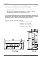
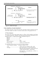
MOUNTING TUBE INSTALLATION
Care must be taken when installing the mounting tube to ensure you can properly insert and
secure the unit. There must be a minimum vertical spacing of 0.040 inches between units to
prevent interference with the cam locking mechanisms. Mounting tubes with clearance
dimples help maintain the proper clearance. The mounting tube must be installed with the
clearance dimples pointing up.
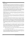
Figure 3 - Full Stack Mounting Tube Spacing
The mounting tube should be flush to the instrument panel and allow sufficient clearance for the
back of the bezel of the unit to mount flush to the mounting tube. Sufficient clearance must exist
in the instrument panel opening to allow ease of insertion and removal of the unit. If the back
of the unit bezel does not mount flush to the mounting tube, the connector may not
engage fully.
Secure the mounting tube to the instrument panel structure. Mounting screw heads must not
protrude into the mounting tube. Be sure to use the appropriate screws so the unit will slide in
and out freely. The screws attaching the mounting tube to the instrument panel structure must
not interfere with the insertion of the unit. Failure to prevent interference will result in
damage to the unit or prevent its insertion. Take care that the mounting tube is not distorted
when it is attached to the instrument panel and structural supports. Shims may be necessary to
properly install the mounting tube. If the mounting tube is distorted out of square, the unit may
either bind when being inserted or the cam lock may not engage.
Apollo GX50/60/65 Installation Manual
11
Installation
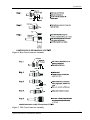
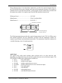
UNIT INSERTION
Position the cam lock as shown below. The front lobe of the cam should be vertical. The cam
lock mechanism should be fully unscrewed (turned counter-clockwise). Slide the unit into the
frame. Turn (clockwise) and carefully hand-tighten (4 in-lb max.) the cam lock mechanism
using only the 3/32" hex driver provided in the installation package. Using a larger tool than
the one provided makes it easy to exceed the allowable torque on the cam lock resulting in
damage to the unit. The unit will be pulled into the frame securing the unit and the connectors
will fully engage. Do NOT overtighten. The back of the bezel must only be flush to the
mounting tube. If the cam lock is hard to turn or the unit does not seat fully, the unit is
probably binding and the mounting tube should be checked.
UNIT REMOVAL
To remove the unit from the mounting frame, turn the screw counter-clockwise with the hex
driver to unscrew the cam lock mechanism. The unit will begin to pull away from the
mounting tube. Turn the screw until slight resistance is felt and then pull the unit from the
frame. Do not exert excessive turning force at the end of the cam lock travel or the unit
may be damaged. With the cam lock fully disengaged, pull the unit straight out holding onto
the sides of the bezel. It is not recommended that you pull the unit out by the rotary knobs. No
special extraction tools are required, if the mounting tube is properly installed.
12
Apollo GX50/60/65 Installation Manual
Installation
Figure 4 Mounting Frame Assembly
Figure 5 Cable Routing
Apollo GX50/60/65 Installation Manual
13
Installation
ELECTRICAL CONNECTIONS
Wiring necessary for installation of the GX50/60/65 includes the rear panel electrical
connections and the antenna cable placement. The 15 and 37 pin d-sub connectors and coax
connector(s) may be wired before or after being installed in the mounting frame. The
recommended connecting wire size for the connectors is 20 to 24 AWG. Wiring diagrams are
included on pages 18 through 24.
POWER
The GX60/65 requires two power connections, one for the GPS navigation side of the unit,
the other for the comm. Make the power connections to the unit using 20 AWG wire.
The GPS navigation power input is internally fused at 3 amps. A separate 2 amp (maximum)
circuit breaker or fuse should be installed for downline overload or short circuit protection.
The comm power input (GX60/65 only) is internally fused at 7 amps. A separate 5 amp (maximum)
circuit breaker or fuse should be installed for downline overload or short circuit protection.
Note: Circuits should be protected in accordance with guidelines in AC 43.13-1A,
chapter 11, section 2, paragraph 429.
Warning
When connecting power to the GX unit, reversing the polarity of the connection
will blow the internal fuse. The internal fuse is soldered onto the circuit board
and requires repair at the factory.
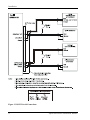
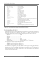
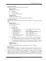
AVIONICS OUTPUTS
The GX50/60/65 includes avionics outputs for CDI/HSI indicators, autopilot, and
annunciators. These outputs are to be connected as appropriate for the particular installation.
The CDI/HSI outputs may be connected to a dedicated CDI or HSI or to a shared indicator
using an appropriate switching relay. The avionics outputs available are listed in the Avionics
Outputs specification on page 35. Connect the annunciator outputs to lamp indicators as
described in the specifications. The minimum connections required for different installations
are listed in the System Configurations on page 4.
If a switching relay is used to make connections to a shared CDI/HSI, it should be a minimum
of an eight pole relay box with an appropriate selector switch with annunciation. The ILS
enable signal (see Figure 8 and Figure 11) from a connected ILS receiver can be connected to
automatically switch the indicators back to the nav receiver when an ILS frequency is
selected.
SERIAL INTERFACE
The GX50/60/65 includes two RS-232 serial ports for making optional connections. The
serial ports can be used for connecting to such devices as the Apollo SL40 comm, a moving
map display, multi-function display, autopilot, VHF Nav/Com, Fuel Air/Data computer, or an
altitude encoder/converter. Serial output connections should be limited to no more than three
external units.
When making connections to the GX50/60, use a three-conductor shielded cable (for two-way
serial communication) or a two-conductor shielded cable (for one-way serial communication).
Make RxD, TxD, and signal ground connections to the 37-pin connector. Connect the shield(s)
to the rear of the mounting frame. The shield leads must be <1.25 inches. See Figure 5.
Complete serial interface specifications are included in Appendix E.
14
Apollo GX50/60/65 Installation Manual
Installation
SPEAKER AND HEADPHONE OUTPUTS (GX60/65 ONLY)
Connect the speaker and headphones to the output pins on the rear connector.
MICROPHONE INPUTS (GX60/65 ONLY)
Microphone input connections should be made using a twisted pair shielded cable. Attach the
signal ground to the mic ground pin on the rear connector and connect the shield to the rear
connector plate.
TRANSMIT KEY INPUT (GX60/65 ONLY)
The TxKey input on the rear connector must be pulled low to ground to enable the transmitter.
This input should be connected to a microphone or yoke mounted momentary push button switch.
INTERCOM SELECTOR SWITCH (GX60/65 ONLY)
The GX60/65 includes a voice activated intercom function that can be enabled by an external
control switch. This is an optional connection.
When making connection for the intercom selection, connect the intercom selection input to a
remote mounted normally open switch. A momentary toggle or alternate action switch can be
used. Connect the other terminal of the switch to ground. The intercom function is enabled
when the input is pulled low to ground. The monitor function is inhibited when the intercom
function is selected.
REMOTE FLIP/FLOP INPUT (GX60/65 ONLY)
The GX60/65 includes a remote flip/flop input. This is an optional input that can be
connected to a remote mounted (such as on the yoke) momentary push button switch which
pulls the input low to ground.
ANTENNA INSTALLATION AND CONNECTIONS
COMM ANTENNA (GX60/65 ONLY)
The GX60/65 requires a standard 50W vertically polarized antenna. Follow the antenna
manufacturer’s installation instructions for mounting the antenna.
The antenna should be mounted on a metal surface or a ground plane with a minimum area of
18 x 18 inches. The antenna should be mounted a minimum of two feet away from GPS
antennas.
The comm antenna should also be mounted as far apart as practical from the ELT antenna,
preferably one on top and the other on the bottom of the aircraft fuselage. Some ELTs have
exhibited re-radiation problems generating harmonics that may interfere with GPS signals.
This can happen when the comm (GX60/65 or any other comm) is transmitting on certain
frequencies such as 121.15 or 121.175 MHz, which may cause the ELT output circuit to
oscillate from the signal coming in on the ELT antenna coax.
The antenna coax cable should be made of RG-142B or a comparable quality 50W coax.
Assembly instructions for the rear coax connector are included in Figure 6.
Apollo GX50/60/65 Installation Manual
15
Installation
GPS ANTENNA
The mounting location and cable connections for the GPS antenna are very important. The
antenna should be mounted no closer than two feet from VHF comm transmitter antennas, six
inches from other antennas emitting less than 25 watts, and two feet from higher power
antennas. Special care should be taken to ensure that the GPS antenna is not mounted in close
proximity to antennas that may emit harmonic interference at the L1 frequency of
1575.42 MHz. Refer to the antenna installation manual for installation instructions.
The connectors are included in the installation kit, and are intended for use with RG-142B size
coax cable. If using a different diameter coax, alternative connectors may be required. Assembly
instructions for the connectors are included in Figure 6 and Figure 7. RG-142B cable can be used
as long as the length is less than 20 feet. For longer lengths, use a low loss 50W coax.
Suggestion: Temporarily locate the GPS antenna with coax connected to the GX50/60/65 and
check the GPS performance as described in the GPS Operation and Position test in the Post
Installation Checkout on page 27. Once a suitable location has been verified, then
permanently mount the antenna.
Note: If using a GPS antenna that was already on the aircraft, or if mounting the antenna
closer than two feet from a comm antenna, conduct the GPS Operation and Position test in
the Post Installation Checkout on page 27. If the GX50/60/65 passes the test, then moving the
antenna is not necessary.
Once the antenna mounting position has been prepared, route the coax cable from the antenna
to the GX50/60/65. Proper selection of coax cable and assembly of connectors is critical to
GPS signal performance. The cable loss from the antenna to the GX50/60/65 should be
limited to a maximum of 4 dB. Minimize the coax length for optimum performance and DO
NOT coil excess cable. Leave only enough for service loops. The coaxial connectors and
adapters, such as TNC to BNC, add additional loss to the cable and should be considered
when computing the maximum 4 dB loss. A typical loss of 0.2 dB can be used for each
connection. The typical cable loss for 20 feet of RG-142B coax with a connector on each end
is 4 dB.
During the post-installation checkout, susceptibility to harmonics of VHF comm transmitters
will be evaluated. If problems arise, then better isolation, or distance, may be required
between the GPS and comm antennas, or a notch filter may be installed in series with the
antenna coax of the VHF comm transceiver to reduce or eliminate the harmonic interference.
A notch filter for this use (part #162-1059) is available from II Morrow.
Note: GX60/65 performance has been verified in typical installations and has not shown
problems with the built-in comm interfering with the GPS when installed according to
the recommended installation guidelines.
If a VHF comm transmitter causes problems with the GPS on the selected frequencies as
listed in the post-installation checkout, the problem may be due to the ELT. This can be
verified by disconnecting the ELT antenna coax at the ELT unit. If the ELT is found to cause
the problem, then contact the ELT manufacturer or replace the ELT.
16
Apollo GX50/60/65 Installation Manual
Installation
Figure 6 Rear Coax Connector Assembly
Figure 7 TNC Coax Connector Assembly
Apollo GX50/60/65 Installation Manual
17
Installation
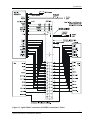
Figure 8 GX50/60/65 Power and Avionics Connections
18
Apollo GX50/60/65 Installation Manual
Installation
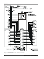
CDI+L
CDI+R
From+
To+
NAV Valid(+)
NAV Valid(-)
GS +Up
GS+Dn
GS Valid(+)
GS Valid(-)
NAV
INDICATOR
(CDI/HSI)
30
31
28
29
15
33
34
APOLLO
GX50/60
16
26
17
14
13
11
12
10
VDI (+)Up
VDI (-)Dn
VDI Valid(+)
VDI/Nav Valid(-)
ACTIVE
APPROACH
OBS/HOLD
MSG
GPS/SEQ(Obs/Hold)
PTK
CDI+L
CDI+R
From+
To+
Nav Valid(+)
NAV
Receiver
CDI+L
CDI+R
From+
To+
Nav Valid (+)
Nav Valid(-)
GS+Up
GS+Dn
GS Valid (+)
GS Valid(-)
NAV enable
GPS enable
Lamp Test
Dimmer High
Dimmer Low
Power(Vcc)
Ground
26
27
14
15
20
21
32
33
38
39
36
37
ANNUNCIATION
CONTROL
UNIT
(ACU)
42
25
8
12
9
10
13
11
30
31
18
19
24
28
29
16
17
22
23
34
35
40
41
4
5
6
43
44
78
1
Figure 9 - Apollo ACU to Apollo GX50/60 Wiring Diagram
Apollo GX50/60/65 Installation Manual
19
Installation
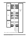
26
CDI+L
CDI+R
From+
To+
NAV Valid(+)
NAV Valid(-)
GS +Up
GS+Dn
GS Valid(+)
GS Valid(-)
NAV
INDICATOR
(CDI/HSI)
27
14
15
20
21
32
33
38
39
ANNUNCIATION
CONTROL
UNIT
(ACU)
28
29
30
31
APOLLO
GX65
16
17
14
13
11
12
10
NAV
Receiver
42
VDI Valid(+)
VDI/Nav Valid(-)
VDI (+)Up
VDI (-)Dn
25
36
37
10
MSG
PTK
CDI+L
CDI+R
From+
To+
Nav Valid(+)
11
30
31
18
19
24
28
CDI+L
CDI+R
From+
To+
Nav Valid (+)
Nav Valid(-)
GS+Up
GS+Dn
GS Valid (+)
GS Valid(-)
29
16
17
22
23
34
35
40
41
NAV enable
GPS enable
Lamp Test
Dimmer High
Dimmer Low
Power(Vcc)
Ground
4
5
6
43
44
78
1
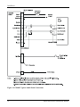
Figure 10 - Apollo ACU to Apollo GX65 Wiring Diagram
20
Apollo GX50/60/65 Installation Manual
Installation
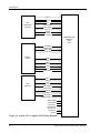
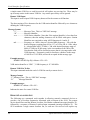
Figure 11 Apollo 50/60 Connections with MD41 Annunciator / Relay
Apollo GX50/60/65 Installation Manual
21
Installation
Figure 12 RS-232 Serial Connections
22
Apollo GX50/60/65 Installation Manual
Installation
Figure 13 GX60/65 Comm Wiring Diagram
Apollo GX50/60/65 Installation Manual
23
Installation
Figure 14 GX60/65 Typical Audio Panel Connections
24
Apollo GX50/60/65 Installation Manual
Installation
POST INSTALLATION CHECKOUT
Once the unit is installed, complete the checkout procedure to verify proper operation. Refer
to the User’s Guide for operating instructions.
The steps that are not applicable to a particular installation may be skipped. A checkout log
sheet is included on page 31 to fill out during the checkout procedure. Make a photocopy of
the log sheet for ease of use if desired.
The checkout procedure is broken into several groups. The GPS Navigation Checkout, VHF
Comm Checkout (GX60/65), and the Final System Check should be completed with the
aircraft moved clear of hangers and other structures.
Mounting / Wiring Check
Verify that all cables are properly secured and shields are connected to the rear of the
mounting frame. Check the movement of the aircraft controls to verify that there is no
interference.
TEST MODE CHECKOUT AND SETUP
The GX50/60/65 has a built-in test mode to simplify the checkout. To operate the
GX50/60/65 in the test mode, hold down the leftmost and rightmost “smart keys” while
switching on the power. To return to normal operation, switch the power off, then back on.
Avionics Outputs
Check the avionics output connections by using the test mode as follows. Rotate the LARGE
knob to select each test.
1. Using the “CDI TRIANGLE” page, rotate the SMALL knob to check left, mid, and right.
2. Using the “VDI TRIANGLE” page, rotate the SMALL knob to check down, mid, and up.
3. Using the “TO/FROM FLAG” page, rotate the SMALL knob to check the Off, To, and From
outputs.
4. Using the “LAMP OUTPUTS” page, rotate the SMALL knob to check all the connected
annunciators.
5. Using the “VALID FLAG PAGES” page, rotate the SMALL knob to check all the connected
valid flag outputs.
Installation Configuration
The GX50/60/65 must be configured to match the operation supported by the installation.
This includes IFR, VFR, approach, and Search and Rescue operation selections.
1. In test mode, rotate the LARGE knob to the “INSTALL OPTIONS” page.
2. Press SEL. Rotate the SMALL knob to select IFR operation (YES or NO). Rotate the LARGE
knob for APPR* selection. Rotate the SMALL knob to select approach operation (YES or
NO). Rotate the LARGE knob for SAR (Search and Rescue) selection. Rotate the SMALL
knob to select SAR operation (YES or NO). Press ENT when complete. (Note: APPR can
only be set to YES when IFR is set to YES).
* (GX50/60 only)
Note: Make sure that all installation requirements are complete for the selected operation.
Refer to the System Configurations section on page 4 for installation requirements.
Apollo GX50/60/65 Installation Manual
25
Installation
Serial Interface Configuration
The GX50/60/65 RS-232 serial ports can be configured for several input and output formats.
To select the serial port configurations:
1. In test mode, rotate the LARGE knob to the serial port configuration “CH RX TX” page.
2. Press SEL (the selection fields will start flashing), rotate the LARGE knob to select the port,
rotate the SMALL knob to select the desired configurations, then press ENT when complete.
The available serial port configurations are included in Appendix E. Serial output connections
should be limited to no more than three external units. An example of the typical settings for
the RS-232 selections for most installations would be:
CH
1:
2:
Rx
NAV
AltEnc
Tx
MapCom
GPSS
Comm Radio Setup
The Test Mode settings may also be used to preset the Microphone (Mic) Gain and the
Receiver Squelch levels.
Mic Gain
Set the microphone gain for microphones 1 and 2 for values from 0 to 255.
1. In the Test Mode, rotate the LARGE knob to select "Mic Gain."
2. Press SEL to activate selection. The Mic 1 value will flash.
3. Turn the SMALL knob to change the value.
4. Turn the LARGE knob to the Mic 2 value. Turn the SMALL knob to change the value.
5. Press ENTER to accept and save the settings.
Receiver Squelch
Preset the receiver squelch level for values from 25-100.
1. In the Test Mode, rotate the LARGE knob to select "Receiver Squelch."
2. Press SEL to activate selection. The value will flash.
3. Turn the SMALL knob to select a value.
4. Press ENTER to accept and save the settings.
Other Test Mode Pages
The GX50/60/65 test mode includes several other pages that are not necessary for the
checkout. They are as follows:
“TO TEST DISPLAY” ...................... Can be used to check the GX50/60/65 front panel displays
by pressing ENTER.
“TEST CONTROLS” ........................ Can be used to check the GX50/60/65 front panel
controls. Press each button and rotate the SMALL knob to
check the controls.
“OPERATION STATUS:”................. Factory use only. Should be set to “STANDARD.”
26
Apollo GX50/60/65 Installation Manual
Installation
“SYSTEM INITIALIZATION” ............Factory use only. Used to reset all internal memory
including user waypoints, flight plans, and configuration
data.
Caution: Using the system initialization function
will cause all user data to be lost!
“SERIAL PORT TEST” .....................Factory use only. Used to check the RS-232 serial ports.
"Extended MovMap
Data Format" ................................Enable/Disable extended moving map data. This should
be enabled when interfaced with an Apollo MX20 or
Sandel HSI. Call Customer Service if you have questions.
“A/D CHANNEL 1”.........................Factory use only. Used to check internal circuits and
display voltages.
“EEPROM BYTE 0000:” ...............Factory use only. Used to display eeprom setup memory.
GPS NAVIGATION CHECKOUT
Switch on the GX50/60/65 in the normal mode to complete this part of the checkout. The
GX50/60/65 will go through a sequence of self tests.
The GX50/60/65 requires a “seed” position, time, and date for the GPS sensor to know which
satellites to look for. Once this is entered, it will be saved and updated automatically. If the
GX50/60/65 is moved a great distance without being turned on, the seed position may have to
be re-entered.
Entering the seed position:
1. During the display startup sequence, press SEL when the position page is displayed.
2. Rotate the LARGE knob to move the cursor to different fields, rotate the SMALL knob to
input the correct lat/lon, and then press ENT to save the changes.
The seed position can also be input with reference to a waypoint. Refer to the user’s manual
for instructions.
Entering the time and date:
The time and data can be entered after the power up sequence from the nav page display.
1. Press the SYS button, rotate the LARGE knob to display the “SYSTEM INFO” page, and
press ENTER.
2. Press SEL, rotate the LARGE knob to move the cursor to different fields, rotate the SMALL
knob to input the correct time, and then press ENT to save the changes.
GPS Operation and Position
This checkout is to be completed with the aircraft moved away from hangars and other
structures that may obstruct the view of the satellites.
1.
2.
Turn on the GX50/60/65 and allow the unit to acquire a position. All other avionics
should be turned off for this part of the test.
Check the position using the lat/lon navigation page. Press the NAV button and rotate the
LARGE knob to the lat/lon page. The lat/lon should agree with a known reference position.
Apollo GX50/60/65 Installation Manual
27
Installation
3.
4.
5.
Check the signal reception using the GPS sensor displays in the System mode. Press the
SYS button, rotate the LARGE knob to the “GPS SENSOR:” page, and press ENT. Then
rotate the SMALL knob to display the GPS info. Typical signal levels are 50 or better.
Turn on other avionics one at a time and check the GPS signal reception to make sure it
is not affected.
Check for VHF comm transmitter interference. This must be completed on all IFR
installations.
a) Verify that 5 to 8 satellites are in DATA and the NAV flag is out of view.
b) Tune the comm to 121.150 MHz and transmit for 20 seconds.
c) Verify that the position is not lost.
d) Repeat for additional frequencies as follows.
121.125 MHz
131.225 MHz
121.175 MHz
131.250 MHz
121.200 MHz
131.275 MHz
121.225 MHz
131.300 MHz
121.250 MHz
131.325 MHz
131.200 MHz
131.350 MHz
e) Repeat for each comm transmitter.
f) If the GX50/60/65 is susceptible to VHF comm transmitter interference, then better
isolation, or distance, may be required between the GPS and VHF antennas. With
some comm transmitters, a notch filter may be required in series with the VHF
comm antenna coax at the rear of the comm unit.
Note: Older VHF comm transmitters may emit higher levels of harmonic interference
causing greater problems and may be more difficult to deal with.
VHF COMM CHECKOUT (GX60/65)
Receiver / Transmitter Operation
Tune the unit to a local frequency and verify the receiver output produces a clear and
understandable audio output. Verify the transmitter functions properly by contacting another
station and getting a report of reliable communications. Check the remote flip/flop.
Antenna Check
The antenna VSWR can be checked using an inline wattmeter in the antenna coax using
frequencies near both ends of the band. The VSWR should be < 2:1, and is not to exceed 3:1.
A VSWR of 2:1 will cause a drop in output power of approximately 12%, and 3:1 causes
approximately a 26% drop.
Sidetone Level Adjustment
The sidetone volume was preset at the factory to a typical audio level. The level can be
adjusted using one of the built-in system functions. To adjust the sidetone level:
1. Press SYS, rotate the LARGE knob to the “COM INFO” page, and press ENT.
2. Rotate the LARGE knob to the “SIDETONE LEVEL” page.
3. Press SEL, rotate the SMALL knob to adjust the sidetone level, then press ENT when
complete. The sidetone level is displayed in a range of 000 to 255, with 255 the highest
level. The sidetone level can be adjusted during transmit.
28
Apollo GX50/60/65 Installation Manual
Installation
Comm Flight Test Check
A flight test is recommended as a final installation verification. The performance may be
verified by contacting a ground station at a range of at least 50nm while maintaining an
appropriate altitude and over all normal flight attitudes. Performance should be checked using
low, high, and mid band frequencies.
FINAL SYSTEM CHECK
The GX50/60/65 GPS navigation functions should be complete at this time. The final check
includes checking database, entering a direct to waypoint, and checking the navigation
functions. Start with the unit turned on and operating in the normal mode. Refer to the user’s
manual for operating instructions.
1. Verify a valid position is displayed.
2. Check the database to ensure it is for the right coverage area and check the expiration
date. To check the database:
a) Press SYS, rotate the LARGE knob to the “SYSTEM INFO” page, and press ENT.
b) Rotate the LARGE knob to the Apollo GX “SOFTWARE VERSION” page
c) Rotate the SMALL knob to display the database information. The database name,
expiration date, and version will be displayed.
3. Enter a direct to waypoint. Press the DIRECT-TO button, use the LARGE and SMALL
knobs to select a nearby waypoint, then press ENT. Or use the nearest search function to
select a waypoint.
4. Verify the bearing and distance to the selected waypoint.
If the database is expired, or if a different coverage area is needed, contact the II Morrow
factory for an update.
INTERFACE CHECKS
The interfaces to other equipment, such as the SL40 or a moving map display, should be
checked. Make sure the other equipment is connected and switched on. The Apollo GX must
have a seed position and be navigating to a waypoint to check the interfaces.
Apollo SL30
When your Apollo GX is connected to and configured to communicate with an Apollo SL30
Nav/Comm, your Apollo GX will exchange information with the SL30. If the following steps
do not perform correctly, check the electrical connections and configuration setup.
1. In the Apollo GX, view Tuned Station page in Nav mode. The tuned station identifier and
frequency sent by the Apollo SL30 should be displayed.
2. In the Apollo SL30, Distance, Speed, and Time information for the selected station should
be displayed. The Distance, Speed, and Time information for the selected station shown in
the SL30 ensures that the GX and SL30 are communicating.
If your Apollo SL30 is only configured to receive, use the following steps for checkout.
1. In the SL30, press NAV.
2. Then, press SEL.
3. Note the you should see the three to four letter designator for either the Localizer for the
destination or the closest VOR to your current position.
Apollo GX50/60/65 Installation Manual
29
Installation
Apollo SL40
The Remote function will allow the SL40 to access the airport frequency database in an
Apollo GPS receiver. If the following steps do not perform correctly, check the electrical
connections and configuration setup.
1. In the SL40, press RCL to view the Remote (REM) frequencies.
2. Then, turn the SMALL, inner knob to display the available frequencies. The waypoint type
and frequency received from the GX are displayed.
Apollo MX20
The Apollo MX20 must be installed and setup according to its installation manual. If the
following steps do not perform correctly, check the electrical connections and configuration
setup.
1. Check the System Info page on the MX20 to verify that the data is available to each port
and that it is being processed properly.
2. The GX Flight plan will be displayed on the MX20 on the FPL page.
Altitude Encoder and Fuel Air/Data Computer
In the System Mode check the Misc Sensors function. If the following steps do not show the
correct information, check the electrical connections and configuration setup.
1. Press SYS. Turn the LARGE knob to Misc Sensors and press ENTER.
2. The Encoding Altimeter value will be displayed.
3. Turn the LARGE knob to view Air Data Info.
4. Turn the LARGE knob to view Fuel Info.
Autopilot
The Apollo GX provides GPSS roll steering information to an appropriate autopilot. When
connected properly, the autopilot will show a GPSS valid indication when the aircraft reaches
a speed over 5 kts and is navigating to a waypoint.
1. Apply power to the equipment and wait for the GX to acquire a position.
2. In the GX, set a course to a destination waypoint. For instance; press NRST, select airport
with the SMALL knob, and press DIRECT-TO.
3. Taxi the aircraft faster than 5 kts.
4. Verify that GPSS is valid via the autopilot annunciation.
Annunciator Control Unit (ACU)
Once the unit is installed, complete the checkout procedure to verify proper operation. Refer
to the User’s Guide for operating instructions.
30
Apollo GX50/60/65 Installation Manual
Installation
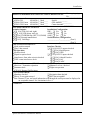
APOLLO GX50/60/65 POST-INSTALLATION CHECKOUT LOG
Date: ___/___/___
By: _____________
CONFIGURATION INFORMATION:
o GX50 GPS
430-6050-4__ Mod ____
Serial # ___________
o GX60 GPS/Comm 430-6050-6__ Mod ____
GPS Antenna ___________
o GX65 GPS/Comm 430-6050-8__ Mod ____
Comm Antenna: ___________
TEST MODE CHECKOUT AND SETUP:
Avionics Outputs:
Installation Configuration:
o [o N/A] CDI (left, mid, right)
IFR?: o Yes o No
o [o N/A] VDI (down, mid, up)
APPR? o Yes o No
o[o N/A] TO/FROM flag (OFF, TO, FROM) SAR?: o Yes o No
o[o N/A] External annunciators
Serial Interface Configuration:
o [o N/A] Valid flags
_____________/____________ (Port 1)
_____________/____________ (Port 2)
GPS NAVIGATION CHECKOUT:
o Seed position entered
Interface Checks:
o Time, date entered
o [o N/A] RS-232 outputs checked
o [o N/A] Map/Mapcom
GPS Operation:
o Position check
o [o N/A] GPSS
o Signal reception check
o [o N/A] RS-232 inputs checked
o Interference from other avionics checked
o [o N/A] Altitude Encoder
o VHF comm interference check
o [o N/A] NAV
o [o N/A] F/ADC
VHF COMM CHECKOUT: (GX60/65 ONLY)
o Receiver / Transmitter operation
o Sidetone level set / checked
o Antenna check
o Flight test operation
o [o N/A] Remote flip/flop input
FINAL SYSTEM CHECK:
o Database checked
o Navigation data checked
o Direct To waypoint entered
o DST data acceptable*
* Note: Distance, Time, and speed information sent through the serial port must be displayed in
an acceptable manner. See Limitations in Sec. 4.
COMMENTS:
Apollo GX50/60/65 Installation Manual
31
Installation
NOTES
32
Apollo GX50/60/65 Installation Manual
Specifications
SECTION 3 - SPECIFICATIONS
This section includes detailed electrical, physical, environmental, and performance
specifications for the Apollo GX50 and GX60/65.
ELECTRICAL
Input voltage............................................. 10VDC to 40VDC, reverse polarity protected
Input current (GPS navigation input) ....... 500 mA typical, 750 mA max. at 13.75 VDC
250 mA typical, 375 mA max. at 27.5 VDC
Input current (comm input) ...................... 270 mA typical, 2A max. at 13.75 VDC, receive
130 mA typical, 900 mA max. at 27.5 VDC, receive
2.1 A typical, 3.2 A max. at 13.75 VDC, transmit
1.0 A typical, 1.4 A max. at 27.5 VDC, transmit
Note: Receive max. at full receive audio, transmit
max. at 90% modulation at 1000 Hz
Input power (GPS navigation input) ........ 7 watts typical
Input power (comm input)........................ 3.7 watts typical, receive
28 watts typical, transmit
Internal fuses ............................................ Nav input: 3 amp fast blow, surface mount on-board
Comm input : 7 amp fast blow, soldered in-board
Fuses must be replaced with the same or equivalent
type (contact the factory).
Memory backup........................................ Internal lithium battery with a service life of
approximately 4 to 6 years. See Appendix B for
battery replacement instructions.
Note: The GX50/60/65 will provide a message on the display when the Lithium battery is
running low and needs replacement.
PHYSICAL
Height ....................................................... 2.00 inches (5.08 cm)
Width ........................................................ 6.25 inches (15.88 cm)
Depth ........................................................ 11.45 inches (29.1 cm) behind panel, including
mounting frame and connectors
Weight (with mounting frame)................. GX50: 2.6 lb. (1.179 kg)
GX60/65: 3.1 lb. (1.409 kg)
Apollo GX50/60/65 Installation Manual
33
Specifications
Figure 15 Unit Dimensions
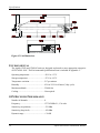
ENVIRONMENTAL
The Apollo GX50 and GX60/65 units are designed and tested to meet appropriate categories
of RTCA/DO-160C. The Environmental Qualification Form is included in Appendix C.
Operating temperature ..............................-20°C to +55°C
Storage temperature ..................................-55°C to +85°C
Temperature variation...............................2°C per minute
Humidity ...................................................95% at 50°C for 6 hours (2 day cycle)
Maximum altitude.....................................55,000 feet
Cooling......................................................Not required
GPS RECEIVER PERFORMANCE
Number of channels ..................................8
Frequency..................................................1575.42 MHz L1, C/A code
Sensitivity (acquisition) ............................-135 dBm
Sensitivity (drop lock) ..............................-142 dBm
Dynamic range ..........................................> 20 dB
34
Apollo GX50/60/65 Installation Manual
Specifications
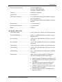
Lat/Lon position accuracy........................ 15 meters RMS typical
25 meters, SEP, without SA
100 meters 2DRMS with SA
Velocity .................................................... 1000 knots maximum
Acceleration ............................................. 4G maximum
TTFF (time to first fix)............................. 25 seconds typical with current almanac, position,
time, and ephemeris
55 seconds typical with current almanac, position,
and time
Reacquisition............................................ 2.5 seconds typical
Position update interval............................ 1 second typical
Datum ....................................................... WGS-84
AVIONICS OUTPUTS
CDI L/R deviation.................................... ±150 mv full scale, will drive up to 200 ohm load
TO/OFF/FROM flag ................................ ±250 mv, TO/FROM indication, will drive up to
200 ohm load
Nav valid flag ........................................... +300 mv for valid indication, will drive up to 100
ohm load
Nav superflag ........................................... Vin - 2 volts minimum for valid, source capability
of 400 mA
VDI up/down............................................ ±150 mv full scale, will drive up to 200 ohm load
VDI valid flag........................................... +300 mv for valid indication, will drive up to 100
ohm load
VDI superflag........................................... Vin - 2 volts minimum for valid, source capability
of 400 mA
Annunciators ............................................ Open collector outputs capable of sinking up to
400 mA for turning ON annunciator lamps
·
·
·
·
·
Apollo GX50/60/65 Installation Manual
MSG (message) ON indicates message(s) active
PTK (parallel track) ON indicates parallel track
is enabled
OBS/HLD (waypoint sequencing hold) ON
indicates waypoint sequencing is on hold
APPRCH (approach enabled) ON indicates the
approach has been enabled
ACTIVE (approach active) ON indicates the
approach is active
35
Specifications
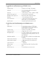
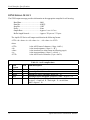
ALTITUDE INPUT REQUIREMENTS
The altitude data can be input to the GX50/60/65 from either an altitude encoder or serializer,
or from an air data computer.
The minimum requirements of the optional altitude data input are as follows:
Input method .............................................RS-232
Type ..........................................................pressure altitude
Resolution .................................................100 feet minimum
Accuracy ...................................................must meet accuracy requirements of TSO-C88a
Note: Installation of altitude input equipment, such as encoders, must be done according to
their installation instructions.
Note: Specifications for the RS-232 altitude input are included on pages 67 to 68.
ANNUNCIATOR REQUIREMENTS
The GX50/60 installed for IFR non-precision approach operation requires the following
annunciators (upper annunciator pictured below). Each annunciator should include a lamp of
the proper voltage for the installation. The lower annunciator is suitable for the GX65.
Legend
Color
MSG
amber
PTK
blue or white
OBS/HLD
blue or white- with included momentary switch
APPRCH
blue or white
ACTIVE
green
Installations that do not include non-precision approach operation may be made with the
MSG and PTK annunciators only.
The annunciators should be connected to a suitable dimming circuit for night time operation.
amber
blue
Momentary Push Button
MSG
WPT SEQ APPRCH
PTK
OBS/HLD
blue
ACTIVE
blue
green
Figure 16 - Example Annunciators
36
Apollo GX50/60/65 Installation Manual
Specifications
COMM RECEIVER PERFORMANCE (GX60/65 ONLY)
Class ......................................................... D
Frequency range ....................................... 118.000 to 136.975 MHz, 760 channels
Sensitivity................................................. 1mV (2mV hard) for 6dB S+N/N with 30%
modulation at 1000Hz
Selectivity................................................. < 6dB variation at ± 7 kHz, > 60dB at ± 22 kHz
Speaker audio output level ....................... 12 watts into 4W, 8 watts into 8W
Headphone audio output level.................. 280 mW into 100W, 120mW into 500W
Distortion.................................................. < 5% at rated output at 1000 Hz
AGC characteristics.................................. < 3dB variation in audio output from 5mV to
100mV input, 15% to 90% modulation
Squelch control......................................... Automatic squelch with manual override
COMM TRANSMITTER PERFORMANCE (GX60/65 ONLY)
Class ......................................................... 4
Output power............................................ 8 watts minimum carrier at >12VDC input,
6 watts minimum at 10VDC input (transmit is
locked out below 9 volts input)
Frequency range ....................................... 118.000 to 136.975 MHz, 760 channels
Frequency tolerance ................................. ±15ppm from -20°C to +70°C
Microphone input ..................................... Two inputs, standard carbon or dynamic mic with
integrated preamp providing minimum 70mV rms
into 1000W load
Modulation capability .............................. 85% with 100mV to 1000mV rms microphone input
at 1000 Hz
Audio frequency distortion....................... < 10% at 85% modulation at 350 to 2500 Hz
Audio frequency response........................ < 4 dB variation with 350 to 2500 Hz, 85%
modulation
Carrier noise level .................................... > 35 dB down
Sidetone output......................................... up to 280 mW into 100W, 120 mW into 500W
Duty cycle ................................................ 100%
Stuck mic time-out ................................... 35 second time-out, reverts to receive
Apollo GX50/60/65 Installation Manual
37
Specifications
INTERCOM PERFORMANCE (GX60/65 ONLY)
Microphone input......................................Two inputs, standard carbon or dynamic mic with
integrated preamp providing minimum 70 mV rms
into 1000W load
Headphone audio output level ..................280 mW into 100W, 120mW into 500W
AGC characteristics ..................................output varies < 3dB with input of 100mV rms to
1000 mV rms
CONTROL INPUTS
Simulator select.........................................Must be connected to ground for normal operation,
leave open for built-in simulator operation
Hold select ................................................Waypoint sequencing hold input, connect to
momentary button to ground for hold input
operation, should be combined with the OBS/HLD
annunciator (optional on GX65)
Transmit key (GX60/65)...........................Input pulled low to ground to enable the transmitter
Intercom select (GX60/65) .......................Input pulled low to ground to enable the intercom
function
Flip/Flop (GX60/65) .................................Remote comm flip/flop input, connect to a
momentary button to ground for remote flip/flop
operation.
ANTENNA REQUIREMENTS
GPS ANTENNA
The GX50 and GX60/65 are designed to operate properly with the A-33 or A-34 GPS
antennas. The GX50/60/65 supplies 5 volts for the antenna.
COMM ANTENNA
The Apollo GX60/65 requires a VHF comm antenna meeting the following specifications.
Standard 50W vertically polarized antenna with a VSWR < 2.5:1.
SERIAL INTERFACE
RS-232 ......................................................Defined in Appendix E - Serial Interface
Specifications
38
Apollo GX50/60/65 Installation Manual
Specifications
REAR CONNECTOR PINOUT
The GX60/65 includes two rear panel connectors, a 15 pin for the comm interface
connections and a 37 pin for the GPS navigation connections. The GX50 uses only the 37 pin
connector. The pinout for the connectors is listed in the following tables.
Table 2 Comm Interface Connector Pinout
Pin #
I/O
Connection
Function
1
2
3
4
5
6
7
8
9
10
11
12
I
I
O
I
-O
I
I
I
I
O
I
Power +
Reserved
Reserved
TxKey
NC
Speaker
Mic ground
Mic 1
Power ground
Reserved
Reserved
Intercom select
13
14
15
O
O
I
Audio ground
Headphone
Mic 2
main DC power input
do not connect
do not connect
transmit enable key, pulled low to transmit
do not connect
speaker terminal output
microphone input ground connection
microphone input #1
main power ground input
do not connect
do not connect
intercom function select, pulled low to turn on the intercom
function
speaker and headphone ground connection
headphone terminal output
microphone input #2
Apollo GX50/60/65 Installation Manual
39
Specifications
Table 3 Navigation Interface Connector Pinout
40
Pin #
I/O
1
2
3
4
5
6
7
8
9
10
11
12
13
14
15
16
17
18
19
20
21
22
23
24
25
26
27
28
29
30
31
32
33
34
35
36
37
I
I
O
I
O
I
I
I
O
O
O
O
O
O
O
O
O
--O
I
O
-O
O
I
O
O
O
O
O
O
O
O
O
O
O
Connection
Function
Power +
Power ground
Serial ground
RxD1
TxD1
Ext in 2
Simulator select
Flip/Flop
VDI Superflag
Nav + valid
+ FROM
+ TO
CDI + Right
CDI + Left
ACTIVE
MSG
PTK
reserved
reserved
Serial ground
RxD2
TxD2
reserved
reserved
Ground
Hold select
Nav superflag
VDI + valid
Ground
VDI + Up
VDI + Down
Ground
APPRCH
Hold
reserved
Power control
Ground
main DC power input
main power ground input
RS-232 signal ground
RS-232 channel 1 serial data input
RS-232 channel 1 serial data output
reserved
simulator mode, connect to ground for normal operation
Remote comm frequency flip/flop input - GX60/65 only
VDI high level superflag output
Nav low level valid flag output
+ From flag output
+ To flag output
CDI + Right output
CDI + Left output
Approach Active annunciator output (GX50/60 only)
Message annunciator output
Parallel track annunciator output
do not connect
do not connect
RS-232 signal ground
RS-232 channel 2 serial data input
RS-232 channel 2 serial data output
do not connect
do not connect
signal ground connection
Hold input (GX65 optional)
Nav high level superflag output
VDI low level flag output
valid flag ground connection
VDI + Up output
VDI + Down output
signal ground connection
Approach annunciator output (GX50/60 only)
Hold annunciator output (GX65 optional)
do not connect
Power control output
reserved
Apollo GX50/60/65 Installation Manual
Limitations
SECTION 4 - LIMITATIONS
INSTALLATION
For minimum equipment and connections required for VFR or IFR installations, refer to the
System Configurations on page 4.
Installations of the GX50/60/65 GPS navigation functions are to be made in accordance with
AC 20-138, or other appropriate FAA approved guidelines.
Installations of the GX60/65 comm functions are to be made in accordance with AC 20-67B
or other appropriate FAA approved guidelines.
When the GX50/60/65 is installed for VFR, a placard stating “GPS Limited to VFR Use
Only” or an FAA approved equivalent statement must be placed next to the primary indicator.
When Nav tuning is provided to the GX, the GX will output Distance, Speed, and Time
(DST) information on the MapCom output. It is the installer’s responsibility to ensure that
this information is displayed in an acceptable fashion. For instance, in an installation where
two Apollo SL30’s are integrated in the system, it is not appropriate to display DST
information on the SL30 that is not providing the tuning information. Apollo SL30 SW
version 1.2, or later, provides the means for disabling the display of DST information.
The GX60 and GX65 are qualified for helicopter installation only when the correct mounting
hardware and GX configurations are used. Mount Tube p/n 310-5184-01 and Connector
Mounting Plate p/n 310-5188-01 (or later FAA-approved revisions) are required for
helicopter installations and recommended for all installations. GX60 p/n 430-6050-605 (or
later FAA-approved revision) or GX60 units upgraded with Mod AD should be used in
helicopter installations. GX65 p/n 430-6050-805 (or later FAA-approved revision) or GX65
units upgraded with Mod AB should be used in helicopter installations.
OPERATIONAL
An approved Aircraft Flight Manual Supplement is required for IFR installations.
Note: A sample AFM supplement is available from II Morrow (UPS Aviation Technologies)
listing operational limitations.
An aircraft radio station license is required with the GX60/65 for transmitting.
For approach use with software version 3.3 or greater, a data card with a cycle date of
7/12/01, or later, must be used.
Apollo GX50/60/65 Installation Manual
41
Limitations
NOTES
42
Apollo GX50/60/65 Installation Manual
Troubleshooting
APPENDIX A - TROUBLESHOOTING
This appendix provides information to assist troubleshooting if problems occur after
completing the installation. Use Table 4 to assist in troubleshooting.
Table 4 Troubleshooting Guide
Problem
Cause
The GX50/60/65 does not
power on.
The GX50/60/65 does not
compute a position.
The unit is not getting power.
Solution
Check power connections, breakers,
and main avionics switch.
Not receiving signals, or incorrect
Make sure a correct position and
seed position, time, and date.
time/date have been entered. Check
the GPS antenna connections. Make
sure the aircraft is clear of hangers,
buildings, trees, etc.
The GPS signal levels are very Improper antenna installation or coax Check GPS antenna installation,
low.
routing.
connections, and cable routing. The
GPS antenna must be mounted on the
top of the aircraft.
Antenna shaded from satellites.
Make sure the aircraft is clear of
hangers, buildings, trees, etc.
RF interference at 1575.42 MHz from Move GPS antenna further from the
VHF comm.
comm antenna. Add a 1575.42 MHz
notch filter in comm coax. Fix or
replace the comm. Disconnect the
ELT antenna coax to check..
GPS signal levels drop when
Noise interference from other
Turn all avionics off, then turn on
avionics are turned on.
avionics.
each piece one at a time to isolate the
source of the interference. Route
cable and antenna away from sources
of interference.
The GX60/65 does not transmit. The TxKey input is not being pulled Check the TxKey (mic key) input,
low.
pulled low for transmit.
A weather channel is selected.
Select a different frequency, the unit
will not transmit on a weather
channel.
No power to the comm.
Make sure power input is connected
to the comm 15-pin connector.
The input voltage is too low.
Increase input supply voltage to > 9
volts DC.
The sidetone level is too low or Wrong type of headsets, or level
See the Sidetone Level Adjustment
too high.
needs adjustment.
on page 28.
The intercom doesn’t function. Control input not connected.
The intercom select input must be
pulled to ground to turn on the
intercom function.
Active frequency signal present.
Change the active frequency. The
active frequency has priority.
No voice activation, or have to talk
Change the intercom squelch
too loud.
threshold using the setup function
described in the user’s manual.
Apollo GX50/60/65 Installation Manual
43
Troubleshooting
Table 4 Troubleshooting Guide
Problem
Cause
Solution
Display flashes from power
interrupts
Caused by momentary power
interruptions in the electrical system,
typically due to changing power
sources.
This is normal operation of the
GX50/60/65, operation recovers in
approximately 1 second. If it
becomes a problem, check the
electrical system.
CONTACTING THE FACTORY FOR ASSISTANCE
If the Apollo GX50/60/65 unit fails to operate despite troubleshooting efforts, contact the
II Morrow factory for assistance.
II Morrow Inc.
2345 Turner Rd. SE
Salem, Oregon 97302
USA
Phone (503)581-8101 or 1-800-525-6726
Be prepared with the following information about the installation:
· Installation configuration (accessories, antenna, ...)
· Model number, part number with mod levels, and serial number
· Software versions
· Description of problem
· Efforts made to isolate the problem
· other installed avionics
44
Apollo GX50/60/65 Installation Manual
Periodic Maintenance
APPENDIX B - PERIODIC MAINTENANCE
The GX50/60/65 unit is designed to not require any regular general maintenance except as
included in this section.
LITHIUM BATTERY REPLACEMENT
The internal keep alive battery will require replacement after 4 to 6 years. Regular planned
replacement is not necessary. The GX50/60/65 will display a “low battery” message when
replacement is required. Once the low battery message is displayed, the battery should be
replaced within 1 to 2 months. If the battery is not replaced, the internal ram memory and the
system clock information will be lost.
To replace the battery, remove the GX50/60/65 from the aircraft, remove the top cover, and
replace the battery. Make sure to insert the battery in the correct polarity. Replace the top
cover, re-install the unit in the aircraft, and verify unit operation.
Battery replacement should be done only by the II Morrow factory or by a trained technician.
Note: The battery is to be replaced only with II Morrow part #148-1702, or a
II Morrow approved equivalent.
Caution
The battery may explode if mistreated. Risk of fire, explosion, and burns. Do
not recharge, disassemble, heat above 100°C, or incinerate.
Dispose of batteries promptly. Keep away from children.
Be sure the battery is inserted in the right direction.
EQUIPMENT CALIBRATION
The GX50/60/65 design requires very few adjustments or calibration to be made. In fact,
there are no internal manual adjustments.
REFERENCE OSCILLATOR (GX60/65)
The comm reference oscillator frequency should be checked approximately every 3 to 5 years
to ensure the unit’s transmit frequency is within allowable tolerance.
The oscillator frequency can be checked by connecting the transmitter output through an
appropriate load to a calibrated frequency counter. The transmit frequency should be within
15ppm of the selected channel frequency. Contact the II Morrow factory for instructions on
adjusting the frequency if required.
CLEANING THE FRONT PANEL
The front bezel, keypad, and display can be cleaned with a soft cotton cloth dampened with
clean water. DO NOT use any chemical cleaning agents. Care should be taken to avoid
scratching the surface of the display.
Apollo GX50/60/65 Installation Manual
45
Periodic Maintenance
NOTES
46
Apollo GX50/60/65 Installation Manual
Environmental Qualifications
APPENDIX C - ENVIRONMENTAL QUALIFICATIONS
The Apollo GX50 and GX60/65 have been tested to the following environmental categories per
procedures defined in RTCA/DO-160C or DO-160D.
Environmental Qualification Form
GX65
GX60
Model: GX50
Manufacturer:
430-6050-8xx
430-6050-6xx
Part No: 430-6050-4xx
II Morrow Inc.
TSO-C129a Class A2, TSOTSO No: TSO-C129a Class A1 TSO-C129a Class A1,
2345 Turner Road SE
TSO-C37d, TSO-C38d, C37d, TSO-C38d, TSOSalem, Oregon 97302
C128
TSO-C128
Conditions
DO-160C Description of Conducted Tests
Section
Temperature and Altitude
4.0
Equipment tested to Category F1 with
In-flight Loss of Cooling
4.5.4
No cooling required
Altitude
4.6.1
Equipment tested to 55,000 feet
Decompression
4.6.2
Equipment tested 8K to 55K in < 15 seconds
Overpressure
4.6.3
Equipment tested for overpressure
Temperature Variation
5.0
Equipment tested to Category C, 2°C/min
Humidity
6.0
Equipment tested to Category A, standard humidity environment
Operational Shocks and Crash Safety
7
Equipment tested for both operational and crash safety shocks.
(Equipment operated normally after the crash safety shocks.)
Vibration
8.0
Equipment tested without shock mounts to Categories B, M, & N
Explosion Proofness
9.0
Equipment identified as Category X, no test required
Waterproofness
10.0
Equipment identified as Category X, no test required
Fluids Susceptibility
11.0
Equipment identified as Category X, no test required
Sand and Dust
12.0
Equipment identified as Category X, no test required
Fungus Resistance
13.0
Equipment identified as Category X, no test required
Salt Spray
14.0
Equipment identified as Category X, no test required
Magnetic Effect
15.0
Equipment is Class Z
Power Input
16.0
Equipment tested to Categories A & B
Voltage Spike
17.0
Equipment tested to Category A
Audio Frequency Conducted
18.0
Equipment tested to Categories A & B
Susceptibility - Power Inputs
Induced Signal Susceptibility
19.0
Equipment tested to Category Z
Radio Frequency Susceptibility
20
Equipment tested to Category U
(Radiated and Conducted)
Emission of Radio Frequency Energy
21
Equipment tested to Category Z
Lightning Induced Transient
22.0
Equipment tested to Susceptibility
Category A3 for the GPS navigation connections (37 pin)
Category A1 for the GPS antenna connector
Categories A3 and B2 for the comm connections
Lightning Direct Effects
23.0
Equipment identified as Category X, no test required
Icing
24.0
Equipment identified as Category X, no test required
Remarks:
Also tested to meet IEC 801-2 / 1984 & 1991 ESD requirements and EN55022 Class B emissions requirements.
Apollo GX50/60/65 Installation Manual
47
Environmental Qualifications
The Apollo GX60 and GX65 have been tested to the following environmental categories per
procedures defined in RTCA/DO-160D to support helicopter installations.
Environmental Qualification Form
Model: GX60
Part No: 430-6050-605, or later
TSO No: TSO-C129a Class A1, TSO-C37d,
TSO-C38d, TSO-C128
Conditions
48
GX65
430-6050-805, or later
TSO-C129a Class A2, TSO-C37d, TSOC38d, TSO-C128
Manufacturer:
II Morrow Inc.
2345 Turner Road SE
Salem, Oregon 97302
DO-160D Description of Conducted Tests
Section
Temperature and Altitude
In-flight Loss of Cooling
Altitude
Decompression
Overpressure
Temperature Variation
Humidity
4.0
4.5.4
4.6.1
4.6.2
4.6.3
5.0
6.0
Shock
Operational
Crash Safety - Impulse
- Sustained
Vibration
7.2
7.2.1
7.3.1
7.3.2
8.0
Explosion Proofness
Waterproofness
Fluids Susceptibility
Sand and Dust
Fungus Resistance
Salt Spray
Magnetic Effect
Power Input
Voltage Spike
Audio Frequency Conducted
Susceptibility - Power Inputs
Induced Signal Susceptibility
Radio Frequency Susceptibility
(Radiated and Conducted)
Emission of Radio Frequency
Energy
Lightning Induced Transient
Susceptibility
Lightning Direct Effects
Icing
Remarks:
9.0
10.0
11.0
12.0
13.0
14.0
15.0
16.0
17.0
18.0
Equipment tested to Category F1 with
No cooling required
Equipment tested to 55,000 feet
Equipment tested 8K to 55K in < 15 seconds
Equipment tested for overpressure
Equipment tested to Category C, 2°C/min
Equipment tested to Category A, standard humidity
environment
Equipment tested for both operational and crash safety shocks.
Equipment operated normally after 20g shocks
Equipment tested at 20g levels
Certification based on DO-160C tests. See previous page.
Equipment tested without shock mounts to Category U
Robust Vibration - Helicopter (Curves F and F1) and
Category S Standard Vibration (Curves B and M)
Equipment identified as Category X, no test required
Certification based on DO-160C tests. See previous page.
19.0
20
21
22.0
23.0
24.0
Equipment identified as Category X, no test required
Equipment identified as Category X, no test required
Apollo GX50/60/65 Installation Manual
Accessories
APPENDIX D - ACCESSORIES
This appendix includes information on accessory items available for the Apollo GX50/60/65.
Refer to the information that is provided with those items for complete specifications and
installation instructions.
FROM II MORROW
A-33 Antenna
II Morrow Part #:...................................... 590-1104
Manufacturer: ........................................... Aero Antenna
Manufacturer #: ........................................ AT-575-9
The A-33 GPS antenna is a standard accessory item with the GX50/60/65. The A-33 includes
a built-in preamp with 26 dB gain and has a low profile, low drag radome mounted on a die
cast aluminum base. It has a maximum altitude of 55,000 feet and weighs only 3.9 oz. See the
installation manual for the A-33 for complete specifications and installation instructions.
A-34 Antenna
II Morrow Part #:...................................... 590-1112
Manufacturer: ........................................... Aero Antenna
Manufacturer #: ........................................ AT-575-93
The A-34 GPS antenna is an optional accessory item with the GX50/60/65. The A-34
includes a built-in preamp and has a low profile, low drag radome mounted on a die cast
aluminum base. It has a maximum altitude of 55,000 feet and weighs only 7.0 oz. See the
installation manual for the A-34 for complete specifications and installation instructions. The
A-34 mounts in the same footprint as the II Morrow A-16 and A-23 Loran antennas to
simplify upgrading.
Power Cable Assy.
II Morrow Part #:...................................... 500-4026-00
Manufacturer: ........................................... II Morrow Inc.
Apollo GX50/60/65 Installation Manual
49
Accessories
The power cable is intended for operation of the GX50/60/65 unit out of the aircraft. It
includes a power cable for connection to a 10 to 40 volt DC power supply.
Note: Operation of the GX50/60/65 with a PC is not currently authorized under
FCC Part 15 regulations.
Note: Operation of the GX60/65 comm transmitter in a residential or industrial
environment is not permitted without an appropriate FCC license.
Annunciators
These Apollo ACU annunciators provide the required annunciation for the GX50/60 for IFR
en route, terminal, and non-precision approach operation. See the instructions provided with
the annunciator module for complete specifications and installation instructions.
Apollo ACU GPS/NAV Annunciation Control Unit
II Morrow Part #: ......................................430-6080-000 14 VDC Horizontal
430-6080-100 14 VDC Vertical
430-6080-200 28 VDC Horizontal
430-6080-300 28 VDC Vertical
50
Apollo GX50/60/65 Installation Manual
Accessories
These following West Coast Specialties annunciator provides the required annunciation for
the GX50/60 for IFR en route, terminal, and non-precision approach operation. The module is
standard with 28 volt bulbs and includes a wiring pigtail. See the instructions provided with
the annunciator module for complete specifications and installation instructions.
II Morrow Part #:...................................... 145-2105
Manufacturer: ........................................... West Coast Specialties
Manufacturer #: ........................................ 90-81421-1
Momentary push button
MSG
WPT SEQ
APPRCH
GPS PTK
OBS/HLD
ACTIVE
2.11
2.43
0.74
4-40 floating/locking
nut plate (2 places)
The following annunciator provides the required annunciation for the GX65 for IFR en route
and terminal operation. See the instructions provided with the annunciator module for
complete specifications and installation instructions. The annunciator should be connected to
a suitable dimming circuit for night operation.
Audio Panel
The Apollo SL10 audio panel includes audio selection and a six place intercom, and,
depending on configuration, may also include a marker beacon receiver and stereo inputs. The
SL10 and SL15 audio panel configurations available are:
· SL10
basic audio panel
· SL10S
includes stereo inputs
· SL10M
includes marker beacon receiver
· SL10MS
includes marker beacon receiver and stereo inputs
· SL15
basic audio panel
· SL15
with DRAWS
· SL15M
with marker beacon
· SL15M
with DRAWS/marker beacon
Apollo GX50/60/65 Installation Manual
51
Accessories
COMMERCIALLY AVAILABLE
The following accessories and equipment are available from sources other than II Morrow.
Other suitable equipment may also be available that is not listed here. Although the
GX50/60/65 is designed to work with these items, it is the responsibility of the installer to
ensure the equipment is suitable for the installation (including that the environmental and
airworthiness requirements are met), to make proper connections to the equipment, and to
ensure proper operation is obtained.
Annunciator / Relay Units
To simplify installation, several annunciator control units are available that combine the
required annunciators, switches, and navigation source selection relays.
The MD41-( ) Series GPS annunciator control unit from Mid-Continent Instruments includes
all required annunciation for the GX50/60 for non-precision approach and source selection
relays. The unit is available in both horizontal and vertical configurations and for either 28 or
14 volt systems.
The Mid-Continent Instrument numbers are:
· MD41-728
28 VDC
Horizontal mount
· MD41-738
28 VDC
Vertical mount
· MD41-724
14 VDC
Horizontal mount
· MD41-734
14 VDC
Vertical mount
Annunciators
There are a number of sources of suitable annunciators. Several possible sources of suitable
annunciators are:
· Series 814 from West Coast Specialties
· Series 582 from Eaton
52
Apollo GX50/60/65 Installation Manual
Accessories
Autopilots
The GX50/60/65 may use the avionics outputs and serial interface to connect to an autopilot.
GPSS information for roll steering is provided to the appropriate autopilot. See Table 5, or
contact Customer Service.
CDI
The GX50/60/65 may use the avionics outputs to connect to a CDI. A CDI tested with
GX50/60/65 is:
· Mid-Continent Model MD200-306
Switching Relays
Typical installations require an 8-pole relay for navigation source selection without the
glideslope connections, or 12-pole with glideslope connections. Several relays suitable for
navigation source selection include:
· RS08 relay (8-pole) from Northern Airborne Technology (NAT)
· RS12 relay (12-pole) from Northern Airborne Technology (NAT)
· AIS 80-1 CDI switch unit (8 pole) from Avionics International Supply
· AIS-12020 remote switch unit (12 pole) from Avionics International Supply
Several switches that can be used to control the relay and for annunciation include:
· PB08 switch/annunciator from Northern Airborne Technology (NAT)
· Series 582 switch/annunciator from Eaton
Altitude Encoders & Converters
The GX50/60/65 can use altitude data from encoder or converter units that output information
on an RS-232 serial interface. Check the altitude input requirements on page 36. The serial
interface specifications required from the encoder or converter units are included in
Appendix E.
Several altitude encoders compatible with the GX50/60/65 include:
· Model AK-350 altitude reporter (encoder) and AK232C serializer from Ameri-King
Corporation
· Model AK-350-RS232 altitude reporter (encoder with serial data output) from AmeriKing Corporation
· Part #8800M altitude encoder from Shadin
· Model SSD120-RS232C-1 altitude encoder from Trans-Cal
Several altitude gray code converters compatible with the GX50/60/65 include:
· Part #9000 gray code converter from Shadin
· Model IA-RS232C-1 interface adapter from Trans-Cal
· Model 3000U altitude serializer from Icarus
Fuel / Air Data Sensor
The GX50/60/65 includes an interface to a fuel / air data computer that provides fuel flow and
airdata information for the GX50/60/65 navigation displays, and also altitude input.
For fuel/air data computers compatible with the GX50/60/65 see Table 5, or contact Customer
Service.
Apollo GX50/60/65 Installation Manual
53
Accessories
Accessory Vendors
For West Coast Specialties annunciators:
West Coast Specialties
1105 12th Ave. N.W. Suite 7 - Bldg. A
Issaquah, WA 98027
For Eaton annunciator / switches:
Airtechnics, Inc.
230 Ida
Wichita, Kansas 67211
Avionics International Supply, Inc.
4389 Westgrove
Dallas, TX 75248
For relay switch units:
Mid-Continent Instruments
7706 E. Osie
Wichita, KS 67207
Phone (425) 392-3118
Fax (425) 391-0535
Phone (316) 267-2849
(800) 544-4070
Fax (316) 267-1482
Phone (214) 248-2233
(800) 553-2233 (US)
Fax (214) 250-2794
Phone (316) 683-5619
(800) 821-1212
Fax (316) 683-1861
Avionics International Supply, Inc.
4389 Westgrove
Dallas, TX 75248
Phone (214) 248-2233
(800) 553-2233 (US)
Fax (214) 250-2794
Northern Airborne Technology
1925 Kirshner Road Suite 14
Kelowna, B.C.
Canada VIY 4N7
Phone (604) 763-2232
Fax (604) 762-3374
For altitude encoders and gray code converters:
Shadin Company Incorporated
Phone (612) 924-1141
6831 Oxford Street
Fax (612) 924-1111
St. Louis Park, Minnesota 55426
54
Trans-Cal Industries Inc.
16141 Cohasset Street
Van Nuys, CA 91406
Phone (818) 787-1221
Fax (818) 787-8916
Icarus Instruments, Inc.
7585 Washington Blvd., Suite 108
Baltimore, MD 21227
Phone (301) 799-9497
Fax (301) 799-8320
Ameri-King Corporation
18842 Brookhurst Street
Fountain Valley, CA 92708
Phone (714) 963-6977
Fax (714) 963-6200
Apollo GX50/60/65 Installation Manual
Serial Interface Specifications
APPENDIX E - SERIAL INTERFACE SPECIFICATIONS
This appendix includes the RS-232 serial port interface specifications.
The RS-232 serial interface configurations supported by the GX50/60/65 are listed in Table 5.
Instructions for configuring the serial port are included in the checkout procedure on page 26.
Serial output connections should be limited to no more than three external units.
An example of the typical settings for the RS-232 selections for most installations would be:
CH
1:
2:
Rx
NAV
AltEnc
Tx
MapCom
GPSS
Table 5 RS-232 Serial Interface Selections
RX
NONE
NONE
NAV
TX
NONE
MAPCOM
MAPCOM
ALTENC
GPSS
ALTENC
ALTENC
NONE
MOVMAP
ALTENC
MAPCOM
KEYPAD
KEYPAD
KEYPAD
NONE
MOVMAP
MAPCOM
FADC
PC
NONE
MOVMAP
SETUP
MOVMAP
Comment
No input or output
Moving map data output with SL40 comm data
Nav info input of frequency, identifier, and OBS resolver
value from Apollo SL30. Moving map data output with
SL40 comm data.
Altitude encoder-converter data input, GPS Steering info
output to autopilot
Altitude encoder-converter data input, no output
Altitude encoder-converter data input, moving map data
output
Altitude encoder-converter data input, moving map data
output with SL40 comm data
Keypad data input
Keypad data input, moving map data output
Keypad data input, moving map data output with SL40
comm data
Fuel / Airdata input, moving map data output.
Used for factory test
Moving map data output. Tested units include the
following: EI FP5, JPI, Sandel 3308, Argus 3000, 5000,
7000 and Shadin Digiflow, Miniflow, Microflow. The
installer must verify other devices.
Apollo GX50/60/65 Installation Manual
55
Serial Interface Specifications
MOVING MAP OUTPUT
The format of the moving map data output is as follows. Definitions of the output data is
included in Table 6 and Table 7. A sample output message is included in Figure 17.
Baud rate: ..........................................9600
Data bits: ...........................................8
Stop bits: ...........................................1
Parity: ................................................none
Output rate: .......................................approx. 1 seconds
Message length: ................................variable, approx. 83 to 750 characters
The serial output messages are in the following format.
<STX><id><data><it><id><data><it>...<id><data><it><ETX>
<STX> ..............................................ASCII “start of text” character (1 byte, 02h)
<id> ...................................................item designator (1 byte, from following table)
<data> ...............................................item data (format listed in following table)
<it> ....................................................item terminator (1 byte, 0Dh)
<ETX> ..............................................ASCII “end of text” character (1 byte, 03h)
56
Apollo GX50/60/65 Installation Manual
Serial Interface Specifications
Table 6 Moving Map ASCII Navigation Data
ID
A
Data Format
sddmmhh
Length
9
B
sdddmmhh
10
C
D
E
G
ddd
ddd
ddddd
sdddd
3
3
5
5
I
dddd
4
K
ddd[dd]
L
dddd
4
Q
sddd
4
T
---A-----
9
3 to 5
Apollo GX50/60/65 Installation Manual
Description
Present latitude
s =sign: N for north, S for south
dd = degrees
mm = minutes
hh = hundredths of minutes
Present longitude
s = sign: E for east, W for west
ddd = degrees
mm = minutes
hh = hundredths of minutes
Track (magnetic): ddd = degrees
Ground speed: ddd = knots
Distance to active waypoint: ddddd = nm x 10
Cross track error:
s = sign: R for right, L for left of course
dddd = distance off course, hundredths of nm
Desired track (magnetic):
dddd = degrees x 10
Active waypoint identifier:
ddd[dd] = ASCII waypoint identifier
Bearing to active waypoint (magnetic):
dddd = degrees x 10
Magnetic variation:
s = sign: E for east, W for west
ddd = degrees x 10
Warnings: The 4th character will be an “A”
when the navigation data is flagged, otherwise,
all characters will be dashed. All other
navigation data will be dashed when it is
flagged.
57
Serial Interface Specifications
Table 7 Moving Map Binary Route Data
58
Byte
1
2-3
4
Data Format
w
dd
xiannnnn
5-9
10
11
12
ddddd
sddddddd
xxmmmmmm
xhhhhhhh
13
14
15
16
sxxxxxxx
dddddddd
xxmmmmmm
xhhhhhhh
17
18
nnnnnnnn
nnnnnnnn
19
<CR>
Description
Item designator
Current waypoint number in ASCII (01h to 20h)
Sequence number
x = undefined
i = 1 if last waypoint
a = 1 if active waypoint
nnnnn = unsigned binary waypoint number
ASCII waypoint identifier
Waypoint latitude - packed, unsigned binary
s = sign: 0 for north, 1 for south
ddddddd = degrees
mmmmmm = minutes
hhhhhhh = hundredths of minutes
x = undefined
Waypoint longitude
s = sign: 0 for east, 1 for west
dddddddd = degrees
mmmmmm = minutes
hhhhhhh = hundredths of minutes
x = undefined
Magnetic variation at waypoint
LS byte (msbit...lsbit)
MS byte (msbit...lsbit)
Two’s complement binary in sixteenths of degrees, easterly
variation is positive.
ASCII carriage return (0Dh)
Apollo GX50/60/65 Installation Manual
Serial Interface Specifications
BINARY NEAREST LIST DATA (WHEN EXTENDED DATA IS ENABLED
ONLY)
The nearest waypoint lists are sent one waypoint per data transmission set. The lists are
sent in the following order:
· LFAC
· VOR
· NDB
· INT
· User
There is a maximum of twenty waypoints per type. The waypoints are a maximum of 600
nm from the current position. The waypoints are order by distance from current position
nearest to farthest. The maximum time to send all lists is 100 seconds. Each list is updated
just prior to the first waypoint in the list being sent. If a list is empty a shorter record will
be sent with the List Item Number set to 0xFF.
Table 8 Nearest Waypoint List Data
Byte
Format
Description
1
Z
‘Z’ Item Designator
2
sddddddd
List Item Number: Packed, unsigned binary values
s
= 1 End of list, 0 all other
ddddddd
= 1 – 20 list waypoint index
sddddddd = 0xFF List Type is EMPTY (BYTE 4 terminate Item)
3
t
Waypoint Type:
t = {a (airport) || v (VOR) || n (NDB) || i (INT) || u (USER)}
4
Cr
‘\r’ Item Terminator <0x0d> (ONLY IF BYTE 2 = OxFF)
4-8
ddddd
ASCII Waypoint Identifier
9
sddddddd
10
xxmmmmmm
Latitude of waypoint. Packed, unsigned binary values for degrees,
minutes and hundredths of minutes.
11
xhhhhhhh
s
= 0 North latitude, 1 South latitude
x
= undefined
ddddddd
= Latitude degrees
mmmmmm = Latitude minutes
hhhhhhh
12
sxxxxxxx
= Latitude hundredths of minutes
Longitude of waypoint. Packed, unsigned binary values for degrees,
minutes and hundredths of minutes.
Apollo GX50/60/65 Installation Manual
59
Serial Interface Specifications
13
dddddddd
s
= 0 East longitude, 1 West longitude
14
xxmmmmmm
x
= undefined
15
xhhhhhhh
ddddddd
= Longitude degrees
mmmmmm = Longitude minutes
hhhhhhh
16
Cr
= Longitude hundredths of minutes
‘\r’ Item Terminator <0x0d>
ANNUNCIATOR OUTPUTS (WHEN EXTENDED DATA IS ENABLED
ONLY)
Table 9 Annunciator Output Data
Id
a
Item Format
eampht
c
vDddd
l
(lower
case L)
p
dddddd
sdddd
7
v
vDddd
7
60
Len Description
8
Annunciator Flags:
e = Approach Enabled { ‘-‘ (off) || ‘O’(on) }
a = Approach Active { ‘-‘ (off) || ‘O’(on) || ‘B’ (blink)}
m = Message
{ ‘-‘ (off) || ‘O’(on) || ‘B’ (blink)}
p = Parallel Track
{ ‘-‘ (off) || ‘O’(on) }
h = Hold
{ ‘-‘ (off) || ‘O’(on) || ‘B’ (blink)}
t = From/To
{‘–‘ (off) || ‘T’ (To) || ‘F’ (From)}
7
CDI:
v = Nav Flag { ‘-‘ Flagged || ‘v’ Valid }
D = Needle { ‘C‘ Center || ‘L’ Left || ‘R’ Right }
ddd = Deflection Value ASCII (000 – 120)
6
Distance to Destination:
dddddd = nm * 10
s = ± dddd = {0000 - 5999}
Pressure Altitude (-1500 to +5999 tens of feet +/- sea level).
Field is dashed when invalid “-----”.
VDI:
v = VDI Flag { ‘-‘ Flagged || ‘v’ Valid }
D = Needle { ‘C‘ Center || ‘U’ Up || ‘D’ Down }
ddd = Deflection Value ASCII (000 – 120)
Apollo GX50/60/65 Installation Manual
Serial Interface Specifications
FLIGHT PLAN WAYPOINT TYPES (WHEN EXTENDED DATA IS
ENABLED ONLY)
The following data is only transmitted when preceded by flight plan data. There is one
character per flight plan waypoint transmitted.
Table 10 Flight Plan Waypoint Type
Id
t
Item Format
nnn…
Len
1-21
Description
n = { a (airport) ||
v (VOR) ||
n (NDB) ||
i (intersection) ||
u (user) ||
p (parallel track) ||
d (direct to) ||
F (FAF) ||
E (DME) ||
I (IAF) ||
H (MAHP) ||
M (MAP) ||
A (IFAF) ||
P (undefined approach waypoint type) }
Example Moving Map Data Output (Extended Data Disabled)
AN 34 1570
34°15.70’ latitude
BW 118 4390
118°43.90’ longitude
C306
306° track angle
D210
210 knots
E02682
268.2nm to waypoint
GR0006
0.6nm right of course
I3059
305.9° desired track
KSFO
SFO waypoint ident
L3058
305.8° bearing to waypoint
QE140
14.0° east magnetic variation
T--------No alarms, data not flagged
<binary data>
From Table 9
Figure 17 Moving Map Data Output (Extended Data Disabled)
Apollo GX50/60/65 Installation Manual
61
Serial Interface Specifications
Example Moving Map Data Output (Extended Data Enabled)
AN 34 1570
34°15.70’ latitude
BW 118 4390
118°43.90’ longitude
C306
306° track angle
D210
210 knots
E02682
268.2nm to waypoint
GR0006
0.6nm right of course
I3059
305.9° desired track
KSFO
SFO waypoint ident
L3058
305.8° bearing to waypoint
QE140
14.0° east magnetic variation
T--------No alarms, data not flagged
<binary data>
From Table 7
a—O--F
Approach Enabled Off, Active Off, Message On, Parallel Track
Off, Hold Off, and From/To is FROM
cvR001
CDI Valid, Needle Right, Deflection 001°
p+0008
Pressure Altitude, +80 ft
vC000
VDI Valid, Needle Centered, Deflection is 000°
<binary data>
From Table 7
tda
Flight Plan Waypoint Type data, direct-to, airport type
Figure 18 Moving Map Data Output (Extended Data Enabled)
NAVCOMM DATA OUTPUT
When MapCom output is selected additional NavComm data is provided along with Moving
Map data. The format of the MapCom data output is as follows. This data output is
compatible with the SL30 or SL40 for sending frequency data to the comm or nav unit.
Baud rate: ..........................................9600
Data bits: ...........................................8
Stop bits: ...........................................1
Parity: ................................................none
Output rate: .......................................approx. 1 second
Message length: ................................variable, approx. 83 to 750 characters
The comm data is output using the following format.
$PMRRC<msg_id><msg_data><chksum><cr>
$PMRRV<msg_id><msg_data><chksum><cr>
The checksum is computed by an 8 bit addition of the msg_id and msg_data characters,
ignoring carry if any. The resulting 8 bit checksum is converted to two ASCII characters by
taking the upper and lower nibbles, adding 30h to each, and placing the most significant
character first in the data message.
62
Apollo GX50/60/65 Installation Manual
Serial Interface Specifications
Airport Ident Output
This message is used to output the selected airport ident.
Message Format
$PMRRC04tiiii<chksum><cr>
04....... message id
t.......... list type, outputs a 1
iiii ...... ident, four character ASCII
Example Message
$PMRRC041SLE<space>99<cr>
Output ident of “SLE” for the following frequency information.
Frequency Data Output
This message is used to output the airport frequency information for the previously output
ident.
Message Format
$PMRRC05tfmk<chksum><cr>
05....... message id
t.......... list type, input 1
f ......... frequency type:
0 = TWR, tower frequency
1 = GND, ground frequency
2 = ATS, for ATIS
3 = ATF, air traffic frequency
4 = APP, for approach
5 = ARR, for arrival
6 = AWS, automatic weather station
7 = CLR, clearance/delivery
8 = CTF, common traffic advisory frequency
9 = DEP, departure
: (3Ah) = FSS, flight service station
; (3Bh) = RFS, for remote flight service station
< (3Ch) = UNI, for unicom
= (3Dh) = MF, mandatory frequency
> (3Eh) = CTR (Center)
? (3Fh) = undefined, for other frequency types
mk...... frequency:
m = desired frequency in MHz in hexadecimal, where m = desired frequency 30h , with the desired frequency in the range of 118 to 136 MHz, or 162 MHz.
k = desired frequency in kHz where k = (desired frequency / 25 kHz) + 30h, with
the desired frequency in the range of 000 to 975 kHz in 25 kHz steps, or 0 to 39.
Example Message
$PMRRC0511IT64<cr>
The above example message outputs a ground frequency type, 121.900 MHz.
Remote VOR List
The following two commands work together in allowing remotely connected devices to
provide a list of VOR frequencies to the SL30. The remote device will send a sequence of
Remote VOR Input commands (message identifier 20). When all of the VOR Input
commands have been sent, the remote device should send a Remote VOR List Trailer
command (message identifier 21) to terminate the list. The transmitted list will not be
considered complete by the SL30 until it receives the trailer message. The unit will maintain
Apollo GX50/60/65 Installation Manual
63
Serial Interface Specifications
a single remote VOR list, so each list received will replace any previous list. There may be
up to twenty entries in the remote VOR list. Any entries past twenty will be ignored.
Remote VOR Input
This input is used to input VOR frequency data used for the remote recall function.
The data consists of five characters for the VOR station identifier followed by two characters
defining the VOR frequency.
Message format:
“V”.................Message Class. This is a VHF NAV message.
“20”................Message Identifier.
vvvv ...............VOR station identifier. Note that if the station identifier is less than four
characters, then the trailing characters will be filled with spaces. Station
Identifiers are restricted to using ASCII characters 0-9 and A-Z.
mk ..................Frequency: m = MHz, where m = desired MHz frequency – 30h, with the
desired frequency ranging from 108 to 117, or 3Ch to 45h; k = kHz, where
k = (desired kHz offset / 25 kHz) + 30h, with desired frequency range of
000 to 975 kHz in 50 kHz steps, or the even numbers from 30h to 56h.
Note that the field will be checked to ensure that it is in range and a valid
VOR frequency. Frequencies used for localizers, which are in the range
of 108.10 to 111.95 MHz, will not be accepted in this message type.
Example message:
$PMRRV20UBG<Sp>E@<chksm><CR><LF>
VOR station identifier is “UBG ”, VOR frequency is 117.400 MHz.
Remote VOR List Trailer
This input command marks the end of a VOR list sent by a remote device.
Message format:
“V” Message Class. This is a VHF NAV message.
“21”
Message Identifier
Example message:
$PMRRV21<chksm><CR><LF>
Indicates the start of a remote VOR list.
REMOTE LOCALIZER LIST
The following two commands work together in allowing remotely connected devices to
provide a list of localizer frequencies associated with an airport to the SL30. The remote
device should first send the Remote Localizer List Header command (message identifier 22),
followed by a sequence of Remote Localizer Input commands (message identifier 23). The
SL30 maintains a single remote localizer list, so each new list received will replace any
64
Apollo GX50/60/65 Installation Manual
Serial Interface Specifications
previous list. Subsequent receptions of localizer lists for the same airport are ignored. There
may be up to twenty entries in the remote Localizer list. Any entries past twenty will be
ignored.
Remote Localizer List Header
This input command marks the beginning of a Localizer list sent by a remote device. It
specifies the five character airport identifier associated with the localizer frequencies in the
list.
Message format:
“V” ................ Message Class. This is a VHF NAV message.
“22” ............... Message Identifier.
aaaa................ Airport identifier. Note that if the airport identifier is less than four
characters, then the trailing characters will be filled with spaces. Airport
Identifiers are restricted to using ASCII characters 0-9 and A-Z.
Example message:
$PMRRV22SLE<Sp><chksum><CR><LF>
Indicates the start of a remote localizer list associated with the airport “SLE ”.
Remote Localizer Input
This input is used to input Localizer frequency data used for the remote recall function.
The data consists of three characters to identify the runway associated with the localizer,
followed by two characters defining the frequency.
Message format:
“V” ................ Message Class. This is a VHF NAV message.
“23” ............... Message Identifier.
iiii .................. Station or Runway identifier. This field will provide an identifier for the
localizer which can be either the actual station identifier or a string
indicating the runway associated with the localizer. The station identifier
can be up to four characters long. A runway identifier will typically be
two numbers that indicate the runway direction followed by the character
“R”, “C”, or “L” to differentiate between parallel runways (right, center,
and left). Note that if either type of identifier is less then four characters,
then the trailing characters will be filled in with spaces. Identifiers are
restricted to using ASCII characters 0-9 and A-Z.
mk.................. Frequency: m = MHz, where m = MHz frequency – 30h, with the desired
frequency ranging from 108 to 111 MHz, or 3Ch to 3Fh; k = (desired kHz
offset / 25 kHz) + 30h, where the desired frequency ranges from 000 to
950 kHz, or the even numbers from 30h to 56h. Note that the field will be
checked to ensure that it is in range and a valid localizer frequency.
Frequencies used for VORs, which can also be found in the range of
108.10 to 111.95 MHz, will not be accepted in this message type.
Apollo GX50/60/65 Installation Manual
65
Serial Interface Specifications
Example message:
$PMRRV2331<Sp><Sp>><<chksm><CR><LF>
Identifier is “31 ”, indicating a runway, and the localizer frequency is 110.300 MHz.
DISTANCE/SPEED/TIME MESSAGE
If an SL30 is connected to the GX with MovMap or MapCom output the following message
will be sent to the SL30.
$PMRRV41xxxxyyyzzz<CHECKSUM><CR><LF>
xxxx is the distance to the station in 0.1nm units
yyy is the ground speed in knots
zzz is the time to the station in minutes
This message is used to output the range, ground speed, and ETA decoded from an external
RNAV sensor (DME or GPS).
Message format:
“V”.................Message class. This is a VHF NAV message.
“41”................Message identifier.
rrrr ..................Range from DME station in 1/10th of a nautical mile units. The first two
digits are the 10s and 1s place of the range, and the last digit is the 1/10ths
place. This field may range in value from 0.0 NM (“0000”) to 999.9 NM
(“9999”). If the distance from the DME station is greater than 999.9NM,
the value should be encoded as “----”.
sss...................Ground speed with respect to DME station in knots. This field may range
in value from 0 knots (“000”) to 999 knots (“999”). If the ground speed
with respect to the DME station is greater than 999 knots, the value should
be encoded as “---”.
hmm ...............Time to station in hours and minutes. This field may range in value from
0 hours and 0 minutes (“000”) to 9 hours and 59 minutes (“959”). If the
time to the station is greater than 9 hours and 59 minutes, the value should
be encoded as “---”.
Example message:
$PMRRV410983055147<chksm><CR><LF>
Range from DME station is 98.3 NM, ground speed with respect to station is 55 knots, and
the estimated time to the station is 1 hour and 47 minutes.
66
Apollo GX50/60/65 Installation Manual
Serial Interface Specifications
ALTITUDE ENCODER/CONVERTER INPUT
The format of the altitude input is as follows. Definition of the input message is included in
Table 11. Several sample messages are illustrated in Figure 19.
Baud rate: ......................................... 1200
Data bits: .......................................... 8
Stop bits: .......................................... 1
Parity: ............................................... none
Expected input rate: ......................... approx. 1 second
Message length: ................................ 17 characters
Table 11 Altitude Input Data
Byte
1
2
3
4
5
6-10
11
12
13-14
15-16
17
Data Format
“#”
“A”
“L”
““
“+” or “-”
ddddd
“T”
“+” or “-”
dd
dd
<CR>
Description
ASCII “#” (023h)
ASCII “A” (041h)
ASCII “L” (04Ch)
ASCII space (020h)
Altitude sign: ASCII “+” or “-” (02Bh or 02Dh)
Altitude in feet, right justified with leading zeros
ASCII “T” (054h)
Temperature sign: ASCII “+” or “-” (02Bh or 02Dh)
Internal altimeter temperature
Checksum of bytes 1 through 14, computed in hex, output in
ASCII format (i.e., “FA” hex)
ASCII carriage return (0Dh)
The altitude input can decode several status or error codes. These codes would be in place of
the altitude data in characters 5 - 10 as follows.
“-09980”............................................ Heater not ready: expected during encoder warm-up
or if there is a loss of signal from the encoder.
“-09981”............................................ Possible hardware problem: expected from encoder
indicating a temperature greater than 55°C or if data
is invalid.
“-09982”............................................ Altitude out of range: expected from the encoder
indicating that the altitude is outside specified range
of the encoder.
Apollo GX50/60/65 Installation Manual
67
Serial Interface Specifications
Altitude Sign
Altitude Encoder/
Converter Identifier
Altitude in Feet
Temperature Sign
Internal Temperature
Message Checksum
210 feet above sea level (@29.92 gh)
with temperature of 25°C
#AL +00210T+25D4
Altitude Sign
Altitude Encoder/
Converter Identifier
Altitude in Feet
Temperature Sign
Internal Temperature
Message Checksum
Example 2
45 feet below sea level (@29.92 gh)
with temperature of 45°C
#AL -00045T+45DE
Status Code
Message Checksum
#AL -09980T+12E9
Example 1
Example 3
Indicates encoder is warming up
(is still below +25°C)
Figure 19 Altitude Data Input
FUEL/AIR DATA COMPUTER INPUT
The fuel/air data input is used to input fuel flow and airdata computer information from the
fuel/air data computer. See Table 5, or contact Customer Service, for appropriate devices.
“S” DATA FORMAT
The format of the fuel/air data computer input is as follows, which conforms to the Shadin
“S” format serial message. Definition of the input message data that the GX50/60/65 uses is
included in Table 12. A sample input message is illustrated in Figure 20.
Baud rate: ..........................................9600
Data bits: ...........................................8
Stop bits: ...........................................1
Parity: ................................................none
Expected input rate: ..........................approx. 1 second
Message length: ................................variable (512 character max.)
The serial input message string is expected in the following format.
<STX><message><message> ... <message><chksum><ETX>
<STX> ...............................................ASCII “start of text” character (STX = 02h)
<message> .........................................starts with an ASCII “S”, then an ID character,
followed by the message data, a carriage return (CR
= 0Dh), and a line feed (LF = 0Ah) See the
following table. s = a sign indicator (-,+,E,W). d = a
decimal digit (0-9)
68
Apollo GX50/60/65 Installation Manual
Serial Interface Specifications
<checksum> ...................................... the message checksum, same format as message
<ETX> .............................................. ASCII “end of text” character (ETX = 03h)
Table 12 Fuel/Air Data Message Data (S Format)
Item
Desig
SA
SB
SC
SD
SE
SF
SG
SH
SI
SJ
SK
SL
SM
SN
SO
SP
SQ
SR
S*
Message
Format
ddd
ddd
ddd
sdddd
sdddd
sdd
sdd
ddd
ddd
sdd
sddd
ddd
dddd
ddddd
dddd
ddddd
ddd
Message
Mnemonic
IAS
TAS
MACH
PALT
DALT
OAT
TAT
WDIR
WSPD
TURN
VSPD
HEAD
RFF
RFU
LFF
LFU
ERR
ddddd
ddd
REM
CKSUM
Field
Width
7
7
7
9
9
7
7
7
7
7
8
7
8
9
8
9
7
10
7
Apollo GX50/60/65 Installation Manual
Message Description
Indicated Air Speed in knots
True Air Speed in knots
Mach Speed in thousandths
Pressure Altitude in tens of feet, +/- sea level
Density Altitude in tens of feet, +/- sea level
Outside Air Temp - or “Total”, in degrees Celsius
True Air Temp - or “Static”, in degrees Celsius
Wind Direction, 0 to 359 degrees from true north
Wind Speed in knots
Rate of Turn in +/- degrees/second, + is right, - is left
Vertical speed in tens of feet/minute
Heading, 0 to 359 degrees from true north
Right Engine Fuel Flow in tenths of gallons/hour
Right Engine Fuel Used in tenths of gallons
Left Engine Fuel Flow in tenths of gallons/hour
Left Engine Fuel Used in tenths of gallons
Error Log / Reason Indicator: 001 = temp sensor error; 000
= no errors
Fuel remaining (0-9999.9 in gallons)
Checksum of all characters preceding this record. The
checksum is a one byte checksum (discarding carries)
including all characters from the initial STX up to and
including the line feed preceding the checksum message.
69
Serial Interface Specifications
Example Fuel / Airdata Input Data
<STX>SA223
SB230
SC101
SD+3200
SE+3312
SF+05
SG-03
SH010
SI015
SJ+03
SK-050
SL359
SM0123
SN0300
SO0131
SP0310
SQ000
SR01227
S*123
<ETX>
223 knots indicated air speed
230 knots true air speed
0.101 mach
32,000 feet pressure altitude
33,120 feet density altitude
+5°C outside air temp
-3°C true air temp
wind direction at 10° (relative to true north)
wind speed at 15 knots
+3° / second right turn
-50 feet / second vertical air speed
359° heading (relative to true north)
12.3 gallons / hour - right engine fuel flow
30.0 gallons used - right engine
13.1 gallons / hour - left engine fuel flow
31.0 gallons used - left engine
no errors
122.7 gallons remaining
Checksum (example only, not actual)
end of message string
Figure 20 Fuel / Airdata Data Input (S Format)
“Z” DATA FORMAT
The format of the fuel/air data computer input is as follows, which conforms to the Shadin
“Z” format serial message. Definition of the input message data that the GX50/60/65 uses is
included in Table 13.
Baud rate: ..........................................9600
Data bits: ...........................................8
Stop bits: ...........................................1
Parity: ................................................none
Expected input rate: ..........................approx. 1 second
Message length: ................................variable (512 character max.)
The serial input message string is expected in the following format.
<STX><message><message> ... <message><chksum><ETX>
<STX> ...............................................ASCII “start of text” character (STX = 02h)
<message> .........................................starts with an ASCII “Z”, then an ID character,
followed by the message data, a carriage return (CR
= 0Dh), and a line feed (LF = 0Ah) See the
following table.
<checksum>.......................................the message checksum, same format as message
<ETX> ...............................................ASCII “end of text” character (ETX = 03h)
70
Apollo GX50/60/65 Installation Manual
Serial Interface Specifications
Table 13 Fuel/Air Data Message Data (Z Format)
Item
Desig
ZA
ZB
ZC
ZD
ZE
ZF
ZG
ZH
ZI
ZJ
ZK
ZL
ZM
ZN
ZO
ZP
ZQ
Message
Format
ddd
ddd
ddd
sdddd
sdddd
sdd
sdd
ddd
ddd
sdd
sddd
ddd
dddd
ddddd
dddd
ddddd
ddd
Message
Mnemonic
IAS
TAS
MACH
PALT
DALT
OAT
TAT
WDIR
WSPD
TURN
VSPD
HEAD
RFF
RFU
LFF
LFU
ERR
Field
Width
7
7
7
9
9
9
7
7
7
7
8
7
8
9
7
9
7
ZR
ZS
ZT
ZU
ZV
ddddd
ddd
ddd
dddddd
sddd
CKSM1
GSP
TRK
DIS
MVAR
7
7
7
1
8
ZW
ZX
ddmmhh
sdddmmhh
LAT
LON
13
14
ZY
ddd
CKSUM2
7
Apollo GX50/60/65 Installation Manual
Message Description
Indicated Air Speed in knots
True Air Speed in knots
Mach Speed in thousandths
Pressure Altitude in tens of feet, +/- sea level
Density Altitude in tens of feet, +/- sea level
Outside Air Temp - or “Total”, in degrees Celsius
True Air Temp - or “Static”, in degrees Celsius
Wind Direction, 0 to 359 degrees from true north
Wind Speed in knots
Rate of Turn in +/- degrees/second, + is right, - is left
Vertical speed in tens of feet/minute
Heading, 0 to 359 degrees from true north
Right Engine Fuel Flow in tenths of gallons/hour
Right Engine Fuel Used in tenths of gallons
Left Engine Fuel Flow in tenths of gallons/hour
Left Engine Fuel Used in tenths of gallons
Error Log / Reason Indicator: 001 = temp sensor error; 000
= no errors
Checksum of labels A to Q (0 to 255)
Ground speed (0-999 knots)
Track (0 to 359 degrees, magnetic)
Distance to Destination (0 to 999999, nm * 100)
Magnetic Variation (0 to 999 degrees, deg * 10), s = E or W
where E = east, W = west
Current Latitude, s = N or S, dd = degrees, mm = minutes
Current Longitude, s = E or W, ddd = degrees, mm =
minutes, hh = hundredths of minutes
Checksum of labels S to X (0 to 255)
71
Serial Interface Specifications
GPSS SERIAL OUTPUT
The GPSS output message provides information to the appropriate autopilot for roll steering.
Baud Rate: .........................................9600
Data Bit:.............................................8 BITS
Stop Bit: .............................................1 BIT
Parity:.................................................None
Output Rate:.......................................Approx. 1-sec ±0.5 sec
Buffer length Normal:........................Approx. 32 bytes to ??? bytes
The Apollo GX Series will output serial data in the following format:
<STX><id><data><it><id><data><it>…<id><data><it><EXT>
where.
<STX>
<id>
<data>
<it>
<ETX>
is the ASCII start of character (1 byte <0x02> )
is the item designator (1 byte i.e. “B” )
is the item data (see item format in following pages)
is the item terminator (1 byte Cr <0x0d> )
is the ASCII end of character (1 byte <0x03>)
Table 14 - Ascii Autopilot data
Id
C
D
E
L
h
72
Item
Format
ddd
ddd
ddddd
dddd
sddd
Len
Item Description
3
3
5
4
4
Track: (magnetic); ddd=degrees
ground speed: ddd=knots
distance to active waypoint: ddddd=nm * 10
bearing to active waypoint: (magnetic); dddd = degrees * 10
Horizontal Command Signal:
s=sign: L = bank left. R = bank right. X = invalid data.
ddd = degrees * 10
Apollo GX50/60/65 Installation Manual
NOTES:
P
R
Com Mic 1 Audio Hi
Com 1 Mic Key
V
Com 2 Mic Key
1
TxKey
Intercom
Select
Speaker
4
12
6
Figure 21 - Full Stack Interconnect Drawing
Apollo GX50/60/65 Installation Manual
11-33 VDC
Mic 1
Mic GND
8
7
15 Mic 2
23
Nav Audio Out
Note 2
Note 3
20
4
3
2
1
Audio Gnd
RxD1
Serial GND
Power Ground
Power +
ILS Energize 33
CDI+ L 14
CDI+ R 13
+From (Flag) 11
GSI+ Up 30
GSI+ Down 31
+TO (Flag) 12
2A
19
20
23
22
21
Ann. Pwr - 14V
Ann. Pwr - 28V
14V Dimmer
28V Dimmer *
Ground
24 NAV Ann.
17 GPS Ann.
11 CDI Left
12 CDI Right
14 +DOWN
Backlight Dimmer 28 V Systems
(GND if 14V)
Backlight Dimmer 14 V Systems
+28 VDC ** Annunciator Power
+13.8 VDC ** Annunciator
25-Pin
Connector
+ Avionics
- Power
+TO Flag
10 +FR Flag
13 +UP
9
15 +Vert (GS) Flag
16 -Vert (GS) Flag
GS+ Valid (Flag) 28
GS- Valid (Flag) 32
-NAV Flag
8
NAV- Valid (Flag) 29
+NAV Flag
7
NAV+ Valid (Flag) 10
37-Pin Connector
Rslvr{F}
Rslvr{G}
Rslvr{E}
Rslvr{C}
Rslvr{D}
Rslvr{H}
18 BC Ann.
4
6
5
2
3
1
MD200-306
23
Note 2
Note 3
20
Audio Gnd
Nav Audio Out
4
3
5
Note 13
2A
To Auto-Pilot
High Sense
2A
7
4
3
5
2
* Ground for 14V lighting
**Appropriate Aircraft Bus
1
Power +
Power Ground
RxD2 21
Serial GND 20
TxD2 22
RxD1
Serial GND
TxD1
GND 25
Sim Select
NAV + Valid 10
Note 15
Roll Steering
Output
37-Pin Connector
+ Avionics
- Power
ACU
-
+
60
A/C Power
18 From+
19 To+
24 NAV Valid (+)
+From 11
+To 12
CDI+R 13
11 PTK
30 CDI+L
31 CDI+R
PTK 17
CDI+L 14
Hold Select 26
Hold 34
MSG 16
APPRCH 33
9 OBS/Hold
10 MSG
13 GPS/SEQ
25 VDI/NAV Valid(-)
8 Active
12 Approach
GND 29
ACTIVE 15
1 GND
78 Power (+VDC)
36 VDI+UP
37 VDI-DN
42 VDI Valid (+)
+
-
57 HI Sense
Spare
(Common)
ILS Energize
62
VDI+UP 30
VDI-DN 31
GX50
VDI Valid (+) 28
Note 2
Note 3
58
61
Spare (Nav)
Spare (GPS)
27
26
25-Pin Connector
Power GND
Power +
6
TX RS232
GND
Altitude Encoder
or Serializer
Port 3 OUT
7 Port 3 IN
25 Port 3 GND
4 Port 1 IN
23 Port 1 GND
2
1
MX20
Only When Using Gray Code Altitude Input
Note 7
Note 6
5A (14 VDC)
2A (28 VDC)
35
D4
RxD
Serial GND
TxD
3
Note 3
5
4
Power +
Power GND
1
2
30
31
13
A2
A1
GND
12
A4
32
B4
14
33
34
16
C2
C1
B2
B1
15
C4
SL70
**Appropriate Aircraft Bus
* Ground for 14V lighting
22 28V Dimmer*
21 Ground
19 Ann. Pwr - 14V
20 Ann. Pwr - 28V
23 14V Dimmer
17 GPS Ann.
24 NAV Ann.
12 CDI Right
11 CDI Left
10 +FR Flag
13 +UP
14 +DOWN
16 -Vert (GS) Flag
9 +TO Flag
Note 10
Note 11
Backlight Dimmer 28 V Systems
(GND if 14V)
+13.8 VDC ** Annunciator
Annunciator Power
+28 VDC **
Backlight Dimmer 14 V Systems
Note 5
+NAV Flag
-NAV Flag
15 +Vert (GS) Flag
7
8
+ Avionics
- Power
SCH 0103
B
2345 Turner Rd, SE
Salem, OR 97302
Drawing No.
Revision
5/8/01
Revision Date
Phone: 503-581-8101
www.upsat.com
Typical Full Stack Interconnection
Diagram with Two SL30s
2A
Note 7
Note 11
Altitude
Encoder
or Digitizer
Reference
Bottom Connector J1
2A (14 VDC)
3A (28 VDC)
Note 8
Note 9
Power 20
GND
NAV 2 Audio 13
H
Power GND
9
14 Headphone
13 Audio GND
Power +
1
16
34
OBS_F{S4}
OBS_G{S2}
Note 1
Note 1
Note 1
Speaker
6
RxD1
Serial GND
TxD1
2
29
Rslvr{G}
6
Serial port change to support new SL30 Interface
and GPS roll steering output.
Wiring and note changes for GX-SL30 interface
pursuant to SL30 SW Ver 1.2
Com Mic 2 Audio Hi
Avionics +
Power -
5A
15-Pin
Connector
Note 2
Note 3
Note 8
26
OBS_E{S3}
Back Crse 15
25
7
OBS_C{R Lo}
OBS_D{S1}
Note 2
Note 3
Intercom
Select
1
Power +
Power Ground
CDI+ L
CDI+ R
28
32
33
14
39
15
38
20
21
Rslvr{F}
4
Initial distribution
Com 2 Audio Hi 10
9
Com 1 Audio Hi
NAV 1 Audio 12
W
Speaker Lo 22
Speaker Hi
24
OBS_H{R Hi}
SL30 #2
TxKey
4
Mic GND
7
12
Mic 1
8
ILS Energize 33
13 Audio GND
15 Mic 2
CDI+ L 14
+ Avionics
- Power
GSI+ Up
34
35
GSI+ Up 30
GSI+ Down 31
2A
From+ (Flag)
16
+TO (Flag) 12
+From (Flag) 11
GSI+ Down
GS Valid - (Flag)
TO+ (Flag)
41
17
CDI+ R 13
Power GND
9
GS Valid + (Flag)
40
14 Headphone
Power +
NAV Valid + (Flag)
NAV Valid - (Flag)
37-Pin Connector
22
23
NAV- Valid (Flag) 29
GS+ Valid (Flag) 28
GS- Valid (Flag) 32
NAV+ Valid (Flag) 10
Rslvr{D}
Rslvr{E}
3
5
18 BC Ann.
Rslvr{C}
2
5/8/01
1
34
OBS_G{S2}
Rslvr{H}
1
MD200-306
B
5A
26
16
OBS_E{S3}
OBS_F{S4}
Note 12
Note 12
Note 12
Note 2
Note 3
4/16/01
Avionics +
Power -
15-Pin Connector
Note 2
Note 3
Note 8
7
OBS_D{S1}
Note 2
Note 3
A
Back Crse 15
24
25
OBS_H{R Hi}
OBS_C{R Lo}
SL30 #1
Rev Date
SL15
1. This diagram is provided to show the interconnection between UPS AT
units. Full wiring diagrams for each unit are provided in the appropriate
installation manuals. Refer to all documentation to ensure successful
installation.
2. Connect cable shields to the mounting frame: pigtails < 1.25 inches.
3. Connect shields to chassis ground at both ends of each shielded cable.
4. Reference the ACU installation manual if installing NAV/GPS source
selector.
5. ILS and spare annunciator relays are only available in the Mod A ACU.
6. Terminate shield to within 2 inches of connector. Heat shrink over edges.
7. Either a serial or parallel altitude encoder may be installed. A serial
version is the perferred option. In this diagram, the parallel installation
is identified by
.
8. The audio ground and mic ground connections may use a common point
on the audio panel.
9. Not all audio panel connections are shown on this drawing due to the
variances in installations. Consult the SL15 installation manual.
10. If the installation is utilizing gray code altitude input and the SL70 is being
used as a serializer, do not install the altitude encoder or serializer shown.
11. Altitude encoders are not UPS Aviation Technologies-provided equipment.
Refer to the appropriate encoder installation manual to ensure proper
power and signal connections.
12. Use shielded cable for Resolver signals.
13. Simulator mode if left open. Connect pin 7 to ground for normal operation.
14. SL30 #1 - Interfaces to the GX50 to obtain distance, speed, and time for the
tuned Navaid. Interfaces and displays data on the MX20.
SL30 #2 -The DST (distance, speed, time) display must be disabled
(available in SW Ver 1.2, and later) to prevent misleading DST data.
15. Use caution when adding RS-232 devices. Fan-out should not be more than three
devices. The MX20 Port 3 output can be used to echo Nav/Comm remote frequency
data that is transmitted from the GX, which reduces the GX fan-out. However, the
MX20 must be operating before the echoed data can pass through the MX20.
73
Full Stack Drawing
--
Gray Code Altitude Input
Rev
74
Full Stack Drawing
Apollo GX50/60/65 Installation Manual