1
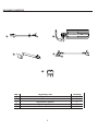
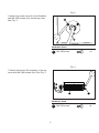
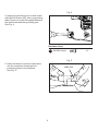
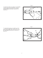
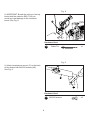
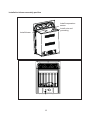
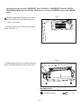
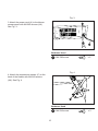
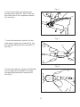
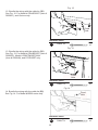
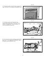
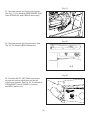
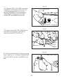
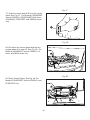
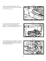
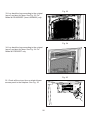
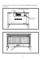
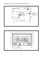
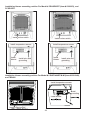
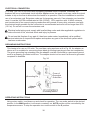
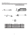
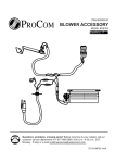
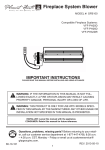
ITEM #0293809 BLOWER ACCESSORY
MODEL #QEB100
Español p. 35
Questions, problems, missing parts? Before returning to your retailer, call our
customer service department at 1-877-886-5989, 8:00 a.m - 4:30 p.m., EST,
Monday - Friday or e-mail [email protected].
PC-FANQEB-1104
PACKAGE CONTENTS
A
B
D
C
E
PART
A B C D E
DESCRIPTION
Power Cord
Blower
Temperature Sensor
Connector Wires
Rocker Switch
2
Quantity
1
1
1
1
1
HARDWARE CONTENTS
Part Description Quantity
AA
M4.2X8 Screw
10
BB
Cable Tie
2
Picture
(Shown to size)
Not shown to size
WARNINGS AND CAUTIONS
WARNING
• Read all instructions and warnings carefully before starting installation. Failure to follow these
instructions may result in a possible electric shock, fire hazard and will void the warranty.
• Read all instructions before using this appliance.
• If possible always unplug this appliance when not in use.
• Do not operate any heater with a damaged cord or plug or after the appliance malfunctions,
has been dropped or damaged in any manner.
• Any repairs to this appliance should be carried out by a qualified service person.
• Under no circumstances should this appliance be modified. Parts having to be removed for
servicing must be replaced prior to operating this appliance again.
• Do not use outdoors.
• Never locate this appliance where it may fall into a bathtub or other water container.
• Do not run cord under carpeting. Do not cover cord with throw rugs, runners or the like.
Arrange cord away from traffic areas and where it will not be tripped over.
• To disconnect this appliance, turn controls to the off position, then remove plug from outlet.
• Connect to properly grounded outlets only.
• This appliance, when installed must be electrically grounded in accordance with local codes,
with the current CSA C22.1 Canadian Electrical codes or for USA installations, follow local
codes and the National Electric Code, ANSI/NFPA No. 70.
• Do not insert or allow foreign objects to enter any ventilation or exhaust opening as this may
cause an electric shock, fire or damage the appliance.
• To prevent possible fire, do not block air intakes or exhaust in any manner.
• Use this appliance only as described in this manual. Any other use not recommended by the
manufacturer may cause fire, electric shock or injury to persons.
• Avoid the use of an extension cord because of the risk of overheating the cord and the risk
of fire. Extension cords are for temporary use only. If an extension cord must be used, it
must be UL/CSA certified, rated at 10A (1250W), 125V maximum with 16 AWG minimum and
constructed of two current carrying conductors with ground. A heavy duty extension cord with
the shortest length possible for the connection is recommended and must not be longer than
50 ft. (15.2 m). Do not coil or cover the extension cord.
3
PREPARATION
Before beginning assembly of product, make sure all parts are present. Compare parts with
package contents list. If any part is missing or damaged, do not attempt to assemble the
product. Contact customer service for replacement parts.
Estimated Assembly Time: 60 minutes
Tools Required for Assembly: Philips Screwdriver and Wire Cutter
ASSEMBLY INSTRUCTIONS
This blower contains assembly instructions for the following models and item numbers
CRHED200TA3 (Item # 0328247), and ED series.
For the CRHQD250T (Item # 0293811), CRHSD25RT (Item # 0328253), CRHFD400RT-M-M
(Item # 0328248), BD23 series, Q stove, PCSD25RT series and FBD400 series see
page 14 - 28.
Fig. 1
Before installing the blower, be certain
to turn off the unit, and allow time for
unit to cool down.
1. Unscrew and remove the top cover of the
fireplace. See Fig. 1.
4
Fig. 2
2. Attach the power cord (A) to the fireplace
with M4.2X8 screws (AA) on the top cover.
See Fig. 2.
AA
A
Hardware Used
AA
M4.2X8 screw
x3
Fig. 3
3. Attach the blower (B) assembly to the top
cover with M4.2X8 screws (AA). See Fig. 3.
B
AA
Hardware Used
AA
5
M4.2X8 screw
x4
Fig. 4
4. Attach the grounding port to shell board
with M4.2X8 screw (AA); refer to grounding
label. Be sure to insert the gasket between
the shell board and the grounding port.
See Fig. 4.
AA
Hardware Used
AA
M4.2X8 screw
x1
Fig. 5
5. Insert the blower connector (male port)
into the connector (female port) to
protecting jacket in the fireplace.
See Fig. 5.
Male
MalePort
port
Female
Female port
Port
6
Fig. 6
6. Insert the male port, which is on the black
power supply wire (marked P2), into the
corresponding female port (marked P2).
See Fig. 6.
Fig. 7
7. Insert the female port, which is on the
white power supply wire (marked P1), into the corresponding male port (marked P1).
See Fig. 7.
P1
7
Fig. 8
8. IMPORTANT: Bundle the wiring to the top board with the cable tie (BB). This is to
avoid any heat damage to the insulation
board. See Fig. 8.
BB
Hardware Used
BB
Cable Tie
x1
Fig. 9
9. Attach temperature sensor (C) to the back of the firebox with M4.2X8 screws (AA).
See Fig. 9.
C
AA
Hardware Used
AA
8
M4.2X8 screws
x2
Fig. 10
10. Insert the wires marked with AUTO, OFF and MAN into wire slot on the right
corner. Feed them as close to the bottom
as possible. See Fig. 10.
MAN
OFF
AUTO
Fig. 11
11. Connect two black and yellow wires (female ports) maked T1 and T2 with the
two male ports on the temperature sensor
(C). See Fig. 11.
T1
C
Fig. 12
12. Unscrew two screws on the grill. Remove
the grill and logs. See Fig. 12.
9
T2
Fig. 13
13. Unscrew the control panel (two screws).
Pull the control panel out without disconnecting
the ignitor wire. See Fig. 13.
Fig. 14
14. Feed the AUTO, OFF, MAN connectors
through the rocker switch hole on the left
of the control panel. See Fig. 14.
IGNITOR
Fig. 15
15. Connect the AUTO, OFF, MAN wires to
the three corresponding male tabs on the rocker switch (E). See Fig. 15.
AUTO
E
10
OFF
MAN
Fig. 16
16. Push the rocker switch (E) into the control
panel. See Fig. 16.
E
Fig. 17
17. Re-attach the control panel with the two
screws taken off in step 13. See Fig. 17.
Fig. 18
18. Lay the logs according to the original layout. Refer to manual for log layout.
See Fig. 18.
11
Fig. 19
19. Re-attach the grill with the two screws
taken off in step 12. See Fig. 19.
Fig. 20
20. Re-attach the top panel with the screws
taken off in step 1. See Fig. 20.
Fig. 21
21. Push the protection tab in to make it
embed into the surface of top cover.
Protection
Tab
Protection
Tab
12
Installation blower assembly position
Install temperature
sensor
Install wire and
grounding
Install blower
Install rocker switch
13
Instruction for the models CRHQD250T (Item # 0293811), CRHSD25RT (Item # 0328253),
CRHFD400RT-M-M (Item # 0328248), BD23 series, Q stove, PCSD25RT series and FBD400
series.
Fig. 1
Before installing the blower, be certain
to turn off the unit, and allow time for
unit to cool down.
1. Unscrew and remove the blower access
panel. See Fig. 1.
Fig. 2
2. Attach blower (B) onto the blower access
panel with M4.2X8 screws (AA). See Fig. 2.
B
AA
Hardware Used
AA
14
M4.2X8 screws
x4
Fig. 3
3. Attach the power cord (A) to the blower
access panel with M4.2X8 screws (AA).
See Fig. 3.
AA
A
Hardware Used
AA
M4.2X8 screw
x3
Fig. 4
4. Attach the temperature sensor (C) to the
back of the firebox with M4.2X8 screws
(AA). See Fig. 4.
C
AA
Hardware Used
AA
15
M4.2X8 screw
x2
Fig. 5a
5. Insert the wires marked with AUTO,
OFF and MAN into wire slot on the right
corner. Feed them as close to the bottom
as possible. See Fig. 5a and 5b (top view) Fig. 5c (top view) (For Model # PCSD25RT
only).
Fig. 5b
Fig. 5c
16
Fig. 6
6. Connect two black and yellow wires
(female ports) marked T1 and T2 with the
two male ports on the temperature sensor
(C). See Fig 6.
T1
T2
C
Fig. 7
7. Insert the female port, which is on the
white power supply wire (marked P1), into
the corresponding male port (marked P1).
See Fig. 7.
P1
Fig. 8
8. Insert the male port, which is on the black
power supply wire (marked P2), into the
corresponding female port (marked P2).
See Fig. 8.
17
Fig. 9
9. Insert the blower connector (male port)
into the connector (female port) to protecting
jacket in the fireplace. See Fig. 9.
Male
Male Port
port
Female port
Port
Fig. 10
10. Attach the grounding port to the tab on
the right side of the blower access hole
with M4.2X8 screws (AA). See Fig. 10.
Grounding Tab
Tab
AA
Hardware Used
AA
M4.2X8 screw
x1
Fig. 11
11. Push the grounding tab inwards
(approximately 60 degrees). See Fig. 11.
Grounding Tab
Tab
18
Fig. 12
12. Bundle the wiring with the cable tie (BB).
See Fig. 12. For Model # CRHQD250T (Item #
0293811), and Q stove only.
BB
Fixed
Hole
Hardware Used
BB
Cable Tie
x1
Fig. 13
13. Bundle the wiring with the cable tie (BB).
See Fig. 13. For Model # CRHSD25RT (Item #
0328253), Model # CRHFD400RT-M-M (Item # 0328248), and PCSD25RT only.
Fixed
Hole
Hardware Used
BB
Cable Tie
x1
Fig. 14
14. Bundle the wiring with the cable tie (BB).
See Fig. 14. For Model # BD23 series only.
Fixed
Hole
Hardware Used
BB
19
Cable Tie
x1
Fig. 15
15. Bundle the wiring with the cable tie (BB).
See Fig. 15. For Model # FBD400 series only.
Fixed
Hole
Hardware Used
BB
Cable Tie
x1
Fig. 16
16. Unscrew two screws on the grill. Remove
the grill and logs. See Fig. 16. For Model #
CRHQD250T (Item # 0293811), Q stove, and BD32 series only.
Fig. 17
17. Rotating handle, open the door, remove the
logs. See Fig. 17. For Model # CRHSD25RT (Item # 0328253),
20
Fig. 18
18. Rotating handle, open the door, remove the
logs. See Fig. 18. For Model # PCSD25RT only.
Fig. 19
19. Unscrew screws for fixing front log
bracket and Control Panel. See Fig. 19. For
Model # CRHQD250T (Item # 0293811), Q
stove, and BD32 series only.
Fig. 20
20. Unscrew the screws for fixing control panel.
See Fig. 20. For Model # CRHSD25RT (Item #
0328253), and PCSD25RT only.
21
Fig. 21
21. Unscrew screws for fixing control panel.
See Fig. 21. For Model # CRHFD400RT-M-M
(Item # 0328248), and FBD400 series only.
Fig. 22
22. Unscrew screws for fixing the door. See
Fig. 22. For Model # BD23 series only.
Fig. 23
23. Feed the AUTO, OFF, MAN connectors
through the rocker switch hole on the left
of the control panel. See Fig. 23. For Model #
CRHQD250T (Item # 0293811), Q stove, and BD32 series only.
22
Fig. 24
24. Feed the AUTO, OFF, MAN connectors
through the rocker switch hole on the left
of the control panel. See Fig. 24. For
Model # CRHSD25RT (Item # 0328253), CRHFD400RT-M-M (Item # 0328248),
PCSD25RT, and FBD400 series only.
Fig. 25
25. Connect the AUTO, OFF, MAN wires to
the threee corresponding male tabs on
the rocker switch (E). See Fig. 25.
AUTO
E
Fig. 26
26. Push the rocker switch (E) into the control
panel. See Fig. 26. For Model # CRHQD250T
(Item # 0293811), Q stove, and BD32 series
only.
E
23
OFF
MAN
Fig. 27
27. Push the rocker switch (E) into the control
panel. See Fig. 27. For Model # CRHSD25RT
(Item # 0328253), CRHFD400RT-M-M (Item
# 0328248), PCSD25RT, and FBD400 series
only.
E
Fig. 28
28. Re-attach the control panel with the two
screws taken off in step 16. See Fig. 28. For
Model # CRHQD250T (Item # 0293811), Q
stove, and BD32 series only.
Fig. 29
29. Re-fix Control Panel. See Fig. 29. For
Model # CRHSD25RT (Item # 0328253), and
PCSD25RT only.
24
Fig. 30
30. Re-fix Control Panel. See Fig. 30. For
Model # CRHFD400RT-M-M (Item # 0328248),
and FBD400 series only.
Fig. 31
31. Lay the logs according to the original
layout. Refer to manual for log layout.
See Fig. 31. For Model # CRHQD250T (Item #
0293811), Q stove and BD32 series only.
Fig. 32
32. Lay back the logs according to the original
layout, and shut the door. See Fig. 32. For
Model # CRHFD400RT-M-M (Item # 0328248),
and FBD400 series only.
25
Fig. 33
33. Lay back the logs according to the original
layout, and shut the door. See Fig. 33. For
Model # CRHSD25RT (Item # 0328253) only.
Fig. 34
34. Lay back the logs according to the original
layout, and shut the door. See Fig. 34. For
Model # PCSD25RT only.
Fig. 35
35. Check all the wires, then re-attach blower
access panel to the fireplace. See Fig. 35
26
Installation blower assembly position For Model # CRHQD250T (Item # 0293811),
and Q stove.
Install blower
Install temperature sensor
Install wire and
grounding
Install rocker switch
27
Installation blower assembly position For Model BD23 series
Install temperature sensor
Install wire
and
grounding
Install blower
Install rocker switch
28
Installation blower assembly position For Model # CRHSD25RT (Item # 0328253), and
PCSD25RT.
Install rocker switch
Install rocker switch
Install temperature sensor
Install temperature sensor
Install blower
Install blower
Install wire and
grounding
Install wire and
grounding
Installation blower assembly position For Model # CRHFD400RT-M-M (Item # 0328248),
and FBD400
Install temperature sensor
Install
grounding
Install blower
Install rocker switch
29
ELECTRICAL CONNECTION
A 15 amp, 120 Volt, 60 Hz circuit with a properly grounded outlet is required. Preferably, the
fireplace will be on a dedicated circuit as other appliances on the same circuit may cause the circuit
breaker to trip or the fuse to blow when the heater is in operation. Plan the installation to avoid the
use of an extension cord. Extension cords are for temporary use only. If an extension cord must be
used, it must be UL/CSA certified,rated at 10A (1250W), 125V maximum with 16 AWG minimum
and constructed of two current carrying conductors with ground. A heavy duty extension cord with
the shortest length possible for the connection is recommended and must not be longer than 50 ft.
(15.2 m). Do not coil or cover the extension cord.
Electrical outlet wiring must comply with local building codes and other applicable regulations to
reduce the risk of fire, electrical shock and injury to persons.
Do not use this fireplace if any part of it has been under water. Immediately call a qualified
service technician to inspect the fireplace and replace any part of the electrical system which
has been under water.
GROUNDING INSTRUCTIONS
This heater is for use on 120 volts. The cord has a plug as shown at A in Fig. 36. An adapter as
shown at C is available for connecting three-blade grounding-type plugs to two-slot receptacles.
The green grounding lug extending from the adapter must be connected to a permanent ground
such as a properly grounded outlet box. The adapter should not be used if a three-slot grounded
receptacle is available.
Fig. 36
Cover of
Grounded
Outlet Box
Grounding Pin
Metal Screw
Adapter
Grounding Means
OPERATING INSTRUCTIONS
Using rocker switch, turn blower on and check for operation. Turn on rocker switch to the desired
position. In the MAN position it will remain constantly on. AUTO position will be controlled by the
temperature sensor. To stop the operation turn rocker switch to the O position.
30
ELECTRICAL WIRING DIAGRAM
Any electrical re-wiring of this appliance must be done by a qualified electrician. This wiring must
be done in accordance with local codes and/or in Canada with the current CSA C22.1 Canadian
Electrical Code, and for US installations, the National Electrical Code ANSI/NFPA NO 70.
If repairing or replacing any electrical component or wiring, the original wire routing, color
coding and securing locations must be followed.
WHITE
GREEN
BLACK
BLACK
1. Power Cord
2. Bushing Strain Relief
3. Fan
4. Temperature Limiter
5. Rocker Switch
RED
FAN
CARE AND MAINTENANCE
Always disconnect the appliance from the main power supply and allow it to cool before
any servicing operation.
The motors used on the fan heater and flame blower are pre-lubricated for extended bearing life
and require no further lubrication. However, periodic cleaning/vacuuming of the appliance around
the air intake and exhaust, as well as the fan heater is recommended. For heavy or continuous
use, periodic cleaning must be done more frequently. If the heater blows alternating cold and
warm air, check the fan for free movement and for debris restricting air flow. If the fan does not
move freely, the unit must be turned off and the fan replaced immediately in order to prevent
further damage to the unit.
31
REPLACEMENT PARTS
NOTE: Use only original replacement parts. This will protect your warranty coverage for parts
replaced under warranty.
PARTS UNDER WARRANTY
Call Customer Service toll free at (1-877-886-5989) for referral information.
When calling Customer Service, have ready:
•
Your name
•
Your address
•
Model and serial number of your heater
•
How heater was malfunctioning
•
Type of gas used (Propane/LP or Natural gas/NG)
•
Purchase date
•
Usually, we will ask you to return the defective part to the factory
PARTS NOT UNDER WARRANTY
Call Customer Service toll free at (1-877-886-5989) for referral information.
When calling Customer Service have ready:
•
Model number of your heater
•
The replacement part number
32
REPLACEMENT PARTS LIST
For replacement parts, call our customer service department at 1-877-886-5989,
8:00 a.m - 4:30 p.m., EST, Monday - Friday or e-mail [email protected].
A
B
D
C
E
PART
A B C D E
PART NUMBER
XB001-01
XB002-01Q
XB003-01
XB004-01Q
PF06-0400-A
DESCRIPTION
Power Cord
Blower
Temperature Sensor
Connect Wire
Rocker Switch
33
Quantity
1
1
1
1
1
WARRANTY INFORMATION
Keep This Warranty
IMPORTANT: We urge you to fill your warranty registration card within TEN(10) days of date
of installation, complete with the entire serial number which can be found on the rating plate.
Retain this portion of the card for your record.
Always specify model and serial numbers when communicating with customer service.
We reserve the right to amend these specifications at any time without notice. The only
warranty applicable is our standard written warranty. We make no other warranty, expressed
or implied.
LIMITED WARRANTY:
PRO-COM warrants this product to be free from defects in materials and components for TWO
(2) years from the date of first purchase, provided that the product has been properly installed,
operated and maintained in accordance with all applicable instructions, to make a claim under
this warranty, the Bill of Sale or cancelled check must be presented.
RESPONSIBILITY OF OWNER
This warranty is extended only to the original retail purchaser. This warranty covers the cost
of part(s) required to restore this heater to proper operating condition and an allowance for
labor when provided by a PRO-COM Authorized Service Center. Warranty part(s) MUST be
obtained through authorized dealers of this product and/or PRO-COM who will provide original
factory replacement parts. Failure to use original factory replacement parts voids this warranty.
The heater MUST be installed by a qualified installer in accordance with all local codes and
instructions furnished with the unit.
WHAT IS NOT COVERED
This warranty does not apply to parts that are not in original condition because of normal
wear and tear or parts that fail or become damaged as a result of misuse, accidents, lack of
proper maintenance or defects caused by improper installation. Travel, diagnostic cost, labor,
transportation and any and all such other costs related to repairing a defective heater will be
the responsibility of the owner.
TO THE FULL EXTENT ALLOWED BY THE LAW OF THE JURISDICTION THAT GOVERNS
THE SALE OF THE PRODUCT, THIS EXPRESS WARRANTY EXCLUDES ANY AND
ALL OTHER EXPRESSED WARRANTIES AND LIMITS THE DURATION OF ANY AND
ALL IMPLIED WARRANTIES. INCLUDING WARRANTIES OF MERCHANTABILITY AND
FITNESS FOR A PARTICULAR PURPOSE TO TWO (2) YEARS ON ALL COMPONENTS
FROM THE DATE OF FIRST PURCHASE. PRO-COM'S LIABILITY IS HEREBY LIMITED
TO THE PURCHASE PRICE OF THE PRODUCT AND PRO-COM SHALL NOT BE LIABLE
FOR ANY OTHER DAMAGES WHATSOEVER INCLUDING INDIRECT. INCIDENTAL OR
CONSEQUENTIAL DAMAGES.
Some states do not allow a limitation on how long an implied warranty lasts or an exclusion or
limitation of accidental or consequential damages, the above limitation on implied warranties,
or exclusion or limitation on damages may not apply to you.
This warranty gives you specific legal right, and you may also have other rights that vary from
state to state.
Printed in China
34