1
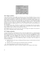
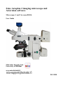
Zeiss Axioplan 2 imaging microscope and
Axiovision software
Microscopes 1 and 2 in room B501b
User Guide
Molecular Imaging Unit
University of Helsinki
www.miu.helsinki.fi
20.5.2010
1
GENERAL ......................................................................................................................... 1
1.1................................................................................................................... Instrument
1.2.................................................................................................................Reservations
1.3.......................................................................................................... Unauthorized use
1.4......................................................................................................... Users’ mailing list
1.5................................................................................................................... User guide
1.6..................................................................................................... Acknowledging MIU
1.7........................................................................................................ Sample preparation
1.7.1 .......................................................................................Selection of fluorochromes
1.7.2 .................................................................................................. Mounting samples
1.8......................................................................................... Image processing and analysis
2
TURNING ON THE EQUIPMENT ................................................................................ 2
2.1............................................................................... Zeiss Axioplan 2 imaging microscope
2.2............................................................................... Light source for fluorescence imaging
2.3.......................................................................... Light source for transmitted light imaging
2.4.................................................................................................... Axiocam HRc camera
3
6
7
8
2
3
4
4
LIGHT PATHS ................................................................................................................. 5
3.1..........................................................................................Shutters for fluorescence light
3.2..................................................................................................................... Push rods
4
5
1
1
1
1
1
1
2
2
2
2
5
6
FILTERS ........................................................................................................................... 6
OBJECTIVES ................................................................................................................... 8
5.1.............................................................................................. List of objectives available
5.2............................................................................................................... Oil objectives
5.2.1 ..................................................................... Changing between oil and air objectives
5.2.2 .............................................................................................................. Oil usage
5.2.3 ............................................................................................ Cleaning oil objectives
8
9
9
10
10
8.1....................................................................................................................... Settings
8.2...................................................................................................... Bright-field imaging
8.3................................................................................................... Phase contrast imaging
8.4................................................................................................................ DIC imaging
8.5.............................................................................. The auxiliary lens for transmitted light
8.6....................................... Optimal settings for transmitted light imaging (Köhler illumination)
12
13
13
13
14
14
10.1 ............................................................................................. Zeiss Axiovision software
10.2 .................................................................................................................. Live view
10.3 .............................................................................................. Acquiring a single image
10.4 ............................................................................................................ Exposure time
10.5 ............................................................................................................. White balance
10.6 ......................................................................................................... Image resolution
10.7 ....................................................................................................... Display properties
10.8 ............................................................................................... Acquiring multiple dyes
10.9 .......................................................................................................... Z-stack imaging
15
15
16
16
17
18
18
19
20
PLACING THE SAMPLE ............................................................................................. 10
FOCUSING ..................................................................................................................... 11
CONTRASTING METHODS FOR TRANSMITTED LIGHT IMAGING ............. 12
9 ADJUSTING THE OCULARS...................................................................................... 15
10 ACQUIRING IMAGES.................................................................................................. 15
11 POST PROCESSING ..................................................................................................... 21
11.1 ........................................................................................... Scalings and measurements
11.2 .......................................................................................................Shading correction
21
21
12.1 ............................................................................................................ Saving images
12.2 .................................................................................. Transferring images over network
12.2.1 ............................................................................................ Using MCBSERVER
12.2.2 ................................................................... Transferring directly to a Mac computer
21
22
22
22
15.1 ............................................................................................................. Software help
24
12 SAVING AND TRANSFERRING IMAGES ............................................................... 21
13 EXPORTING IMAGES ................................................................................................. 22
14 ENDING YOUR IMAGING SESSION ........................................................................ 23
15 TROUBLESHOOTING ................................................................................................. 24
15.2 .................................................................................................................. Computer
15.3 ................................................................................................................ Microscope
15.3.1 .............................................................................................................. General
15.3.2 ................................................................................ Fluorescence light microscopy
15.3.3 ................................................................................. Transmitted light microscopy
15.3.4 .............................................................................................................. Camera
24
25
25
25
25
25
1 General
1.1 Instrument
This user guide covers the use of Zeiss Axioplan 2 imaging microscope. For more information on
each instrument, visit: http://www.miu.helsinki.fi/instruments/index.htm.
1.2 Reservations
Instructions for Scheduler online reservation system can be found on the MIU web page:
http://www.miu.helsinki.fi/reservations.htm. You can make your reservations three weeks in
advance. If you need to cancel your reservation, you have to do it two hours before your reservation
starts. Make sure you are familiar with the use of Scheduler and the MIU user policy and fees
(http://www.miu.helsinki.fi/userinfo.htm and http://www.miu.helsinki.fi/fees.htm).
If you want to extend your session and there are no reservations after you, you can use the "extend"
option in Scheduler (click first on your reservation). If your reserved time is already up, you cannot
extend your present reservation any more. In this case you will have to make a new reservation.
1.3 Unauthorized use
MIU periodically checks the logins of the computers. If your logon/off times exceed your reserved
time in Scheduler, MIU will consider that as unauthorized use of the instrument and ask for an
explanation. For unauthorized use of the instrument, MIU may issue a warning. After three
warnings, MIU may revoke the user's license. Also, misuse/neglect of the instrument may lead
either to a warning or cancellation of the user license, and the repair costs may be charged.
1.4 Users’ mailing list
All registered users are automatically added to the users‟ mailing list. Please read the e-mails, as
there might be changes in the configuration or other relevant information.
1.5 User guide
This user guide will be continuously updated by the MIU personnel. Check that you have the latest
version of the user guide: go to http://www.miu.helsinki.fi/instruments/ and compare the date of the
latest update with the date on the first page of your printed user guide. This is the only place for
update announcements; no e-mails about updates will be sent.
The user guide can also be read online: http://www.miu.helsinki.fi/instruments/.
1.6 Acknowledging MIU
Whenever you are using instruments and/or services maintained/provided by MIU, you are
expected to acknowledge MIU in your publications and inform MIU about the papers.
1
1.7 Sample preparation
1.7.1
Selection of fluorochromes
If you want to achieve the best possible resolution, use a fluorochrome whose emission spectrum is
covering as short wavelengths as possible. The resolution of the microscope is determined by the
numerical aperture (NA) of the objective used and the wavelength of the light detected. The larger
the NA, and the shorter the wavelength, the better the resolution.
For thick tissues, image acquisition deeper in the tissue is often a problem because of light
scattering in the tissue. The longer the wavelength of the light, the less it scatters, and the better its
penetration into tissues. Thus, use fluorochromes whose emission spectra are in the far-red region if
you need to image deep inside tissue.
For multilabel imaging, select fluorochromes that are spectrally wide apart. E.g. Alexa488 and
Alexa594 usually have cross-talk between channels if imaged simultaneously, so they should be
imaged sequentially.
1.7.2
Mounting samples
You should either use a mounting medium that will harden or, in the case of non-hardening one,
seal the edges of the cover glass with nail polish or some other sealant. Let the sealant dry well
before you come to the microscope - nail polish is one of the most harmful substances for optics.
Also, unsettled mounting medium, or one containing too much water (slides not dry enough when
mounted), or too much mounting medium, can affect imaging by causing shadows and/or stripes in
the image.
If you are using oil immersion objectives, the refractive index of the mounting medium used should
be close to the refractive index of the immersion oil (1.518). For more information on mounting
media and antifade reagents, visit: http://www.uhnresearch.ca/facilities/wcif/PDF/Mountants.pdf.
Most of the objectives are designed for coverslip thickness 0.17 mm, which corresponds to number
1.5 coverslips.
1.8 Image processing and analysis
MIU has two Imaging Workstations that have software for further image processing and analysis,
such as deconvolution, cell counting, and more. Visit the MIU web site or contact MIU for more
information. Use of Imaging Workstations is free of charge, and MIU staff gives training and help
with the software. MIU also provides customized image analysis tools in case the commercial and
free software do not satisfy your image analysis needs.
2 Turning on the equipment
2.1 Zeiss Axioplan 2 imaging microscope
The main power switch of the microscope (Figure 1) is the green switch located on the right side of
the microscope.
2
Figure 1. Zeiss Axioplan microscope.
2.2
Light source for fluorescence imaging
In case you want to use fluorescence light and it is not already on, check in the paper calendar when
the fluorescence light was turned off. Remember that you have to wait for at least 30 min before
you can turn the fluorescence light on after it has been turned off. If you do not wait long enough,
you risk of damaging the fluorescence bulb, which can explode releasing hot gaseous mercury.
Turn the mercury light on by pressing the button on the power supply that is on the shelf (Figure 2).
It takes a moment before the bulb will actually be lit.
Make sure you know the rules that determine when you should turn off the fluorescence light and
when to leave it on after using the microscope (see "Ending your imaging session", p. 23). You
should also know what else to do when turning off the mercury lamp.
Figure 2. Power supply of the fluorescence lamp.
3
2.3 Light source for transmitted light imaging
The black round button labeled “HAL” for the halogen light source is on the right side of the
microscope (Figure 3, arrow 1). Voltage of the halogen light can be adjusted with a knob (Figure 3,
arrow 2). Remember that while the change of the voltage changes the intensity of the light, it also
changes the color: a hot lamp burns bright and blue; a cool lamp burns dim and red. With neutraldensity filters it is possible to adjust light intensity without changing the color temperature. There
are two neutral-density filter wheels (Figure 3, arrow 3) that can be combined.
Figure 3. Power supply of the halogen lamp.
2.4 Axiocam HRc camera
Turn the camera on by plugging the power cable in (Figure 4). Green light indicates that the camera
is on. Alternating green and red lights means that imaging is in progress.
4
Figure 4. Back side of the Zeiss Axiocam HRc camera
3 Light paths
3.1
Shutters for fluorescence light
There are two shutters (Figure 5) which prevent light from mercury lamp from passing to the
specimen: a mechanical shutter (1) and an electronic shutter (2). The mechanical shutter blocks
light when it is pushed in. The electronic shutter opens and closes by turns when the button labeled
“FL” is pressed. Check that the “HAL” button for transmitted light is not pressed when imaging
fluorescence. If the buttons do not respond, power off and on the microscope.
Figure 5. Shutters for the light from mercury lamp.
5
3.2
Push rods
There are two push rods near the oculars (Figure 6). The rod on the right (1) is for camera/ocular
selection. The rod on the left (2) prevents light from passing through the oculars.
Rod
IN
MIDDLE
OUT
1
Oculars 100 %
Oculars 50 %
Oculars 0 %
Camera 0 %
Camera 50 %
Camera 100 %
2
Oculars closed
Oculars open
Figure 6. Push rods for camera/ocular selection (1) and for blocking the oculars (2).
4 Filters
There are seven fluorescence filters in the microscope. The filter position can be seen in the small
window (Figure 7). Position 8 is used for transmitted light.
6
Table 1. Microscope filter configurations.
Microscope 1
Microscope 2
1
DAPI (Semrock 5060B)
1
DAPI (Semrock 5060B)
2
FITC (Chroma 41001)
2
FITC (Chroma 41001)
3
TRITC (Chroma 41002b)
3
TRITC (Chroma 41002b)
4
Texas Red (Chroma 41004)
4
Texas Red (Chroma 41004)
5
Narrow GFP (Chroma 41020)
5
DAPI /FITC/TRITC (Zeiss 25HE)
6
CFP (Zeiss 47HE)
6
Narrow GFP (Chroma 41020)
7
YFP (Zeiss 46HE)
7
Yellow GFP (Chroma 41028)
8
Transmitted light
8
Transmitted light
Figure 7. Fluorescence filter position.
The filter position can be changed using the buttons on the left side of the microscope, under the
focus wheel, or through software by clicking the corresponding reflector in MICROSCOPE /
REFLECTED (Figure 8).
7
Figure 8. Buttons for changing filter position.
Make sure that you are using a filter that matches the spectral properties of the fluorochromes in
your sample. The web page of the instrument contains the links to the spectral information of each
filter.
The triple filter in microscope 2 is not intended for imaging. Instead, for multilabel imaging, use the
multidimensional acquisition with individual filters for each label.
5 Objectives
5.1 List of objectives available
There are six objectives in the microscopes:
Microscope 1
Mag.
Type
Working
distance
(mm)
Numerical
Aperture
(N.A.)
Immersion
medium
Phase ring DIC
position
position
10x
Plan-Neofluar
5.6
0.3
air
Ph1
20x
EC Plan-Neofluar
2.0
0.5
air
Ph2
DIC II
40x
EC Plan-Neofluar
0.71
0.75
air
Ph2
DIC II
63x
Plan-Neofluar
0.1
1.25
oil
63x
Plan-Neofluar
0.1
1.25
oil
Ph3
100x
Plan-Neofluar
0.2
1.3
oil
Ph3
8
DIC III
DIC III
Microscope 2
Mag.
Type
Working
distance
(mm)
Numerical
Aperture
(N.A.)
Immersion
medium
5x
Plan-Neofluar
13.6
0.15
air
10x
Plan-Neofluar
5.6
0.3
air
20x
EC Plan-Neofluar
2.0
0.5
air
40x
EC Plan-Neofluar
0.21
1.3
oil
63x
Plan-Apochromat
0.19
1.4
oil
100x
Plan-Neofluar
0.2
1.3
oil
Phase ring DIC
position
position
Ph3
DIC III
Objectives can be changed using the buttons on the right side of the microscope or through software
by clicking the corresponding icon in MICROSCOPE / COMMON (Figure 9).
Figure 9. Buttons for changing the objective.
5.2 Oil objectives
5.2.1
Changing between oil and air objectives
When you change between objectives, make sure you never change to an air objective while still
having oil on the sample. The air objectives are extremely difficult to clean after being smeared
with oil.
9
5.2.2
Oil usage
Only Zeiss F 158 immersion oil should be used with oil objectives. There are brown oil bottles on
the table between the microscopes 1 and 2. Lower the stage to “load position” for more room to
operate with oil by pressing the button A in the Figure 10. Drop a small amount of oil on the cover
glass. Bring the stage back to the previous level “work position” with the button B in the Figure 10.
Figure 10. Stage movement buttons
5.2.3
Cleaning oil objectives
After the imaging session clean up tables, stages, and especially the objectives; have the lights
turned on so that you can see properly. Use cotton swabs immersed in ethanol (take from the correct
bottle) to clean oil from objectives. After this, dry with a clean swab. Start the wiping in the middle
of the lens and move outwards in a spiral way. You can also use lens paper to first wipe up most of
the oil. If you use lens paper, do not rub it against the top lens of the objective. There are two
ethanol bottles; one is only for cleaning objectives, the other for cleaning tables, the stage etc. in
case there are oil spills.
6 Placing the sample
Place your sample on the specimen stage by manually widening and releasing the spring-operated
object holder (Figure 11, part a). To move the specimen stage in the XY-direction turn the two
adjustment wheels connected to the stage on the right-hand side (Figure 11, part c). Upper wheel
controls the movement in y-direction (back and forth), lower in x-direction (side to side). If you
need to rotate the stage to get the image in any wanted angle, open the rotation lock by unscrewing
it and then rotating the stage by hand (Figure 11, part b). Re-screw the lock after use!
10
Figure 11. Stage functions
7 Focusing
There are focusing knobs on both sides of the microscope. The outer wheel is for coarse adjustment
and the inner wheel is for fine adjustment. The actual speed of the stage depends on the
magnification of the objective.
There is a programmable limit which prevents focusing too close to the sample. When the limit has
been reached the “beep” sound can be heard. Sometimes the limit might be set incorrectly. The limit
can be overridden by pressing the button on the left side of the microscope (Figure 12). Keep the
button pressed and focus. The new limit will be set when the button is released.
11
Figure 12. The button for overriding the focusing limit.
8 Contrasting methods for transmitted light imaging
8.1
Settings
Each contrasting method requires a matching position of the condenser. Condenser position can be
changed with buttons on the condenser (Figure 13, 1) or within the software. The current position
can be seen in the opening (Figure 13, 2). Arabic numbers 1, 2 and 3 are for phase contrast imaging
and Roman numbers I, II and III are for DIC-imaging. Contrasting method settings can also be seen
with software in MICROSCOPE / TRANSMITTED.
12
Figure 13. Buttons for changing the condenser position (1) and an opening to view the current
position (2).
There are predefined settings for each contrasting method and objective in software in TOOLS /
SETTINGS / WORKGROUP. When choosing a certain setting, the objective will be changed and
the condenser will be adjusted automatically.
8.2
Bright-field imaging
Bright-field imaging is usually used for histologically stained specimen, but sometimes unstained
specimen can also be observed. All objectives are suitable for bright-field imaging. To do brightfield imaging, the condenser should be in position „I/H‟.
8.3
Phase contrast imaging
Only certain objectives (marked with Ph) are suitable for phase contrast imaging. The Ph-value
written on the objective and the condenser position value should match (Arabic numerals for phase
contrast). Change the condenser position with the button showed on Figure 13 part 1. Make sure the
Köhler illumination (Chapter 8.6) is done properly and the condenser diaphragm is open enough
(rightmost button on Figure 13). If you want to increase contrast on phase contrast images, use the
green filter under the condenser (the filter looks yellow).
8.4
DIC imaging
Currently there are no analyzers installed in either of the Axioplans, and therefore DIC imaging
cannot be done.
13
8.5 The auxiliary lens for transmitted light
The button to control the auxiliary lens is right above the contrasting method indicator (number 2 in
Figure 13). The lens should be used when imaging with all but the 5x objective. If the auxiliary lens
is in the wrong position, it is impossible to do the Köhler illumination (Chapter 8.6).
8.6 Optimal settings for transmitted light imaging (Köhler illumination)
To achieve optimal image quality some adjustments should be made before imaging. Köhler
illumination needs to be adjusted in the beginning of every transmitted light imaging session. The
elevation and the centering of the condenser can be optimized as follows (Figure 14, the numbers in
the list refer to the arrows in the image):
Select a 10x objective
Select condenser position I/H
Focus on the specimen
Bring the condenser to the uppermost position (2)
Close luminous field diaphragm (1) until the small hole can be seen in oculars
Focus the diaphragm image by moving the condenser (2)
Use centering screws (3) to move diaphragm to the center
Open luminous field diaphragm (1) until its edges disappear from the field of view
Figure 14. Adjusters for field diaphragm (1), condenser elevation (2) and condenser centering
(3).
14
9 Adjusting the oculars
Make sure that the oculars are correctly adjusted for your eyes. If you have normal vision, the zero
mark on the sides of the oculars should match the white dot. If you wear eyeglasses but want to use
the microscope without them, you must adjust the oculars according to your vision. First look at
your specimen with your right eye closed (through the left ocular). Slowly turn the eyepiece scale
ring until the image is optimally in focus. Repeat with the other eye. The scale on the oculars is the
diopter scale.
10 Acquiring images
10.1 Zeiss AxioVision software
The computer and the monitors may be turned off. Turn them on if image acquisition is needed.
Log on to the computer with your personal HYAD-username. Choose „Log on to ATKK‟. Start the
software by clicking the AxioVision-icon on the desktop. The microscope and camera should be
turned on before starting the software as the devices are recognized only during startup. You can
access the online help by pressing F1 in the software.
Before acquiring images, the setting for auto save folder should be changed. In the main window,
go to TOOLS / OPTIONS… / STORAGE and write “H:\” in the field. If you leave this empty,
temporary images during acquisition will be saved in your personal profile which has a limited
storage space. Large images fill up the profile quickly and error messages will pop up.
10.2 Live view
Enable real-time video by clicking the LIVE-button in software (Figure 15). It may be practical to
drag the live-window to the secondary display and maximize it there.
Figure 15. Live-button in AxioVision software.
The refresh rate of live image can be adjusted (Figure 16). Quality of live image depends on the
refresh rate. However, this setting has no influence on the actual image that will be taken. There are
three options for the refresh rate:
slow (good quality)
medium (medium quality)
fast (poor quality)
By right clicking the live image with right mouse button you can access more options, such as
zooming in and out in the image, etc.
15
Figure 16. Refresh rate settings for live image.
10.3 Acquiring a single image
A single image can be acquired by clicking the snap-button (Figure 17). The new image will open
in a new window.
Figure 17. Snap-button in Axiovision software.
10.4 Exposure time
Click AxioCamHR in the Work area menu (Figure 18) and choose ADJUST tab (Figure 19). There
are three ways of adjusting the time of exposure:
manually, either with a slider or by entering the numeric value
by clicking MEASURE, the software estimates the suitable time of exposure
by choosing AUTOMATIC, the software estimates the time of exposure before each
snapshot
To prevent overexposure, check that the signal intensity histogram does not touch the right end of
the graph (the bright end). Over exposed pixels can be seen as red in the live window by clicking
the over exposure button (looks like a French flag). It will show underexposed pixels in blue.
16
Figure 18. Workarea menu
Figure 19. Exposure settings
10.5 White balance
White balance adjustment is not needed in fluorescence imaging because the illumination color
does not change. However, inappropriate white balance settings may lead to poor image quality. It
is recommended to choose 3200K for fluorescence imaging (Figure 20). Correct white balance
settings are essential when taking images with transmitted light. The color of halogen lamp depends
on voltage. The color turns from red to blue when voltage is increased. Human eye compensates for
the color variation but the camera should be adjusted properly. There are three options (Figure 20):
Interactive... = white balance will be adjusted according a sample in the image. Click a point
that should be white i.e. a place with just glass between the light source and sensor. This
setting is recommended if the Automatic setting does not work well.
3200K = white balance will be adjusted to color temperature 3200K (Maximum power of
halogen lamp). This setting does not usually work for transmitted light imaging.
Automatic = software estimates suitable white balance according to the image. Often works
well. If not, use the Interactive selection.
17
Figure 20. White balance settings
10.6 Image resolution
Click Camera and then AxioCamHR in the Work area menu. Choose FRAME tab. There is a list of
available camera resolutions for acquisition. Note that there are four options available for color
images: BIN, STANDARD, SCANNED and HIGH SPEED. STANDARD COLOR is faster to take
but SCANNED COLOR offers softer image quality, by removing noise. The HIGH SPEED modes
produce more noise, but they also retain any sharp edges the objects may have. When using BIN
resolutions, the pixel values are combined to create higher intensity values. For example a 2x2
binning will sum four neighboring pixels in to one. The resolution will halve, but the intensities are
four times higher.
The resolutions greater than 1300x1030 are produced by microscanning, where the sensor chip is
moved slightly between images and the resulting image is interpolated from multiple different
images. Both the image resolution and acquisition time increase.
With FRAME options you can also select only a part of the image to be acquired. The selection is
done with the configuration under resolution settings.
10.7 Display properties
Axiocam-camera detects 16384 intensity levels of each color channel. However, computer displays
typically can display only 128 to 256 levels. The way how 16384 levels are mapped to the display
can be adjusted. Click the image with right mouse button and choose PROPERTIES (or press
ALT+ENTER). Then choose DISPLAY tab. Colored curves show the distribution of signal on
different color channels of an RGB image. The black curve describes how intensity levels are
shown on display. The curve can be modified by sliders or by mouse. There are buttons for
predefined adjustments:
BestFit shows the whole range excluding specified percentage of actual minimum and actual
maximum values
Min/Max shows the whole range from minimum intensity to maximum
Linear shows linearly the whole dynamic range of the camera
With SAVE and RESTORE –buttons it is possible to apply the same settings to other images.
18
Figure 21. Display mapping adjustments
10.8 Acquiring multiple dyes
Choose MULTIDIMENSIONAL ACQUISITION in the Work area menu and C tab for color
channel settings (Figure 22). Select the dye that best corresponds you fluorochrome from the dropdown list. The pseudo color for the channel will be automatically selected according to the dye, but
it can be changed manually. The actual filter is defined separately using HARDWARE SETTINGS
(Figure 23). Choose the filter that you need for the channel in DURING ACQUISITION… Choose
SHUTTER CLOSED in AFTER ACQUISITION…
Figure 22. Multidimensional acquisition channel settings
Figure 23. Hardware settings for multidimensional acquisition
19
By clicking MEASURE (Figure 24) the software estimates the suitable time of exposure and the
preview live window pops up (Figure 25). Adjust the time of exposure manually if needed and
choose OK. Note that exposure adjustment works slightly different from the live window – the
image will not get darker if you shorten the exposure time, but it will be noisier. The image
intensities are multiplied to fit the monitor - hence the noise.
Figure 24. Exposure time setting
Figure 25. Settings for time of exposure.
Add more channels by clicking DUPLICATE (Figure 23). Channels can be acquired either one
channel at the time using SNAP button, or automatically acquiring all channels by clicking START
button at the bottom of the window. Channels can be enabled and disabled by clicking the channel
number with the right mouse button.
10.9 Z-stack imaging
Z-stacks can be acquired by choosing MULTIDIMENSIONAL ACQUISITION/Z. It is possible to
define either the center point of the stack or start and end points. The number of slices can be
entered directly or by specifying the slice distance. OPTIMAL DISTANCE –button calculates the
correct distance according to the Nyquist theory. This is important, if you are going process your
stack with 3D-deconvolution software. Note that the correct dye should be selected in
MULTIDIMENSIONAL ACQUISITION/C so the optimal distance could be calculated correctly.
20
The AxioVision software is not able to use decimal numbers on the z slice thickness if the Windows
user language is not set to English as it cannot use “,” as a decimal separator. The language setting
is tied to the roaming user profile, so it depends on the user. To use decimal numbers in the z slice
thickness, change your language setting to English. If you need help with this, ask the MIU staff.
11 Post processing
11.1 Scalings and measurements
There are calibrated scalings for different objectives in the software. Scalings can be found in
MEASURE/SCALINGS. By choosing MEASURE/AUTOMATIC SCALING the correct scaling
will be added to the image automatically according to the objective.
Scalings can be exploited for drawing scale bars and measuring objects. A scale bar can be added
by clicking the scale bar icon. Color and style of the scale bar can be changed by clicking the scale
bar with right mouse button and choosing PROPERTIES/ATTRIBUTES.
There are various measurements available in MEASURE-menu. Data table of measurements can be
created by choosing MEASURE /CREATE DATA TABLE.
11.2 Shading correction
Irregular lighting can be corrected after acquisition with shading correction. Choose IMAGE
PROCESSING/ ADJUST/SHADING CORRECTION. There are two ways to carry out the shading
correction: taking a reference image or using auto-mode.
When using transmitted light the reference image could be an empty area of the slide. For
fluorescence light a clean polished surface of the region can be used. If you choose AUTO, then the
software calculates the reference image from the original image by low pass filtering.
12 Saving and transferring images
12.1 Saving images
Many scientific journals nowadays require that image data included in submitted manuscripts are
also sent in the native format, which contains all acquisition parameters (metadata). Thus, always
save your original images as Zeiss native ZVI format. All metadata is saved within the ZVI file.
Although AxioVision is not able to show all the metadata if you have acquired multidimensional
images, the metadata are still there. These can be found in the meta data xml if the image is
exported. The exposure times of different channels can be shown by annotating the image with
“exposure time”. You can also open the file in ImageJ on the workstations to access the metadata.
Drive H: is your personal local folder. Actually it is a link to the automatically created folder
D:\"your username". You can keep your images here at your own risk (no backups are taken!). It is
recommended to transfer images somewhere else after your imaging session.
21
Drive R: is your personal University network folder. You can access the same folder also from
other Windows computers on the campus when logging on with your HYAD-username. "My
Documents" is a link to the same folder.
You can save your images to USB memory stick. There is an extension cable at the table.
12.2 Transferring images over network
12.2.1 Using MCBSERVER
Drive I: is a network drive in Mcbserver1. You can save images temporarily to that folder and pick
them up using your own computer. The folder will be emptied weekly (usually Mondays). Images
older than two weeks will be deleted. Images-folder can be accessed in several ways (ask MIU
about the password):
Windows-network: Cancerbio / Snap Server 4400 (Mcbserver1) / Images
Samba share: smb://mcbserver1.hi.helsinki.fi/images
FTP: ftp://mcbserver1.hi.helsinki.fi/images/
12.2.2 Transferring directly to a Mac computer
You can save your images directly to your computer through the network. Only SMB-protocol is
supported, so it works with Windows and Mac OS X. Mac OS X computer can be added to “My
Network Places” in Windows as follows:
Mac OS X:
enable: System preferences / Sharing / Services / Windows sharing
Windows:
choose: My Network Places / Add a network place / Next /
If F-Secure firewall complains something, choose: Allow
Enter two backslashes + your Mac‟s IP-address + one backslash + folder‟s name, e.g.
\\128.214.???.???\folder
Pick up a name for the network place
13 Exporting images
Single images can be saved with FILE / SAVE AS… When saving multi channel images, it is
recommended to use FILE / EXPORT (Figure 26). In the export window it is possible to choose
which channels will be saved. By choosing GENERATE MERGED IMAGE the combination
image of all the channels will be created. If you plan to quantify the image data, do not check ANY
of the boxes under File type. It is recommended to always use the TIF file format.
If you are exporting for publication or presentation use, you may want to select the CONVERT TO
8-BIT to make the image more compatible with Adobe Photoshop and Microsoft products. If you
have added scale bars, text or measurements, choose BURN-IN ANNOTATIONS to include those
22
in the image. If you have adjusted the display mapping curves (Chapter 10.7) you can save them in
the exported image by selecting the APPLY DISPLAY MAPPINGS selection.
Figure 26. Settings for exporting images.
If you have multiple ZVI files you want to export you can use the “Batch >>” button to export them
all.
14 Ending your imaging session
When you have finished your imaging session you should:
Close the electronic fluorescence light shutter (chapter 3.1)
Log off from the computer
Clean objectives from oil if that was used
23
On working days (Mo-Fr) leave the equipment on if your reservation ends before 16:00. If your
reservation begins before 16:00 and ends after 16:00 and you are not present at 16:00, please leave
Axiovision software on to show that you will continue your imaging session.
If your session ends after 16:00 on a working day, or you are using Axioplan on Saturday, Sunday,
or a holiday, you should turn off the equipment unless somebody has a reservation after you. You
can check that by opening Internet Explorer. The default page of IE shows that day's reservations
for Axioplan.
When turning off the equipment, the following tasks should be carried out:
Turn off the fluorescence light
Disconnect the power cable from the camera
Turn off the microscope
Cover the microscope (not the lamp housing)
Write down the time in the paper calendar
15 Troubleshooting
15.1 Software help
NOTE: Help-command in AxioVision software (F1 or right side of the upper bar) is a useful tool to
get detailed information about AxioVision functions.
15.2 Computer
It‟s not possible to log on to the computer.
Use HYAD user name.
Choose „log on to ATKK‟.
I don‟t have HYAD-username.
You can get it from the user account office (A113b). The office is usually open Tuesdays
and Thursdays between 8.30 and 11.30 and between 12.00 and 15.45. The telephone number
is (09) 191 25629 and the email is [email protected].
„Profile full‟ error pops up.
Set the auto-save folder in AxioVision TOOLS/OPTIONS/STORAGE to “H:\”
Delete some files from your profile: C:\Documents and Settings\”your username”. Click the
white cross on the right side of the taskbar to see, which files are consuming the profile
most.
AxioVision crashes sometimes when closing an image window and unsaved images will be lost.
This is a bug in AxioVision and hopefully it will be fixed soon.
24
There seems to be a way to avoid the problem: it occurs only when many image windows
are open at the same time in cascade mode (windows partially one on the other). When
windows are maximized (e.g. by double clicking the upper bar), the software seems to
behave properly.
15.3 Microscope
15.3.1 General
Microscope beeps when I try to focus.
Check the focusing limit setting and override it if necessary (Chapter 7).
The microscope can‟t be controlled with the software.
Check that the microscope is on (chapter 2.1). If the microscope was turned on after starting
the software you should exit and restart the software.
15.3.2 Fluorescence light microscopy
Fluorescence lamp doesn‟t light up.
The bulb might be burnt, ask MIU to install a new one.
Fluorescence lamp is on but no light comes to the specimen.
Check that both shutters are open (chapter 3.1).
Check that the holder of the UV-protector in microscope 2 (orange plastic plate close to the
objectives) has been properly installed, otherwise it might block the light path.
Fluorescence light image is very noisy.
Check white balance settings (chapter 10.5).
15.3.3 Transmitted light microscopy
Light source for transmitted light doesn‟t light up.
Check if both switches for light source are on (chapter 2.3).
Check the voltage setting (chapter 2.3).
Try to turn the microscope off and then back on (chapter 2.1).
Transmitted light image is too red / too blue.
Check white balance settings (chapter 10.5).
15.3.4 Camera
It‟s not possible to acquire an image.
Check that the camera is on (chapter 2.3). If the camera was turned on after starting the
software you should exit and restart the software.
25