1
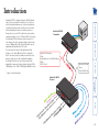
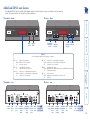
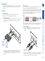
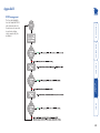
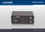
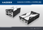
AdderLink XD522 User Guide Mounting......................................................................................9 Connections................................................................................10 Transmitter.............................................................................10 Video connections.............................................................10 USB connections................................................................10 Audio connections............................................................11 Serial connection...............................................................12 Link connections................................................................12 Power connection.............................................................13 Receiver..................................................................................14 Video display connections................................................14 USB connections................................................................15 Audio connections............................................................16 Serial connection...............................................................18 Link connections................................................................18 Power connection.............................................................19 Front panel indicators................................................................21 Operating Modes.......................................................................21 Using hotkeys.............................................................................22 The Dashboard.......................................................................22 Further information Getting assistance.......................................................................23 General specifications................................................................23 Appendix A - Options port pin-out...........................................24 Appendix B - EDID management...............................................25 Appendix C - Tested video resolutions ....................................26 Appendix D - Link cable interference protection ...................27 Warranty.....................................................................................28 Safety information.....................................................................28 Radio Frequency Energy............................................................29 Operation Installation Performing an upgrade.............................................................20 Choosing the audio input mode................................................20 Video support...............................................................................3 USB support..................................................................................4 Audio support...............................................................................4 Serial communication support.....................................................4 Tips for achieving good quality links..........................................5 AdderLink XD522 unit features...................................................6 What’s in the box.........................................................................7 What you may additionally need................................................8 Configuration Index Introduction Contents 1 AdderLink XD522 Receiver * subject to link cable quality Optional CATx link carries: Hi-Speed USB only Main CATx link carries: Video Keyboard/mouse True USB Emulation Audio RS232 Serial AdderLink XD522 Transmitter AdderLink XD522 is a high performance KVM (Keyboard, Video, Mouse) extender that enables you to locate your critical computing hardware in a secure and temperature controlled environment away from the user work station whilst maintaining the same user desktop experience. Using either one or two CATx cable links you can achieve separation distances of up to 150 meters/492 feet between the AdderLink XD522 transmitter and receiver units. At such distances the units can transfer high resolution video of up to 1080p quality, USB 2.0 (low/full and Hi-Speed), digital and analog audio plus RS232 serial. The units actively monitor the link quality and at link distances of less than 100 meters/328 feet, High Rate Mode* becomes possible; providing a second video port and more than twice the video bandwidth capability. In High Rate Mode, there is more than enough video bandwidth to support a single very high resolution 2560 x 1600 display or two 1920 x 1200 displays (@ 60Hz refresh). Introduction 2 During low rate mode, the secondary video port is disabled and a total bandwidth of 148.5 MegaPixels per second is made available to the primary video port. This is more than enough to support a single 1080P video display. This diagram indicates how the total bandwidth of the high rate mode can be shared between the two video ports. Video port 1 (which has priority) may take up 280 MegaPixels per second (of the total 308 Mpix/sec bandwidth); while port 2 can use a maximum of 154 MPix/sec (subject to port 1 using no more than 154 MPix/sec of the available total bandwidth). For example: Note: The example modes shown here are for illustrative purposes and are based upon average requirements for current video displays. Video displays from some manufacturers may consume more signal bandwidth than those shown here. * All approximate video mode bandwidth figures are quoted with reduced blanking. A single WQXGA mode display could consume nearly all of the port 1 bandwidth alone, or... ... two WUXGA mode displays could share the total evenly. High rate mode Low rate mode EDID management AdderLink XD522 intelligently manages the EDID (Extended Display Identification Data) information that each video display provides (detailing their supported resolutions) before reporting them to the host PC. In this way AdderLink XD522 can mask the resolution modes that cannot be supported within the available bandwidth. The display attached to Video port 1 will always be given priority. If sufficient bandwidth does not exist for the modes declared by the second display, then it will not be reported to the host PC. Please see Appendix B for details about how the EDID details supplied by each display are managed. AdderLink XD522 works hard to transfer the highest possible video bandwidth between the transmitter and receiver units. To allow for the differing grades of CATx links used to join the transmitter and receiver, AdderLink XD522 periodically checks the quality of link A (the primary cable joining the transmitter and receiver). In this way it can accurately determine which of two video transfer modes can be supported. Please see Tips for achieving good quality links for further information. Please also see Tested video resolutions. On the front panel, the HR indicator will illuminate when High Rate mode is available, whereupon the second video port is enabled and the total available bandwidth for video signals is more than doubled. The manner in which bandwidth is made available to the two video ports differs between the Low and High Rate modes, as described here: Video support 3 (B) Mini-TOSLINK connector (C) Standard analog 3.5mm stereo jack Serial communication support The AdderLink XD522 transmitter and receiver both have serial Options ports which are used for firmware upgrades but are also available during normal use for transferring high speed serial data across the CATx link. This means that you can connect the serial port of the Host computer to the transmitter and any serial device to the receiver. These can then freely communicate at up to 115,200 baud across the transparent link. No serial configuration is required on the AdderLink XD522 units as they merely pass through the serial signals. Additionally, the Line In socket on the transmitter and the Line Out socket on the receiver are dual purpose. They can accept either 3.5mm analog jacks or mini-TOSLINK optical fibre connectors. The latter provide access to the optical S/PDIF (Sony/Philips Digital InterFace) capabilities supported by the AdderLink XD522 system, which transmits PCM (Pulse Code Modulation) audio at 96KHz. The digital and analog channels run independently alongside each other via the CATx link. Third party adaptors (not supplied) are available to convert between the mini-TOSLINK connections used on the AdderLink XD522 units (B) (A) and the more common full size (C) TOSLINK connectors found on many audio/visual devices. (A) TOSLINK connector with mini-TOSLINK converter The three A ports support only USB keyboards and mice. Port B provides Hi-Speed USB support for mass storage and isochronous devices. Note: Availability of the fourth (B) USB port depends upon the use of CATx Link B which is used solely for the transport of Hi-Speed USB signals. The AdderLink XD522 units can transfer analog and digital audio signals across the CATx cable link. Standard analog audio is supported through 3.5mm jacks on the transmitter and receiver units: Line In/Out on the transmitter; Line In/Out plus Microphone/Headphones on the receiver. AdderLink XD522 units provide support for a wide range of USB devices via four ports on the receiver unit. Three of the ports (labeled A) support low/full speed (v2.0) USB and are made possible using Adder’s proprietary True USB Emulation technique which is specifically designed to overcome the problems usually encountered when remotely connecting USB keyboards and mice. The fourth port (labeled B) provides Hi-Speed (v2.0) USB with transfer rates up to 480Mbits/ sec. Audio support USB support 4 • The cable screening should be: S/FTP, S/STP or PiMF. Please see Appendix D - Link cable interference protection for details. Low rate mode To achieve 150m (in LR mode), the cable thickness is important: Use 23AWG (or thicker). High rate mode As mentioned above, patch links affect performance. For each additional break/ patch within a run, you will need to reduce the distance given above by roughly 5 meters. For best results, patch cables should be of type CAT 7a and be less than 2 meters in length. If patch cables are greater than 2 meters, then they must be CAT 7a. Adder recommend the following CAT 7 shielded, foiled, twisted pair cables: • Flexible patch cable Daetwyler 7702 (26AWG S/FTP) • Bulk cable Daetwyler 7120 (23AWG S/FTP) Please see Appendix D - Link cable interference protection for details about cable screening and shielding. To achieve 100m (in HR mode), both the thickness and screening are important: Use 23AWG (or thicker) with S/FTP screening. Essential cable properties • A gauge (thickness) of 23AWG or better is recommended. Due to the large volumes of data that must be transferred between the transmitter and receiver, every AdderLink XD522 installation is highly dependent upon good quality CATx cable links. Video performance is particularly reliant on high speed communication channels. For this reason, the AdderLink XD522 units periodically test the link quality to determine which of two video transfer modes can be supported: Low Rate or High Rate. Please see Video support for details about high and low rate video modes. The main factors that affect link quality are: • The length and type of CATx cable used, • The number, length and type of intermediate patch connections, • The quality of the cable terminations. As illustrated in the table below, the cable type has quite a marked affect on the maximum distance that can be achieved with High Rate mode: Tips for achieving good quality links 5 AdderLink XD522 unit features The AdderLink XD522 units are housed within durable, metallic enclosures with port connectors situated on the front and rear panels. The smart front faces also feature the operation indicators. Receiver - front Main A link Headphone/ microphone sockets Optional B link True Emulation USB ports Transmitter - front True Hi-Speed Emulation USB port USB port • A On Main A link is connected. Flashes Main A link is not connected. Off No power is present. • V2 On Video port 2 is connected and receiving video. Flashes Video port 2 is connected but not receiving video. Off Video port 2 is not connected. • B On Off • HR On High Rate mode is active. Flashes High Rate mode is preferred but cannot be established, LR mode active. Off Low Rate mode is active. • V1 On Video port 1 is connected and receiving video. Flashes Video port 1 is connected but not receiving video. Off Video port 1 is not connected. • PS On Power connected. Flashes Upgrade error (other indicators show error code). Off No power. Receiver - rear Transmitter - rear Optional B link is connected. Optional B link is not connected. Indicators These six indicators clearly show the key aspects of operation: Power input USB link A port USB link B port Primary DisplayPort video input Audio Secondary Multi DisplayPort function line video Serial in/out input port Line In jack supports mini-TOSLINK Power Multi Primary input function DisplayPort video Serial output port Secondary Main DisplayPort A video link output Optional B link Audio Line Out jack supports line in/out mini-TOSLINK 6 What’s in the box Power adaptor (20W) and country-specific power lead 2 x Audio cable 2m (3.5mm stereo jacks) Part number: VSC22 2 x USB cable 2m (type A to B) Part number: VSC24 Receiver unit Serial cable 2m Part number: VSC40 Power adaptor (20W) and country-specific power lead Transmitter unit DisplayPort cable Part number: VCSD10 Eight self-adhesive rubber feet Quick Start Guide 7 What you may additionally need Serial cable 2m Part number: VSC40 USB cable 2m (type A to B) Part number: VSC24 Audio cable 2m (3.5mm stereo jacks) Part number: VSC22 DisplayPort cable Part number: VCSD10 Two 19” rack-mount brackets and four screws Part numbers: One unit per 1U rack slot: RMK4S Two units per 1U rack slot: RMK4D 8 Installation Mounting Note: The units and their power supplies generate heat when in operation and will become warm to the touch. Do not enclose them or place them in locations where air cannot circulate to cool the equipment. Do not operate the equipment in ambient temperatures exceeding 40oC. Do not place the products in contact with equipment whose surface temperature exceeds 40oC. The optional brackets (plus four screws), allow the units to be secured within a standard rack slot. Rack brackets Connections There are two main mounting methods for transmitter and receiver units: • The supplied self-adhesive rubber feet • Optional rack brackets 9 Video connections are made between the host computer and the two DisplayPort sockets on the rear panel of the transmitter unit. To connect the video ports 1 Use the supplied DisplayPort video cable to link DP port 1 on the rear panel of the transmitter unit with the primary video output socket of the host computer. Note: Low/full speed USB devices can also be used on port B; the transfer speed will be automatically reduced. The A ports support USB keyboards and mice only. From the host computer’s primary DisplayPort video output To connect the USB ports 1 Use one of the supplied USB cables to connect the Link A socket on the rear panel of the transmitter unit with a vacant USB socket on the host computer. From the host computer’s secondary DisplayPort video output 2 If a second video display is required, use an additional DisplayPort video cable (Adder part number: VSCD10) to link DP port 2 on the rear panel of the transmitter unit with the secondary video output socket of the host computer. Video connections USB connections are made between the host computer and the two sockets on the rear panel of the transmitter unit, labeled Link A and Link B. Link A provides low/full speed USB to the three USB ports (all labeled A) that are located on the front panel of the AdderLink XD522 receiver. The optional Link B provides Hi-Speed USB to the single USB port (labeled B) that is also located on the front panel of the AdderLink XD522 receiver. Transmitter USB connections Connections to the AdderLink XD522 units do not need to be carried out in the order given within this guide, however, where possible connect the power in as a final step. From USB sockets on the host computer Connections 2 If the USB port B is required (on the receiver unit), use the second supplied USB cable to connect the Link B socket on the rear panel of the transmitter unit with a vacant USB socket (v2.0) on the host computer. 10 To connect digital audio 1 Use either a mini-TOSLINK fibre optic cable (or a full size TOSLINK fibre optic cable plus a mini-TOSLINK adaptor) to connect the Line In socket on the transmitter to the digital Line Out socket of the host computer. TOSLINK cable from host computer plus mini-TOSLINK adaptor From the host computer’s Line In socket 2 If a microphone or other audio input is required (from the AdderLink XD522 receiver back to the host computer), use another 3.5mm jack audio cable to connect the Line Out socket on the transmitter to the analog Line In socket of the host computer Mini-TOSLINK cable from host computer Note: This digital input is fed across the main CATx link to the optical connection of the receiver’s Line Out socket only. There is no crossover between the analog and digital audio subsystems of the AdderLink XD522 installation. From the host computer’s Line Out or speaker socket To connect analog audio 1 Use the supplied 3.5mm jack audio cable to connect the Line In socket on the transmitter to the analog Line Out or speaker socket of the host computer. The AdderLink XD522 units support analog and digital audio. Line in and line out connectors are provided on both the transmitter and receiver units. Additionally, the receiver has dedicated headphone and microphone jacks on its front panel. The Line In socket on the transmitter and the Line Out socket on the receiver are dual purpose. They can accept either 3.5mm analog jacks or miniTOSLINK optical fibre connectors. The latter provide access to the optical S/PDIF (Sony/Philips Digital InterFace) capabilities supported by the AdderLink XD522 system, which transmits PCM (Pulse Code Modulation) audio at 96KHz. The digital and analog channels run independently alongside each other via the CATx link. Third party adaptors (not supplied) are available to convert between the mini-TOSLINK connections used on the AdderLink XD522 units and the more common full size TOSLINK connectors found on many audio/visual devices. Audio connections 11 AdderLink XD522 transmitter and receiver units are linked by either one or two CATx cables at a distance of up to 150 meters (492 feet). The type and quality of the CATx cables used are crucial to the mode of operation (please see the section Tips for achieving good quality links). If Hi-Speed USB is not needed at the receiver then a CATx link between the B ports of the units is not necessary. IMPORTANT: The signals sent through the link cables are NOT compatible with standard networking equipment and could cause damage if connected. Do not connect the transmitter or receiver modules to any other networking devices. To link the units 1 Connect the CATx link cable from port A of the receiver unit to port A on the front panel of the transmitter unit. Please see Appendix A for pin-out details of the Options port. From link port A on the receiver unit From link port B on the receiver unit (required only for transfer of Hi-Speed USB) 2 If Hi-Speed USB is required, connect the CATx link cable from port B of the receiver unit to port B on the front panel of the transmitter unit. From the host computer’s serial port To connect serial devices 1 Use the supplied serial cable to link the Options port on the rear panel of the transmitter unit with a vacant RS232 serial port on the host computer. Link connections The Options port on the rear panel of every AdderLink XD522 unit operates as a serial connection that can either: • Be used to update the firmware of the unit (see Performing an upgrade for details), or • Provide an RS232 serial connection that is passed between the transmitter and receiver. Whenever the AdderLink XD522 units are not in upgrade mode, they are ready to transfer serial data between them at rates up to 115200 baud. When serial devices are attached to the Options ports on the transmitter and receiver, the units transparently convey the signals between them - no serial configuration is required. Serial connection 12 Power connection 2 Connect the IEC connector of the supplied country-specific power lead to the socket of the power adaptor. 3 Connect the power lead to a nearby mains supply socket. Note: Both the unit and its power supply generate heat when in operation and will become warm to the touch. Do not enclose them or place them in locations where air cannot circulate to cool the equipment. Do not operate the equipment in ambient temperatures exceeding 40 degrees Centigrade. Do not place the products in contact with equipment whose surface temperature exceeds 40 degrees Centigrade. To connect the power supply 1 Attach the output lead from the power adaptor to the 5V socket on the rear panel of the unit. Each AdderLink XD522 unit is supplied with a 20W power adaptor. There is no on/off switch on the unit, so operation begins as soon as a power adaptor is connected. 13 To connect the video ports 1 Connect the DisplayPort video cable from the primary video display to the DP++ port 1 on the rear panel of the transmitter unit. If an adaptor is being used to convert signals, connect it to the DP++ port 1 and connect the cable from the video display to the output of the adaptor. If an externally powered adaptor is required, you may need to also connect it to one of the USB ports in order to derive its power. Support for other video standards Both sockets support the DP++ (aka: DisplayPort Dual-Mode) standard, which means that as well as providing high resolution DisplayPort signals they can also sense when a single-link HDMI or DVI adaptor is attached. When this occurs, the output signals are adjusted accordingly to support those display types. Additionally, a (more complex) dual-link DVI adaptor can be attached (to port 1 only), which provides higher resolution signals for special DVI displays. Some adaptors use power from the video socket whereas others require an external power supply and this is usually gained from a spare USB socket. Port 1 can provide a higher bandwidth than port 2 (which is limited to a maximum of 154Mpixels/per second). Single-link DVI can require up to 165Mpixels/per second. From the primary video display From the secondary video display (if used) EDID management AdderLink XD522 intelligently manages the EDID (Extended Display Identification Data) information that each video display provides (detailing their supported resolutions) before reporting them to the host PC. In this way AdderLink XD522 can mask the resolution modes that cannot be supported within the available bandwidth. The display attached to Video port 1 will always be given priority. If sufficient bandwidth does not exist for the modes declared by the second display, then it will not be reported to the host PC. EDID information is checked whenever a new monitor connection is sensed whereupon it is passed to the PC. 2 If a second video display is to be used, connect its cable to the DP++ port 2 on the rear panel of the transmitter unit. If an adaptor is required, see above. Note: Although port 2 supports DP++ dual-mode operation, it is limited to 154Mpixels/sec (when the AdderLink XD522 units are running in high rate mode). Some single-link video connections require up to 165Mpixels/sec. Two DisplayPort sockets are provided on the rear panel of the transmitter unit. When using high resolution video displays, it is important that their video bandwidth requirements lie within the capabilities of the DisplayPort socket to which they are attached. The bandwidth available at the two sockets on the receiver unit can be different and are greatly affected by the mode in which the AdderLink XD522 system is running. Please see Video support for details about high and low rate video modes and supported resolutions. The link capacity (between transmitter and receiver) is checked periodically to determine which rate mode can be supported. Checks are generally made: When the units are powered up; when the main CATx link is made; if cables are disconnected or if the CATx link is lost for some other reason such as electrical interference. You can choose which rate mode is preferred (see Using hotkeys). Video display connections Receiver 14 The AdderLink XD522 receiver provides four USB sockets on its front face: The fourth socket is labeled and delivers Hi-Speed USB providing that: • One of the host computer’s USB sockets is connected to the Link B socket on the AdderLink XD522 transmitter and supports USB v2.0, and • The second CATx link (B) is in place. From USB device For Hi-Speed USB peripherals, such as mass storage devices, use socket Note: Low/full speed USB devices can be used on port B; the transfer speed will be automatically reduced to support them. These three sockets are all labeled and provide True Emulation ports for low/ full speed USB keyboards and mice only. These are also suitable for providing power to 3rd party DisplayPort adaptors. To connect the USB ports 1 Connect the cable from your USB device to one of the vacant USB sockets on the receiver front panel. USB connections 15 socket on the From the Line Out socket of your audio device From your speakers or the Line In socket of your audio device 2 Connect the 3.5mm jack from the Line Out socket of your audio device to the Line In socket on the rear panel of the receiver unit. 3 Ensure that the Line In input is selected using the hotkey switch: Once the AdderLink XD522 receiver is powered on, use a USB keyboard attached to one of the A ports and press the key three times in succession. Then press the 2 key (not from the numeric keypad), to select Line In mode. The icon will be displayed on screen to confirm your selection. continued From your headphones or speakers From your microphone 2 If a microphone is required, connect the 3.5mm jack from your microphone to the socket on the front panel of the receiver unit. 3 Ensure that the microphone input is selected using the hotkey switch: Once the AdderLink XD522 receiver is powered on, use a USB keyboard attached to one of the A ports and press the key three times in succession. Then press the 3 key (not from the numeric keypad), to select Microphone mode. The icon will be displayed on screen to confirm your selection. To connect headphones and/or a microphone 1 Connect the 3.5mm jack from your headphones to the front panel of the receiver unit. To connect speakers/line in/analog line out 1 Connect the 3.5mm jack from your powered speakers or the Line In socket of your audio device to the Line Out socket on the rear panel of the receiver unit. The AdderLink XD522 units support analog and digital audio. Line in and line out connectors are provided on both the transmitter and receiver units. Additionally, the receiver has dedicated headphone and microphone jacks on its front panel. On the receiver, the analog portion of the Line Out socket on the rear panel and the headphone socket on the front panel are joined and both provide the same output (but have different electrical properties). For the Microphone socket on the front panel and the Line In socket on the rear, you can choose between the two inputs using a hotkey switch (see below for details). Audio connections 16 Third party adaptors (not supplied) are available to convert between the mini-TOSLINK connections used on the AdderLink XD522 units and the more common full size TOSLINK connectors found on many audio/visual devices. TOSLINK cable from audio device plus mini-TOSLINK adaptor Mini-TOSLINK cable from audio device Note: This digital output is fed via the main CATx link from the optical connection of the transmitter’s Line In socket only. There is no crossover between the analog and digital audio subsystems of the AdderLink XD522 installation. To connect digital audio 1 Use either a mini-TOSLINK fibre optic cable (or a full size TOSLINK fibre optic cable plus a mini-TOSLINK adaptor) to connect the Line Out socket on the receiver to the digital Line In socket of the digital audio device. The Line In socket on the transmitter and the Line Out socket on the receiver are dual purpose. They can accept either 3.5mm analog jacks or miniTOSLINK optical fibre connectors. The latter provide access to the optical S/PDIF (Sony/Philips Digital InterFace) capabilities supported by the AdderLink XD522 system, which transmits PCM (Pulse Code Modulation) audio at 96KHz. The digital and analog channels run independently alongside each other via the CATx link. Digital audio support 17 From link port A on the transmitter unit From the serial device From link port B on the transmitter unit (required only for transfer of HiSpeed USB) 2 If Hi-Speed USB is required, connect the CATx link cable from port B (on the front panel) of the transmitter unit to the LINK B port on the rear panel of the receiver unit. To link the units 1 Connect the CATx link cable from port A (on the front panel) of the transmitter unit to the LINK A port on the rear panel of the receiver unit. AdderLink XD522 transmitter and receiver units are linked by either one or two CATx cables at a distance of up to 150 meters (492 feet). The type and quality of the CATx cables used are crucial to the mode of operation (please see the section Tips for achieving good quality links). If Hi-Speed USB is not needed at the receiver then a CATx link between the B ports of the units is not required. IMPORTANT: The signals sent through the link cables are NOT compatible with standard networking equipment and could cause damage if connected. Do not connect the transmitter or receiver modules to any other networking devices. To connect serial devices 1 Use a serial cable to link the Options port on the rear panel of the receiver unit with the serial device. Link connections The Options port on the rear panel of every AdderLink XD522 unit operates as a serial connection that can either: • Be used to update the firmware of the unit (see Performing an upgrade for details), or • Provide an RS232 serial connection that is passed between the transmitter and receiver. Whenever the AdderLink XD522 units are not in upgrade mode, they are ready to transfer serial data between them at rates up to 115200 baud. When serial devices are attached to the Options ports on the transmitter and receiver, the units transparently convey the signals between them - no serial configuration is required. Serial connection 18 Power connection 2 Connect the IEC connector of the supplied country-specific power lead to the socket of the power adaptor. 3 Connect the power lead to a nearby mains supply socket. Note: Both the unit and its power supply generate heat when in operation and will become warm to the touch. Do not enclose them or place them in locations where air cannot circulate to cool the equipment. Do not operate the equipment in ambient temperatures exceeding 40 degrees Centigrade. Do not place the products in contact with equipment whose surface temperature exceeds 40 degrees Centigrade. To connect the power supply 1 Attach the output lead from the power adaptor to the 5V socket on the rear panel of the unit. Each AdderLink XD522 unit is supplied with a 20W power adaptor. There is no on/off switch on the unit, so operation begins as soon as a power adaptor is connected. 19 Configuration To choose between the Line In and Microphone inputs 1 Using a USB keyboard attached to one of the USB A ports on the AdderLink XD522 receiver, press the key three times in succession. In response, the three keyboard indicators will all flash, once per second. 2 Use the numeric keys located above the main section of the keyboard (not the numeric keypad), to choose the required action: Use a straightened-out paper clip to press and hold the reset button until the front panel indicators respond 4 With the unit in download mode, transfer the upgrade file using an XMODEM file transfer via any terminal emulator program. Use the following settings: 115200 baud, 8 bit word, no parity, 1 stop bit (8N1) and no flow control. 5 Upon completion of the download, the unit will begin to upgrade its stored firmware. Once this process has completed the unit will reboot itself and begin to operate with the new firmware. Finding the latest upgrade files Firmware files for the units are available from the Support > Firmware Updates section of the Adder Technology website (www.adder.com). to select Line In mode. The icon will be displayed on screen to confirm your selection. to select Microphone mode. The icon will be displayed on screen to confirm your selection. The chosen socket will be patched through (via the link cable) to the Line Out socket of the transmitter. You can choose between these two analog inputs using a hotkey switch, as follows: The AdderLink XD522 receiver has two analog audio inputs: A microphone socket on the front panel and a Line In socket on the rear. AdderLink XD522 units are flash upgradeable using the method outlined here. The same upgrade file is used to upgrade both the transmitter and receiver units (although they are upgraded individually). Warning: During the upgrade process, ensure that power is not interrupted as this may leave the unit in an inoperable state. 1 Download the upgrade file from Adder’s website. 2 Connect the supplied serial cable (VCS40) between your computer and the Options port of the AdderLink XD522 unit to be upgraded. 3 Use a narrow implement (e.g. a straightened-out paper clip) to press-andhold the recessed reset button on the front panel until the indicators begin pulsing. Choosing the audio input mode Performing an upgrade 20 Indicators These six indicators clearly show the key aspects of operation: • A On Main A link is connected. Flashes Main A link is not connected. Off No power is present. • B On Off Optional B link is connected. Optional B link is not connected. • V1 On Video port 1 is connected and receiving video. Flashes Video port 1 is connected but not receiving video. Off Video port 1 is not connected. Operating Modes AdderLink XD522 units try at all times to maximize the data that can be transferred between them. The achievable throughput depends upon the length and quality of the cable links that join the units. Please see Tips for achieving good quality links. Video signals are most sensitive to link quality and for this reason the AdderLink XD522 units have two modes of operation: Low Rate and High Rate. The units periodically check the link quality and determine which video transfer mode can be successfully used. The difference between the two modes is considerable as High Rate mode can deliver over twice the video bandwidth. Please see Video support for details. You can also choose which link rate mode you would prefer to use (subject to link cable suitability) by using the Hotkey functions - please see next page for details. On-screen icons are displayed on the video display whenever the link mode changes, while the HR indicators on the front panels of both units continually show which mode is currently being used. If a rate change does occur, the entire data link will be reset. This will cause a momentary loss of the video, audio and USB services. The six front panel indicators on each unit provide a useful guide to operation: Front panel indicators In operation, many AdderLink XD522 installations generally require no intervention once configured. The transmitter and receiver units take care of all connection control behind the scenes so that you can continue to work unhindered. Operation • HR On High Rate mode is active. Flashes High Rate mode is preferred but cannot be established, LR mode active. Off Low Rate mode is active. • V2 On Video port 2 is connected and receiving video. Flashes Video port 2 is connected but not receiving video. Off Video port 2 is not connected. • PS On Power connected. Flashes Upgrade error (other indicators show error code). Off No power. 21 m NuLock Transmitter and receiver firmware Displays the current firmware revisions in both units. If the link between units is not currently valid, the TX entry will show -.-- Display the Dashboard. See opposite for details. Select Line In mode for the receiver’s analog audio input. The will be displayed on screen to confirm your selection. icon Select Microphone mode for the receiver’s analog audio input. The icon will be displayed on screen to confirm your selection. Select Low Rate (LR) mode as the preferred link speed. The be displayed on screen to confirm your selection*. Select High Rate (HR) mode as the preferred link speed. The will be displayed on screen to confirm your selection*. icon will Signal quality indicators for each of the four wire-pairs within the main link cable. Depending on the number of signal errors that are being detected, each of the four bars will increase in length and show a different color: Best quality. Very few errors Current link rate mode Displays either HR for High Rate mode or LR for Low Rate mode. If the link is not operating, the entry will show - - icon Note: If you do not press any key within five seconds, or press any key other than the digits 1 to 5 (or once you have successfully chosen an action), the keyboard will revert to normal operation. To use another hotkey function, repeat the whole procedure described above. * When changing between preferred link rates, if a rate change subsequently occurs, the entire data link will be reset. This will cause a momentary loss of the video, audio and USB services. A successful switch to High Rate will only be possible if the link cable is able to support the higher rate - Please see Tips for achieving good quality links for further information. To display the Dashboard • As discussed in more detail left, press three times and then press . The Dashboard will be shown at the top of the connected video display: ps CaLock roll ScLock The Dashboard provides a quick overview of link quality as well as confirmation of the current link rate mode and the firmware revisions of both the transmitter and receiver units. To use hotkeys 1 Using a USB keyboard attached to one of the USB A ports on the AdderLink XD522 receiver, press (and release) the (Ctrl) key three times in succession (either of the keyboard’s Ctrl keys can be used). In response, the three keyboard indicators will all flash, once per second. 2 Use the numeric keys 1 to 5 located above the main section of the keyboard (not the numeric keypad), to choose the required action: The Dashboard The AdderLink XD522 units provide hotkey features to allow you to check and adjust certain aspects of operation. Using the hotkeys you can: • Monitor link quality using the Dashboard (see opposite), • Choose the preferred link rate mode, and/or • Choose between line in and microphone modes at the receiver. Worst quality. Many data errors • To remove the Dashboard, press three times and then press . The Dashboard will also disappear if you select any of the other hotkeys. Using hotkeys 22 Further information • Technical support – www.adder.com/contact-support-form For technical support, use the contact form in the Support section of the adder.com website - your regional office will then get in contact with you. General specifications Casing (w x h x d): Construction: Weight: Mount kits: Power to adaptor: Power to unit: Operating temp: Approvals: 198mm (7.92”) x 44mm (1.76”) x 120mm (4.8”) 1U compact case, robust metal design 0.75kg (1.65lbs) Rack mount - single or dual units per 1U slot. VESA monitor / wall mount chassis. 100-240VAC 50/60Hz, 0.8A, 5VDC 20W 0ºC to 40ºC (32ºF to 104ºF) CE, FCC • Adder Forum – forum.adder.com Use our forum to access FAQs and discussions. • Online solutions and updates – www.adder.com/support Check the Support section of the adder.com website for the latest solutions and firmware updates. If you are still experiencing problems after checking the information contained within this guide, then we provide a number of other solutions: Getting assistance This chapter contains a variety of information, including the following: • Getting assistance - see right • General specifications - see right • Appendix A - Options port pin-out • Appendix B - EDID management • Appendix C - Tested video resolutions • Appendix D - Link cable interference protection • Safety information • Warranty • Radio frequency energy statements 23 Appendix A Options port pin-out 1 2 3 4 5 6 7 8 1 2 3 4 5 6 7 8 9 10 Signal Not used 5VDC power output (100mA max) GND reference for all signals RS232 (RXD) data receive RS232 auxiliary data transmit (reserved) RS232 auxiliary data receive (reserved) RS232 (TXD) data transmit Not used Not used Not used 10p10c OPTIONS 8p8c 10 1 The Options port on each unit can accept either 8p8c or 10p10c connectors, as required. 24 Appendix B This flowchart highlights how the AdderLink XD522 units determine which of the various modes reported by each video display can be supported by the installation. EDID management 25 Appendix C Video Head 1 video resolution Max 280Mpix/Sec 2048x2048@60Hz 279Mpix/Sec 2560x1600@60Hz 269Mpix/Sec 2560x1440@60Hz 242Mpix/Sec 2048x1080@60Hz 147Mpix/Sec 2048x768@60Hz 105Mpix/Sec 1920x1200@60Hz 154Mpix/Sec 1920x1080@60Hz 138Mpix/Sec 1680x1050@60Hz 119Mpix/Sec 1600x1200@60hz 130Mpix/sec Video Head 2 video resolution Max 154Mpix/Sec Not supported Not supported Not supported 2048x1080@60Hz 147Mpix/Sec 2048x768@60Hz 105Mpix/Sec 1920x1200@60Hz 154Mpix/Sec 1920x1080@60Hz 138Mpix/Sec 1680x1050@60Hz 119Mpix/Sec 1600x1200@60hz 130Mpix/sec Video Head 1 video resolution Max 148.5Mpix/Sec 2048x1080@60Hz 147Mpix/Sec 2048x768@60Hz 105Mpix/Sec 1920x1080@60Hz 138Mpix/Sec 1680x1050@60Hz 119Mpix/Sec 1600x1200@60hz 130Mpix/sec 1366x768@60Hz 85Mpix/sec 1280x1024@60Hz 109Mpix/sec 1024x768@60Hz 63Mpix/sec 800x600@60Hz 38Mpix/sec Combined maximum pixel clock: 308 Mpixels/sec High Rate Mode Maximum pixel clock: 148.5 Mpixels/sec Low Rate Mode This section details the video resolutions that have been tested with the AdderLink XD522 units and are known to work within the link limitations detailed elsewhere in this guide for the operational modes. All quoted video resolutions have reduced blanking. Tested video resolutions 26 Appendix D Pair Shielding U/UTP û û F/UTP ü û U/FTP û ü S/FTP or S/STP or PiMF ü ü Interference protection codes Interference protection is now classified in the following manner: U/UTP Overall screening Twisted Pair Pair shielding where U = unshielded F = foil shielding S = braided shielding F/UTP U/FTP S/FTP S/STP PiMF General cable anatomy Outer sheath Overall screening Overall Screening Name U/UTP Pair shielding While the Category rating (e.g. CAT 5e, CAT 6a, etc.) determines the electrical performance of a cable, another vital part of the overall cable specification is its protection from interference. As cabling distances and data rates increase, so too does the susceptibility to interference, from both external and internal sources. Proximity to other electromagnetic sources are the main external threat and these can be subdued using overall screening that surrounds all four of the cable pairs. However, interference is also possible from neighbouring twisted pairs within the same cable and this can be just as hazardous to data integrity. Such crosstalk is countered by shielding each cable pair separately. Within each Category rating, you can specify different combinations of external screening and internal shielding to suit the environment into which the link is being placed. Please see the section Tips for achieving good quality links for suggested combinations. Link cable interference protection PiMF = Pairs in Metal Foil 27 • • • • For use in dry, oil free indoor environments only. Warning - live parts contained within power adaptor. No user serviceable parts within power adaptor - do not dismantle. Plug the power adaptor into a socket outlet close to the module that it is powering. Replace the power adaptor with a manufacturer approved type only. Do not use the power adaptor if the power adaptor case becomes damaged, cracked or broken or if you suspect that it is not operating properly. If you use a power extension cord with the units, make sure the total ampere rating of the devices plugged into the extension cord does not exceed the cord’s ampere rating. Also, make sure that the total ampere rating of all the devices plugged into the wall outlet does not exceed the wall outlet’s ampere rating. Do not attempt to service the units yourself. • • • • Adder Technology Ltd warrants that this product shall be free from defects in workmanship and materials for a period of two years from the date of original purchase. If the product should fail to operate correctly in normal use during the warranty period, Adder will replace or repair it free of charge. No liability can be accepted for damage due to misuse or circumstances outside Adder’s control. Also Adder will not be responsible for any loss, damage or injury arising directly or indirectly from the use of this product. Adder’s total liability under the terms of this warranty shall in all circumstances be limited to the replacement value of this product. If any difficulty is experienced in the installation or use of this product that you are unable to resolve, please contact your supplier. Safety information Warranty 28 Canadian Department of Communications RFI statement This equipment does not exceed the class A limits for radio noise emissions from digital apparatus set out in the radio interference regulations of the Canadian Department of Communications. Le présent appareil numérique n’émet pas de bruits radioélectriques dépassant les limites applicables aux appareils numériques de la classe A prescrites dans le règlement sur le brouillage radioélectriques publié par le ministère des Communications du Canada. This equipment generates, uses and can radiate radio frequency energy and if not installed and used properly, that is, in strict accordance with the manufacturer’s instructions, may cause interference to radio communication. It has been tested and found to comply with the limits for a class A computing device in accordance with the specifications in Subpart J of part 15 of FCC rules, which are designed to provide reasonable protection against such interference when the equipment is operated in a commercial environment. Operation of this equipment in a residential area may cause interference, in which case the user at his own expense will be required to take whatever measures may be necessary to correct the interference. Changes or modifications not expressly approved by the manufacturer could void the user’s authority to operate the equipment. This equipment has been tested and found to comply with the limits for a class A computing device in accordance with the specifications in the European standard EN55022. These limits are designed to provide reasonable protection against harmful interference. This equipment generates, uses and can radiate radio frequency energy and if not installed and used in accordance with the instructions may cause harmful interference to radio or television reception. However, there is no guarantee that harmful interference will not occur in a particular installation. If this equipment does cause interference to radio or television reception, which can be determined by turning the equipment on and off, the user is encouraged to correct the interference with one or more of the following measures: (a) Reorient or relocate the receiving antenna. (b) Increase the separation between the equipment and the receiver. (c) Connect the equipment to an outlet on a circuit different from that to which the receiver is connected. (d) Consult the supplier or an experienced radio/TV technician for help. FCC Compliance Statement (United States) European EMC directive 2004/108/EC A Category 5 (or better) twisted pair cable must be used to connect the units in order to maintain compliance with radio frequency energy emission regulations and ensure a suitably high level of immunity to electromagnetic disturbances. All other interface cables used with this equipment must be shielded in order to maintain compliance with radio frequency energy emission regulations and ensure a suitably high level of immunity to electromagnetic disturbances. Radio Frequency Energy 29 Contact: www.adder.com/contact-details Support: forum.adder.com www.adder.com Web: Documentation by: www.ctxd.com © 2013 Adder Technology Limited All trademarks are acknowledged. Part No. MAN-XD5x2-ADDER • Release 1.0a 30 D Dashboard 22 Digital audio 11,17 DisplayPort TX connections 10 DP++ 14 DVI adapter 14 H HDMI adapter 14 High Rate 22 High rate mode 3 Hotkeys 22 Hotkey switch audio 16 HR 21,22 I Indicators 6,21 Interference protection 27 Items included 7 optional 8 M Microphone 20,22 mini-TOSLINK fibre connector 11 Mounting 9 S Screening 27 Serial RX connection 18 TX connection 12 Serial comms 4 Shielding 27 Size 23 Specifications 23 O Operating Modes 21 Options port pin-out 24,25,26,27 T Temperature operating 9,23 TOSLINK fibre connector 11 P Patch cable 5 Power RX connection 19 TX connection 13 U Upgrade 20 USB 4 RX connections 15 TX connections 10 V VGA adapter 14 Video modes 3 RX connections 14 TX connections 10 Video bandwidth 14 W Weight 23 G Getting assistance 23 R Resolutions video 3 RS232 12,18 C Cable pairs 27 Cables included 7 optional 8 Category rating 27 CATx links 5 Crosstalk 27 F Flash upgrade 20 Front panel indicators 21 L Line In 20,22 Link RX connections 18 TX connections 12 Link quality 5 Low Rate 22 Low rate mode 3 LR 22 B Bandwidth video 3 E EDID 25,26,27 EDID management 3 A Analogue audio 11 Audio hotkey switch 16 RX connections 16 TX connections 11 Audio input mode 20 Audio support 4 Index 31