1
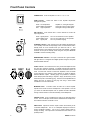
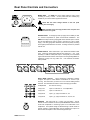
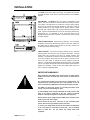
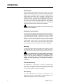
GR8A
8 Channel Amplifier
USER GUIDE
Publication AP4298
Limited One Year Warranty
This product has been manufactured in the UK by ALLEN & HEATH and is
warranted to be free from defects in materials or workmanship for a period of one
year from the date of purchase by the original owner.
To ensure a high level of performance and reliability for which this equipment has
been designed and manufactured, read this User Guide before operating.
In the event of a failure, notify and return the defective unit to ALLEN & HEATH or
its authorised agent as soon as possible for repair under warranty subject to the
following conditions
Conditions Of Warranty
The equipment has been installed and operated in accordance with the
instructions in this User Guide
The equipment has not been subject to misuse either intended or accidental,
neglect, or alteration other than as described in the User Guide or Service
Manual, or approved by ALLEN & HEATH.
Any necessary adjustment, alteration or repair has been carried out by ALLEN &
HEATH or its authorised agent.
The defective unit is to be returned carriage prepaid to ALLEN & HEATH or its
authorised agent with proof of purchase.
Units returned should be packed to avoid transit damage.
In certain territories the terms may vary. Check with your ALLEN & HEATH agent
for any additional warranty which may apply.
This product complies with the European Electromagnetic
Compatibility directives 89/336/EEC & 92/31/EEC and the European
Low Voltage Directives 73/23/EEC & 93/68/EEC.
Any changes or modifications to the equipment not approved by Allen & Heath
could void the compliance of the equipment and therefore the users authority to
operate it.
GR8A User Guide AP4298 Issue 2.
Copyright © 2001 Allen & Heath Limited. All rights reserved
Manufactured in the United Kingdom by
Allen & Heath Limited
Kernick Industrial Estate, Penryn, Cornwall, TR10 9LU, UK
http://www.allen-heath.com
2
GR8A USER GUIDE
CONTENTS
Warranty............................................................................... 2
Safety Warnings................................................................... 3
Welcome to the Allen & Heath GR8A .................................. 4
General Precautions ............................................................ 4
Specifications ....................................................................... 5
Front Panel Controls ............................................................ 6
Rear Panel Controls and Connectors .................................. 7
Installation ............................................................................ 9
Operation ........................................................................... 10
Block Diagram.................................................................... 11
SAFETY WARNING!
Mains electricity is dangerous and can kill. Mains
voltage is present within the GR8A.
Do not remove the top cover. There are no user
serviceable parts inside the unit. Refer servicing
to qualified service personnel only.
To avoid the risk of fire, replace the mains fuse
only with the correct value and type as indicated
on the rear panel.
WARNING TO THE USER, INSTALLATION ENGINEER
Allen & Heath warns that any unauthorised changes or modifications
to the GR8A unit may invalidate the legal compliance of the unit and
could void the user’s authority to operate the equipment.
DO NOT REMOVE THE MAINS EARTH CONNECTION
To ensure your safety the mains earth is connected to the chassis
through the power lead. Do not remove this connection.
GR8A USER GUIDE
3
Welcome to the Allen & Heath GR8A
The GR8A is one of a range of architectural sound products in the Allen & Heath Contractor Series. It
is an 8 channel audio power amplifier designed to work with multi-output zoning mixers such as the
Allen & Heath GR05, GR1, DR128 and DR66. Modern amplifier technology has enabled the GR8A to
achieve multi-channel high power output in a relatively small case size. Much time and effort has been
invested into making the GR8A an excellent performing, reliable and cost effective solution wherever
multi-channel audio is required. The GR8X transformer rack option is available from Allen & Heath to
enable the amplifier to drive 70V or 100V loudspeaker systems.
This user guide presents a quick reference to the function and application of the GR8A. We
recommend that you read this guide fully before starting. Whilst we believe the information presented to
be reliable, we do not assume responsibility for inaccuracies. We also reserve the right to make
changes in the interest of further product development.
Main Features
•
8 Independent audio power amplifiers in a 2U chassis with removable rack ears
•
60W per channel into 4 ohms, 40W into 8 ohms
•
Outputs bridgeable for 120W into 8 ohms
•
Balanced XLR inputs with common mono/stereo source switching in groups of four
•
Speaker outputs on Phoenix type removable screw terminal connectors
•
3 Colour input signal metering
•
Selectable output monitoring on headphones or local speaker
•
Full output protection and 3 speed fan cooled temperature management system
•
Battery power backup facility
•
Remote output ‘standby’ control per channel
Service And Technical Support
Under normal operating conditions the GR8A does not require user maintenance or calibration apart
from occasional vacuuming of the air intake filter should it become ingrained with dust.
To avoid damage to internal components by mishandling and/or misconnection, service
work should be referred only to technically competent personnel.
We are able to offer further product support through our world-wide network of approved dealers and
service agents. You can also access our Web site on the internet for information on our product range,
assistance with your technical queries or simply to chat about audio matters. To help us provide the
most efficient service please keep a record of the serial number, date and place of purchase to be
quoted in any communication regarding this product.
General Precautions
Your GR8A is ruggedly constructed to give many years of reliable operation. However, you will extend
the life of the amplifier and preserve its cosmetics by applying these simple common sense
precautions:
Avoid storing or using the amplifier in conditions of excessive heat or cold, or in positions where it is
likely to be subject to vibration, dust, smoke, dirt or moisture. Do not use any liquids to clean the
control surface of the unit. Use a soft dry brush or dry lint-free cloth. Check the air intake dust filter
regularly and vacuum from the outside to remove dust build up as necessary. Avoid using the amplifier
close to strong sources of electromagnetic radiation such as video monitors, mains and high power
electric cabling.
Do not remove the service cover. There are no user serviceable parts inside. All the controls and
installation settings for the unit are accessible from the outside.
4
GR8A USER GUIDE
Specifications
Connections
Input x8............................................ Balanced XLR pin 2 hot
Speaker x8 ......2 pin Phoenix type pluggable screw terminal
Headphones ........................................ TRS tip left, ring right
Monitor........ Unbalanced TRS tip signal, ring, sleeve ground
Remote standby ........................................ 9 pin D connector
Battery backup......................... 4 pin Phoenix type pluggable
AC mains input ....................................................... 3 pin IEC
Input source selection
Independent........................................One input per channel
Common mono .................................Input1 to 1-4 and/or 5-8
Common stereo ................ Input1/2 to 1/2,3/4 and/or 5/6, 7/8
Input sensitivity for max power ...............................+4dBu
Protection
Outputs..................................Short circuit, thermal, overload
Power up ........................................... 2 second auto standby
Temperature.......... Sensing fan – stop, medium, high speed
Temperature indicator.............. 3 colour – green, amber, red
AC power requirement
Moulded plug to IEC lead supplied (country dependent)
Internally wired for country... 100, 110, 120, 220 or 240V.AC
Operating frequency ............................................... 47-63 Hz
Quiescent ................................................................ 50 Watts
Maximum............................................................... 500 Watts
Mains fuse................................................T6.3A 250V 20mm
Battery backup requirement
24V battery x2 ......................................................... 10A max
Input impedance ................................................> 20k ohms
Input signal meters........................3 colour led per channel
Source ........................................................Post level control
Green..................................................... 140mW into 4 ohms
Amber ......................................................... 10W into 4 ohms
Red .......................................................Approaching clipping
RMS output power per channel
Unbridged ............................................ 60 Watts into 4 ohms
Unbridged ............................................ 40 Watts into 8 ohms
Bridged .............................................. 120 Watts into 8 ohms
Peak transient power
Unbridged ................................................. 130W into 4 ohms
Bridged ..................................................... 250W into 8 ohms
Slew rate................................................................... 10V/uS
Frequency response ................... 20Hz to 20kHz +0/-0.5dB
Total Harmonic Distortion
6W into 8 ohms @ 1kHz.............................................. 0.03%
Signal to noise ratio
Relative to 60W into 4 ohms ......................................-100dB
Stand by ................................. Separate control per channel
Control ......................... Switch common +15V to channel pin
Attenuation ...................................................................-80dB
Dimensions
19” rack mount ....................................... 482 x 380 x 88 (2U)
Desk mount .................................................... 440 x 380 x 92
Inter-channel Crosstalk............relative to 60W into 4 ohms
@ 1kHz......................................................................< -70dB
@ 10kHz....................................................................< -60dB
Weight
Unpacked ...........................................................12kg (26lbs)
Packed ..................................................................13kg (29lb
GR8A USER GUIDE
5
Front Panel Controls
POWER switch Turns the amplifier on or off. I = on, 0 = off.
TEMP indicator
Shows the status of the amplifier temperature
management system:
Green Low temperature
Amber Medium temperature
Red
High temperature
Amplifier on, cooling fan stopped
Cooling fan running at slow speed
Cooling fan running at fast speed
SIG indicators Each channel has a 3-colour indicator to monitor the
output signal level:
Green Signal present
Amber Medium level
Red
Signal peak
Turns on at 140mW into a 4 ohm speaker.
Turns on at 10 watts into a 4 ohm speaker.
Turns on just before clipping
STANDBY indicators Each channel has a red indicator that lights when
it is in standby mode with its output stage muted. All channels are held in
standby mode for a few seconds when you switch the unit on. This
prevents thumps in the speakers while the power rails stabilise. Selected
channels can be put into standby mode using the rear panel REMOTE
STANDBY connector switching facility.
BRIDGE MODE indicators Each pair of channels has a green indicator
that lights when it is configured for bridged operation using the rear panel
OUTPUT MODE switches.
LEVEL controls Each channel has a rotary control that adjusts its level
from fully off to maximum sensitivity. In bridged mode the odd numbered
channel control sets the overall level and the even numbered control is not
used. Use the level controls to match the amplifiers to the connected
source equipment, set maximum volume allowed, or adjust the balance
between different outputs. Blanking plugs are provided for situations
where tamper-proof level setting is required. Simply set the level, pull off
the knob and push in the blanking plug. The level can be adjusted without
refitting the knob by pulling out the plug and using a small slotted
screwdriver to turn the control shaft.
MONITOR switch
8 Position switch to select one of the 8 amplifier
outputs as the monitor source for headphones or local speaker. This lets
you check the selected amplifier from its speaker terminals attenuated
through a series resistor to match the sensitivity of the headphones.
PHONES socket Plug in headphones to listen to the selected monitor
source. This is a TRS jack socket wired for standard stereo headphones.
The selected channel is monitored in mono.
SENS switch Adjusts the monitor output to match the sensitivity of the
connected headphones. This is an underpanel tamperproof switch to
prevent accidental operation. Use a pen or similar pointed object to
change its setting. The output level is increased when the switch is in its
pressed position.
6
GR8A USER GUIDE
Rear Panel Controls and Connectors
MAINS INPUT
The GR8A AC mains voltage setting is factory wired
according to country of order. An IEC power lead with moulded plug
suitable for your mains outlet is supplied with the unit.
Check that the mains voltage marked on the rear panel
matches your local supply.
Read and heed all the warnings printed on the rear panel and
at the start of this user guide.
BATTERY INPUT An emergency back-up supply such as battery or UPS
is a common requirement for public announcement installations. The
GR8A has a 4way Phoenix type pluggable screw terminal input to connect
two 24V DC batteries for back-up power in the event of a loss of mains
supply. Use heavy gauge wire and observe the correct polarity according
to the legend printed above the connector. A mating connector is provided
with the unit.
SIGNAL INPUTS Each channel has a 3-pin female XLR chassis socket
input. These are electronically balanced and wired pin 2 = hot. Input
sensitivity is +4dBu for rated power output. Good quality 2 core screened
signal cable should be used for these inputs to avoid signal degradation or
interference pickup over long cable runs. Use balanced connections
where possible.
INPUT MODE switches
Three tamperproof underpanel switches
configure the inputs to allow different combinations of common input
sourcing. Use these when you have one or two sources feeding several
channels. This eliminates the need for custom multi-plug input cables.
8 Independent
No common sourcing
4 way mono
Input 1 to channels 1–4. 5-8 independent
8 way mono
Input 1 to channels 1–8
2 way stereo
Input 1 (L), 2 (R) to channels 1/2, 3/4
4 way stereo
Input 1 (L), 2 (R) to channels 1/2, 3/4, 5/6, 7/8
MONITOR
TRS output with tip = signal, ring and sleeve = ground.
Follows the source selected on the front panel MONITOR switch to feed a
small local loudspeaker or monitoring system as an alternative to the
headphones. The speaker voltage is reduced through a series resistor to
prevent overload. Further attenuation may be needed if this output is to
feed an external amplifier or other line level equipment input.
GR8A USER GUIDE
7
REMOTE STANDBY 9-pin D-type female connector can be wired to
external switches to remotely mute individual channels. Any combination
of channels can be muted at the same time. Putting a channel into
standby mutes its output driver stage. To mute a channel simply switch its
connector pin to the common (+15V) pin. Do not connect the common pin
to any other equipment. The front panel STANDBY indicator lights to warn
that the channel is muted. Use shielded cable for long cable runs.
SIGNAL OUTPUTS These are the amplifier outputs that connect to the
speaker terminals. Each has a 2-way Phoenix type pluggable screw
terminal connector. Mating plugs are provided with the unit. Use suitable
gauge speaker wire, ensure reliable connections and observe the correct
polarity according to the legend printed above the connector. The
following connections are typical.
NORMAL
70V or 100V TRANSFORMER OPTION
BRIDGED
OUTPUT MODE switches The GR8A amplifier outputs can operate nonbridged (independently) or be bridged in pairs according to the setting of
the tamperproof underpanel mode switches. Press the switch to select
bridge mode using a pen or similar pointed object. This configures two
amplifiers to work together into one speaker. Use bridge mode when you
need a lot more amplifier power to drive a single speaker.
BRIDGE MODE Use the odd numbered channel input and controls. The
even numbered input is disabled. You should blank off the unused level
controls using the plugs provided. The front panel BRIDGE indicator lights
to show the pair of channels is bridged. If you are using remote standby
switching for the bridged pair make sure you switch them both together.
TRANSFORMER OPTION The high quality GR8X transformer option is
available separately from Allen & Heath to convert the amplifier outputs to
drive 70V or 100V speaker lines. Alternatively, any standard 70V or 100V
line transformer of suitable power rating and quality to match the amplifier
may be used.
To avoid damage to the amplifier make sure you do not
connect a combined speaker impedance of less than 4 ohms in
single mode, or less than 8 ohms in bridge mode.
To avoid damage to the speakers do not drive the amplifier
into clipping or feed it with a previously clipped signal.
Do not use bridge mode when using the amplifier with a 70V
or 100V line transformer.
8
GR8A USER GUIDE
INSTALLATION
The GR8A can be rack or desk top mounted. It is supplied with rack ears
and desk feet fitted. These may be removed according to the installation
required.
RACK MOUNT The GR8A fits into a 2U space in a standard 19” rack
system. The rack should allow a minimum side to side opening of 445mm
and a depth of at least 420mm to include the connector space required.
Secure the unit into the rack using two M6 bolts on each side. These are
usually provided by the rack supplier and are typically chrome or black
bolts that seat in black plastic cups to prevent scratching the equipment
panel. If space is tight beneath the unit you can remove the plastic feet by
prizing them off. It is advisable to mount the heavier units such as
amplifiers towards the bottom of the rack. This lowers the centre of gravity
for easier handling.
DESK OR SHELF MOUNT Remove the two rack ears. Use a crosspoint
screwdriver to remove the two M4 fixing screws on each side. Make sure
the plastic feet are fitted as these protect the mounting surface from
scratching and prevent the unit sliding.
CABLE ROUTING It is well known that the majority of hum, noise and
routing problems are caused by poor connections and cables. Use high
quality cable and connectors and check for reliable soldering and
assembly. Use balanced connections and screened cables for the inputs.
If you have problems with ground loops lift the screen connection at one
end of the input cables or operate the source equipment ground lift
switches. Use adequately rated speaker wire for the outputs. Input cables
may be run together but outputs should be separated to avoid interaction
between the amplifiers. Route all input and output cables away from
mains, computer and lighting cables.
IMPORTANT WARNINGS !
When positioning the GR8A ensure that the front air intake and the
exhaust vent on the left hand side of the unit are not obstructed or
blocked.
It is normal for the amplifier to run hot when it is working hard. It is
important that air flow around the unit is not restricted. If free air
flow is restricted then additional forced cooling should be provided.
The GR8A is a heavy item. Ensure it is securely fixed where it will
not fall or slip and cause damage or injury.
To avoid damage to the internal assemblies do not fit screws or drill
holes in the sides or underside of the unit. Secure to external
brackets or fittings through the front panel rack mounting holes.
Ensure that the mains voltage setting marked on the rear panel is the
same as your local mains supply.
Do not remove the top cover. There are no user serviceable parts
inside. Refer servicing to qualified service personnel.
To ensure your safety make sure that all the chassis and metalwork
in the rack system is connected to mains earth. Use a continuity
meter to check this. Do not remove any safety earths from
equipment.
GR8A USER GUIDE
9
OPERATION
Switching On
Connect all input and output cables to the unit, ensure it is correctly
installed as described previously and that the input and bridge mode
switches are set as required. Make sure the mains voltage setting is
correct and the mains switch in the ‘0’ off position. Start with all level
controls set minimum. Ensure that all equipment connected to the
amplifier is turned on. Switch the unit on by pressing the mains switch to
its ‘I’ position. The TEMP indicator lights, changing from amber to green
after a few seconds. The fan runs briefly during this time. The STANDBY
indicators illuminate for a few seconds and then go out. This shows that
the outputs are muted while the unit powers up and stabilises.
To avoid loud thumps or damage to your speakers always turn
amplifiers on last and off first.
Setting the Level Controls
It is typical to set the amplifier level controls to maximum and adjust the
volume using the preceding mixer or other equipment controls. This is fine
if the equipment gain structure is correctly set and the preceding
equipment operating level matches the sensitivity of the amplifier. If this is
not the case you can use the amplifier level controls to correct the signal
matching. These controls can also be used to preset the maximum
volume allowed for each output, or to balance the volume between
different outputs. Remove the knobs and fit the blanking plugs provided
with the unit if you wish to lock the controls and make them tamperproof.
Metering
A 3-colour signal meter indicator is provided for each channel to monitor
the output signal level. This is off when there is no signal, green for low
levels, amber for normal levels and red as the signal approaches clipping.
It is very important not to operate the amplifier with the meter
led showing red for more than a brief instant, for example on music
peaks, as this may result in damage to the loudspeaker as the
amplifier clips the music signal. It is also important not to send the
amplifier an already clipped signal as this may also damage the
loudspeaker.
Channel Monitoring
Use headphones or a small speaker to monitor the amplifier output
signals. Select the channel you wish to listen to using the front panel
rotary switch. The signal is sourced from the speaker terminals so that
you can check the signal as it is routed to the speaker.
Fan Cooling
It is normal for the amplifier to run hot when it is working hard. The fan
switches from off to slow to fast depending on internal temperature. The
TEMP indicator lights green, amber or red accordingly.
10
GR8A USER GUIDE
BLOCK DIAGRAM
GR8A USER GUIDE
11