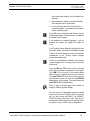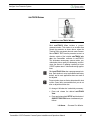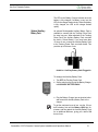
1
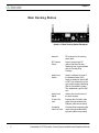
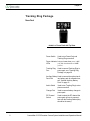
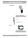
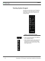
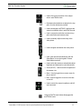
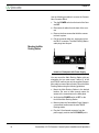
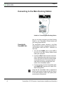
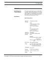
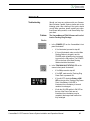
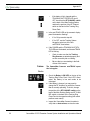
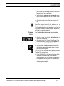
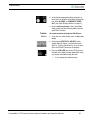
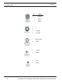
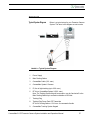
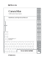
CameraMan
3ccd Presenter Camera System
Installation and Operations Manual
071838700 rev. C
JUNE 2005
Contacting Grass Valley
Region
Voice
Fax
Address
Web Site
North America
(800) 547-8949
Support: 530-4784148
Sales: (530) 478-3347
Support: (530) 4783181
www.thomsongrassvalley.com
Pacific Operations
+852-2585-6688
Support: 852-25856579
+852-2802-2996
Grass Valley
P.O. Box 599000
Nevada City, CA
95959-7900 USA
U.K., Asia, Middle East +44 1753 218 777
France
+33 1 45 29 73 00
Germany, Europe
+49 6150 104 782
+44 1753 218 757
+49 6150 104 223
Copyright © Thomson Broadcast and Media Solutions All
rights reserved.
Grass Valley Web Site
The www.thomsongrassvalley.com web site offers the following:
Online User Documentation — Current versions of product cat-
alogs, brochures, data sheets, ordering guides, planning
guides, manuals, and release notes in .pdf format can be
downloaded.
FAQ Database — Solutions to problems and troubleshooting
efforts can be found by searching our Frequently Asked
Questions (FAQ) database.
Software Downloads — Software updates, drivers, and patches
can be downloaded.
CameraMan 3ccd Presenter Camera System Installation and Operations Manual
Table of Contents
List of Figures x
Meet Your Presenter System
1
Presenter System Components 3
Main Docking Station 6
Tracking Ring Package 8
Tracking System Keypad 10
Connect Your Presenter System
13
Installing the Camera System 13
Connecting to the Main Docking Station 16
Tracking Ring Power Pack Assembly 18
Configure Your Presenter
System 21
Configuring the Main Docking Station 21
Configuring the Tracking System Keypad 22
Other Configurations 26
071838600
June 2005
viii
Use Your Presenter System
29
System Start Up 29
Using autoTRACK 32
Using AutoTRACK Views 34
Using Subject Position and Pan/Tilt Arrows 38
Using AutoFIND and Tracking Freeze 40
Using Location Presets 41
Controlling the Zoom, Focus and IMAGE 43
Controlling the Camera Setup Mode 44
Appendix A
Specifications and Clearance Diagram 47
Appendix B
Troubleshooting 49
Appendix C
Pinout Connections 55
Appendix D
Typical System Diagram 57
Appendix E
Glossary of Terms 59
Appendix F
Warranty Information 61
Index 63
ix
CameraMan 3-CCD Presenter Camera System Installation and Operations Manual
List of Figures
Main Docking Station 3
Tracking System Keypad 5
Main Docking Station Backpanel 6
Power Pack with Top View 8
Tracking Ring Assembly 9
Belt with Power Pack 9
Tracking System Keypad 10
Connector Block and CameraMan 13
Backpanel with Power Supply 14
Connecting Main Docking Station 16
Antenna Hanging Loosely 18
Front and Back Tracking Sensors 19
Sensor Blocked by Hair 19
360o of Coverage 20
Facing the CameraMan Camera 24
Facing with CameraMan Camera 25
Default PAN/TILT 26
AutoTRACK Window 27
Auxiliary Battery Pack Plugged In 31
(Left to Right) Tight, Wide, Left, Right AutoTRACK Views 34
Docking Station Clearance Diagram 48
Typical System Diagram 57
071838600
June 2005
x
List of Figures
xi
CameraMan 3-CCD Presenter Camera System Installation and Operations Manual
Chapter 1
Meet Your Presenter System
Congratulations On Your
Purchase
Your new Grass Valley Camera System uses proven
automatic tracking technology to help improve your
distance learning, telemedicine and videoconferencing applications. You should use this manual in conjunction with the installation and operations manual
that came with your CameraMan 3-CCD camera.
This manual covers the connection, configuration,
and usage of your new Presenter Camera System.
Along with basic pan, tilt, zoom, focus and IMAGE
control of your CameraMan camera, the Presenter
Camera System boasts advanced features and
functionality. The system comes with an input/output
Main Docking Station, the Tracking Ring Package
with built-in microphone, and the wireless RF (or
hard-wired) Tracking System Keypad from which
autoTRACK Views and other tracking functions are
controlled.
If you have questions regarding the installation or
operation of your CameraMan 3-CCD General Pan/
Tilt camera, refer to the installation and operations
manual included with the camera.
071838600
June 2005
1
Chapter 1
You’ll see three icons in this manual:
This icon alerts you to important instructions in
the operation and maintenance of your Camera
Control Keypad.
This icon alerts you to tips or noteworthy suggestions in the operation, use or maintenance of your
Camera Control Keypad.
This icon refers you to the 3-CCD Camera Installation and Operations Manual that came with your
camera.
Your 3-CCD Presenter Camera System
should include these components:
• One 3-CCD Main Docking Station
• One 10’ Main Docking Station Cable
• One Tracking Power Pack
• One Tracking Ring Sensor
• One Tracking Ring Belt
• One Power Pack Charger
• One 3-CCD Tracking System Keypad
• One 3-CCD Presenter Camera System Operations Manual
• One 3-CCD Tracking Ring Package Quick Reference Card
• One Tracking Ring Power Pack Pouch
• CameraMan Keypad Cable (6-pin phone) - 25
feet
• Two Rubber Duck Antennas
The terms Visibly Better, IMAGE, and Digital RF
900, are registered trademarks of Grass Valley, Inc.
in the United States of America. The terms CameraMan and Grass Valley are registered logos in the
United States of America. Federal law prohibits any
2
CameraMan 3-CCD Presenter Camera System Installation and Operations Manual
Meet Your Presenter System
commercial use of these registered trademarks and
logos.
The manufacturer reserves the right to change
specifications and warranty at any time without
notice or obligation.
Refer all Warranty and Servicing to the Grass Valley
Product Support listed in the back of the installation
and operations manual that came with your CameraMan camera.
No part of this manual may be copied or reproduced
without express written consent of Grass Valley, Inc.
© 1998 Grass Valley, Inc.
DURACELLÆ is a registered trademark of Duracell,
Inc.
Presenter System Components
The Presenter Camera System comes with various
pieces that, using both infrared (IR) and radio-frequency (RF) autoTRACK technology, assist the
CameraMan in automatically following you around
the room. If you have purchased this as an upgrade,
then your package will include all the necessary
components except the camera.
Main Docking Station
FIGURE 1.1 Main Docking Station
The Main Docking Station is the I/O center of your
Presenter Camera System. It comes standard with
CameraMan 3-CCD Presenter Camera System Installation and Operations Manual
3
Chapter 1
two RF frequencies (alternate channels are available for special order). After you connect it to your
CameraMan camera, you can control the camera’s
video and audio out, as well as its movement via the
tracking ring, tracking keypad, or another external
control device. The Main Docking Station consists
of:
• Main Docking Station with two antennas.
• 10’ multi-conductor cable with 37-pin D-sub connectors.
Tracking Ring Package
The Tracking Ring Package uses Grass Valley’s
patented autoTRACK technology to communicate
with your CameraMan camera. By wearing the
Tracking Ring, you can move freely throughout the
room while the camera automatically follows your
every move. This gives you the freedom to get up
from the conference room table and walk to a flipchart without depending on a human camera operator or a system with a fixed- or static-view camera.
The Tracking Ring Package consists of:
• Tracking Ring with built-in microphone
• Tracking Power Pack with a built-in 12 Hour
Rechargeable Battery
• Tracking Power Pack Belt
4
CameraMan 3-CCD Presenter Camera System Installation and Operations Manual
Meet Your Presenter System
• Tracking Power Pack Pouch
• Power Pack Charger
Tracking System Keypad
FIGURE 1.2 Tracking System Keypad
The Tracking System Keypad (7) lets you control
camera features such as autoTRACK Views, location presets and manual pan/tilt functions in either a
wireless RF, or hard-wired mode. With icons illustrating every autoTRACK View button, you can easily understand what each camera view should look
like.
Also Available
(Sold Separately)
• Auxiliary Battery Pack
CameraMan 3-CCD Presenter Camera System Installation and Operations Manual
5
Chapter 1
Main Docking Station
FIGURE 1.3 Main Docking Station Backpanel
6
Antenna
RF receivers for the tracking
power pack.
RF Channel
Select
Used to select which RF
channel the Main Docking
Station will use to communicate
with the Tracking Ring
Package.
Audio Level
Switch
Used to configure the level of
the balanced audio (XLR)
output, available for either LINE
or MIC level, depending on the
type of audio system interfacing
with the CameraMan system.
The unbalanced ouput is LINE
only.
Audio Level
Adjust
Used to fine tune the level of
the audio outputs.
S-Video Out
Jack
Provides direct S-Video video
output through standard miniDIN jack (cable not provided).
Composite
Video Out Jack
Provides direct composite video
output through standard BNCtype jack (cable not provided).
CameraMan 3-CCD Presenter Camera System Installation and Operations Manual
Meet Your Presenter System
RS-485 IN and
OUT Jacks
4-position modular handset
jacks used for RS-485
communications between the
camera system and other
CameraMan devices.
PVI COM Jack
6-conductor RJ-11 jack used for
communication with the
Tracking System Keypad in
hard-wired mode.
RS-232 Port
Standard DB-9 (female)
connector provides RS-232
communications capability for
devices like PCs or other
vendor-control systems.
Auxiliary
Provides communications to
Communications select CameraMan perpherals.
Port A
Do not use unless otherwise
specified.
Audio Balanced
Jack
Standard XLR-type connector
provides balanced line or mic
level audio output to connect to
a standard mixer or similar
audio equipment.
Audio
Unbalanced
Jack
Standard RCA-type connector
provides unbalanced, line level
only mono audio output to
connect to a standard mixer or
similar audio equipment.
Base Unit Port
37-pin D-sub connector
provides communication
between the Main Docking
Station and the Camera System
via a 10’ multi-conductor cable.
DC Power
Power input for the Main
Docking Station.
CameraMan 3-CCD Presenter Camera System Installation and Operations Manual
7
Chapter 1
Tracking Ring Package
Power Pack
FIGURE 1.4 Power Pack with Top View
Power Switch
Used to turn Power Pack and
Tracking Ring on and off.
Power Indicator Lets you know when power is ON
LEDs
(red) and when batteries are LOW
(yellow).
Tracking Ring
Port
Used to connect Tracking Ring to
power pack, see “Tracking Ring
Package” on page 29.
Auxiliary Battery Used to connect the optional auxilPack Port
iary battery pack for extended use,
see “Optional Auxiliary Battery
Pack” on page 31.
8
Audio Switch
Used to turn Tracking Ring’s microphone on and off.
Charger Port
Used to connect battery charger to
power pack.
RF Channel
Switch
Used to select the RF channel the
power pack will use to communicate with the Docking Station (they
should be the same).
CameraMan 3-CCD Presenter Camera System Installation and Operations Manual
Meet Your Presenter System
Tracking Ring Assembly
FIGURE 1.5 Tracking Ring Assembly
• Back Sensor
• Front Sensor
• Tracking Ring Port Connector
Belt Assembly
FIGURE 1.6 Belt with Power Pack
Using the pouch, clip power pack on belt as shown.
CameraMan 3-CCD Presenter Camera System Installation and Operations Manual
9
Chapter 1
Tracking System Keypad
Next, take a look at the front of your Tracking System Keypad. It is the control center for your Presenter Camera System and is composed of the
following features.
FIGURE 1.7 Tracking System Keypad
• Used to recall preset locations. The HOME button is considered PRESET 1.
• Used to change the position and perspective of
the presenter in the video frame while being
tracked by the camera (choose between Tight,
Wide, Right and Left).
10
CameraMan 3-CCD Presenter Camera System Installation and Operations
Meet Your Presenter System
• Used to fine-tune the position of the subject
while in autoTRACK mode.
• Illuminates when batteries are placed in the keypad or function buttons are pressed.
• Used to disengage autoTRACK, and freeze the
camera’s movement while in autoTRACK mode.
• Used in conjunction with other controls for keypad customization and camera setup.
• Used to manually adjust visual clarity of the
video picture.
• Used to brighten and darken the video picture.
• Used, when pressed simultaneously with the
Setup Button, to turn the keypad’s Camera
Setup Mode on and off.
• Used to allow the camera to automatically adjust
brightness and darkness for each video picture.
• Zoom (IN/OUT) - Used to control the tightness of
the camera view.
• Menu - Used to toggle the on-screen menu display on and off.
• Bars - Used to toggle the on-screen color bars
on and off.
• Used to control the camera’s up/down, and left/
right movement.
Using the Pan/Tilt arrow buttons disengages the
autoTRACK mode.
CameraMan 3-CCD Presenter Camera System Installation and Operations Manual
11
Chapter 1
This page was intentionally left blank.
12
CameraMan 3-CCD Presenter Camera System Installation and Operations
Chapter 2
Connect Your Presenter System
Installing the Camera System
Now that you’ve identified the components of your
Presenter Camera System, as well as their individual buttons, ports and jacks, you can begin connecting them to your CameraMan camera.
Removing the CameraMan Connector Block
(Upgrade Only)
FIGURE 2.1 Connector Block and CameraMan
If you are performing an initial installation of a system package, as opposed to an upgrade, this is not
necessary.
071838600
June 2005
13
Chapter 2
Use the following procedure to remove the CameraMan Connector Block:
1. Turn the POWER switch on the back of the Cam-
era OFF.
2. Disconnect all cables from the back of the cam-
era.
3. Remove the three screws that hold the connec-
tor block in place.
4. Pull the connector block out, unplugging it from
the DB-37 connector. The Main Docking Station
cable plugs into this port.
Mounting the Main
Docking Station
FIGURE 2.2 Backpanel with Power Supply
You can mount the Main Docking Station with any
orientation, but you must mount it within 10’ of the
autoTRACK camera (use only the supplied CameraMan cable to connect the two units). Mount the Main
Docking Station using the following guidelines:
1. Mount the Main Docking Station in the desired
location. Be sure to leave enough space for
access to the connections on the back panel.
2. Verify that the POWER switch is OFF on the
front of the Main Docking Station.
3. Mount or place the CameraMan Power Supply in
a convenient location near the autoTRACK
Docking station.
4. Plug the 5.5mm female connector from the
power supply cord into the DC POWER jack in
14
CameraMan 3-CCD Presenter Camera System Installation and Operations
Connect Your Presenter System
the back of the docking station. Do NOT plug it
directly into the back of the camera.
5. Plug the other end of the power supply into a
120 VAC outlet.
6. Connect the antennas to the appropriate con-
nectors and position them both to point vertically
for optimum performance.
For best performance, locate the antenna in free
space, at least 6’ from the camera or any wires,
metal surfaces, wall, etc.
Make sure the Docking Station is at least 1 foot
away from the camera unit.
See “Docking Station Clearance Diagram” on
page 48.
Multi-Camera
Applications
In a multi-camera application, refer to the multi-camera section of the General Pan/Tilt Operations
Manual. Follow the appropriate procedure, using
the RS-485 connections on the back of the Main
Docking Station instead of the connections on the
back of the camera.
CameraMan 3-CCD Presenter Camera System Installation and Operations Manual
15
Chapter 2
Connecting to the Main Docking Station
FIGURE 2.3 Connecting Main Docking Station
Now you can begin connecting your Main Docking
Station to your CameraMan Camera System and
your camera control devices.
Connecting the
CameraMan Cable
The autoTRACK camera connects to the Main
Docking Station using the supplied CameraMan 10’
multi-conductor cable with DB-37 connectors on
both ends.
1. Verify that the POWER switch is turned OFF on
the front of the Main Docking Station before
making this connection.
2. Connect the DB-37 male connector to the back
of the CameraMan camera and secure the connection using the two connector screws located
on the cable connector. This ensures that the
cable does not become dislodged due to the
motion of the CameraMan camera.
3. Connect the other end of the CameraMan cable
to the BASE UNIT connector on the back of the
Main Docking Station.
Verify that the CameraMan Cable is supported so
that the camera does not drag the cable as it moves.
If the camera drags the cable, then system performance may be compromised.
16
CameraMan 3-CCD Presenter Camera System Installation and Operations
Connect Your Presenter System
Connecting a Keypad/
Controller
The Tracking System Keypad can be hard-wired to
the Main Docking Station using a CameraMan Keypad Cable (provided separately).
1. Connect one end of the cable to the RJ-11 type
jack located in the battery compartment of the
keypad. (Remove batteries)
2. Connect the other end of the cable to the RJ-11
type jack to the back of the Main Docking Station, labeled PVI COM.
3. The LED on the keypad should illuminate
momentarily, indicating that the keypad is ready.
Using cable other than supplied cable for the PVI
COM port may cause damage. The Tracking System Keypad can be hard-wired up to a maximum
distance of 250’.
Connecting to the RS232 Port
The Presenter Camera System provides for RS-232
communications using the DB-9 jack on the back of
the Main Docking Station, labeled RS-232. this RS232 port can be used to control the CameraMan
camera from external devices, such as a PC or
other vendor control system (i.e., AMX or Crestron).
Connect to this port using a standard computer
cable with DB-9 connector. This port operates at
9600 Baud (19,200 with CameraMan SHOT Director), No Parity, and software hand-shaking using
CameraMan High Reliability or Basic protocols (only
High Reliability with SHOT Director). The LED
located above the RS-232 port indicates communication activity.
Verify which protocol is being used by checking the
PROTOCOL switch (switch bank B- switch 1) on the
back of the CameraMan camera, and which Baud
rate (9600 or 19,200) is needed by checking switch
bank A-7.
For more information on setting the PROTOCOL on
your CameraMan camera, see the Installation and
Operations Manual that came with the camera.
CameraMan 3-CCD Presenter Camera System Installation and Operations Manual
17
Chapter 2
Tracking Ring Power Pack Assembly
Now you’re ready to assemble the Tracking Ring
Package and learn how to wear it properly to ensure
that your CameraMan camera follows you around
the room.
Tracking Ring Power
Pack Assembly
Using the Power Pack Pouch, attach the Tracking
Power Pack directly to your clothing by clipping it to
your waistline or skirt, or to the Tracking Ring Power
Pack Belt.
The Tracking Power Pack must be worn so the
antenna hangs loosely, like shown below. Do not
place the Power Pack in your pocket. This interferes
with the RF signal and may affect the audio and
tracking capability.
FIGURE 2.4 Antenna Hanging Loosely
Tracking Ring Sensors
1. Identify the sensors:
Front Sensor: equipped with a built-in microphone and tracking sensor. It is identified by the
main connector to the Power Pack.
Back Sensor: equipped with the built-in tracking
sensor only.
2. Slip the Tracking Ring around your neck.
3. Clip the Tracking Ring strap closed to form a
complete circle around your neck.
4. Verify that the Front Sensor is lying flat and cen-
tered just above chest level, and the back sensor
is lying flat on the back of your collar.
5. Plug the main connector into the port on the top
of the Tracking Ring Power Pack.
18
CameraMan 3-CCD Presenter Camera System Installation and Operations
Connect Your Presenter System
The Front and Back sensors require a direct line-ofsight link with the camera. The presenter must exercise caution to ensure no clothing or hair covers
either Sensor.
FIGURE 2.5 Front and Back Tracking Sensors
About the Sensors
You should understand how the autoTRACK Tracking Sensors work to obtain the maximum performance levels. The autoTRACK mode is an
exclusive Grass Valley feature that enables the subject wearing the Tracking Ring Package to be
tracked automatically by the camera.
Since the Tracking Sensors require a direct line-ofsight link with the camera, the subject must exercise
caution to ensure no clothing or hair covers the Sensors. This ensures constant communication with the
CameraMan camera.
FIGURE 2.6 Sensor Blocked by Hair
CameraMan 3-CCD Presenter Camera System Installation and Operations Manual
19
Chapter 2
The Front Sensor should be lying flat and centered
on the body, just above the chest level. This Back
Sensor should lie flat against the back of the collar
or neck. When a presenter turns around to point to a
flipchart, for example, the Back Sensor continues to
receive the infrared tracking signal from the camera.
FIGURE 2.7 360o of Coverage
With the proper positioning of the sensors, the CameraMan camera provides 360o of coverage for the
presenter wearing the Tracking Ring.
20
CameraMan 3-CCD Presenter Camera System Installation and Operations
Chapter 3
Configure Your Presenter System
Configuring the Main Docking Station
Before you can begin to use your new Presenter
Camera System, you need to configure its components.
There are two settings on the back of the Main
Docking Station which must be set as follows:
1. Set the RF CHANNEL switch to the desired
channel. This must match the setting on the
Tracking Ring Power Pack. If you experience
any problems on one of the channels, switch
both to the alternate channel. (Factory Default:
UP position/one dot)
2. Set the AUDIO LEVEL switch to the desired
audio output.
071838600
June 2005
•
To have a mic-level audio signal, set this
switch to MIC.
•
To have a line-level audio output, set this
switch to LINE.
21
Chapter 3
•
This switch setting will apply to the
balanced audio output only. (Factory
Default: MIC)
3. Set the AUDIO LEVEL ADJUST to the desired
volume level.
Refer to Appendix A for specifications on the audio
outputs.
Powering Up
Before you can configure the rest of you Presenter
Camera System, you need to turn the system power
ON.
Switch ON the POWER button on the front of the
Main Docking Station. The CameraMan camera
should automatically enter its position calibration
mode and then stop at the 0o Pan/0o Tilt position.
Verify that the base is now facing in the direction you
pointed the FRONT label when mounting.
For more information on mounting the CameraMan,
see the Installation and Operations Manual that
came with the camera.
Configuring the Tracking System Keypad
Tracking System Keypad
Check the KEYPAD ADDRESS rotary switch
(located in the battery compartment of the keypad)
and verify that the selected setting corresponds to
the setting of the BASE UNIT ADDRESS switch on
the back of the autoTRACK camera. If the two are
different, adjust them so that they correspond.
For more information on configuring the BASE UNIT
ADDRESS on the camera and keypad, refer to the
CameraMan Camera Installation and Operations
Manual that came with the camera.
If the Tracking System Keypad is being used in the
wireless RF mode:
1. Install the supplied AA batteries in the Tracking
System Keypad by removing the battery door
22
CameraMan 3-CCD Presenter Camera System Installation and Operations
Configure Your Presenter System
and inserting the batteries into the battery compartment.
2. After installing the batteries, replace the battery
door and press one of the pan keys.
3. Look to verify that the LED on the front of the
keypad illuminates. This indicates that the batteries are installed properly.
If the LED does not illuminate, the batteries may be
installed backwards. Reverse the way the batteries
are inserted, and try again.
If the batteries are inserted improperly, it will not
damage the keypad, the keypad will simply not
work.
If the Tracking System Keypad is being used in the
hard-wired mode, connect the CameraMan Keypad
Cable to the RJ-11 type jack located in the battery
compartment of the Tracking System Keypad.
Remove the batteries first.
You do not need batteries installed in the Tracking
System Keypad when it is being used in the hardwired mode.
Press the PAN and TILT arrows one at a time and
verify that the camera is responding to the keypad.
The COM LED on the front of the camera should
flash with every command received by the camera.
If the autoTRACK LED on the front of the camera is
not illuminated, press one of the four autoTRACK
View buttons on the keypad. This should cause the
autoTRACK LED to begin flashing.
Refer to page 32 through page 43 for details on
using the Tracking System Keypad.
You can control the CameraMan camera’s panning
motion with either the PAN/TILT arrows on the bottom, or, when using autoTRACK, the SUBJECT
POSITION arrows on the top of your Tracking System Keypad. Understanding how the camera moves
will help you stay in control of your presentations.
CameraMan 3-CCD Presenter Camera System Installation and Operations Manual
23
Chapter 3
Modification of the following features is not required
for system operation, but they are available if
needed.
For information on configuring your CameraMan
camera, refer to the Installation and Operations
Manual that came with the camera.
Understanding the
Panning Motion
The PAN/TILT and SUBJECT POSITION arrows on
your Tracking System Keypad are designed to help
you maneuver the camera both in and out of
autoTRACK mode.
FIGURE 3.1 Facing the CameraMan Camera
The default setting, shown above, is designed to
operate as if you are facing the CameraMan camera. Some examples of applications that would benefit from the default settings are:
• Distance Learning where you are the instructor.
• Presentations where you are the presenter and
the audience members are watching you on a
monitor.
• Videoconferences where you are an on-screen
participant.
• Any other application where you, the keypad
controller, need to be on camera.
24
CameraMan 3-CCD Presenter Camera System Installation and Operations
Configure Your Presenter System
FIGURE 3.2 Facing with CameraMan Camera
However, there are applications in which you do not
need to face the camera, so the default setting will
not work. In these cases, you can stand BEHIND the
camera, as shown above. But when you want the
camera to move right, the picture moves left. These
applications require that you re-orient the PAN
arrows. Some examples of applicaions that might
benefit from this re-orientation are:
• Presentations where you are not the presenter,
but are controlling the camera’s movement.
• Videoconferences where you are a moderator,
but not an on-screen participant.
• Applications where you are in a control room
controlling the camera.
• Any other application where the keypad controller does not need to be on camera.
Re-Orienting the Pan
Arrows
To re-orient (reverse) the default setting of the PAN
arrows on your Camera Control Keypad, use the following procedure:
Press and hold the TRACKING FREEZE and
SETUP buttons simultaneously. The keypad will
beep after about two seconds. Release the buttons.
This will also reverse the operation of the SUBJECT
POSITION arrows.
CameraMan 3-CCD Presenter Camera System Installation and Operations Manual
25
Chapter 3
Other Configurations
The following configurations, like the panning orientation, would apply to your specific application need.
Before changing the autoTRACK Window size, you
will need to power up the tracking ring package. See
“Tracking Ring Package” on page 29.
FIGURE 3.3 Default PAN/TILT
Maximum Pan/Tilt Travel
Once the CameraMan camera is installed, you can
configure the maximum PAN/TILT settings to the
application. The camera has a maximum PAN range
of 359o, but comes programmed with factory default
settings of ± 90o of PAN and ± 25o of TILT, as shown
above. If desired, use the following procedure to
change the maximum position settings:
1. Press and hold SETUP.
2. Press and hold one of the PAN/TILT arrows until
achieving the desired maximum position.
3. Release SETUP.
4. Listen for two beeps to indicate that the maxi-
mum position for that direction has been set.
26
CameraMan 3-CCD Presenter Camera System Installation and Operations
Configure Your Presenter System
AutoTRACK Windows
FIGURE 3.4 AutoTRACK Window
Each autoTRACK View includes a pre-programmed window. This window is an invisible area
around the presenter, as shown above, where the
Tracking Ring’s movement does not cause CameraMan to PAN or TILT. Once the presenter moves in a
direction outside of the invisible autoTRACK window, the CameraMan continues to autoTRACK.
This eliminates unnecessary camera motion, provides better picture quality for videotaping, and minimizes the amount of updating necessary at lower
CODEC update rates in videoconferencing applications.
Each autoTRACK View has a preprogrammed window. Each window is set at a predetermined factory
default, and in most applications does not need to
be adjusted.
Proper window sizes are factory-determined for best
results. Grass Valley recommends that you do not
alter or adjust the window size.
If a change in Window size is absolutely necessary:
1. Press and release the desired autoTRACK
View.
2. Press and release both SETUP and the desired
SUBJECT POSITION arrow simultaneously as
follows:
Left Arrow
CameraMan 3-CCD Presenter Camera System Installation and Operations Manual
Decrease Pan Window
27
Chapter 3
Right Arrow Increase Pan Window
Down Arrow Decrease Tilt Window
Up Arrow
Increase Tilt Window
3. Press and hold the selected autoTRACK View
until you hear two beeps indicating that the new
window size has been set.
28
CameraMan 3-CCD Presenter Camera System Installation and Operations
Chapter 4
Use Your Presenter System
System Start Up
Once all necessary connections and configurations
are made, you are ready to start up the rest of the
system.
Tracking Ring Package
1. Power ON the CameraMan camera with the
POWER switch on the Main Docking Station.
2. Set the Tracking Ring Power Pack’s Power
switch, located on the top of the unit, to ON. The
Power ON LED on the Power Pack will illuminate.
If the Power ON LED on the top of the Tracking
Ring Power Pack does not illuminate, refer to the
Troubleshooting section of this manual.
3. Verify that the TRACKING UNIT STATUS LED
on the camera’s display panel is illuminated,
indicating the communication link between the
camera and the Tracking Ring.
071838600
June 2005
29
Chapter 4
4. Press one of the four autoTRACK View buttons
on the keypad to activate the autoTRACK functionality of the Camera System (the camera will
not track until one of the autoTRACK buttons is
pressed). Once you are in autoTRACK mode,
the autoTRACK LED on the camera’s display
panel will illuminate.
If the autoTRACK LED on the CameraMan’s display panel is blinking, CameraMan is in autoTRACK
mode, but the link between CameraMan and the
Tracking Ring is not active.
To establish this link, move into the CameraMan’s
field-of-view (see the autoTRACK MODE or Troubleshooting sections of this manual for further assistance).
Rechargeable Battery
The Tracking Ring Power Pack comes with a built-in
12-hour Rechargeable Battery. When the battery is
running low, the Battery LOW LED on the top of the
Tracking Ring Power Pack illuminates. At this time
the Tracking Power Pack should be recharged or an
Auxiliary Battery Pack should be attached to the
Tracking Ring Power Pack.
To recharge the battery:
1. Turn OFF the Tracking Ring Power Pack.
2. Set the switch on the front of the Battery Charger
to TRACKING POWER PACK.
3. Plug the Battery Charger into an electrical outlet
and connect it to the Power Pack.
The Battery Charger takes two to three hours to
recharge the Tracking Ring Power Pack.
30
CameraMan 3-CCD Presenter Camera System Installation and Operations
Use Your Presenter System
The LED on the Battery Charger indicates when the
battery is fully charged. If a battery is very low, the
LED on the charger flashes slowly. When the battery
is fully charged, the LED on the charger flashes
quickly.
Optional Auxiliary
Battery Pack
An optional Rechargeable Auxiliary Battery Pack is
available to connect with the Tracking Power Pack
for extra long use. When attached to the Tracking
Power Pack, the Auxiliary Battery Pack overrides
the built-in 12-hour Battery. If you need more than
12 hours of use, connect the Auxiliary Battery Pack
to the Tracking Power Pack, as shown below. This
provides up to 24 hours of use.
FIGURE 4.1 Auxiliary Battery Pack Plugged In
To recharge the Auxiliary Battery Pack:
1. Turn OFF the Tracking Power Pack.
2. Set the switch on the front of the Battery Charger
to AUXILIARY BATTERY PACK.
3. Plug the Battery Charger into an electrical outlet
and connect the Auxiliary Battery Pack to the
charger.
To get the maximum hours of use, use the 12-hour
built-in battery first until the Battery LOW light illuminates, and then attach the Auxiliary Battery Pack
for an additional 24 hours, giving you a total of 36
hours of use.
CameraMan 3-CCD Presenter Camera System Installation and Operations Manual
31
Chapter 4
The Battery Charger takes 4 to 6 hours to recharge
the Auxiliary Battery Pack.
Audio Switch
To activate Audio:
1. Set the AUDIO switch on the top of the Tracking
Ring Power Pack to ON.
2. Speak at a normal level.
If you decide not to use the Audio feature of the
Tracking Ring Package, the AUDIO switch on the
top of the Tracking Power Pack should be set to
OFF.
Using autoTRACK
Your Presenter Camera System’s ability to follow a
presenter around the room is unmatched in the
industry. Now that you’ve connected, configured,
and powered up all the system components, you
can begin to put them to use.
AutoTRACK Mode
AutoTRACK mode enables the CameraMan camera
to follow a presenter who is wearing the Tracking
Ring Package. To engage the autoTRACK mode,
press one of the four autoTRACK View buttons on
the Tracking System Keypad.
If you are using a Deluxe Camera System with Personal Locator Keypads, use the following procedure:
1. When you are ready to begin autoTRACKing,
press LOCK on the Chairperson Locator Keypad
to disable all Personal Locators from controlling
the camera.
32
CameraMan 3-CCD Presenter Camera System Installation and Operations
Use Your Presenter System
2. Press one of the four autoTRACK View buttons
on the Tracking System Keypad.
3. when you are finished autoTRACKing, press
UNLOCK on the Chairperson Locator Keypad.
For more information on the Personal Locator Keypads, see the CameraMan Personal Locator System Operations Manual.
If the LOCK button is not used and a MY TURN button is pressed while autoTRACKing, then the system disengages the autoTRACK mode and goes to
the MY TURN position.
The autoTRACK mode’s operation requires the subject to be in the field-of-view of the autoTRACK
camera.
Once the subject enters the field-of-view, the camera moves to lock onto line-of-sight tracking.
If the subject becomes obscured from its line-ofsight, then the camera stops tracking and returns to
the HOME position ( “Home (Preset 1)” on page 41).
However, momentary breaks (e.g., someone walking through the line-of-sight) has minimal effects to
the tracking performance.
CameraMan 3-CCD Presenter Camera System Installation and Operations Manual
33
Chapter 4
Using AutoTRACK Views
One of the keys to your Presenter Camera System
is its ability to not only track you around the room,
but memorize various views and presets. These
help you to make more effective and dynamic presentations.
AutoTRACK Views
Overview
You can choose from four autoTRACK Views to
engage the autoTRACK mode. These Views can be
stored and recalled from the Tracking System Keypad by pressing one of the autoTRACK View buttons.
For example, when you make a presentation, you
can change from a close head shot with the TIGHT
autoTRACK View button, to emphasize facial
expressions, to a full body shot by pressing the
WIDE autoTRACK View button. Presenters can
also share the video screen with a flipchart or other
key presentation areas with the LEFT or RIGHT
autoTRACK View buttons.
FIGURE 4.2 (Left to Right) Tight, Wide, Left,
Right AutoTRACK Views
Each autoTRACK View stores and recalls a ZOOM
perspective with an IMAGE and focus setting.
34
CameraMan 3-CCD Presenter Camera System Installation and Operations
Use Your Presenter System
Changes in the Subject Position within the video
frame also can be stored. These functions enable
the subject to fine-tune their position in each of the
autoTRACK Views.
For example, you may want to Zoom in slightly
closer on the WIDE autoTRACK View or adjust
your position in the video frame more to the left or
right. This provides you with the flexibility to customize each autoTRACK View to suit your needs.
The autoTRACK Views can be reset to accommodate these changes using the following procedures.
TIGHT AutoTRACK View
Press the TIGHT autoTRACK View button. The
video frame should show a close head shot of you.
This view is used to emphasize facial expressions. If
you would like to alter your image in this view, you
will need to reset the Tight View.
To SET or CHANGE the tight autoTRACK View:
1. After pressing TIGHT View, use the SUBJECT
POSITION arrows to position yourself in the middle of the video frame.
2. Use the manual ZOOM buttons to set the
needed Zoom perspective, if needed.
3. Use the manual FOCUS buttons to set the focal
point, if needed.
4. Use the manual IMAGE buttons to set the
needed light/dark contrast, if needed.
5. Press and hold TIGHT until you hear two beeps
indicating the new setting is stored.
To RECALL the tight autoTRACK VIEW:
Press and release TIGHT View. The camera recalls
the information stored with the TIGHT button.
CameraMan 3-CCD Presenter Camera System Installation and Operations Manual
35
Chapter 4
WIDE AutoTRACK View
Press the WIDE autoTRACK View button. The
video frame should show a wide body shot of you. If
you would like to alter your image in this view, you
will need to reset the Wide View.
To SET or CHANGE the wide autoTRACK VIEW:
1. After pressing WIDE View, use the SUBJECT
POSITION arrows to position yourself in the middle of the video frame.
2. Use the manual ZOOM buttons to set the
needed Zoom perspective, if needed.
3. Use the manual FOCUS buttons to set the focal
point, if needed.
4. Use the manual IMAGE buttons to set the
needed light/dark contrast, if needed.
5. Press and hold WIDE until you hear two beeps,
indicating the new setting is stored.
To RECALL the wide autoTRACK VIEW:
Press and release WIDE View. The camera recalls
the information stored in the WIDE button.
RIGHT AutoTRACK View
Press the RIGHT autoTRACK View button. Your
image should now be offset to the right side of the
video frame. This view is used when the presenter
wants to share the video screen with key presentation areas (a left-handed presenter may use this
view while pointing to a flipchart). If you would like to
alter your image in this view, you will need to reset
the Right View.
36
CameraMan 3-CCD Presenter Camera System Installation and Operations
Use Your Presenter System
To SET or CHANGE the right autoTRACK VIEW:
1. After pressing RIGHT View, use the SUBJECT
POSITION arrows to position yourself in the middle of the video frame.
2. Use the manual ZOOM buttons to set the
needed Zoom perspective, if needed.
3. Use the manual FOCUS buttons to set the focal
point, if needed.
4. Use the manual IMAGE buttons to set the
needed light/dark contrast, if needed.
5. Press and hold RIGHT until you hear two beeps,
indicating the new setting is stored.
To RECALL the right autoTRACK VIEW:
Press and release RIGHT View. The camera recalls
the information stored in the RIGHT button.
LEFT AutoTRACK View
Press the LEFT autoTRACK View button. Your
image should now be offset to the left side of the
video frame. This view is used when the presenter
wants to share the video screen with key presentation areas (a presenter who is right-handed may use
this view while pointing to a flip chart). If you would
like to alter your image in this view you will need to
reset the Left View.
To SET or CHANGE the left autoTRACK VIEW:
1. After pressing LEFT View, use the SUBJECT
POSITION arrows to position yourself in the middle of the video frame.
2. Use the manual ZOOM buttons to set the
needed Zoom perspective, if needed.
CameraMan 3-CCD Presenter Camera System Installation and Operations Manual
37
Chapter 4
3. Use the manual FOCUS buttons to set the focal
point, if needed.
4. Use the manual IMAGE buttons to set the
needed light/dark contrast, if needed.
5. Press and hold LEFT until you hear two beeps,
indicating the new setting is stored.
To RECALL the left autoTRACK VIEW:
Press and release LEFT View. The camera recalls
the information stored in the LEFT button.
Using Subject Position and Pan/Tilt Arrows
This section is dependent upon the orientation of
your panning arrows. We have used the default orientation for the examples.
Subject Position Arrows
In the autoTRACK mode, press any one of the four
directional Subject Position arrows to adjust your
location in the current autoTRACK View. Pressing
the up, down, right or left arrow changes the subject’s position in the video frame.
If the subject appears too low in the frame...
...press the UP arrow to lower the camera, and raise
the subject’s position.
38
CameraMan 3-CCD Presenter Camera System Installation and Operations
Use Your Presenter System
If the subject appears too far to the right in the
frame...
...press the LEFT arrow to move the subject’s position.
Manual Pan/Tilt Arrows
Press the up, down, right, or left PAN/TILT arrows to
pan or tilt the autoTRACK camera in that direction.
By pressing any of the PAN/TILT arrows in the Camera Control section of the Tracking System Keypad,
you will disengage the autoTRACK mode.
To reactivate the autoTRACK mode, press any of
the four autoTRACK View buttons. This will engage
the autoFIND mode. When the presenter is in the
field-of-view, CameraMan locks onto line-of-sight
tracking in the view selected.
CameraMan 3-CCD Presenter Camera System Installation and Operations Manual
39
Chapter 4
Using AutoFIND and Tracking Freeze
These Presenter Camera System features will help
you take control of your presentations.
AutoFIND
When you press an autoTRACK View button to
enable autoTRACK, the CameraMan will automatically begin panning toward the HOME position (
“Home (Preset 1)” on page 41), looking for the
Tracking Ring Sensor. This process is known as
autoFIND.
Once CameraMan reaches the HOME position, it
will stop if you are not in the field-of-view. Once you
enter the field-of-view...
... the camera moves to lock onto line-of-sight tracking.
If you are not in the autoTRACK mode and are out
of the field-of-view, to activate the autoFIND feature
you must press any of the four autoTRACK View
buttons. The autoTRACK LED on the CameraMan’s
display panel will then begin blinking until the camera moves to lock onto line-of-sight tracking. The
light will then stay illuminated to indicate that you are
in the camera’s line-of-sight.
Tracking Freeze
While in the autoTRACK mode, the presenter can
stop or “freeze” the camera’s movement by pressing
the TRACKING FREEZE button.
By pressing the TRACKING FREEZE button, the
autoTRACK mode will disengage.
40
CameraMan 3-CCD Presenter Camera System Installation and Operations
Use Your Presenter System
For example, you may want to use this feature when
making a presentation in front of a flipchart. You
may be offset to the right or left autoTRACK View
and be making notes on the flipchart.
Now you can press the TRACKING FREEZE button
and walk away from the flipchart while still speaking.
This enables the camera to freeze and lock on the
flipchart so that those either attending the videoconference, or viewing the videotape, can continure to
study it while you, the speaker, are no longer in the
video frame.
To reactivate the autoTRACK mode, simply press
any of the four autoTRACK View buttons. This will
engage the autoFIND mode. When you are within
field-of-view, Cameraman will lock onto line-of-sight
tracking in the view selected.
Using Location Presets
Location Presets allow you to make your presentations more effective by incorporating other media,
such as maps, flipcharts, overheads, etc. Using the
Presenter Keypad, you can store and recall a Pan/
TILT position, ZOOM perspective, FOCUS and an
IMAGE for each Location Preset.
Home (Preset 1)
The first Location Preset position is the HOME position. This is the Preset Location that you will use
most often.
For example, you may want to program the HOME
position at a podium or the conference room table,
where most of the speaking is likely to take place.
This Preset can be recalled at any time during a videoconference or videotaping session.
CameraMan 3-CCD Presenter Camera System Installation and Operations Manual
41
Chapter 4
The HOME position is also used as a default position while in the tracking mode. This means that during tracking, if the line-of-sight between the camera
and the Tracking Ring is obstructed, the camera will
automatically return to the HOME position. See
“AutoTRACK Mode” on page 32 and “AutoFIND” on
page 40 for more information.
The Location Preset HOME button is factory set for
the autoTRACK Camera to be facing straight ahead
(in the direction of the “front” label on the bottom of
the camera). This factory setting can be reset by the
presenter to accommodate his or her needs.
Preset 2 and Preset 3
The other two Location Presets can be used to store
key presentation areas such as a map or other
visual aids. These Presets can also be recalled at
any time during a videoconference.
To SET or CHANGE Home, Preset 2, or Preset 3:
1. After selecting a Preset, use the Pan/TILT
arrows to move the camera to the desired location.
2. Only when desired, use the manual ZOOM but-
tons to set the needed Zoom perspective.
3. Only when desired, use the manual FOCUS but-
tons to set the focal point.
4. Only when desired, use the manual IMAGE but-
tons to set the needed light/dark contrast.
5. Press and hold any of the three Location Preset
buttons (HOME, PRESET2 or PRESET3) until
you hear two beeps.
To RECALL a Location Preset:
Press and release the desired Location Preset button (HOME, PRESET2 or PRESET3). The CameraMan will then move to the memorized location and
recall the information stored for that Preset.
42
CameraMan 3-CCD Presenter Camera System Installation and Operations
Use Your Presenter System
Pressing any of the Location Presets on the Tracking System Keypad will disengage the autoTRACK
mode.
To reactivate the autoTRACK mode, simply press
any of the four autoTRACK View buttons. The camera will then go into the autoFIND mode until you
are in the camera’s line-of-sight. The Camera will
then begin tracking you in the view selected.
Controlling the Zoom, Focus and IMAGE
These control features help ensure that your video
looks great... whether you control the image, or let
the camera do it automatically.
Image Settings
The IMAGE setting adjusts the picture brightness in
the video frame.
Manual Setting
By pressing either IMAGE button, the camera’s
Image control will automatically become a manual
adjustment.
To Manually Control Image:
• Press the top IMAGE button to brighten the picture.
• Press the bottom IMAGE button to darken the
picture.
The Image can be adjusted manually and can be
stored in a Location Preset or an autoTRACK View.
For example, you may want to use the Manual
Image setting when you are not fully satisfied that
the video image is as dark or light as it should be.
Otherwise, the Image setting will automatically
adjust itself to the lighting conditions in all areas of
the room.
CameraMan 3-CCD Presenter Camera System Installation and Operations Manual
43
Chapter 4
Automatic Setting
In this mode, CameraMan will automatically adjust
the Image (light & dark) for each camera view.
• Press the autoIMAGE button to enable automatic operation of the CameraMan’s Image function.
The autoIMAGE can be stored in a Location Preset
or an autoTRACK View.
Focus Setting
The Focus setting adjusts the lens for visual clarity
of the video picture.
To control the focus:
• Press the top FOCUS button to adjust the lens
for objects closer to the camera.
• Press the bottom FOCUS button to adjust the
lens for objects farther from the camera.
Zoom Perspective
To control the zoom:
• Press the Zoom IN button for the camera to
zoom in for a tighter view.
• Press the Zoom OUT button for the camera to
zoom out for a wider view.
The Zoom can be adjusted manually and can be
stored in a Location Preset or an autoTRACK View.
Controlling the Camera Setup Mode
The Camera Setup Mode buttons (with green text)
on your keypad allow you to adjust the camera’s settings via four on-screen menus. These adjustments
should be made by qualified technical personnel
only.
Important Note: If your system includes a CameraMan SHOT Director, make these adjustments only
with the SHOT Director. Do not use the keypad.
44
CameraMan 3-CCD Presenter Camera System Installation and Operations
Use Your Presenter System
Adjusting the Camera
Setup Mode Settings
SETUP and MODE Buttons
To enter the camera setup mode:
• Press and hold the SETUP and MODE buttons
simultaneously for 2.5 seconds. The keypad
should beep once
• Release both buttons.
• The camera will flash, and an on-screen menu
will appear when it enters the camera setup
mode.
MENU EDIT Arrows
To select a setting, or the value of a setting, use the
PAN/TILT MENU EDIT left/right and up/down arrows
on your keypad.
• tilt UP: moves the on-screen cursor up.
• tilt DOWN: moves the on-screen cursor down.
• pan RIGHT: increases, or changes the setting.
• pan LEFT: decreases, or changes the setting.
To change between the various on-screen settings menus:
• Place the cursor on the first line of the menu
using the medu edit UP and DOWN arrows.
• Select the menu page (1-4) using the menu edit
LEFT and RIGHT arrows.
For more information on the on-screen camera settings and their functionality, refer to the CameraMan
installation and operations manual that came with
your camera.
When accessing the on-screen camera settings, do
not change the BAUD RATE as this may impact the
camera’s communication links.
CameraMan 3-CCD Presenter Camera System Installation and Operations Manual
45
Chapter 4
MENU Button
Press the MENU button to toggle between the onscreen settings menu and the video image.
BARS Button
Press the Bars button to toggle between the onscreen color bars and the video image.
White Balance Button
Press the button next to the W to automatically set
the white balance in the camera setup mode.
Once all adjustments have been made, the camera
must be returned to the system mode for normal
operation. Just follow the same directions to enter
camera setup mode (listed on page 45).
46
CameraMan 3-CCD Presenter Camera System Installation and Operations
APPENDIX A
Specifications and
Clearance Diagram
The following specifications are for the Main Docking Station, Tracking Ring Package, and Tracking
System Keypad. For specifications on your CameraMan camera, refer to the installations and operations manual that came with your camera.
Specifications
Main Docking Station
Video Out
(75 ohm)
Composite or S-Video
NTSC
Y: VS 1.0 Vp-p Sync negative
C: Burst 0.286 Vp-p
VBS: 1.0 Vp-p Composite
PAL
Y: 1.0 Vp-p Sync negative
C: Burst 0.300 Vp-p
VBS: 1.0 Vp-p Composite
Audio Out
(80 db SPL
into MIC)
Unbalanced
(RCA) 0dBv +/- 6dBv into 40k
ohms
Balanced
(XLR) Line Level: 0dBm +/- 6dBm
into 600 ohms
Mic Level: -46dBv +/- 6dBv into 150
ohms
RS-232 Port
DB-9 (female) connector
Power
US: 120V, 60Hz AC power supply
INTL: 100-240V, 50-60Hz AC 100
W maximum consumption
Temperature 32o to 100o F
Humidity
0 to 95% non-condensing
Dimensions
11.64” L x 6.65” W x 2.6” H
Weight
10 lbs.
CameraMan 3-CCD Presenter Camera System Installation and Operations Manual
47
Appendix A
Tracking Ring Package
Tracking
Range
Up to 60’ from autoTRACK Camera
Wireless
Audio
60’ from Main Docking
RF Tracking
Frequency
Standard A/B: 209.3 MHz/212.5 MHz
Special H/I: 213.0 MHz/207.6 MHz
Special L/N: 212.0 MHz/207.1 MHz
Dimensions
4.6” L x 2.8” W x 1.0” H
Battery Life
12 hours per charge
24 hour auxiliary battery (optional)
Tracking System Keypad
RF Range
60’ from autoTRACK Camera
(typical)
Hard-wired
Range
250’ from autoTRACK Camera
(typical)
Power
(2) AA DURACELL batteries
Dimensions
7.0” L x 2.20” W x 0.85” H
Docking Station
Clearance Diagram
FIGURE A.1 Docking Station Clearance
Diagram
More space is needed for the antennas
48
CameraMan 3-CCD Presenter Camera System Installation and Operations Manual
APPENDIX B
Troubleshooting
Should you have any problems with your CameraMan Presenter Camera System, please refer to the
following guide. After referring to the guide, should
you still have questions, please contact your authorized Grass Valley reseller, or call Grass Valley Support direct.
Problem
The CameraMan autoTRACK Camera will not follow the Tracking Ring Package.
Solution
1. Is the POWER LED on the CameraMan’s front
panel illuminated?
•
If it is illuminated, proceed to step #2.
•
If it is not illuminated, make sure the Main
Docking Station is plugged in and its
POWER switch located on the front panel
is moved to the ON position. The POWER
LED on the front of the Main Docking
Station should be illuminated.
2. Is the TRACKING UNIT STATUS LED on the
camera’s front panel illuminated?
•
If it is ON, proceed to step #3.
•
If it is OFF, make sure the Tracking Ring
Power Pack is powered ON.
•
If it is still OFF, check the Battery LOW
LED on the top of the Tracking Ring Power
Pack. If the Battery LOW LED is
illuminated, then the battery is low and
needs to be recharged.
•
If both the ON LED and the LOW LED on
the top of the Power Pack are not
illuminated, then the battery may be
completely discharged and needs to be
fully recharged.
CameraMan 3-CCD Presenter Camera System Installation and Operations Manual
49
Appendix B
•
If the battery is fully charged and the
TRACKING UNIT STATUS LED is still
OFF, check that the RF CHANNEL switch
on the back of the Main Docking Station
matches the position of the RF Channel
switch on the back of the Tracking Ring
Power Pack.
3. Is the autoTRACK LED on the camera’s display
panel illuminated or flashing?
•
If it is ON, proceed to step #4.
•
If it is OFF, use the Tracking System
Keypad to select one of the four
autoTRACK View buttons.
4. If the POWER and the TRACKING UNIT STA-
TUS LEDs are illuminated, and the autoTRACK
LED is blinking:
Problem
•
Check to make sure that the Tracking
Ring Sensors are attached properly and
are not covered by hair or clothing.
•
Be sure that you are standing in the fieldof-view of the camera.
The CameraMan Camera’s autoTRACK operation is irregular.
Solution
1. Check the Battery LOW LED on the top of the
Tracking Ring Power Pack. If the LED is illuminated, the battery is low and needs to be
recharged.
2. If the battery is charged, you may need to
change the RF frequency on which the CameraMan is currently operating. To do this, change
the position of the RF CHANNEL switch on the
back of the Main Docking Station and RF CHANNEL switch on the back of the Tracking Ring
Power Pack to the opposite setting (both switch
positions must match).
3. Inspect the CameraMan Camera’s location to
verify that no obstructions, such as the main
50
CameraMan 3-CCD Presenter Camera System Installation and Operations Manual
Troubleshooting
power cable, are impeding its ability to freely pan
left and right or tilt up and down.
4. Verify that both antennas are connected to the
Main Docking Station and that no wires or metal
objects are touching either antenna.
5. Check the battery in the Tracking System Key-
pad.
Note: The Keypad takes (2) AA batteries with a
lifespan of two to three months with average use.
The Keypad will indicate that its battery is low with a
long beep when any button is pressed. At that time,
the battery should be replaced.
Problem
The Tracking Ring Unit’s audio is not working.
Solution
1. Check to make sure that the AUDIO switch is
set to the ON position.
2. Check the top of the Tracking Ring Power Pack
to make sure the Tracking Ring is plugged into
the port marked TRACKING RING.
3. Check to see if the AUDIO LED on the back of
the Docking Station illuminates when the microphone is receiving audio.
The LED will only illuminate while speaking into the
Tracking Ring microphone.
4. If the AUDIO LED on the back of the Main Dock-
ing Station illuminates and you are still not
receiving audio, you may have a wiring problem
from the Main Docking Station to the audio system. If this is the case, please contact your CameraMan System Installer.
CameraMan 3-CCD Presenter Camera System Installation and Operations Manual
51
Appendix B
Problem
The Tracking System Keypad will not control the
autoTRACK Camera when used in the wireless
RF mode.
Solution
1. Verify that the batteries are installed in the key-
pad properly.
2. Verify that the BASE UNIT ADDRESS switch on
the back of the autoTRACK Camera, and the
BASE UNIT ADDRESS switch in the battery
compartment of the keypad are set to the same
setting.
3. Verify RF command switch on the back of the
autoTRACK Camera is set to ENABLE (Switch
Bank B-4).
4. Verify that the LED on the front of the Tracking
System Keypad illuminates for a few seconds
when the battery is first installed.
Problem
The Tracking System Keypad will not communicate with the autoTRACK Camera in a “hardwired” mode.
Solution
1. Verify that the CameraMan Keypad Cable is
connected from the PVI COM port on the back
of the Main Docking Station to the RJ-11 jack in
the battery compartment of the Tracking System
Keypad.
2. Does the LED on the front of the keypad come
on for a few seconds when the keypad is first
plugged in? If not, replace cable with a Grass
Valley supplied cable only.
Problem
The autoTRACK Camera’s Video is not working
properly.
Solution
1. Verify that the VIDEO SELECT switch on the
back of the autoTRACK Camera is set properly.
52
CameraMan 3-CCD Presenter Camera System Installation and Operations Manual
Troubleshooting
2. Verify that the appropriate video connection is
being used on the back of the Main Docking Station, either S-VIDEO or COMPOSITE VIDEO
OUT. (see “Main Docking Station” on page 3)
3. Verify a solid connection of the CameraMan
Cable to both the Main Docking Station and the
autoTRACK Camera.
Problem
Solution
No communications through the RS-232 port.
1. Verify that the cable being used is wired cor-
rectly.
2. Verify that the PROTOCOL SELECT switch
(Switch Bank B- Switch 1) and the Baud rate
(9600 or 19,200) (Switch bank A-7) on the back
of the autoTRACK Camera is set properly.
3. Does the COM LED next to the RS-232 port on
the back of the Main Docking Station blink when
you send a command through this port?
•
If not, change the cable and retry.
CameraMan 3-CCD Presenter Camera System Installation and Operations Manual
53
Appendix B
This page was intentionally left blank.
54
CameraMan 3-CCD Presenter Camera System Installation and Operations Manual
APPENDIX C
Pinout Connections
You’ll find the following pinout connections on the
back of your Main Docking Station. These diagrams
are for your reference.
Pin
Signal
1
12v
2
12v
3
Ground
4
Signal A
5
Signal B
6
Ground
Pin
Signal
1
Ground
2
Signal A
3
Signal B
4
Ground
Pin
Signal
2
Transmit
3
Receive
5
Ground
1,4,6-9
Not Used
CameraMan 3-CCD Presenter Camera System Installation and Operations Manual
55
Appendix C
56
Pin
Signal
1
Common
2
Signal 1
3
Signal 2
1
Y
2
C
3
Y Ground
4
C Ground
1
Video (1Vpp)
2
Ground
1
+ 18v DC
2
Ground
1
Audio
2
Ground
CameraMan 3-CCD Presenter Camera System Installation and Operations Manual
APPENDIX D
Typical System Diagram
Below is a typical setup for your Presenter Camera
System. The items in the diagram are not to scale.
FIGURE D.1 Typical System Diagram
1
Power Supply
2
Main Docking Station
3
CameraMan Cable (10 ft. max.)
4
CameraMan System II Camera
5
IR, line-of-sight tracking (up to 60 ft. max.)
6
RF link to CameraMan System II (60 ft. max.)
Note: The Tracking System Keypad, as an option, can be “hard-wired” to the
Main Docking Station up to a maximum distance of 250 feet.
7
Tracking Ring
8
Tracking Ring Power Pack/ RF Transmitter
RF link to Docking Station = 60 ft. max. for commands & audio
9
CameraMan Tracking System Keypad
CameraMan 3-CCD Presenter Camera System Installation and Operations Manual
57
Appendix D
This page was intentionally left blank.
58
CameraMan 3-CCD Presenter Camera System Installation and Operations Manual
APPENDIX E
Glossary of Terms
The following are terms used throughout the Presenter Camera System Operations Manual that will
assist you in understanding the use of the CameraMan system.
autoFIND*
A feature of the autoTRACK Camera which enables
the camera to automatically search for a Tracking
Device worn or held by a presenter that is not in the
camera’s field-of-view.
autoTRACK*
An exclusive and patented technology of Grass Valley which allows a presenter to be automatically
tracked by a robotic motion control camera.
autoTRACK Mode*
The exclusive mode of operation used by Grass Valley’s autoTRACK camera system which automatically tracks a presenter’s movements.
autoTRACK Views*
Any of four camera views selected by the presenter
where the presenter appears in either a close camera view, a wide angle camera view, a left-of-center
camera view or a right-of-center camera view, while
being automatically tracked by the camera.
CameraMan autoTRACK
Camera
A robotic, video tracking camera that uses a patented technology called autoTRACK to automatically track a presenter’s movements in
videoconferencing or videotaping applications.
Field-of-View
The area in front of the autoTRACK Camera where
it can communicate with and locate the Tracking
Device worn or held by the presenter.
Focus
Adjusts the lens for visual clarity of the video frame.
IMAGE
Adjusts picture brightness in the video frame.
Line-of-Sight
An unobstructed line between the CameraMan
autoTRACK Camera and the Tracking Device worn
or held by the presenter.
Location Preset
A feature that allows a presenter to program a specific camera view and location that can be recalled
at anytime at the touch of a button.
CameraMan 3-CCD Presenter Camera System Installation and Operations Manual
59
Appendix E
Tracking System Keypad
A hand-held keypad used by a presenter to control
camera functions and tracking features utilizing
wireless radio frequency communications.
RF
An abbreviation for Radio Frequency that is a technology used in wireless or hard-wired communications.
Subject Position*
The position or location of a presenter wearing or
holding the Tracking Device within the video frame
while in the autoTRACK mode.
Tracking Freeze
A feature of the CameraMan autoTRACK Camera
which enables a presenter to stop or freeze the
camera’s automatic movements by pressing a button on the Tracking System Keypad.
Tracking Ring Package*
A ring or necklace worn by a presenter that receives
a signal through its sensors enabling the CameraMan autoTRACK Camera to automatically track the
presenter.
Window*
An invisible area within each autoTRACK view in
which movement of the subject wearing a Tracking
Ring will not cause the autoTRACK Camera to PAN
or TILT, eliminating unnecessary movement.
Zoom
Controls the camera perspective for a wider or
tighter view.
* Features with patents granted or patents pending.
60
CameraMan 3-CCD Presenter Camera System Installation and Operations Manual
APPENDIX F
Warranty Information
Grass Valley 90-day Limited Warranty
• Grass Valley warrants the end-user that this
product will be free from defects in material and/
or workmanship for a 90-day period commencing the date of delivery, except where expressly
noted.
• Proof of Purchase: You are required to retain
Grass Valley’s authorized Dealer’s Dated Bill of
Sale as evidence of the date of purchase and to
establish warranty eligibility.
• Grass Valley will correct all defects in material or
workmanship, or any failure of the system to perform to specifications during the warranty period,
at no charge for parts and labor.
• In the event of a defect in material or workmanship or failure of the system to perform to specifications, the original purchaser must notify Grass
Valley in writing before the warranty period has
expired.
• If damage occurs in the shipment from the Grass
Valley factory, you must notify Grass Valley
within 5 working days of receipt of the product in
order to make a claim.
• Grass Valley is not obligated at any time to provide the purchaser with a substitute unit.
• The warranty is not extended due to purchasing
new products and/or upgrading your original
product.
• The warranty is non-transferable.
• Purchaser’s failure to make a claim as provided
above or continued use of the product shall constitute an unqualified acceptance of such product
and waiver by purchaser of all claims.
CameraMan 3-CCD Presenter Camera System Installation and Operations Manual
61
Appendix F
This page was intentionally left blank.
62
CameraMan 3-CCD Presenter Camera System Installation and Operations Manual
Index
A
AutoFIND, 40
AutoTRACK, 32
mode, 32–33
view
left, 37
right, 36
tight, 35
wide, 36
views, 34
B
C
F
071838600
June 2005
AutoTRACK Windows, 27
Battery, 30
auxiliary pack, 31
recharge, 30
Belt Assembly, 9
Contacting Grass Valley, vi
Focus Setting, 44
G
I
L
M
Glossary, 59
Image Settings, 43
Installing the Camera
System, 13–15
Location Presets, 41
home (preset 1), 41
preset 2 and 3, 42
Main Docking Station
about, 3
clearance
diagram, 48
components, 6
configuring, 21–22
connecting, 16–17
mounting, 14
pinout
connections, 55
specifications, 47
63
Index
O
P
S
64
Multi-Camera
Applications, 15
T
Other Configurations, 26
Pan/Tilt
arrows, 39
configuring, 26
re-orienting, 25
understanding, 24
Power Pack
assembly, 18–20
audio switch, 32
components, 8
Presenter System
Components, 3–5
Setup Mode, 44
adjusting settings, 45
Subject Position
arrows, 38
System Diagram, 57
W
Z
System Start Up, 29
Tracking Freeze, 40
Tracking Ring Assembly
components, 9
Tracking Ring Package
about, 4
components, 8
specifications, 48
start up, 29
Tracking System Keypad
about, 5
components, 10
configuring, 22–25
specifications, 48
Troubleshooting, 49–53
Warranty, 61
Website, vi
Zoom Perspective, 44
CameraMan 3-CCD Presenter Camera System Installation and Operations Manual