1
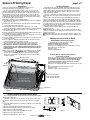
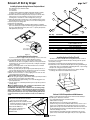
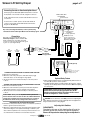
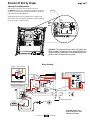
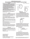
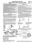
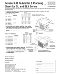
Installation/Operating Instructions
Scissor Lift SLX Video Projector Lift by Draper
Caution:
Important Safety Instructions
Read all instructions completely before proceeding.
DANGER: To reduce risk of shock:
1 Always disconnect power from lift before cleaning.
WARNING–To reduce risk of burns, fires, electric shock or injuries to persons:
2 Disconnect power from lift before putting on or taking off parts.
3 Use this lift only for its intended use as described in these instructions. Do
not use attachments not recommended by the manufacturer.
4 Never operate this lift if it has a damaged cord or plug. If it is not working
properly, call your dealer or the manufacturer for assistance/repair.
5 Keep cords away from heated surfaces.
6 Never operate lift with air opening blocked. Keep the air openings free of lint,
hair, and the like.
7 Never drop or insert any object into any opening.
8 Do not use outdoors.
9 Route cords and cables as shown in the instructions.
10 WARNING: Rick of Electric Shock—connect this product to a
properly grounded electrical supply.
Important installation/operating Instructions
WARNING: To prevent injury, this apparatus must be securely attached to
the building structure in accordance with the instructions.
11 Test lift prior to installation. Please Note: Packaging must be removed from
lift before testing.
12 Follow instructions carefully. Installation contrary to instructions invalidates
warranty.
13 Do not obstruct operation of Scissor Lift SLX with fingers or any object.
Serious injury or damage could result.
14 Lift is intended for use with product weighing not more than 350 pounds.
15 Scissor Lift SLX is designed to accommodate ceiling suspended equipment.
Equipment should not be allowed to rest on optional ceiling closure
during operation (refer to section titled “Installing Projector”).
16 Entire bottom of unit must be unobstructed to permit proper operation.
Sufficient clearance must be allowed below projector or optional ceiling closure:
10' for Model SLX10, 14' for Model SLX14, etc.
17 Unit must be installed level (use a carpenter’s level).
18 Unit operates on 115V AC 60 Hz. current. 10.93 amps current draw (3.93
amps for lift, 7 amps for outlet).
19 Verify the show position when testing lift. Make required changes by referring
to adjustment instructions on page 4 of this document.
20 The maintenance/service factory limit setting must not be adjusted to a lower
position than the preset factory limit setting. In addition, Draper does not
recommend setting show position at the maintenance/service position—for
example, if you wish to have 8' show position, order a lift with at least a 10'
maintenance position.
21 When the Scissor Lift SLX is to be installed in “other space used for
environmental air” the optional environmental air space housing must
be installed per instructions to isolate the lift from the “other space
used for environmental air.”
22 When Scissor Lift SLX is NOT installed in environmental air space housing and optional ceiling closure, the ALTERNATE wiring for up limit switch may
be used (see Alternate Wiring schematic on page 5).
CAUTION: Before servicing unit, disconnect hardwired control and any
remote control.
Note: Unit has been thoroughly inspected and tested at factory and found to be
operating properly prior to shipment.
WARNING/AVERTISSEMENT
RISK OF ELECTRIC SHOCK. DO NOT OPEN
RISQUE DE CHOC ELECTRIQUE. NE PAS OUVRIR.
Electrical Connections
Unit operates on 115V AC, 60 Hz. current. 10.93 amps current draw (3.93 amps
for lift, 7 amps for outlet). Opening the electrical box exposes terminals for field
connections. Unit is shipped with internal wiring complete.Wire to connect unit
to power supply should be furnished by installer. Connections should be made
in accordance with wiring diagram, and wiring should comply with national and
local electrical codes. An appropriate disconnect device shall be provided as part
of the building installation. All operating switches should be “off” before power is
connected.
Caution:
Beware
of pinch
points
Copyright © 2014 Draper Inc. Form ScissorLiftSLX_Inst14-R Printed in U.S.A.
Caution: Make sure electrical supply has been disconnected before
attempting to connect Scissor Lift to electricity.
Scissor Lift should be operated and checked prior to installing projector and/or
optional ceiling closure.
Low Voltage Control Switch shown below comes with 75' of non-plenum rated
cable and should be plugged in to Control Panel on top frame of lift for control
of the "Up" and "Show" positions. Momentary Key Switch shown below comes
with 75' of cable and should be plugged in to Control Panel on top frame of lift for
control of the "Service" position.
Planning
1 Based on screen location and projector specifications, determine proper
position for projector installation.
2 Confirm that there is adequate space for installation and operation. Minimum
clearance above ceiling level varies according to Scissor Lift model, plus height
of projector, optional mounting bracket, optional ceiling closure, and optional
Environmental Air Space Housing.
3 Arrange to provide service access to the unit.
4 Maximum lifting capacity is 350 Lbs.
As Soon As Scissor Lift Arrives
1 Open carton and inspect for damage.
2 Locate the following parts:
A.The unit itself
B.Controls
C.Optional equipment: Environmental Air Space Housing, Universal
Projector Mount, closure panel or ceiling finish kit (all ship in separate
cartons).
3 Test lift prior to installation. Please Note: Packaging must be removed from
lift before testing.
Operation
Before operating or testing the unit, make sure the
packaging has been removed from the unit. This can be
accomplished by removing the eight screws (four per side)
holding the packing frame to the lift. Once the packaging is
all removed, operate the lift in the "Up" direction, so the lift's
control encoder will recognize it's "home" location. Until you
do this, the Down function will not work.
When unit is first operated, be cautious! If unit fails
to operate properly, press “off” and recheck electrical
connections before proceeding. Cycle unit down and
up several times to confirm satisfactory operation. You
must also do this if the Scissor Lift ever loses or is
disconnected from the power.
Caution: Do not pull on or touch safety belt when unit
is in motion. If belt locks, the cables will unspool.
Caution: Obstructing bottom pan may cause cables
to unspool.
LVC-S
Up &2¾"
Show
7/8"
4½"
Front
SP-KSM
Service
UP
UP
Side
OFF
OFF
DOWN
DOWN
Standard Single Station Low Voltage Control (See Fig.
1)—One three-button switch with “Up”, “Down”, and “Off”
buttons. Lift starts up or down when appropriate button
Figure 1
is pressed, and may be stopped by pressing “Off” button.
Factory set limit switches stop lift automatically when
projector is in “show” position. One momentary key switch lowers lift from “Show”
to “Service” position.
Optional Multiple Station Control—Optional, moves lift from “Stored” to “Show”
position only. Each switching station has a three-button switch with “Up”, “Down”,
and “Off” buttons. Lift starts up or down when appropriate button is pressed,
and may be stopped by pressing “Off” button. Factory set limit switches stop lift
automatically when projector is in “Show” position.
Optional Key Operated Switch—If ordered, the standard LVC-S can be replaced
with a second single station, momentary key-operated three position (up/off/down)
switch. Multiple Station Control required for this option. Moves lift from “stored” to
“show” position only.
Optional Infrared or Radio Frequency Remote Control—If ordered, a threebutton transmitter is provided, with “up”, “down”, and “stop” buttons. Unit starts up
or down when appropriate button is pressed, and may be stopped by pressing
“off” button. Factory set limit switches stop unit automatically when projector is in
“show” position. Only controls "show" and "stored" positions.
Optional RS232 Control—For Serial communication an R2D7 Serial
Communications Interface is optionally available.
Low Voltage Trigger—Input provided for Low Voltage
Trigger from projector (see diagram on page 4).
Scissor Lift SLX is approved to UL 2442 and CSA C22.2 No. 60065-03.
Please Note: Scissor Lift SLX must be installed in accordance with the
requirements of the Local Building Codes, the Canadian Electrical Code (CEC),
CAN/CSA C22.1 and the National Electric Code (NEC), NFPA 70, as required. An
appropriate disconnect device shall be provided as part of the building installation.
If you encounter any difficulties installing or servicing your Scissor Lift SLX, call your
dealer or Draper, Inc. in Spiceland, Indiana, 765-987-7999, or fax 765-987-7142.
Scissor Lift SLX by Draper
Hanging Unit
Please note: If using Environmental Air Space Housing option, go to
Environmental Air Space Housing instructions on page 7.
The Scissor Lift may be installed in a variety of ways; recessed above the
ceiling, or suspended below the ceiling. The lift should be supported by four ½"
threaded mounting rods or bolts with locking nuts. If ceiling recessed, the entire
unit (including the projector) should set approximately 1½" above the finished
ceiling in its “stored” position. The threaded rods should pass through the corner
mounting flanges and be secured by nuts above and below. The unit should then
be guy wired or blocked to prevent swinging.
All installations should observe the following guidelines:
1 If installing above a hard ceiling, optional Draper Access Panels are available to
allow access to the unit.
2 Installer must ensure that all fasteners and supports are of adequate strength
to
securely support Scissor Lift and projector.
3 Fastening methods must be suitable for mounting surface, and securely
anchored so that vibration or abusive pulling on unit will not weaken installation.
4 Unit should be level, with weight shared more or less equally by all four
threaded mounting rods.
5 Bottom of unit must be unobstructed after installation. Sufficient clearance must
be allowed below projector or optional ceiling closure.
6 Unit must be secured independent from suspended ceiling and do not use unit
to support adjacent ceiling, light fixtures, etc.
7 Unit to be installed so when lowered to its lowest point, it is a minimum of 8 feet
(2.44 m) above the floor.
8 Do not complete the ceiling below unit until electrical connections have been
completed and unit has been operated successfully.
9 We recommend that safety cables be attached to the Scissor Lift SLX for
added security (a sound installation practice with overhead equipment).
10 When the Scissor Lift SLX is to be installed in “other space used for
environmental air” the optional Environmental Air Space Housing must be
installed per instructions to isolate the lift from the “other space used for
environmental air.”
11 When Scissor Lift SLX is NOT installed in environmental air space housing and
optional ceiling closure, the ALTERNATE wiring for 'UP' limit switch may be
used. Disconnect both BLACK (BK) wires from 'UP' limit switch and quick
connect them together using the provided jumper cable (see Alternate Wiring
schematic on page 5).
page 2 of 7
Installing Projector
Generally, the video projector should be suspended from the Projector Pan
according to projector manufacturer’s instructions and recommended standard
ceiling mounting hardware. Projector should be bolted to projector pan as in a
normal ceiling mounting. Equipment should not be allowed to rest on optional
ceiling closure during operation.
The Scissor Lift SLX has a grounded 115V AC, 60 Hz power cord for projector
power supply. The power cord is laced down the back scissor and is “hot” at all
times.
Control cables should be laced through our Cable Management System on
rear scissor mechanism only. Route the cables and attach with plastic wire ties
similar to factory installed power cable. Make sure to use flexible cables. Plenum
rated cables are typically too stiff and should not be used. Installer is responsible
for ensuring cables do not stretch, kink, or interfere with the scissor mechanism as
the unit raises and lowers. This will ensure that cords do not become tangled and
damaged during Scissor Lift SLX operation.
Unit and projection system should be operated, checked and adjusted as
necessary at this time.
NOTE: Immediately upon completion of the surrounding ceiling, units should be
operated to confirm that optional ceiling closure panel stops just short of touching
ceiling in closed position.
Warning: Keep fingers and other objects away from automatic ceiling closure
and scissor mechanisms when unit is operating. Serious injury or damage could
result.
Adjusting for Level or Center of Gravity
Preferred Method—Adjusting Projector Pan
1
2
3
4
5
6
The Projector Pan can be moved forward or back.
Make sure Bottom Pan is supported.
Remove the Lifting Cable Bar (see Fig. 2).
Remove screws holding Projector Pan on Bottom Pan (see Fig. 2).
Move Bottom Pan forward or back.
Replace screws.
Replace Lifting Cable Bar.
Secondary Method—Adjusting Lifting Cable Bar
(if above does not work)
Run the unit to its "Service" position and make sure pan is level. Try and
set so that pan is not more than ¾" out of level. However, the pan
does not have to be perfectly level, as long as the positioning is
consistent and repeatable in "Show" and "Closed" positions.
1 Make sure Bottom Pan is supported.
2 Remove screws holding Lifting Cable Bar to the Bottom Pan (see Fig.
2).
3 Move Lifting Cable Bar forward or back (see Fig. 2).
4 Replace screws.
5 Check level again. If still not level, repeat.
Attachment points
for Lifting Cables
Lifting
Cable Bar
Projector Pan
3
/8"-18 x 1" hex head cap
screws for attaching Lifting
Cable Bar to Bottom Pan
¼"-20 x ¾" hex head
cap screws for attaching
Projector Pan to Bottom Pan
7"
Bottom Pan
Figure 2
21/16"
315/16"
Installing Optional Universal Projector Mount
If you ordered the unit with optional Universal Projector Mount pre-installed,
disregard these instructions.
If you did not order the mount pre-installed, you will need to install a new
Projector Pan, which includes the Universal Projector Mount's rectangular
plate.
1 Lower unit until the Bottom Pan is resting on a tabletop or other stable and
sturdy surface.
2 Remove Lifting Cable Bar from Bottom Pan (see Fig. 2).
3 Remove bolts holding Projector Pan to Bottom Pan (see Fig. 2).
4 Remove Projector Pan and set aside.
5 Place new Projector Pan with Universal Mount into place.
6 Re-attach Projector Pan to Bottom Pan.
7 Re-attach Lifting Cable Bar to Bottom Pan.
www.draperinc.com
12"
7"
21/16"
315/16"
12"
(765) 987-7999
Figure 3
Scissor Lift SLX by Draper
page 3 of 7
Installing Projector Using Universal Projector Mount
1
2
3
4
5
The Universal Projector Mount includes:
-2 x long arms
-4 x short arms
-4 x M3, 4 x M4, 4 x M5 and 4 x M6 mounting bolts (30 mm in length)
-4 spacers (½" [13 mm], 5/8" [16 mm], ¾" [19 mm], 7/8" [22 mm])
Determine which size mounting bolts suit your projector, and set others
aside. They are no longer required. If your projector has only three
mounting holes, set aside one of the mounting arms (see Fig. 3).
Attach the appropriate mounting arms to the rectangular plate via center
bolt. Spread out the arms so each end is over one of the mounting holes.
Connect projector mounting arms.
Tighten the mounting bolts.
Use the ¼" (6.35 mm)-20 bolts and springs which hold the rectangular
plate to the bottom pan to adjust roll and tilt (the springs will ensure that the
projector is held still during motion). The center 5/16" (8 mm) bolt provides
Yaw adjustment (see Fig. 4).
8
9
2
3
7
4
6
7
5
1
Item Qty Part Number
Description
1
1
C028.546
Frame, SLX Closure Trim
2
1 C044.181.07SA
Panel, SLX Assembled Closure
3
2 C002.845.07SA
Bracket, SLX Closure
44 C077.035.49 Rod 3/8"-16 x 177/8" L Threaded , Zinc
5
8
C013.050
Washer .375 I.D. x .875" O.D.
x .064" TK GRD 2 Zinc Flat
6
8
C020.082
Screw, 10-16 X ½" 6 Lobe
Truss Head AB E-White
716 C018.027
Nut, 3/8"-16 Hex GRD 2 NSF
84 C020.322 Screw, 5/16"-18 x ¾" Long Grade 5 HH Zinc
94 C018.045
Nut, 5/16"-18 Zinc Hex KEPS
Detail: ¼" (6.35 mm)-20
Bolts and Spring
Spring
¼" (6.35 mm)-20
Bolt and Washer
Figure 5
Figure 4
Installing Optional Ceiling Closure
If your Scissor Lift SLX is equipped with optional ceiling closure, it can be used
as is, or in conjunction with a square of existing ceiling tile (see Fig. 5).
1 If installing with ceiling tile, you may need to cut tile so that its overall
dimensions are the same as (or slightly less than) the closure panel. Place tile
into trim frame. Lay closure panel on top (back side) of ceiling tile, and tighten
screws to hold in place.
2 Attach provided angle brackets to side of Bottom Panel of Scissor Lift SLX.
3 Attach 5/16" threaded rods to angle bracket.
4 Run unit “up” until bottom pan stops at highest position. Mark position on 5/16"
rods even with ceiling level and cut to length (remove from pan if convenient).
5 Run unit “down” until bottom pan stops at “show” position.
6 Attach closure to lower end of 5/16" rods by slipping into four corner slots and
secure with nuts above and below slots.
Caution: Make sure nuts are completely tightened.
7 Run unit “up” again to highest position. Measure distance by which panel fails to
reach required “closed” height for surrounding ceiling.
8 Run unit “down” then re-adjust mounting of 5/16" rods in traveling grid to raise
panel required distance.
9 Test unit operation to confirm that panel will stop in closed position just before
touching ceiling.
Caution: DO NOT hang from, "ride" or pull down on the unit. This could
create a failure and cause damage and/or injury.
PLEASE NOTE: Immediately upon completion of the surrounding ceiling,
unit should be operated to confirm that optional ceiling closure panel by
Draper or by others stops 1/8" short of touching ceiling in closed position.
If closure panel touches, the motor may continue operating after the lift is
closed. If it continues to cycle once the lift is closed, a motor failure may
occur.
For Additional Safety:
1 Be sure the nuts that attach the threaded
rods to the closure panel are tight.
2 Wrap a plastic wire tie around the mounting
tab and the threaded rod at all four corners
of the closure panel (see drawing).
Please Note: Do NOT use a
paper-covered or similar wire tie—
use only plastic wire ties for
maximum safety.
www.draperinc.com
Installing Optional Ceiling Trim Kit
The Scissor Lift SLX is available with a Ceiling Trim Kit, which consists of
the lower section of the Environmental Air Space Housing and the optional
closure panel (see Fig. 6).
1 Install Scissor Lift SLX as previously described in these instructions.
2 Install bottom section of Environmental Air Space Housing and Trim Ring in
opening. This can be accomplished by suspending with wire, or by mounting
directly to the ceiling joists (if space permits).
3 Install projector and attach optional ceiling closure to Scissor Lift SLX,
according to the instructions included in this document.
Lower section of
Environmental Air
Space Housing
Trim Ring
Ceiling tile
(by others)
Figure 6
Scissor Lift SLX Inspection and Maintenance
Draper recommends inspecting the Scissor Lift SLX at least annually or
every 300 cycles—whichever comes first.
A recommended maintenance schedule includes:
-Cables: Check for fraying.
-Drive Chain: Check for rust, breaks, secure attachment.
-Fasteners along scissor arm assemblies: Make sure they are not loose. If
any are loose, hand tighten the nuts. (Please Note: there is no need to
tighten nut in the top scissor which slides back and forth in the side slot in
the lift. Tightening this fasteners assembly will cause the unit to lock up
and lead to damage to the unit.)
-Closure: Make sure threaded rod remains seated firmly in the closure
panel corners, and that nuts remain tight. If they are loose, tighten them.
(765) 987-7999
Scissor Lift SLX by Draper
page 4 of 7
Connecting Controls to Data Cable Splitter Board
Controls plug into the Data Cable Splitter Board, which is located on
the Top Frame on the front side of the lift, using RJ14 connectors.
DETAIL OF DATA CABLE
SPLITTER BOARD
For IR or RF Remote Control, use data cable with RJ14 connectors
on both ends.
Any control, including automated dry contact systems, being
connected to the wall switch input MUST send a momentary signal.
Pin
123456
YGRB
Please Note:
Pin
123456
YGRB
Data cable connections must be made using
electrically straight 4-conductor modular cable
(RJ14). If making your own cables, this means
colors do not cross over: blue leads to blue, green
to green, etc. (see diagram below).
Pin
123456
YGRB
LVT
RP/RQ
RP/RQ
KEY
For serial control of "Show" position, use data cable with RJ14
connectors on both ends and an R2D7 Serial Control Interface.
Plug into the "RP/RQ" input.
WALL
Function Indicator
Low Voltage Trigger
(6-24 VDC)
(No +/- wiring requirement)
RP/RQ Bus Ports for
remote controls such as
IR Eye, RF Receiver, LED
Wall Switch and RS232
LVC-S
Red - Down
Black - Com
Black - Com
Blue - Up
Pin
123456
YGRB
SP-KSM
Green
Black
DCU
Yellow
Low voltage
wiring by others
Green
Black
Yellow
Pin
654321
B R GY
CLEARING THE SHOW POSITION AT CURRENT SHOW POSITION:
1 Move lift to the show position.
2 While lift is at the show position press and hold the Key Up toggle
switch and release once the Lift begins moving upward.
3 The show position is now cleared and ready for a new show position
to be set.
CLEARING THE SHOW POSITION AT THE MAINTENANCE POSITION:
1 Move lift to the maintenance position.
2 While lift is at the maintenance position press and hold the Key Down
toggle switch and release once the Lift begins moving upward.
3 The show position is now cleared and ready for a new show position
to be set.
PLEASE NOTE: At this point the Key Switch will not operate until
the new “Show Position” has been set. Also the 3-Button Wall Switch
changes into a maintain, push and hold type button, for continuous
movement. This allows for easy setting of new “Show Position”)
PROCEDURE FOR SETTING SHOW POSITION:
1 Now that the show position has been cleared, use wall switch up and down
buttons to get lift into desired show position.
2 While lift is at desired show position, press and hold the Key Down toggle
switch until lift begins to move upward. Lift will begin a calibration cycle
where it will move upward for two seconds, stop then move down for one
second and then the Lift will return to the desired show position.
www.draperinc.com
Pin
123456
YGRB
R2D7 (Optional)
To RS232 Port:
Yellow = Rx (Data from control system)
Green = Tx (Data to control system)
Red = Unused
Black = Gnd (Signal Ground)
Optional Delay Feature
1When the Optional Delay Feature is installed the Delay Switch must be in the "Delay On" position for normal operation.
2If the Optional Delay Feature is installed and the "Show Position" requires adjusting, then the "Delay Switch" must be switched to OFF while adjusting the show position.
PLEASE NOTE: If the Scissor Lift loses power, the DOWN
function will not work until you operate the lift in the UP
direction using the wall switch. This allows the lift's control
encoder to recognize it's "home" location.
CAUTION: Be sure all switches are in OFF position before adjusting limit
switch. Always be prepared to shut lift off manually when new adjustment is
being tested. Please refer to wiring diagram.
Adjusting Limit Switches
PLEASE NOTE:
Changing the fully open or fully closed position will reset the
electronic controls and cuase the lift to operate improperly.
Please call Draper before attempting these adjustments.
(765) 987-7999
Scissor Lift SLX by Draper
page 5 of 7
Adjusting FULLY DOWN position
Limit switches for the Scissor Lift SL are preset at the factory.
The DOWN limit switch is set for the fully down (maintenance) position for
the size lift you have ordered. The limit switch assembly is located inside
the lift and behind the Lifting Cable Drum.
DOWN
The Down limit switche shown in the drawing are for setting the "Fully
Down" position. This can be adjusted manually by loosening or tightening
the screw to increase or reduce the travel.
ROTATE
TO
ADJUST
DOWN
Limit
Switch
Caution: The maintenance/service factory limit setting must
not be adjusted to a lower position than the preset factory limit
setting. In addition, Draper does not recommend setting show
position at the maintenance/service position.
Wiring Schematic
ALTERNATE ‘UP’ LIMIT SWITCH WIRING
NC
OR
NC
BK
BK
BK
WH
OR
RD
2 Cond. Cable
Down
Limit
Switch
BN
BK
BK
Jumper*
NC RD
NOTE: This CANNOT be
used when lift is installed in
Environmental Air Space Housing
and Optional Ceiling Closure
UCD
BN
RD
WH
BK
YL
YL/GN
Up
Limit
RD Switch
NC OR
BK
NC BK
Delay Switch
(on position)
RD
OR
Run Cap
60 MFD
BK
RD Motor
Down
BK
BK
BK
WH
OR
RD
BL
Up
YL/GN
BK
BK
AC
BK
AC
WH
COM
RD
N.O.
N.C.
OR
BK
Optional Delay Assembly
115V ac, 7A 60 Hz Outlet WH
RD
Attached to lower pan
WH
BK
WH
BK
GN
N
115V ac,
Supply
Up
Limit
RD Switch
WH
Dashed wiring by electrician
FRONT OF DATA CABLE
SPLITTER BOARD
BACK OF DATA CABLE
SPLITTER BOARD
RD
WH
Encoder
KEY
WALL
LVT
RP/RQ
RP/RQ
BK
RD
BK WH
RD
WH
*Black (BK) Jumper wire is
located in the plastic sleeve
with these instructions.
www.draperinc.com
(765) 987-7999
Scissor Lift SLX by Draper
page 6 of 7
Scissor Lift SLX Dimensions
9
/16" (14 mm)
x4
Table A
385/16"
(973
mm)
363/16"
(919
mm)
ClosedExtended
Model Height
Height
SLX10
141/16"10'7"
SLX14
165/16"14'2"
SLX17
189/16"17'8"
SLX21
2013/16"21'3"
SLX24
231/16"24'9"
SLX28
255/16"28'5"
359/16" (903 mm)
3711/16" (957 mm)
Top View
See
Table
A
/8"
(3.175
mm)
1
35" (889 mm)
36¼" (921 mm)
391/16" (992 mm)
42" (1067 mm)
357/16" (900 mm)
371/16" (941 mm)
42" (1067 mm)
19/16"
(39.6875
mm)
Front View
20¾"
Side View
41¾"
41½"
5"
48½"-22½"
19"
Front/Back View
www.draperinc.com
Side View
(765) 987-7999
Scissor Lift SLX by Draper
page 7 of 7
Installing Optional Environmental Air Space Housing
“other space used for environmental air.” Includes trim ring for ceiling opening.
1 Attach Environmental Air Space Housing top frame to top of Scissor Lift
SLX with bolts provided.
2 Install top panel to Environmental Air Space Housing frame.
3 Attach assembly to overhead structure. Allow clearance between Environmental Air Space Housing top and structure for ease of future access.
4 Install side and end panels, and trim frame.
The Environmental Air Space Housing is shipped in pieces, and must be
assembled by the installer. The height of the Environmental Air Space Housing is set by punching out the knockouts at the desired locations then using
screws to connect side panels. It is recommended that an access panel be
installed in the ceiling to allow future access. The optional Environmental Air
Space Housing must be installed per instructions to isolate the lift from the
Please Note: The factory wiring of 'UP' Limit Switch MUST ALWAYS
be used when SLX is installed in Environmental Air Space Housing
and Optional Ceiling Closure.
11
11
11
11
11
7
11
1
11
3
3
11
8
5
4
3
9
Knockouts
6
FRONT /
4
BACK
10
Do not use
electrical knockouts
on bottom sections
2
Item Qty Part Number
Description
1
1 C028.544.02SA
Frame, SLX Plenum
2
1 C028.545.07SA
Frame, SLX Trim Ring
3
4
C044.178SA
Panel, SLX Plenum Side
4
4
C044.180SA
Panel, SLX Plenum End
5
2
C044.179SA
Panel, SLX Middle End
6
2
C044.177SA
Panel, SLX Plenum Middle Side
7
1
C095.123SA
Cover, SLX Plenum
8
28
C020.325
Screw, 8-32 x 3/8" Type 1 HWH
9
40
C018.051
Nut #8-32 Zinc Hex KEPS
10
12
C013.070 Washer, .188 I.D. x .5 O.D. x .07" TK Nylon Flat
11
24
C020.112
Screw, 8-32 x 3/8" Type F HWH
Caution: Be careful when handling Environmental Air Space
Housing Panels. The panels could have sharp edges.
www.draperinc.com
(765) 987-7999
9
5
3