1
USER'S MANUAL
Thank you very much for purchasing the EGX-300.
•
To ensure correct and safe usage with a full understanding of this product's performance, please be sure
to read through this manual completely and store it in
a safe location.
•
Unauthorized copying or transferral, in whole or in
part, of this manual is prohibited.
•
The contents of this operation manual and the
specifications of this product are subject to change
without notice.
•
The operation manual and the product have been
prepared and tested as much as possible. If you find
any misprint or error, please inform us.
•
Roland DG Corp. assumes no responsibility for any
direct or indirect loss or damage which may occur
through use of this product, regardless of any failure to
perform on the part of this product.
•
Roland DG Corp. assumes no responsibility for any
direct or indirect loss or damage which may occur
with respect to any article made using this product.
For the USA
FEDERAL COMMUNICATIONS COMMISSION
RADIO FREQUENCY INTERFERENCE
STATEMENT
This equipment has been tested and found to comply with the
limits for a Class A digital device, pursuant to Part 15 of the
FCC Rules.
These limits are designed to provide reasonable protection
against harmful interference when the equipment is operated
in a commercial environment.
This equipment generates, uses, and can radiate radio
frequency energy and, if not installed and used in accordance
with the instruction manual, may cause harmful interference
to radio communications.
Operation of this equipment in a residential area is likely to
cause harmful interference in which case the user will be
required to correct the interference at his own expense.
NOTICE
Grounding Instructions
Do not modify the plug provided - if it will not fit the outlet,
have the proper outlet installed by a qualified electrician.
Check with qualified electrician or service personnel if the
grounding instructions are not completely understood, or if in
doubt as to whether the tool is properly grounded.
Use only 3-wire extension cords that have 3-prong
grounding plugs and 3-pole receptacles that accept the tool’s
plug.
Repair or replace damaged or worn out cord immediately.
Operating Instructions
KEEP WORK AREA CLEAN. Cluttered areas and benches
invites accidents.
Unauthorized changes or modification to this system can void
the users authority to operate this equipment.
DON’T USE IN DANGEROUS ENVIRONMENT. Don’t
use power tools in damp or wet locations, or expose them to
rain. Keep work area well lighted.
DISCONNECT TOOLS before servicing; when changing
accessories, such as blades, bits, cutters, and like.
The I/O cables between this equipment and the computing
device must be shielded.
REDUCE THE RISK OF UNINTENTIONAL STARTING.
Make sure the switch is in off position before plugging in.
USE RECOMMENDED ACCESSORIES. Consult the
owner’s manual for recommended accessories. The use of
improper accessories may cause risk of injury to persons.
NEVER LEAVE TOOL RUNNING UNATTENDED.
TURN POWER OFF. Don’t leave tool until it comes to a
complete stop.
For Canada
CLASS A
NOTICE
This Class A digital apparatus meets all requirements of the
Canadian Interference-Causing Equipment Regulations.
CLASSE A
AVIS
Cet appareil numérique de la classe A respecte toutes les
exigences du Règlement sur le matériel brouilleur du
Canada.
ROLAND DG CORPORATION
1-6-4 Shinmiyakoda, Hamamatsu-shi, Shizuoka-ken, JAPAN 431-2103
MODEL NAME
: See the MODEL given on the rating plate.
RELEVANT DIRECTIVE : EC MACHINERY DIRECTIVE (98/37/EC)
EC LOW VOLTAGE DIRECTIVE (73/23/EEC)
EC ELECTROMAGNETIC COMPATIBILITY DIRECTIVE (89/336/EEC)
WARNING
This is a Class A product. In a domestic environment this product may cause radio interference in which
case the user may be required to take adequate measures.
Table of Contents
To Ensure Safe Use .............................................................................................................................. 2
About the Labels Affixed to the Unit .................................................................................................5
Pour utiliser en toute sécurité .......................................................................................................6
À propos des étiquettes collées sur l'appareil ...............................................................................9
Part 1 Startup
1-1
Checking the Accessories ............................................................................................................... 11
1-2
Part Names and Functions ............................................................................................................. 12
1-3
Installation and Connections ........................................................................................................... 14
1-4
Installing the Software ..................................................................................................................... 16
1-5
Setting the Connection Parameters ............................................................................................... 19
1-6
Loading a Workpiece for Cutting .................................................................................................... 20
1-7
Loading a Cutter ............................................................................................................................... 21
1-8
Vacuum Cleaner Connection .......................................................................................................... 26
1-9
Setting the Origin (Home Position) ................................................................................................ 27
1-10 Cutting Condition Setting ................................................................................................................. 28
1-11 Setting the Z1 and Z2 Position ...................................................................................................... 31
1-12 Sending Cutting Data ....................................................................................................................... 32
1-13 Finishing ............................................................................................................................................. 33
Part 2 User's Reference
2-1
Cutting Area ....................................................................................................................................... 35
2-2
Operating Each Function ................................................................................................................. 36
2-3
Explanation of the Display Menus .................................................................................................. 40
2-4
Maintenance ...................................................................................................................................... 43
2-5
Troubleshooting ................................................................................................................................. 47
2-6
Error Messages ................................................................................................................................. 49
2-7
Other Messages ............................................................................................................................... 50
2-8
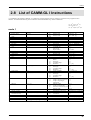
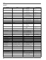
List of CAMM-GL I Instructions ...................................................................................................... 51
2-9
Device Control Instructions ............................................................................................................. 54
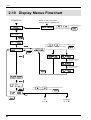
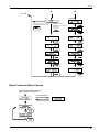
2-10 Display Menus Flowchart ................................................................................................................ 56
2-11 List of Options ................................................................................................................................... 58
2-12 Specifications .................................................................................................................................... 59
Index ............................................................................................................................................................ 61
Windows® and Windows NT® are registered trademarks or trademarks of Microsoft® Corporation in the United States and/or other
countries.
i486 and Pentium are registered trademarks of Intel Corporation in the United States.
IBM is a registered trademark of International Business Corporation.
Copyright © 2001 Roland DG Corporation
http://www.rolanddg.com/
1
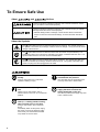
To Ensure Safe Use
About
and
Notices
Used for instructions intended to alert the user to the risk of death or severe
injury should the unit be used improperly.
Used for instructions intended to alert the user to the risk of injury or material
damage should the unit be used improperly.
* Material damage refers to damage or other adverse effects caused with
respect to the home and all its furnishings, as well to domestic animals or
pets.
About the Symbols
The
symbol alerts the user to important instructions or warnings. The specific meaning of
the symbol is determined by the design contained within the triangle. The symbol at left means
"danger of electrocution."
The
symbol alerts the user to items that must never be carried out (are forbidden). The
specific thing that must not be done is indicated by the design contained within the circle. The
symbol at left means the unit must never be disassembled.
The
symbol alerts the user to things that must be carried out. The specific thing that must
be done is indicated by the design contained within the circle. The symbol at left means the
power-cord plug must be unplugged from the outlet.
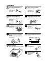
Do not disassemble, repair, or
modify.
Use only with the power cord
included with this product.
Doing so may lead to fire or abnormal
operation resulting in injury.
Use with other than the inculuded power
cord may lead to fire or electrocution.
Ground the unit with the ground
wire.
Do not use with any electrical power
supply that does not meet the
ratings displayed on the unit.
Failure to do so may result in risk of
electrical shock in the even of a mechanical
problem
Do not use while in an abnormal
state (i.e., emitting smoke, burning
odor, unusual noise, or the like).
Doing so may result in fire or electrical
shock.
Immediately switch off the power, unplug
the power cord from the electrical outlet,
and contact your authorized Roland DG
Corp. dealer or service center.
2
Use with any other power supply may lead
to fire or electrocution.
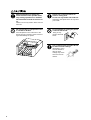
Do not use with a damaged power
cord or plug, or with a loose
electrical outlet.
When not in use for extended
periods, unplug the power cord from
the electrical outlet.
Use with any other
power supply may
lead to fire or
electrocution.
Failure to do so may
result in danger of
shock, electrocution,
or fire due to
deterioration of the
electrical insulation.
Do not injure or modify the electrical
power cord, nor subject it to
excessive bends, twists, pulls,
binding, or pinching, nor place any
object of weight on it.
When unplugging the electrical
power cord from the power outlet,
grasp the plug, not the cord.
Unplugging by pulling the cord may damage
it, leading to fire or electrocution.
Doing so may
damage the
electrical power
cord, leading to
electrocution or
fire.
Do not allow liquids, metal objects
or flammables inside the machine.
Such materials
can cause fire.
Unpacking, installation, and moving
must be carried out by two or more
persons.
Failure to do so may result in falling of the
unit, leading to injury. (The machine weighs
28.5 kg (62.8lb.). )
Install on a stable surface.
Failure to do so
may result in
falling of the unit,
leading to injury.
Do not block the ventilation holes.
Blocking the ventilation holes at the rear of
the unit may prevent heat radiation and
cause fire.
Do not carelessly insert the hands
while in operation.
Perform dry cutting with no cutting
oil.
Doing so may result in injury (during manual
operation.).
Such materials can
cause fire.
When you're finished,
wash your hands to
rinse away all
cuttings.
3
Before attempting to replace the
motor brushes or the spindle motor,
stop cutting operations on the EGX300 and allow to stand for an hour or
so.
Please use a vacuum cleaner to
remove cutting dust.
Do not use any blower like airbrush.
Otherwise, dust spread in the air may harm
your health.
Failure to do so may result in burns from the
hot motor.
Do not operate if a transparent cover
is cracked or broken.
Do not attempt to unplug the power
cord with wet hands.
If the transparent cover at the front or the
side of the unit is cracked, contact a service
agent immediately for repairs.
Doing so may
result in electrical
shock.
Use a commercially available brush
to remove metal cuttings.
Attempting to use a
vacuum cleaner to
take up metal
cuttings may cause
fire in the vacuum
cleaner.
4
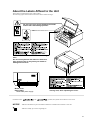
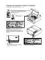
About the Labels Affixed to the Unit
These labels are affixed to the body of this product.
The following figure describes the location and content of these messages.
Do not insert your fingers between the heads
and the main unit during operation.
Handle tool with care.
Please use a vacuum cleaner to remove cutting
dust.
Do not use any blower like airbrush. Otherwise,
dust spread in the air may harm your health or
damage this machine.
Model name
Rating plate
Use a rated power supply.
In addition to the
NOTICE
Be sure to determine that the machine is not
moving at all, when operating the cover.
and
symbols, the symbols shown below are also used.
: Indicates information to prevent machine breakdown or malfunction and ensure correct use.
: Indicates a handy tip or advice regarding use.
5
Pour utiliser en toute sécurité
Avis sur les avertissements
Utilisé pour avertir l'utilisateur d'un risque de décès ou de blessure grave en
cas de mauvaise utilisation de l'appareil.
Utilisé pour avertir l'utilisateur d'un risque de blessure ou de dommage
matériel en cas de mauvaise utilisation de l'appareil.
* Par dommage matériel, il est entendu dommage ou tout autre effet
indésirable sur la maison, tous les meubles et même les animaux
domestiques.
À propos des symboles
Le symbole
attire l'attention de l'utilisateur sur les instructions importantes ou les
avertissements. Le sens précis du symbole est déterminé par le dessin à l'intérieur du triangle.
Le symbole à gauche signifie "danger d'électrocution".
Le symbole
avertit l'utilisateur de ce qu'il ne doit pas faire, ce qui est interdit. La chose
spécifique à ne pas faire est indiquée par le dessin à l'intérieur du cercle. Le symbole à gauche
signifie que l'appareil ne doit jamais être démonté.
Le symbole
prévient l'utilisateur sur ce qu'il doit faire. La chose spécifique à faire est
indiquée par le dessin à l'intérieur du cercle. Le symbole à gauche signifie que le fil électrique
doit être débranché de la prise.
Ne pas démonter, réparer ou
modifier.
Le non-respect de cette consigne pourrait
causer un incendie ou provoquer des
opérations anormales entraînant des
blessures.
Mettre l'appareil à la masse avec une
prise de terre.
Le non-respect de cette consigne pourrait
entraîner des décharges
électriques en
cas de problème mécanique.
Utiliser seulement avec une
alimentation de mêmes
caractéristiques électriques que
celles indiquées sur l'appareil.
Une utilisation avec toute autre alimentation
électrique pourrait provoquer un incendie
ou une électrocution.
6
N'utilisez que le cordon
d'alimentation fourni avec ce
produit.
L'utilisation avec un autre cordon
d'alimentation que celui fourni pourrait
entrainer un risque d'incendie ou
d'électrocution.
Utiliser seulement avec une
alimentation de mêmes
caractéristiques électriques que
celles indiquées sur l'appareil.
Une utilisation avec toute autre alimentation
électrique pourrait provoquer un incendie
ou une électrocution.
Ne pas utiliser avec une fiche ou un
fil électrique endommagé ou avec
une prise mal fixée.
Débrancher le fil lorsque l'appareil
reste inutilisé pendant une longue
période.
Une négligence à
ce niveau pourrait
provoquer un
incendie ou une
électrocution.
Une négligence à ce niveau pourrait
provoquer des décharges électriques,
une électrocution ou
un incendie dû à une
détérioration de
l'isolation électrique.
Ne pas endommager ou modifier le
fil électrique. Ne pas le plier, le
tordre, l'étirer, l'attacher ou le serrer
de façon excessive. Ne pas mettre
d'objet ou de poids dessus.
Saisir la fiche et non le fil électrique
lorsque vous débranchez.
Débrancher en tirant sur le fil pourrait
l'endommager et risquer de provoquer un
incendie ou une électrocution.
Une négligence à
ce niveau pourrait
endommager le fil
électrique ce qui
risquerait de
provoquer une
électrocution ou un
incendie.
Ne pas introduire de liquide, d'objet
métallique ou inflammable dans
l'appareil.
Ce genre de
matériel peut
provoquer un
incendie.
Lorsque vous déplacez l'appareil, le
saisir par sa base en aluminium et le
transporter à 2 personnes ou plus.
Si l'appareil est
saisi par la
plaque du
dessus, il peut
tomber et
entraîner des
blessures.
(Le poids total de
la machine est de 28.5 kg.)
Installer l’appareil sur une surface
stable.
Une négligence à
ce niveau pourrait
provoquer la chute
de l’appareil et
entraîner des
blessures.
Ne pas obstruer les trous de
ventilation.
Bloquer les trous de ventilation à l'arriére de
l'appareil peut empêcher la dispersion de la
chaleur et provoquer un incendie.
Faire attention de ne pas insérer ses
mains pendant le fonctionnement.
Faire des coupes à sec,
sans huile de coupe.
Ne pas respecter
cette consigne
peut provoquer
des blessures
(pendant le
fonctionnement
manuel).
L'huile de coupe peut
provoquer un incendie.
Quand vous avez
terminé d'utiliser
l'appareil, laver vos
mains pour bien
enlever tous les
copeaux.
7
Avant de tenter de remplacer les
balais de moteur ou le moteur à axe,
interrompre les opérations de coupe
du EGX-300 et attendre une heure ou
plus.
Ne pas respecter cette consigne peut
causer des brùlures car le moteur est très
chaud.
Utiliser un aspirateur pour nettoyer
les copeaux. N'utiliser aucun
appareil soufflant de l'air comme un
sèche-cheveux.
La poussière répandue dans l'air pourrait
nuire à votre santé.
Ne pas utiliser si un couvercle
transparent est fissuré ou brisé.
Ne pas essayer de débrancher le fil
avec des mains mouillées.
Si le couvercle transparent à l'avant ou sur
le côté de l'appareil est fissuré,
communiquer immédiatement avec un
agent de service pour le faire réparer.
Une négligence à
ce niveau pourrait
provoquer des
décharges
électriques.
Utiliser une brosse du commerce
pour retirer les rognures de métal.
Tenter de retirer les
rognures de métal à
l’aide d’un aspirateur
peut faire naître un
incendie dans
l’aspirateur.
8
À propos des étiquettes collées sur l'appareil
Ces étiquettes sont collées à l'extérieur de l'appareil.
Les dessins suivants indiquent l'endroit et le contenu des messages.
Ne pas insérer les doigts entre les têtes
d'impression et l'unité principale lorsque
l'appareil fonctionne.
Manipuler l'outil
avec précaution.
Veuillez utiliser un aspirateur pour enlever la
poussière.
Ne jamais utiliser de projecteurs d'air. La
poussière soufflée dans l'air peut causer des
problèmes de respiration et endommager votre
machine.
Nom du modèle
Étiquette des caractéristiques électriques
Utiliser l'alimentation appropriée
Vérifiez d'abord si la machine est à l'arrét
avant d'ouvrir le couvercle.
9
MEMO
10
Part 1
Part 1 Startup
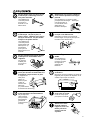
1-1 Checking the Accessories
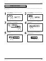
Check the following to make sure that you received all the items that were shipped along with the unit.
Power cord
Depth regulator nose
Character cutter
Wrenches
(diameter 3.175 mm)
(with cutter holder)
Collet
Collet
(For diameter 3.175 mm
(1/8 in.) cutters)
(For diameter 4.36 mm
(11/64 in.) cutters)
Hexagonal screw driver
Hexagonal wrench
Spare cutter securing screw
Adhesive sheet
Clamps
Vacuum adapter set
Motor brushes
Roland Software Package
CD-ROM
User's manual
11
Part 1
1-2 Part Names and Functions
Cover
Left side view
When opening the cover during operation, press the [ENTER/PAUSE]
key to pause operation.
Wait until operation stops completely, then open the cover. To resume
operation, close the cover and press the [ENTER/PAUSE] key again.
If you open the cover during operation without pressing the [ENTER/
PAUSE] key first, a single processing step is carried out, then operation
stops.
Serial connector
A serial (RS-232C)
cable is connected here.
Parallel connector
A parallel (printer)
cable is connected here.
External output
connector
Head
This moves the spindle (cutter) up and down). The
head performs X-axis, Y-axis and Z-axis movement.
Scale (for Checking the Z-axis Cutting Range)
This can be used to confirm the cutting range of the
Z axis.
The cutting range of the Z axis is 30 mm (1-1/8 in.).
According to the scale, the cutting range is 5 to 35
(mm) when the depth-regulator nose is installed, and
0 to 30 (mm) when not installed.
Z adjust screw
Table
Loosen the Z adjust screw if it
is necessary to adjust the depth
regulator nose for performing
engraving.
The table grips the workpiece to be cut.
Described on the
following page
Right side view
Cutter holder
Power switch
This is where the cutter
is mounted.
Power connector
The power cord included
with the machine is connected here.
Scale (for Checking the Z1 Position)
When using the depth-regulator nose,
this can be used to confirm the Z1
position that has been set.
Micrometer dial
Knurled
retainer nut
Depth regulator nose
This is adjusted when engraving a material
which does not have uniform thickness.
12
Depth regulator nose
Part 1
EMERGENCY STOP switch
This switch cuts the power supply and forces the
machine to stop, regardless of whether operation is
in progress. Press the EMERGENCY STOP
switch immediately if dangerous or abnormal
operation occurs.
Canceling an emergency stop
Rotate the red
portion of the
switch clockwise.
Spindle control
This is used to set the speed of the spindle motor.
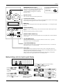
Liquid-crystal display
The settings and selection choices (or values) for the EGX-300 are shown on this display.
Error messages also appear here in the event of a problem.
MENU key
This key scrolls through the menu on the liquid-crystal display (i.e., it changes the panel
display).
ENTER/PAUSE key
This key is used to confirm settings, values, and selections made with the liquid-crystal
display.
When pressed during cutting, operation is paused.
SPINDLE TEST ON/OFF key
This key is used to start and stop the spindle motor. The spindle will not rotate while the
cover is open.
+Z (CUTTER UP) key
This key makes the cutter move in a positive direction on the Z axis (i.e., upward).
Movement is always at a constant speed.
-Z (CUTTER DOWN) key
This key makes the cutter move in a negative direction on the Z axis (i.e., downward).
Movement is always at a constant speed.
Arrow keys
Pressing an arrow key causes the XY table to move in the corresponding direction.
Holding down the key makes the XY table move faster (except during spindle rotation,
when the speed of movement does not change).
The arrow keys are also used together with the liquid-crystal display to manipulate
settings, select items, display other choices, and change values.
Making Settings with the Liquid-crystal Display
When coordinate values are displayed:
Use the
and
keys to move along the X axis.
Use the
and
keys to move along the Y axis.
Use the
and
keys to move along the Z axis.
Use the
and
keys to move the blinking
cursor (“ ”) and select the execution item.
Press the
key to execute.
Press the
and
keys to move the blinking
cursor (“ ”) and select the
setting item.
Press the
key to
display the next menu.
Press the
Press the
and
keys to change the value (or
selection choice), and then
press the
key to confirm.
Press the
and
keys
to move the blinking cursor (“ ”)
and select the setting item.
The value (or selection
choice) enclosed in angled
brackets (“< >”) indicates
the current setting.
key to confirm.
Press the
and
keys
to move the blinking cursor (“ ”)
and select the setting item.
Press the
key to confirm.
13
Part 1
1-3 Installation and Connections
Installation
Install on a stable surface.
Failure to do so
may result in falling
of the unit, leading
to injury.
Doing so may lead
to faulty operation
or breakdown.
NOTICE
Unpacking, installation, and moving
must be carried out by two or more
persons.
Failure to do so may result in falling of the
unit, leading to injury. (The machine weighs
28.5 kg (62.8lb.). )
Use within a temperature range of 5 to 40°C (41 to 104°F) and within a humidity range of 35 to 80%.
To prevent accidents, do not install in any of the following types of areas.
• Avoid use in areas subject to strong electric noise.
• Avoid use in areas subject to high humidity or dust.
• The EGX-300 generates heat when used, and should not be installed in an area with poor heat radiation
characteristics.
• Do not install in an area subject to strong
The space shown in the figure below is required for installation.
If you want to use the unit with a vacuum cleaner attached, see "1-8 Vacuum Cleaner Connection" and ensure that you have the required
amount of free space.
685 mm
(27 in.)
545 mm
(21-1/2 in.)
598 mm
(23-9/16 in.)
14
Part 1
Connections
Ground the unit with the ground
wire.
Do not use with any electrical power
supply that does not meet the
ratings displayed on the unit.
Failure to do so may result in risk of
electrical shock in the even of a mechanical
problem
Use with any other power supply may lead
to fire or electrocution.
Use only with the power cord
included with this product.
Use with other than the inculuded power
cord may lead to fire or electrocution.
NOTICE
Be sure that the power to both the computer and the main unit is switched off when connecting the cable.
Securely connect the power cord, computer I/O cable and so on so that they will not be unplugged and cause
failure during operation. Doing so may lead to faulty operation or breakdown.
The cable for computer connection is optional. Please purchase the appropriate cable for the type of computer and software used.
Right side
Left side
Crossover serial (RS-232C)
cable
(sold separately)
Use either a parallel
cable or serial cable
to connect.
Screw
Power switch
Parallel (Centronics)
cable
(sold separately)
Screw
Lock-use pin
Power cord
RS-232C connector
on the computer
Printer connector
on the computer
15
Part 1
1-4 Installing the Software
The included CD-ROM contains several pieces of software for operating the EGX-300.
Operating environment
MODELA Applications
Dr. Engrave
3D Engrave
Virtual MODELA
Computer
Personal computer running Windows 95, Windows 98, Windows Me, Windows NT 4.0, or Windows 2000
CPU
Recommended CPU for your Windows operating system
System Memory
Recommended memory for your Windows operating system
Hard Disk
7 MB or more
of free space
10 MB or more
of free space
10 MB or more
of free space
5 MB or more
of free space
Setting Up the Program
*
If you are installing under Windows NT 4.0 or Windows 2000, you need full access permissions for the printer settings.
Log on to Windows as a member of the “Administrators” or “Power Users” group.
For more information about groups, refer to the documentation for Windows.
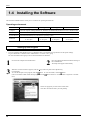
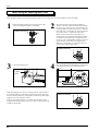
1
3
Switch on the computer and start Windows.
2
Place the CD from the Roland Software Package in
the CD-ROM drive.
The Setup menu appears automatically.
When the screen shown below appears, click the
in [Click here], then choose [EGX-300].
Click [Install].
button. To view the manual, click the button.
To view the description of a program, click the
(There are manuals in PDF format for the programs that the button references. Acrobat Reader is required to view PDF
files.)
If there are programs you don't want to install, then
clear their check boxes before you click [Install].
16
Part 1
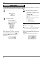
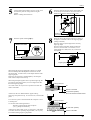
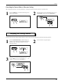
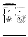
4
The Setup program starts. Follow the messages to carry
out setup and finish setting up the program.
5
If the following screen appears while installing the
driver, click the drop-down arrow and choose the port
for the cable connected to the computer.
7
When all installation finishes, the screen show below
appears.
Click [Close].
9
Remove the CD-ROM from the CD-ROM drive.
*
When using an RS-232C (serial) cable
[COM1:] or [COM2:]
When using a printer (parallel) cable
[LPT1:] or [LPT2:]
When the setup for one program finishes, the
setup for the next program starts.
In the interval until the next setup starts, a dialog
box showing the progress of processing is
displayed.
6
The driver settings appear.
When you make the settings for the communication
parameters of EGX-300, make the parameters match the
values displayed here.
Click [Close] to finish installing the driver.
8
After returning to the menu screen for installation, click
.
17
Part 1
How to use Help
If you have trouble using the program or driver, see the help screens. Help contains information such as descriptions of software operation, explanations of commands, and tips for using the software more effectively.
1
From the [Help] menu, click [Contents].
3
Clicking on an image area that contains an explanation displays the explanation.
2
Clicking on text that is green and underlined (by a
solid or dotted line) displays an explanation.
Tip
When the pointer moves over green underlined text, it
changes to a pointing hand ( ).
When the pointer moves over a location where an explanation is included, it changes to a pointing hand ( ).
When there's a [?] button on screen
Clicking [?] in the upper-right corner of the window makes
). You
the mouse pointer change to a question mark (
can then move the
pointer over any item you wish to
leam more about, then click on the item to display an
explanation of it.
18
When there's a [Help] button on
screen.
Clicking [Help] lets you view help for the window or
software.
Part 1
1-5 Setting the Connection Parameters
Connection with a parallel cable is called a “parallel connection,” and connection with a serial cable is called a “serial connection.” Make
the appropriate settings on both the computer and the EGX-300 to configure the equipment for the type of connection that has been
made. Normally, the setting on the EGX-300 should be made to match the setting on the computer. The steps below describe how to set
connection parameters on the EGX-300. To make the settings on the computer, refer to the manual for the computer or the software in
use.
1
Press the [MENU] key to make the following screen
appear on the display.
2
Press the [ ] key to move the blinking cursor (“ ”) to
“I/O,” and then press the [ENTER] key.
3
Press the [ ] key to move the blinking cursor (“ ”) to
“AUTO,” and then press the [ENTER] key.
4
Press the [MENU] key once.
Make the settings for stop bit, then press the [ENTER] key.
For serial connection only
5
Press the [MENU] key once.
Press the Make the settings for data bits, then press
the [ENTER] key.
6
For serial connection only
7
Press the [MENU] key once.
Make the settings for baud rate, then press the
[ENTER] key.
For serial connection only
Press the [MENU] key once.
Make the settings for parity check, then press the
[ENTER] key.
For serial connection only
8
Press the [MENU] key once.
Make the settings for handshake, then press the
[ENTER] key.
For serial connection only
19
Part 1
1-6 Loading a Workpiece for Cutting
NOTICE
Fasten the tool and material securely in place.
To load workpiece, use the adhesive sheet or clamps included with the machine.
When performing engraving that subjects the workpiece to a load, use the clamps to secure the workpiece in place. When engraving the
edge of the workpiece, use the adhesive sheet.
Large-size material (i.e., material that is about the same size as the EGX-300's table) cannot be affixed to the table securely using the
adhesive sheet or clamps. In such cases, use commercially available double-sided tape to secure the workpiece in place.
A vacuum table (ZV-23A) and a center vise (ZV-23C) are optionally available and should be purchased if needed.
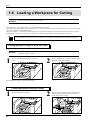
Loading Workpiece Using the Adhesive Sheet
NOTICE
1
Do not attempt to wash the adhesive sheet with water. Doing so will damage the adhesive surface and make it
impossible to grip the material.
Place the adhesive sheet on the table and press it
down.
2
Place the workpiece to be cut on the adhesive sheet
and fasten it while pressing down.
Adhesive
sheet
Workpiece
Adhesive
sheet
Store the adhesive sheet in a location free from dust.
Loading Workpiece Using the Clamps
1
Place the workpiece on the table.
2
Slide the square portion protruding from the bottom
of the clamp plate into the groove on the table to
secure the workpiece in place.
Clamp
Wrenches
(10 mm end
of the wrench)
Tighten
Workpiece
Workpiece
20
Groove
Part 1
Loading Workpiece Using Commercially Double-sided Tape
Apply the double-sided tape to the bottom of the workpiece and secure it to the table.
Double-sided
tape
Workpiece
1-7 Loading a Cutter
Installing the Cutter holder and Collet
NOTICE
To install an end mill using the optionally available collet set (ZC-23), detach the blade holder. If you try to
perform machining with the blade holder installed, the vibration may make it come loose and fall off.
Be sure to use the wrench included with the unit. Using a wrench other than the included one may result in
overtightening, making it impossible to remove the collet or damaging the spindle.
Install a blade holder and collet that match the tool used.
When passing the tool through the holes in the cutter holder and
collet, the combination is suitable if it fits perfectly into the
hole.
Install the cutter holder and collet for the cutter to be used.
Head
Cutter holder
Wrench
(21 mm end of
the wrench)
Collet
Wrench
(10 mm end of the wrench)
21
Part 1
When Using the Depth regulator nose
Using the depth regulator nose makes it possible to engrave even workpiece of non-uniform thickness at the same depth.
1
Rotate than depth regulator nose in the direction of the
arrow 2 in the figure to tighten it completely.
Bottom of the head
2
2
1
This determines the engraving depth (cutting-in
amount). The scale on the micrometer dial assembly
has 25 grooves, with one groove corresponding to an
engraving depth of 0.0254 mm (0.001 in.). (One full
turn of the scale corresponds to an engraving depth of
0.635 mm (0.025 in.).) Rotate the scale in the
direction of the arrow shown in the figure by an
amount equal to or greater than the engraving depth.
For example, when engraving to a depth of 0.5 mm
(0.0197 in.), the scale should be rotated by 20 grooves
(approximately one full turn). For engraving at a
depth of 1.5 mm (0.0591 in.), rotate the scale by 59
grooves (approximately three turns).
Bottom of the head
3
Loosen the Z adjust screw.
4
Press the arrow keys and the [-Z] key to move the tip
of the depth regulator nose to the surface of the
workpiece.
Bottom of the head
Z adjust
screw
Surface of the
workpiece
Table
If the depth regulator nose does not reach the surface of the workpiece
even when the [-Z] key is held down, rotate the micrometer dial in the
direction shown by the arrow in the figure to extent the tip of the depth
regulator nose to the workpiece surface.
If the tip of the depth regulator nose doesn't reach the surface of the
workpiece because the workpiece is too thin, place a board between the
workpiece and the table.
22
Bottom of the head
Part 1
5
Use the height setting made in step 4 to set Z0. Z0 is
the reference point for raising and lowering the
spindle.
Refer to “Setting the Z0 Position.”
6
Insert the cutter into the hole in the cutter holder, and
use the hexagonal screwdriver that comes with the
machine to tighten the cutter mounting screw.
Head
Surface of
the workpiece
7
Raise the spindle with the [+Z] key.
Bottom of the head
8
Rotate the dial in the direction of the arrow shown in
the figure to extend the cutter to the engraving depth
(cutting-in amount).
Move the cutter out just enough for the necessary
engraving depth.
The lines printed on the dial indicate 0.0254 mm
(0.001 in.) for each mark. For instance, to set a
cutting depth of 0.5 mm (0.0197 in.), rotate an 20
mark portion.
Bottom of the head
Surface of
the workpiece
Engraving depth
When setting the engraving depth with software, set a depth
about 2 mm deeper than the depth that would be set on the
micrometer dial. (In other words, 2 mm deeper than the actual
engraving depth.)
Engraving can be done at a standard depth by increasing the
force on the workpiece from the top.
When using the depth regulator nose to perform engraving, the
Z1 point (the tool-down position) is set to a height lower than
the actual engraving depth.
As a result of this, Z1 may be set to a position lower than the
surface of the table.
Cutting-in amount
Z0
Workpiece thickness
Surface of the table
Table
At this time, the error "Bad Parameter" appears during
engraving, and operation stops. To clear the error, switch off the
power.
To avoid errors, place a flat board under the workpiece to serve
as a lifting base.
Use a board of the following thickness.
Thickness of board placed under workpiece
> [Z1] - [Workpiece thickness]
A thickness of about 5 mm (0.2 in.) is appropriate. If the board
is too thick, the Z-axis operating range (30 mm (1.18 in.)) may
be exceeded, making engraving impossible.
Z1 (tool-down position)
Do not set lower than table surface
;;;
;;;
Cutting-in amount
Z0
Workpiece
Lifting-base material
Z1 (tool-down position)
Surface of the table
Table
23
Part 1
When Not Using the Depth regulator nose
If you do not use the depth regulator nose, take a table workpiece made of ABS plastic about 10 mm (1/2 in.) thick,
secure it in place on the included table, and perform surface leveling. By using this as the table surface, you can carry
out engraving at a uniform depth.
1
Loosen the Z adjust screw.
Z adjust screw
2
Press the arrow keys and the [-Z] key to move the tip
of the head to a position close to the surface of the
workpiece.
Bottom of the head
Surface of
the workpiece
3
Insert the cutter into the hole in the cutter holder and
position the tip so that it gently touches the surface of the
workpiece. Use the hexagonal screwdriver that comes
with the machine to tighten the cutter mounting screw.
Head
Surface of
the workpiece
24
4
Use the operation panel to set Z0.
Refer to “Setting the Z0 Position.”
Part 1
Setting the Z0 Position
"Z0" is the origin point for the Z axis. This is normally set at a position which corresponds to the surface of the secured workpiece when
mounting the cutter.
1
Press the [MENU] key to make the following screen
appear on the display.
2
Press the [ENTER] key to make the following screen
appear on the display.
3
Press the [ ] key to move the blinking cursor (“ ”) to
“Z-Axis,” then press the [ENTER] key.
4
Make sure the blinking cursor is on "Z0" and press
the [ENTER] key.
5
Make sure the blinking cursor is on "Y" and press the
[ENTER] key.
6
Selecting "Y" displays the following message.
Selecting "N" returns to the coordinate display (the
screen shown in step 1).
Make sure that “< >” appers.
25
Part 1
1-8 Vacuum Cleaner Connection
Use a commercially available brush
to remove metal cuttings.
Attempting to use a
vacuum cleaner to take
up metal cuttings may
cause fire in thevacuum
cleaner.
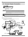
NOTICE
Use a vacuum cleaner that lets you adjust the amount of suction and is equipped with an overload protector.
Always allow a minimum gap of 30 cm (11-13/16 in.) on the side where the vacuum hose exits. The vacuum
hose must have sufficient space in which to move. When the vacuum hose cannot move smoothly, it can cause
malfunctions or errors in operation.
When the fitting diameters do not match or when the vacuum duct cannot be inserted into the suction opening of the
vacuum cleaner, use strong commercial tape (cloth or electrical) to join the fittings.
Vacuum up cutting chips and grit during an on-going cutting operation, using the vacuum adapter, and commercial vacuum cleaner.
Before you install the vacuum adapter
1) Switch on the power and press the [ENTER] key. (The head moves inward and to the left.)
2) Press the [ ] key to move the head leftward and toward the front.
3) Switch off the power.
Commercial
vacuum cleaner
1
Pass the vacuum hose over
the rail to the rear panel of
the unit.
Leave about 20 cm
(about 8 in.) of open
space behind the unit.
Tighten
Vacuum duct
Rail
32 mm (1-5/16 in.)
2
Vacuum
adapter
Attach the vacuum
adapter.
3
Rear
Commercial
vacuum cleaner
26
Secure the vacuum
hose in place.
Tighten
Part 1
1-9 Setting the Origin (Home Position)
The home position is the point that becomes the origin point in the X and Y directions. Usually, this point is set at the front left corner of
the fixed workpiece. The setting method explained here, uses the left, bottom corner (nearest the operator) of the workpiece as the home
position.
* The home position points are registered in the EGX-300 memory right after power is turned on and before power is turned off.
1
Press the [MENU] key to make the following screen
appear on the display.
2
Press the arrow keys and the CUTTER UP/DOWN
keys to move the cutter with the front left corner of
the workpiece.
Bottom of the head
3
Press the [ENTER] key to make the following screen
appear on the display.
4
Press the [ ] key to move the blinking cursor (“ ”) to
“XY-Axis,” then press the [ENTER] key.
5
The display changes to indicate the message shown
below.
Press the [ENTER] key.
6
Make sure the blinking cursor is on "Y" and press the
[ENTER] key.
X axis
7
Y axis
Selecting "Y" displays the following message.
Selecting "N" returns to the coordinate display (the
screen shown in step 1).
Make sure that “< >” appers.
27
Part 1
1-10 Cutting Condition Setting
Before you begin the actual cutting process, the cutting conditions such as the revolution speed of the spindle motor and the feeding
speed of each axis must be designated according to the quality of the workpiece and the type of cutter used. There are several deciding
factors to be taken into account when designating the cutting conditions.
1. The quality of the workpiece
2. The type of cutter used
3. The diameter of the cutter used
4. The cutting method
5. The cutting shape
Designate the cutting conditions in consideration of the above factors by performing the following three EGX-300 setting operations.
1. The spindle motor revolution speed (cutter revolution speed)
2. The feeding speed (cutter moving speed)
3. The cutting-in amount (depth of one cutting operation)
Note : When settings have been made with both the software and the EGX-300, the last settings made have priority.
In this manual, these three conditions are called the cutting conditions. The characteristics and points to consider for each of these
conditions are as follows.
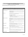
Item
Characteristics/Points to Consider
Spindle motor
revolution speed
The bigger this number, the faster the cutting speed. However, if this number is too large, the work
surface may melt or burn due to excessive friction. Conversely, if this number is made smaller, the time
taken for cutting becomes too longer. Generally speaking, the entire cutting speed is determined by the
cutting edge speed, so the smaller the tool diameter, the higher the spindle revolution speed required.
(When performing engraving without rotating the cutting tool, set “REVOLUTION” to “OFF.”)
Revolution speed : 5,000 to 15,000 rpm
Feeding speed
Cutting-in amount
When the feeding speed is high, processing becomes rough and flash marks tend to remain on the cut
surface. On the other hand, when the feeding speed is slow, processing takes more time.
Be careful because a slower feeding speed does not always result in improved finishing.
When the cutting-in amount is deeper, the cutting speed increases, but the cutting-in amount is limited
by the quality of the workpiece. In cases where the required depth can not be cut at once, repeat cutting
several times to depth that does not breach the limit.
Manual Setting of Cutting Conditions
The cutting conditions can be set manually according to the method described below.
If the cutting conditions can be set with your current software, this is a faster and more efficient method than manual setting. It makes no
difference when you come to construct a program. The following method is appropriate for making delicate halfway adjustments to
conditions previously set using software, etc.
Feeding Speed
1
28
Press the [MENU] key to make the following screen
appear on the display.
2
Press the [ ] or [ ] key to move the blinking cursor
(" ") to the value for the X-Y axes. To set the
machining speed of the head, move the blinking
cursor (" ") to the value for the Z axis.
Part 1
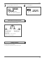
3
4
Press the [ ] or [ ] key to set the feed rate.
Setting range
Press the [ENTER] key.
Make sure that “< >” appears.
X- and Y-axis : 0.5 to 60 mm/sec
Z-axis
: 0.5 to 30 mm/sec
Spindle Motor Revolution Speed
Rotate the spindle control to set the speed of rotation.
LOW
HIGH
5,000 rpm
15,000 rpm
When engraving work
piece material such as
acrylics that weakens
under heat high.
Setting range:
When engraving work
piece material such as
aluminum or brass.
5,000 to 15,000 rpm
* RPM : Revolutions Per Minute
Cutting-in Amount
The cutting-in amount is set by setting Z1.
"1-11 Setting the Z1 and Z2 Position" means to set the Z1 point.
29
Part 1
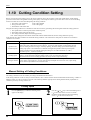
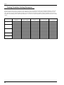
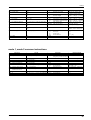
Cutting Condition Setting Examples
The chart below contains reference examples of the appropriate cutting conditions for several types of workpiece material. In the case
that the conditions are input using software or when constructing your own programs, set the cutting conditions with reference to the
chart. However, because conditions differ depending on cutter sharpness and workpiece hardness, cutting performance may not always
be optimal when adhering to the conditions specified below. In such a case, delicate adjustment should be performed at the time of actual
cutting.
Workpiece
Cutter
Spindle revolution
Cutting-in amount
XY axis feeding
Z axis feeding
(Option)
speed (RPM)
(mm)
speed (mm/sec.)
speed (mm/sec.)
Acrylic resin
ZEC-A4025
10000
0.2
15
5
ZEC-A4380
10000
0.2
15
5
Aluminum
ZEC-A4025-BAL
12000
0.05
5
1
ZDC-A2000
Without rotation
0.1
10
1
ZDC-A4000
Without rotation
0.1
10
1
ZEC-A4025-BAL
12000
0.05
5
1
ZDC-A2000
Without rotation
0.1
10
1
ZDC-A4000
Without rotation
0.1
10
1
ZEC-A4025
10000
0.4
30
10
Brass
Chemical wood
ZEC-A4380
10000
0.5
30
5
Modeling wax
ZEC-A4025
10000
0.5
30
10
(Option)
ZHS-A4380
10000
0.8
30
5
30
Part 1
1-11 Setting the Z1 and Z2 Position
The cutter up position (Z2 point) and down position (Z1 point)
are normally set with the software. If they cannot be set with
your current software then set them manually using the keys on
the switch panel.
* The Z0, Z1, and Z2 points can be stored in memory by setting
“Z0/Z1/Z2 MEMORY” to “ON.”
Cutter
Cutter up positon
Z2
Z0
Cutter down positon Z1
Workpiece
1
Press the [MENU] key to make the following screen
appear on the display.
2
Press the [ENTER] key to make the following screen
appear on the display.
3
Press the [ ] key to move the blinking cursor (“ ”)
to “Z-Axis,” then press the [ENTER] key.
4
Press the [ ] key to move the blinking cursor (“ ”) to
“Z1.”
When setting the Z2 point, press the [ ] key to move
the blinking cursor (“ ”) to “Z2.”
5
Press the arrow keys and the CUTTER UP/DOWN
keys to move the cutter to the height where Z1 (or Z2)
point is to be set.
When setting Z1, move the cutter to a position away
from the loaded workpiece.
6
Make sure the blinking cursor is on "Z1" and press
the [ENTER] key.
Bottom of the head
Z2
Z0
Z1
31
Part 1
7
Make sure the blinking cursor is on "Y" and press the
[ENTER] key.
8
Selecting "Y" displays the following message.
Selecting "N" returns to the coordinate display (the
screen shown in step 1).
Make sure that “< >” appears.
1-12 Sending Cutting Data
NOTICE
Do not operate beyond capacity or subject the tool to undue force.
The tool may break. If machining operation beyond capacity is started inadvertently, immediately press the
EMERGENCY STOP switch.
If the cover must be opened during cutting, first press the [ENTER/PAUSE] key to pause the EGX-300, then
open the cover. After the cover has been closed, cutting resumes when the paused state is canceled.
(The spindle will not rotate while the cover is open.)
The EGX-300 performs cutting after receiving cutting data from the computer (application).
Data may be output, for example, after it has been created using any of a number of applications, or from driver.
In this section, general matters related to data output are explained. Refer to this section when carrying out data output. For details of the
cutting data output method, refer to the operation manual for the application software or driver used.
Setting the Output device
Please select from among the models shown below when making the settings for output device with the application software.
Output
model
Instruction
system
Command setting
on the EGX-300
Coordinate unit setting
on the EGX-300
EGX-300
CAMM-GL I
AUTO
0.01 mm
PNC-2300A
CAMM-GL I
AUTO
0.01 mm
CAMM-2 Series
CAMM-GL II
AUTO
0.01 mm
CAMM-3 Series
CAMM-GL I
AUTO
0.01 mm
* When set to “AUTO,” the machine automatically determines whether the mode 1 or mode 2 instruction system is used.
32
Part 1
1-13 Finishing
Do not carelessly insert the hands
while in operation.
Please use a vacuum cleaner to
remove cutting dust.
Do not use any blower like airbrush.
Doing so may result in injury (during manual
operation.).
Otherwise, dust spread in the air may harm
your health or damage this machine.
Perform dry cutting with no cutting
oil.
Such materials can
cause fire.
When you're finished,
wash your hands to
rinse away all
cuttings.
Use a commercially available brush
to remove metal cuttings.
Attempting to use a
vacuum cleaner to take
up metal cuttings may
cause fire in thevacuum
cleaner.
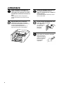
After cutting has been finished, detach the cutter, remove the workpiece, and clean away chips.
1
Press the [MENU] key to make the following screen
appear on the display.
2
Press the arrow keys and the [+Z] key to move the
bed to a position where the cutter and material can
easily be detached.
33
Part 1
3
Open the cover and detach the cutter.
Head
4
Remove the workpiece.
If the material has been secured in place using an
adhesive sheet or double-sided tape, peel it off of the
bed.
5
34
Use a commercially available vacuum cleaner to
remove chips inside the box.
Part 2
Part 2 User's Reference
2-1 Cutting Area
The maximum cutting area of the EGX-300 is 305 mm (X) x 230 mm (Y) x 30 mm (Z) (12 in. (X) x 9 in. (Y) x 1-1/8 in. (Z) ). When
converted to coordinate values, this corresponds to (x, y, z) = (30500, 23000, 3000) when the coordinate unit is 0.01 mm, or (x, y, z) =
(12200, 9200, 3000) when the coordinate unit is 0.025 mm. Changing the coordinate unit causes only the coordinate units for the X and
Y axes to change. The coordinate unit along the Z axis is always 0.01 mm/step.
The actual available cutting area is subject to restrictions according to the length of the attached cutter and the workpiece height; and in
some cases it may be larger than the maximum operating area.
+Z
30 mm
(1-1/8 in.)
+Y
+X
305 mm
(12 in.)
230 mm (9 in.)
35
Part 2
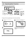
2-2 Operating Each Function
Making Settings with the Liquid-crystal Display
When coordinate values are displayed:
Use the
and
keys to move along the X axis.
Use the
and
keys to move along the Y axis.
Use the
and
keys to move along the Z axis.
Use the
and
keys to move the blinking
cursor (“ ”) and select the execution item.
Press the
key to execute.
Press the
and
keys to move the blinking
cursor (“ ”) and select the
setting item.
Press the
and
keys
to move the blinking cursor (“ ”)
and select the setting item.
Press the
key to confirm.
Press the
key to
display the next menu.
Press the
and
keys to change the value (or
selection choice), and then
press the
key to confirm.
Press the
and
keys
to move the blinking cursor (“ ”)
and select the setting item.
Press the
key to confirm.
The value (or selection
choice) enclosed in angled
brackets (“< >”) indicates
the current setting.
Changing to Other-language Messages on the Liquid-crystal Display
1
Switch on the power while holding down the
[MENU] key.
While pressing
the [MENU] key.
2
Press the [ ] key to move the blinking cursor (“ ”) to
“Japanese,” and then press the [ENTER] key.
Turn the power on
+
3
36
Messages on the display now appear in Japanese.
* To return the display to English-language messages,
carry out Step 1 again. When the language-selection
menu appears (similar to the one in Step 1, but in
Japanese), move the cursor to “
” and press the
[ENTER] key.
Part 2
Performing Repeat Cutting
The data buffer is the place where data received from the computer is stored temporarily. (The data in the data buffer can be erased by
switching off the power or executing the “CLEAR”.)
Executing the “REPEAT” calls up the cutting data stored in the EGX-300's data buffer and executes the replotting procedure.
When replotting is executed, the entire data content of the data buffer is called up. When you perform replotting, clear the data from the
data buffer before sending the cutting for replotting from the computer.
1
Press the [MENU] key to make the following screen
appear on the display.
2
Press the [ ] key to move the blinking cursor (“ ”) to
“CLEAR,” then hold down the [ENTER] key for 0.5
sec or more. This makes “CLEAR” start to flash.
3
Install the cutter and load the material.
After closing the cover, use the software to send
cutting data.
4
After cutting has finished, remove the cut material
and load a new piece. Set the origin point if necessary.
5
Press the [MENU] key to make the following screen
appear on the display.
6
Press the [ ] key to move the blinking cursor (“ ”) to
“REPEAT,” and then press the [ENTER] key.
37
Part 2
Changing the Feed Rate or Spindle Speed During Cutting
The feed rate and spindle rotating speed set by the software can be changed while cutting is in progress.
This is done by first pausing the EGX-300 during cutting, then changing the feed rate. However, if the computer subsequently sends a
command to change the feed rate, the setting will change as specified by the new command. When set by software or set directly on the
EGX-300, the setting made last takes precedence.
Spindle speed can be changed at any time. Use the Spindle control to change it.
Changing the Feed Rate
1
Press the [ENTER/PAUSE] key while cutting is in
progress. One cutting step is performed, after which
operation stops. The display changes to show the
following message.
2
Press the [MENU] key to make the following screen
appear on the display.
3
Press the [ ] or [ ] key to move the blinking cursor
(“ ”) to “XY-SPEED.”
To set the lowering speed of the head, move the
blinking cursor (“ ”) to “Z-SPEED.”
4
Press the [ ] or [ ] key to set the feed rate.
Setting range
X- and Y-axis : 0.5 to 60 mm/sec
Z-axis
: 0.5 to 30 mm/sec
5
Press the [ENTER] key.
Make sure that
“< >” apears.
38
Part 2
Canceling the Paused State to Resume Cutting
After changing the feed rate, cancel the paused state. Cutting then resumes at the new feed rate or spindle speed.
1
Press the [MENU] key to make the following screen
appear on the display.
2
Press the [ ] key to move the blinking cursor (“ ”) to
“CONTINUE,” and then press the [ENTER] key.
Stopping the Cutting Process
In the case that you begin cutting and then find that you have sent the wrong cutting data, perform the following operation.
1
Press the [ENTER/PAUSE] key while cutting is in
progress. One cutting step is performed, after which
operation stops. The display changes to show the
following message.
3
Press the [ ] key to move the blinking cursor (“ ”) to
“STOP,” and then press the [ENTER] key.
2
Use the software to stop data output.
39
Part 2
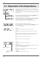
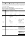
2-3 Explanation of the Display Menus
This shows the current position of the cutter (in coordinates). The coordinate values
indicate the home position as the origin point on the X and Y axes, and the Z0 point as the
origin point on the Z axis.
It is possible to move from this menu to submenus for setting the X- and Y-axis origin
point (home position), the Z-axis origin point (Z0), the cutter-up position (Z2), the cutter
down position (Z1).
This sets the X- and Y-axis origin point (home position). Use the arrow keys to move the
cutter to the desired location for the home position, and press the [ENTER] key.
For details, see “Setting the Origin (Home Position)”.
This sets the Z-axis origin point (Z0), cutter-up position (Z2), and cutter down position
(Z1). Move the blinking cursor (“ ”) on the display to “Z0,” “Z1,” or “Z2,” align the tip
of the cutter to the height to be set, then press the [ENTER] key.
For details, see “Setting the Z0 Position” or “Setting the Z1 and Z2 Position”.
This shows the X/Y-axis feed rate and the Z-axis feed rate.
Move the blinking cursor (" ") on the display to the value for the X-Y axes or for the Z
axis, use the [ ] or [ ] key to set the feed rate, then press the [ENTER] key.
For details, see “Feeding Speed”.
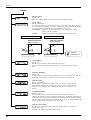
“HOME”
This moves the cutter to the current home position (XY origin point).
“VIEW”
This raises the cutter to its highest point and moves the XY table to the front left.
“Z1”
This starts the spindle motor and moves the cutter to the current cutter-down position.
Spindle rotation and cutter changing do not take place while the cover is open.
“Z0”
This moves the cutter to the current Z-axis origin point.
“Z2”
This moves the cutter to the current cutter-up position.
“CLEAR”
This deletes any cutting data stored in the data buffer.
“REPEAT”
This loads cutting data that is stored in the data buffer and performs cutting. This makes
it possible to cut multiple copies of the same shape.
For details, see “Performing Repeat Cutting”.
Go to the submenus for
“I/O”.
Go to the submenus for
“OTHERS”.
40
“I/O”
This changes to the menu for the connection interface and setting communication
parameters for serial communication.
“OTHERS”
This changes to the menu for making other settings.
Part 2
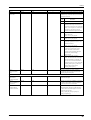
I/O
“I/O”
Default : AUTO
This sets the type of interface connected to the computer. When set to “AUTO,” the
interface type (parallel or serial) is determined automatically. However, serial communication parameters (baud rate, parity checking, stop bit, data bit, and handshaking settings)
are not determined and must be set.
“STOP”
Default : 1
This sets the number of stop bits when using a serial connection. Either 1 bit or 2 bits can
be selected.
“DATA”
Default : 8
This sets the data bit length when using a serial connection. A length of either 7 bits or 8
bits can be selected.
“PARITY”
Default : NONE
This makes the setting for parity checking when using a serial connection. The available
selections are no parity (“NONE”), even parity (“EVEN”), and odd parity (“ODD”).
“BAUDRATE”
Default : 9600
This sets the baud rate when using a serial connection. The available selections are 9600,
and 4800 bps.
“HANDSHAKE”
Default : HARD
This sets the handshaking mode when using a serial connection. Either hardwire (HARD)
handshaking or Xon/Xoff control can be selected.
41
Part 2
OTHERS
“REVOLUTION”
Default : ON
When set to “OFF,” cutting can be performed without rotating the spindle.
“OVER AREA”
Default : CONTINUE
This selects the action when the cutter returns from a coordinate outside the cutting range
to a coordinate inside the range. (The cutter cannot actually be moved outside the cutting
range, but the EGX-300's internal processing handles this as if it had.)
“CONTINUE”: Operation is not paused upon return to the cutting range. Cutting
continues without interruption.
“PAUSE”
: Operation is paused when the cutter returns to the cutting range.
“CONTINUE”
“PAUSE”
Cutting area
(305 mm x 230 mm
(12 in. x 9 in.))
Cutting area
(305 mm x 230 mm
(12 in. x 9 in.))
1
2
Operation contiunes
1
2
Operation is paused
: Tool path
: Coodinate point
“SMOOTHING”
Default : ON
Smoothing is a function for cutting smooth arcs and circles.
This is set to "ON" when shipped from the factory. To disable smoothing, set this to
"OFF".
“Z0/Z1/Z2 MEMORY”
Default : ON
This toggles the Z0, Z1 and Z2 points memory function on or off. When set to “ON,” the
Z0, Z1 and Z2 points remain in memory even after the power is switched off.
“RESOLUTION”
Default : 0.01 mm/step
This selects the unit used for coordinates. Either 0.01 mm/step or 0.025 mm/step
can be selected. Changing the coordinate unit causes only the coordinate units for
the X and Y axes to change. The coordinate unit along the Z axis is always 0.01
mm/step.
“COMMAND MODE”
Default : AUTO
This selects the instruction system for data sent from the computer. When set to
“AUTO,” the instruction system is determined automatically. If automatic determination
is not made correctly, find out what instruction system the application software (or driver)
uses for data that is sent, and change this setting to “1” or “2.” Refer to the manual for the
software to determine the instruction system of sent data.
“REVOLUTION TIME”
This shows the rotation time of the spindle. The spindle rotation time cannot be
returned to “0” (zero).
For details, see “Display of Spindle Rotation Time”.
42
Part 2
2-4 Maintenance
Please use a vacuum cleaner to
remove cutting dust.
Do not use any blower like airbrush.
Otherwise, dust spread in the air may harm
your health or damage this machine.
Use a commercially available brush
to remove metal cuttings.
Before attempting to replace the
motor brushes or the spindle motor,
stop cutting operations on the EGX300 and allow to stand for an hour or
so.
Failure to do so may result in burns from the
hot motor.
Attempting to use a
vacuum cleaner to take
up metal cuttings may
cause fire in thevacuum
cleaner.
NOTICE
When cleaning the EGX-300, make sure that the main unit's power OFF.
When replacing the motor brushes, first touch the table to discharge static electricity from your body.
Failure to follow the procedure for discharging static electricity may result in breakdown.
Cleaning the Main Unit
When the main unit becomes dirty, use a dry cloth to wipe it.
Cleaning Inside the Cover
After cutting work is completed, use a vacuum cleaner to clean the
EGX-300 main unit and the surrounding area of cutting dust.
If a large amount of cutting dust builds up while cutting work is in
progress, then press the [ENTER/PAUSE] key to pause cutting, open
the cover, and clean out any buildup within the unit. When you're
finished cleaning, close the cover and press the [ENTER/PAUSE] key
to resume cutting.
Clean this area as well.
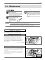
Cleaning the Interior of the Bellows
A large amount of cutting dust may accumulate when end-mill cutting
or the like is performed. After cutting has finished, clean the interior
of the bellows.
Loosen the left-hand and right-hand screws on the head, and move the
bellows to one side. Use a vacuum cleaner to clean the buildup of
cuttings inside the bellows.
Bellows
Bellows
Turn the screw
using the included
hexagonal wrench.
43
Part 2
Replacing the Motor Brushes
The brushes for the spindle motor should be replaced periodically. As a general guide, replacement after every 1,000 hours of spindle
rotation is suggested. For an explanation of how to check the spindle rotation time, see “Display of Spindle Rotation Time” .
The useful life of the motor ends when the replaced motor brushes wear out (after approximately 2000 hours of spindle operation). When
this happens, replace it with a new spindle motor (optionally available).
1
Turn the power OFF.
2
Loosen the screws on the left and right, and remove
the spindle cover.
Head
Spindle cover
Turn the screw using
the included
hexagonal wrench.
3
Use a commercially available flathead screwdriver to
remove the front and rear brush covers.
4
Remove the old motor brush and replace with a new
one.
Remove the brush
cover on the
opposite side as well
Motor brush
5
Reattach the brush covers.
Attach the brush
cover on the
opposite side as well
6
Reattach the spindle cover.
Head
Spindle cover
Maintenance tasks that can be carried out by the user are cleaning of the main unit, cleaning inside the cover,
cleaning inside the bellows, and replacement of the motor brushes. Oil supply and other maintenance are not
required.
44
Part 2
Checking the Spindle Motor
Operate the spindle motor alone, with no cutter installed or material loaded. If the speed of rotation is uneven, or if you hear an unusual
noise, please consult your authorized Roland DG Corp. dealer or service center.
1
Turn the power ON.
2
Display the screen shown below and make sure that
“REVOLUTION” is set to “ON.”
3
Close the cover.
4
Press the [SPINDLE ON/OFF] key to rotate the
spindle.
45
Part 2
Display of Spindle Rotation Time
The EGX-300 has a function for the displaying the total rotation time of the spindle. The service life of the unit can be extended by
carrying out periodic inspection. As a general guide, this inspection should be performed after every 500 hours of use.
1
Press the [MENU] key to make the following screen
appear on the display.
3
Press the [MENU] key to make the following screen
appear on the display.
2
Press the [ ] key to move the blinking cursor (“ ”) to
“OTHERS,” and then press the [ENTER] key.
Check the total rotation time
of the spindle.
Recommended Service Checking
The EGX-300 is a precision machine. In order to maintain it safely for operation over the long term, we recommend that it should be
checked by a qualified serviceman. There is a charge for this service. Please take note of this in advance.
Maintenance to Be Performed by a Service Technician
- Inspection and maintenance at every 500 hours of spindle rotation time (refer to “Display of Spindle Rotation Time”)
- Checking and adjustment of the spindle belt
- Replacement of consumable parts (spindle belt, spindle motor, spindle unit)
46
Part 2
2-5 Troubleshooting
When the EGX-300 does not work...
Is the cover open?
The EGX-300 will not operate when the cover is open. Close the cover
and try again.
Is operation paused?
If the [ENTER/PAUSE] key is pressed while the machine is in operation,
the message “Pause On” appears on the display and operation is paused.
Choose “CONTINUE” and press the [ENTER/PAUSE] key again to
cancel the paused state.
Do the EGX-300's connection parameter settings
match the settings for the computer?
Refer to “Setting the Connection Parameters” to make the correct settings.
Is the power for the EGX-300 switched on?
Make sure the EGX-300 is powered up.
Has the connection cable come loose?
Make sure the connection cable is plugged in securely with no looseness
at either end.
Is the correct connection cable being used?
The type of connection cable varies according to the computer being used.
Also, some application software requires the use of a special cable. Make
sure the correct cable is being used.
Is the correct output device setting (or driver
selection) made for the application software?
Refer to the documentation for the application software to make the
correct output device setting (or driver selection) for the application
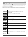
software.
When the spindle does not rotate ...
Is “REVOLUTION” set to “OFF?”
If “REVOLUTION” is set to “OFF,” the spindle will cut without
rotating.
Change the setting for “REVOLUTION” to “ON.”
The power does not come on...
Is the EMERGENCY STOP switch set to STOP
( )?
If the EMERGENCY STOP switch has been depressed, the power will not
come on when the power switch is turned on.
Set the EMERGENCY STOP switch to RELEASE ( ).
Has the power cord come loose?
Make sure the power cord is plugged in securely with no looseness at
either end.
Cutting depth varies in places (deep and shallow cuts)
Is the workpiece flexing?
Check the setting and clamping of the workpiece.
Is the workpiece height uneven because of the
double-sided tape used for securing it was stuck
on poorly?
Check how well the material is secured and reload it.
* Cutting to the same depth, even of workpieces of different thicknesses can be done if the depth regulator nose is used.
47
Part 2
Cutting line varies in places
Is the workpiece vibrating because the adhesive
double sided tape was stuck on poorly?
Check where the double-sided tape is affixed and reload the material.
Engraving cannot be performed at the desired location
Is there a mistake in the home position setting?
Refer to “Setting the Origin (Home Position)”. Use these procedures to
set the home position correctly.
Was there a position error when the workpiece
was replaced?
Check that workpiece position setting is correct.
The letters have been cut too deep (or too shallow) and cannot be read
Is the cutter mounted securely?
Refer to “Loading a Cutter” to install the cutter securely.
Is there a mistake in the Z position?
Increase (or decrease) the “Z1” setting as needed.
When moving the cutter while in the up position the cutter tip contacts or pulls on the workpiece
Is there a mistake in the Z position?
Refer to "Setting the Z1 and Z2 Position”. Increase the “Z2” setting as
needed.
Burrs are present on grooves made during cutting
Is the cutter mounted securely?
Refer to “Loading a Cutter” to install the cutter securely.
Is the tip of the cutter worn?
When the tip of the cutter is worn, replace with a new one.
Is the cutter feed speed too fast (spindle rotation
speed too slow).
Refer to “Feeding Speed” to find the correct feed speed “XY-SPEED”
and “Z-SPEED”, and adjust the spindle rotation speed by referring to
“Spindle Motor Revolution Speed”.
The cutting finish is unsatisfactory
Separating the process of cutting the material into two stages makes for engraved results which are more attractive. After rouging out the
general shape with “rough engraving,” “finishing” is performed to produce the final results.
For instance, to cut letters to a depth of 0.3 mm, first of all rough cut to a depth of 0.25 mm. Then continue exactly the same kind of
cutting to a depth of 0.3 mm.
48
Part 2
2-6 Error Messages
An error message will appear if incoming data has any of the errors listed in table. Since the error is shown in the display for informational purposes, the data transfer continues and you are allowed to perform the next operation.
To get the error message to go away, press the [MENU] key.
Note that even though the error message is no longer displayed after you press the [MENU] key, the EGX-300 will retain in memory the
fact that the error occurred. To clear the error, switch the power off and back on. Occurrence of an error may make correct engraving
impossible.
Error message
Meaning
Appears if an instruction that the EGX-300 cannot interpret is sent. This error is generated if an
instruction from the “mode2” set is sent when the unit has been set to recognize “mode1,” or
viceversa. Change the setting for the recognized instruction set, using the control panel, and this error
should no longer occur.
Appears if the number of parameters differs from the permissible number.
Appears if the value specified for a parameter is out of the permissible range.
Appears if an unusable character is specified.
Appears if the polygon buffer is full.
Appears if an output instruction is sent from the computer during execution of a previous output
instruction. More precisely, there is a certain amount of delay between the moment an output
instruction is given and the instant actual output begins. This error message appears if the new output
request arrives during this delay time. (The delay time can be set using the [ESC].M instruction.)
Appears if a device control instruction that the EGX-300 cannot interpret is sent.
Appears if an invalid parameter has been specified for a device control instruction.
Appears if the value for a device control instruction parameter exceeds the permissible limit.
Appears if the number of parameters for a device control instruction is more than that permissible.
Appears if a framing error, parity error, or overrun error occurs at the time of data reception. (There is
a problem with one of these settings: Baud Rate, Parity, Stop Bits, or Data Bits. The protocol settings
for the EGX-300 must be made correctly in order to match the settings your computer is set to use.)
Appears if the I/O buffer has overflowed. (There is a problem with the connecting cable, or the
settings for Handshaking. Make sure you are using a cable appropriate for the computer being used.
Also, check that the setting for Handshaking is correct.)
Appears if an indeterminate communication error other than the I/O errors described above has
occurred.
49
Part 2
2-7 Other Messages
Besides error messages related to commands or communication parameters, the following messages may also appear on the display.
Message
Meaning
This message appears if repeat cutting is attempted when the cutting data exceeds 1 MB. The data
cannot all fit in the EGX-300's data buffer, so repeat cutting cannot be performed.
This message appears if cutting is attempted while the cover is open.
This message appears if repeat cutting is attempted when the data buffer is empty. Send cutting data
before performing repeat cutting.
The EGX-300 stops automatically if an excessive load is placed on the spindle during cutting. The
message shown at left appears at this time. The overload may be due to excessive hardness of the
material, an excessive amount of cutting, or a feed rate that is too fast. Investigate the problem and
eliminate the cause of the overload.
The message at left also appears when the motor brushes have worn out or the useful life of the motor
has ended. When this happens, refer to "Checking the Spindle Motor" and operate the spindle alone,
with no cutter installed or material loaded. If the spindle does not rotate, the motor brushes are worn
out or the motor has reached the end of its useful life.
If the motor brushes now installed in the motor have not been replaced, it means the motor brushes
are worn out. Replace with new motor brushes (see "Replacing the Motor Brushes").
The useful life of the motor ends when the replaced motor brushes wear out (after approximately
2000 hours of spindle operation). When this happens, replace it with a new spindle motor (optionally
available).
The error can be cancelled by switching the power to the unit off and then on again.
When the power is switched on, a message may be displayed indicating that buildup of cuttings has
obstructed movement of the head.
Clean away all cuttings from around the table.
Switch the power off and back on again to cancel the error.
This message may be displayed when the material is too hard to be cut.
Switch the power off and back on again to cancel the error. When using with the Z adjust screw
released (such as when using the depth-regulator nose), tighten the screw before switching the power
on again.
50
Part 2
2-8 List of CAMM-GL I Instructions
A “CAMM-GL I Programmer's Manual” is available for separate purchase for those wishing to create their own programs for this
machine. For further information, please contact the nearest Roland DG Corp. dealer or distributor.
*1: -(226-1) to +(226-1)
*2: 0 to +(226-1)
*3: -(226-1)° to +(226-1)°
mode 1
Instruction
@ Input Z1 & Z2
@ Z1, Z2
H
D
M
I
R
L
B
X
Home
Draw
Move
Relative Draw
Relative Move
Line Type
Line Scale
Axis
H
D x1, y1, x2, y2, ...... , xn, yn
M x1, y1, x2, y2, ...... , xn, yn
I ∆x1, ∆y1, ∆x2, ∆y2, ...... , ∆xn, ∆yn
R ∆x1, ∆y1, ∆x2, ∆y2, ...... , ∆xn, ∆yn
Lp
Bl
X p, q, r
P
S
Q
N
U
C
Print
Alpha Scale
Alpha Rotate
Mark
User
Circle
P c1c2......cn
Sn
Qn
Nn
Un
C x, y, r, q1, q2 (, qd)
E
Relative Circle
Er, q1, q2 (, qd)
A
G
Circle Center
A + Circle
A x, y
G r, q1, q2 (, qd)
K
A+%
K n, l1, l2
T
Hatching
T n, x, y, d, t
V
F
Z
Velocity Z-axis
Velocity X,Y-axis
XYZ Axis
Simultaneous Feed
O Output Coordinate
W Dwell
!
^ Call mode2
Format
Vf
Ff
Z x1, y1, z1, ..... , xn, yn, zn
O
Wt
!n
^ [mode2] [parameter] ...... [parameter] [;]
Z1
Z2
None
xn, yn
xn, yn
∆xn, ∆yn
∆xn, ∆yn
p
l
p
q
r
cn
n
n
n
n
x, y
r
q1
q2
qd
r
q1
q2
qd
x, y
r
q1
q2
qd
n
l1
l2
n
x, y
d
t
f
f
xn, yn
zn
None
t
n
Parameter
Position on Z1
Position on Z2
Range [Default]
-3000 to 0 [0]
0 to +3000 [0]
Absolute coordinate
Absolute coordinate
Relative coordinate
Relative coordinate
Line pattern
Pitch length
Coordinate axis
Tick interval
Repeat number
Character string
Character size
Rotation angle
Number of special symbol
*1
*1
*1
*1
-5 to +5 [Solid line]
* 2 [1.5% of (P2-P1)]
0, 1
*1
1 to 32767
Center coordinate
Radius
Start angle
Completion angle
Resolution
Radius
Start angle
Completion angle
Resolution
Center coordinate
Radius
Start angle
Completion angle
Resolution
Angle of segment line
Length to end of segment line
Length to beginning of
segment line
Hatching pattern
Length of rectangle side
Intervals between hatching lines
Hatching angle
Feed rate for Z axis
Feed rate for X and Y axis
XY coordinate
Z coordinate
0 to 127 [3]
0 to 3 [0]
1 to 15
1 or 2 [1]
*1
*1
*3
*3
* 3 [5°]
*1
*3
*3
* 3 [5°]
* 1 [x=0, y=0]
*1
*3
*3
* 3 [5°]
*1
*1
*1
0 to 3
*1
*1
1 to 4
0 to 30 [mm/sec] [2 [mm/sec]]
0 to 60 [mm/sec] [2 [mm/sec]]
*1
*1
Dwell time
0 to 32767 [msec] [0 [msec]]
Turns or stops the spindle motor -32767 to +32767 [0]
51
Part 2
mode 2
Instruction
AA Arc Absolute
Format
AA x, y, qc (, qd);
AR Arc Relative
AA ∆x, ∆y, qc (, qd);
CA Alternate Character Set
CA n;
CA
CI r (, qd) ;
CI
Circle
CP Character Plot
CS Standard Character Set
DF Default
DI Absolute Direction
DR Relative Direction
DT
EA
ER
EW
Defined Label Terminator
Edge Rectangle Absolute
Edge Rectangle Relative
Edge Wedge
FT
Fill Type
IM Input Mask
IN
IP
Initialize
Input P1 & P2
CP nx, ny ;
CP ;
CS n;
CS ;
DF ;
DI run, rise ;
DI ;
DR run, rise ;
DR ;
DT t ;
EA x, y ;
ER ∆x, ∆y ;
EW r, q1, qc (, qd) ;
FT n (, d (,q)) ;
FT ;
IM e ;
IM ;
IN ;
IP P1x, P1y (, P2x, P2y) ;
x, y
qc
qd
∆x, ∆y
qc
qd
n
r
qd
nx, ny
n
None
run
rise
run
rise
t
x, y
∆x, ∆y
r
q1
qc
qd
n
d
q
e
None
P1x, P1y
P2x, P2y
LLx, LLy
URx, URy
cn
n
l
None
None
None
None
None
None
None
None
None
None
xn, yn
Parameter
Center coordinate
Center angle
Chord tolerance
Center coordinate
Center angle
Chord tolerance
Character set No.
Range [Default]
*1
*3
* 1 [5°]
*1
*3
* 1 [5°]
0 to 59, 99 [0]
Radius
Chord tolerance
Number of character
in X or Y-axis direction
Character set No.
*1
* 3 [5°]
*1
*1
0 to 59, 99
X-axis direction vector
Y-axis direction vector
X-axis direction vector
Y-axis direction vector
Label terminator
Absolute coordinates of rectangle
Relative coordinates of rectangle
Radius
Start angle
Center angle
Chord tolerance
Pattern
Spacing
Angle
Error mask value
-128 to +128 [1]
-128 to +128 [0]
-128 to +128 [1]
-128 to +128 [0]
[ [ETX] (03h) ]
*1
*1
*1
*3
*3
* 3 [5°]
1 to 5 [1]
* 2 [1% of (P2x-P1x)]
* 3 [0°]
0 to 255 [223]
XY coordinates of P1
XY coordinates of P2
Lower left coordinates
Upper right coordinates
Character string
Pattern number
1 pitch length
*1
*1
*1
*1
IW Input Window
IW LLx, LLy, URx, URy ;
LB Label
LT Line Type
LB c1c2.....cn [label terminator]
LT n (, l) ;
LT ;
OA ;
OC ;
OE ;
OF ;
OH ;
OI ;
OO ;
OP ;
OS ;
OW ;
PA x1, y1 (, x2, y2......., xn, yn) ;
Absolute XY coordinates
PA ;
PD x1, y1 (, x2, y2......., xn, yn) ;
xn, yn XY coordinates
PD ;
PR ∆x1, ∆y1 (, ∆x2, ∆y2......., ∆xn, ∆yn) ; ∆xn,∆yn Relative XY coordinates
PR ;
PT d ;
d
Tool width (diameter)
PT ;
PU x1, y1 (, x2, y2......., xn, yn) ;
xn, yn XY coordinates
PU ;
Absolute coordinates of rectangle
RA x, y ;
x, y
RR ∆x,∆y ;
∆x,∆y Relative coordinates of rectangle
SA ;
None
SC Xmin, Xmax, Ymin, Ymax ;
Xmin, Ymin User XY coordinates of P1
SC ;
Xmax, Ymax User XY coordinates of P2
SI w. h ;
w
Character width
SI ;
h
Character height
SL tanq;
tanq
Character slant
SL ;
OA
OC
OE
OF
OH
OI
OO
OP
OS
OW
PA
Output Actual Position
Output Commanded Position
Output Error
Output Factor
Output Hard-Clip Limits
Output Identification
Output Option Parameter
Output P1 & P2
Output Status
Output Window
Plot Absolute
PD Pen Down
PR Plot Relative
PT
Pen Thickness
PU Pen Up
RA
RR
SA
SC
Shade Rectangle Absolute
Shade Rectangle Relative
Select Alternate Set
Scaling
SI
Absolute Character Size
SL
Character Slant
52
[0]
0 to 6 [Solid line]
* 2 [%] [1.5 % of (P2-P1)]
*1
*1
*1
0 to 5 [mm]
[ 0.3 [mm] ]
*1
*1
*1
*1
*1
-30 to +30 [cm] [0.19 [cm]]
-30 to +30 [cm] [0.27 [cm]]
* 1 [0]
Part 2
Instruction
SM Symbol Mode
WG Shade Wedge
Format
SM s ;
SM ;
SR w, h ;
SR ;
SS ;
TL lp (, ln) ;
TL ;
UC (c,) ∆x1, ∆y1 (,(c,) ∆x2, ∆y2...∆xn, ∆yn) ;
UC ;
VS s ;
VS ;
WD c1c2 ... cn;
WD;
WG r, q1, qc (, qd) ;
XT X-Tick
YT Y-Tick
XT ;
YT ;
SR Relative Character Size
SS Select Standard
TL Tick Length
UC User Defined Character
VS Velocity Select
WD Write to Display
s
Parameter
Character or symbol
w
h
Character width
Character height
Range [Default]
21h to 3Ah, 3Ch to 7Eh
[Clears symbol mode]
-128 to +128 [%] [0.75 [%]]
-128 to +128 [%] [1.5 [%]]
Tick length in positive direction
Tick length in negative direction
Tool control value
Units of movement
Feed rate for X and Y axis
-128 to +128 [%] [0.5 [%]]
-128 to +128 [%] [0.5 [%]]
-128 to -99, +99 to +128
-99<∆xn, ∆yn<99
0 to 60 [mm/sec] [2 [mm/sec]]
Character
CHR$ (32) to CHR$ (127),
CHR$ (160) to CHR$ (223)
*1
*3
*3
* 3 [5°]
lp
ln
c
∆xn,∆yn
s
cn
r
q1
qc
qd
None
None
Radius
Start angle
Center angle
Chord tolerance
mode 1, mode 2 common instructions
Instruction
!DW Dwell
!IO Input Home Position
Format
!DW t [terminator]
!IO x, y [terminator]
!MC Motor Control
!MC
!MC
!NR
!OZ
!PZ
!NR Not Ready
!OZ Output Z-coordinate
!PZ Set Z1&Z2
!VZ Velocity select Z-axis
!ZM XYZ Axis
Simultaneous Feed
!ZO Set Z0
!ZZ Z
n [terminator]
[terminator]
[terminator]
[terminator]
z1 (, z2) [terminator]
!VZ s [terminator]
!ZM z [terminator]
!ZO z [terminator]
!ZZ x1, y1, z1, ...... , xn, yn, zn [terminator]
t
x, y
n
Parameter
Range [Default]
Dwell time
0 to 32767 [0]
Coordinates of home position * 1
(designate by machine coordinate)
Motor ON/OFF switching
-32768 to 32767 [motor ON]
None
None
z1
z2
s
z
Z1 coordinates
Z2 coordinates
Feed rate (Z axis)
Z coordinate
-3000 to 0 [0]
0 to 3000 [0]
0 to 30 [mm/sec] [2 [mm/sec]]
-3000 to 0
z
xn, yn
zn
Z machine coordinate
XY coordinate
Z coordinate
-3000 to 0
*1
*1
53
Part 2
2-9 Device Control Instructions
The Device Control instructions determine how communication between the EGX-300 and the computer will be handled using the RS232C interface; and also are employed when relaying to the computer the status of the EGX-300. Some of them can be used to format
the output for CAMM-GL I instructions.
A Device Control instruction is composed of three characters: ESC (1Bh), a “.”, and an uppercase letter. There are also two types of
device control instructions: one carries parameters and the other does not.
Parameters can be omitted. Semicolons, “ ; ” are used as separators between parameters. A semicolon without parameters means that
parameters have been omitted. Device Control instructions with parameters require a terminator to indicate the conclusion of the
instruction. A colon “ : ” is used as the terminator, and it must not be omitted.
No terminator is necessary for Device Control instructions without parameters.
Instruction
Format
Parameter
Range
([ ] is default)
Explanation
Handshake Instructions
ESC .B
[ESC].B
None
Outputs the current remaining buffer capacity to the
Output Remaining
computer.
Buffer Capacity
ESC .M
[ESC].M<P1>;<P2>;
P1: Delay time
0-32767 (msec) [0 (msec)]
Set Handshake
<P3>;<P4>;<P5>;
P2: Output trigger character
[0 (Sets nothing)]
Output
<P6>:
P3: Echo terminator
[0 (Sets nothing)]
P4: Output terminator
[13 ([CR])]
P5: Output terminator
[0 (Sets nothing)]
<P5>, always set 0 to <P6>. When you specify
P6: Output initiator
[0 (Sets nothing)]
some value to <P6>, always set 0 to <P5>.
[ESC].N<P1>;<P2>;
P1: Intercharacter delay
0-32767 (msec) [0 (msec)]
Sets an intercharacter delay, and also an Xoff
<P3>; ••••• ;<P11>:
P2-P11
[All 0 (Sets nothing)]
character for performing the Xon/Xoff handshake.
0-15358 (byte) [80 (byte)]
When receiving the ENQ character set by <P2>,
Specifications (1)
ESC .N
Set Handshake
Sets handshake output specifications.
Output
: Xoff character (for Xon/Xoff)
Specifications (2)
Immediate response character
Note: When you specify some values to <P4> and
(for ENQ/ACK)
ESC .H
Sets ENQ/ACK
[ESC].H<P1>;<P2>;
<P3>; •••••••• ;<P12>:
Handshake Mode1
P1: The number of bytes for
data block
P2: ENQ character
[0 (Sets nothing)]
compares the value set by <P1> and the remaining
[All 0 (Sets nothing)]
buffer capacity, and returns the ACK character to
P3-P12
ESC .I
Set Xon/Xoff
the host computer when the remaining buffer
: ACK character (only when
capacity is larger. The [ESC].H with no parameter
<P2> is set)
performs a dummy handshake.
[ESC].I<P1>;<P2>;
P1: Limit of the remaining
<P3> ; •••••••• ;<P12>:
buffer capacity (for Xon/Xoff)
the ENQ/ACK handshake mode 2.
The number of data block bytes
The [ESC].I instruction with no parameter performs
Handshake and
ENQ/ACK
(for ENQ/ACK (mode2))
Handshake Mode2
P2: ENQ character
0-15358 (byte) [80 (byte)]
a dummy handshake. In a dummy handshake,
[0 (Sets nothing)]
(for ENQ/ACK (mode2))
always returns the ACK character to the host
computer, regardless of the remaining buffer
0 (for Xon/Xoff)
P3-P12
Used for performing the Xon/Xoff handshake and
capacity, when receiving the ENQ character.
[All 0 (Sets nothing)]
: Xon character(for Xon/Xoff)
ACK character
(for ENQ/ACK (mode2))
ESC .@
[ESC].@ P1;P2:
Controls DTR
P1: Ignored
P2: DTR signal control
Controls the DTR signal (No. 20 pin of RS-232C).
0-255
[1]
An even number parameter (e.g. 0) always sets the
DTR signal to High without performing the
hardware handshake. An odd number parameter
(e.g. 1) performs the hardware handshake and
controls the DTR signal according to the remaining
buffer capacity.
Status Instructions
ESC .O
Outputs the Status
of Buffer, Pause
[ESC].O
None
Outputs the status codes of EGX-300 shown in
the table below.
Code
Meaning
0
Data remaining in buffer.
8
Buffer empty.
16
Data remaining in buffer. EGX-300
being paused (Pause On being displayed).
24
Buffer empty. EGX-300 being
paused (Pause On being displayed).
54
Part 2
Instruction
ESC .E
Format
[ESC].E
Parameter
None
Range
([ ] is default)
Explanation
Outputs an error code related to RS-232C interface
Output RS-232C
(see the table below), and clears the error
Error Code
simultaneously. At the same time, the error being
displayed is canceled.
Error
code
Possible cause
and action
0
No I/O errors
10
Cause: after execution of an output
command, other output instructions are
sent before the output was not completed.
Action: let the computer to read the EGX300 output by the output instruction
and then send another output instruction.
11
Cause: an error occurs in a device
control instruction.
Action: correct your program.
13
Cause: parameters are overflowing.
Action: correct your program.
14
Cause: the number of the parameters set
is more than specified or a colon ':' was
not used to terminate.
Action: correct your program.
15
Cause: framing error, parity error or overrun error at the time of data receipt .
Action: match the communication
protocols of both computer and EGX300 (baud rate, data bit length,
stop bit length).
16
Cause: the I/O buffer overflows.
Action: This error does not occur when
hardware handshake is performed, but
may occur when software handshake is
performed. If this error occurs, check the
remaining buffer capacity of the EGX300 and send less data than the
remaining buffer capacity.
ESC .L
[ESC].L
None
EGX-300 outputs the size of the I/O buffer to
Output I/O buffer
the computer when receiving this instruction.
size
It usually outputs 1024 (bytes).
Abort Instructions
ESC .J
[ESC].J
None
Abort Device
Aborts both the currently executed device control
instruction and output.
Control Instruction
ESC .K
[ESC].K
None
Abort CAMM-GL I
in operation, aborts other incoming CAMM-GL I
Instruction
ESC .R
Continues to execute the CAMM-GL I instruction
instructions and clears the data buffer.
[ESC].R
None
Initializes all settings established by the device
Initialize Device
control instructions. Execution of [ESC].R brings
Control Instruction
the same states as the following device control
instructions are executed.
[ESC].J, [ESC].M:, [ESC].N:, [ESC].H:,
[ESC].I: and [ESC].@:
55
Part 2
2-10 Display Menus Flowchart
POWER ON
Switch on the power while
holding down the [MENU] key
Use
or
to seledt the language
used for the display, then press
Use
or
to move the blinking cursor
to “XY-Axis” or “Z-Axis”, then press
XY-Axis
Z-Axis
Move the blinking
cursor to “Z0”
Move the blinking
cursor to “Z2”
Use
or
to move the blinking cursor
to “I/O” or “OTHERS”, then press
C
I/O
Go to
56
OTHERS
A
Go to
B
Part 2
A
B
Go to C
OTHERS
I/O
For “I/O”, select
“PARALLEL” then press
For “I/O”, select
“SERIAL” or “AUTO”
then press
Menu Flowchart When Paused
Press the [ENTER/PAUSE] key
while cutting is in progress
COVER OPENED
COVER CLOSED
57
Part 2
2-11 List of Options
Tools
Item
No.
Character cutter
Description
ZEC-A2013
Cemented
φ 3.175 x 114 (L) x 0.127 (W)
ZEC-A2025
carbide
φ 3.175 x 114 (L) x 0.254 (W)
ZEC-A2051
φ 3.175 x 114 (L) x 0.508 (W)
ZEC-A2076
φ 3.175 x 114 (L) x 0.762 (W)
ZEC-A4013
φ 4.36 x 165 (L) x 0.127 (W)
ZEC-A4025
φ 4.36 x 165 (L) x 0.254 (W)
ZEC-A4051
φ 4.36 x 165 (L) x 0.508 (W)
φ 4.36 x 165 (L) x 0.762 (W)
ZEC-A4076
Character cutter
ZEC-A2013-BAL
Cemented
φ 3.175 x 114 (L) x 0.13 (W)
(aluminum or brass)
ZEC-A2025-BAL
carbide
φ 3.175 x 114 (L) x 0.25 (W)
φ 4.36 x 165 (L) x 0.13 (W)
ZEC-A4013-BAL
φ 4.36 x 165 (L) x 0.25 (W)
ZEC-A4025-BAL
Character cutter
(quarter-round)
ZEC-A2013-QR
Cemented
φ 3.175 x 114 (L) x 0.13 (W)
ZEC-A2025-QR
carbide
φ 3.175 x 114 (L) x 0.25 (W)
φ 4.36 x 165 (L) x 0.13 (W)
ZEC-A4013-QR
φ 4.36 x 165 (L) x 0.25 (W)
ZEC-A4025-QR
Flat cutter
ZEC-A2150
Cemented
φ 3.175 x 114 (L) x 1.52 (W)
ZEC-A2190
carbide
φ 3.175 x 114 (L) x 1.91 (W)
ZEC-A2230
φ 3.175 x 114 (L) x 2.29 (W)
ZEC-A2320
φ 3.175 x 114 (L) x 3.175 (W)
ZEC-A4150
φ 4.36 x 165 (L) x 1.52 (W)
ZEC-A4190
φ 4.36 x 165 (L) x 1.91 (W)
ZEC-A4230
φ 4.36 x 165 (L) x 2.29 (W)
ZEC-A4320
φ 4.36 x 165 (L) x 3.175 (W)
ZEC-A4380
φ 4.36 x 165 (L) x 3.81 (W)
φ 4.36 x 165 (L) x 4.34 (W)
ZEC-A4430
Diamond
φ 3.175 x 127 (L)
Diamond Scraper
ZDC-A2000
Drils
ZMD-A2080
High speed
φ 3.175 x 110 (L) x 0.8 (D) x 5.0 ( )
ZMD-A2100
steel
φ 3.175 x 110 (L) x 1.0 (D) x 5.0 ( )
φ 4.36 x 178 (L)
ZDC-A4000
ZMD-A2150
φ 3.175 x 110 (L) x 1.5 (D) x 6.0 ( )
Unit
φ
L
W
D
Others
Item
Collet set
No.
ZC-23
ZC-23-6
ZC-23-6.35
Description
Diameter 6 mm, 5 mm, 4 mm, and 3 mm collets: 1 each
Diameter 6 mm collet: 1
Diameter 6.35 mm collet: 1
Vacuum table
ZV-23A
Center vise
ZV-23C
Center vise: 1
Spindle unit
ZS-23
Spindle unit: 1
Spindle motor
ZM-23
Spindle motor: 1
58
Vacuum table: 1
: mm
: Cutting tool diameter
: Cutting tool length
: Blade width
: Blade diameter
: Effective blade length
Part 2
2-12 Specifications
EGX-300
Table size
305 mm x 230 mm (12 in. x 9 in.)
Max. cutting area
305 mm (X) x 230 mm (Y) x 30 mm (Z) (12 in. (X) x 9 in. (Y) x 1.18 in. (Z))
Feed rate
X, Y-axis : Max. 3600 mm (141 in.) /min.
Software resolution
0.01 mm (0.00394 in.) /step or 0.025 mm (0.000984 in.) /step
Mechanical resolution
X, Y and Z-axis : 0.00125 mm (0.0000492 in.) /step (micro-step control)
Spindle motor
30 W (DC motor)
Revolution speed
5,000 to 15,000 rpm
Tool chuck
Cutter holder and collet system
Interface
Parallel (in compliance with the specification of Centronics)
Z-axis : Max. 1800 mm (70.8 in.) /min.
(XY axis only)
Serial (under RS-232C standard)
Buffer size
1 MB (960 Kbyte for replot buffer)
Instruction system
CAMM-GL I (mode1, mode2)
Control keys
MENU, ENTER/PAUSE, SPINDLE TEST ON/OFF,
,
,
,
, +Z, -Z,
SPINDLE CONTROL, EMERGENCY STOP switch
Source
1.8 A / 117 V
Acoustic noise level
During no-load operation : 70 dB (A) or less
0.9 A / 220 to 230 V
0.9 A / 230 to 240 V
Standby mode : 30 dB (A) or less
(According to ISO 7779)
External dimensions
598 mm (W) x 545 mm (D) x 357 mm (H) (23-9/16 in. (W) x 21-1/2 in. (D) x 14-1/16 in. (H))
When cover is open: 598 mm (W) x 545 mm (D) x 685 mm (H) (23-9/16 in. (W) x 21-1/2 in. (D) x 27 in. (H))
Weight
28.5 kg (62.8 lb.)
Operation temperature
5 to 40°C (41 to 104°F)
Operation humidity
35 to 80 % (no condensation)
Accessories
Power cord: 1, Depth regulator nose: 1, Character cutter φ 3.175 mm (with Cutter Holder) : 1, Wrenches: 2,
Collet (for φ 4.36 mm) : 1, Collet (for φ 3.175 mm): 1,
Hexagonal screw driver: 1, Hexagonal wrench: 1, Spare tool securing screw: 1, Adhesive sheet: 1,
Clamps: 3, Vacuum adapter set: 1, Motor brushes : 2, User's manual: 1,
Roland Software Package CD-ROM: 1
Interface specification
[ Parallel ]
Standard
In compliance with the specification of Centronics
Input signal
STROBE (1BIT), DATA (8BIT)
Output signal
BUSY (1BIT), ACK (1BIT)
I/O signal level
TTL level
Transmission method
Asynchronous
[ Serial ]
Standard
RS-232C specification
Transmission method
Asynchronous, duplex data transmission
Transmission speed
4800, 9600 (Selected using panel keys.)
Parity check
Odd, Even, None (Selected using panel keys.)
Data bits
7 or 8 bits (Selected using panel keys.)
Stop bits
1 or 2 bits (Selected using panel keys.)
59
Part 2
Parallel connector (in compliance with
specifications of Centronics)
Signal
number
Serial connector (RS-232C)
Terminal
number
Signal
number
Pin
connection
NC
36
18
HIGH**
NC
25
13
NC
HIGH*
35
17
GND
NC
24
12
NC
NC
23
11
NC
NC
22
10
NC
1
Signal
number
19
Terminal
number
Signal
number
NC
34
16
GND
GND
33
15
NC
HIGH*
32
14
NC
NC
21
9
NC
NC
31
13
HIGH*
DTR
20
8
NC
GND
30
12
GND
NC
19
7
SG
29
11
BUSY
NC
18
6
DSR
28
10
ACK
NC
17
5
CTS
27
9
D7
NC
16
4
RTS
26
8
D6
NC
15
3
RXD
25
7
D5
NC
14
2
TXD
24
6
D4
1
FG
23
5
D3
22
4
D2
21
3
D1
GND
20
2
D0
19
1
STROBE
18
*=
** =
36
3.3K Ω
100 Ω
Pin
connection
1
14
13
25
+5V
+5V
External output connector
1 pin
2 pin
Compatible plug
Extension port
Use only a triple-contact plug of the size
described above.
This circuit is activated when the spindle motor is in operation.
NOTICE
NOTICE
Do not use terminal (3).
Use only terminals (1) and
(2).
Use within the rated range shown above.
Do not apply voltage greater than 25 V to
the terminal.
Do not short the terminal to ground.
No responsible is assumed for effects to which any equipment connected to this external output connector is subjected.
60
Part 2
Index
<A>
<D>
Accessories ....................................................................... 11
Application software ........................................................ 32
Arrow keys ....................................................................... 13
“AUTO” (COMMAND selection) ............................. 32, 41
“AUTO” (I/O selection) ............................................. 19, 41
Adhesive sheet ............................................................ 11, 20
“DATA” ...................................................................... 19, 41
Data bits ...................................................................... 19, 41
Data buffer ........................................................................ 37
Depth regulator nose ................................. 11, 12, 22, 23, 24
Device control instructions ............................................... 54
Display menus ............................................................ 40, 56
Driver ........................................................................... 17,18
Display menus flowchart .................................................. 56
Double-sided tape ............................................................. 21
<B>
Baud rate ..................................................................... 19, 41
“BAUDRATE” ............................................................ 19, 41
Bellows ............................................................................. 43
“BUFFER EMPTY” ......................................................... 50
<C>
CAMM-GL I .............................................................. 32, 51
CAMM-GL I Programmer’s Manual ................................ 51
CD-ROM .............................................................. 11, 16, 17
Centronics ............................................................. 15, 19, 59
Character cutter .......................................................... 11, 59
Chip cleaning .............................................................. 33, 43
Clamps ........................................................................ 11, 20
Cleaning ............................................................................ 43
- Cleaning the after operation .................................... 33, 43
- Cleaning the main unit .................................................. 43
Clear ........................................................................... 37, 40
“CLEAR” ................................................................... 37, 40
Collet .......................................................................... 11, 21
“COMMAND” ................................................................. 42
Compatible Software ........................................................ 16
Connection ........................................................................ 15
- Computer connection .................................................... 15
- Power cord connection .................................................. 15
- Vacuum cleaner connection ........................................... 26
Connection parameters ..................................................... 19
“CONTINUE” (pause state) ............................................. 39
Coordinate value ............................................................... 40
Cover ................................................................................ 12
Crossover serial cable ....................................................... 15
Cutter .............................................................. 11, 21, 30, 58
Cutter holder ............................................................... 11, 21
- Installing the cutter holder and collet ............................ 21
Cutter down key ................................................................ 13
Cutter down position ........................................................ 31
Cutter up key .................................................................... 13
Cutter up position ............................................................. 31
Cutting area ...................................................................... 35
Cutting condition .............................................................. 28
Cutting-in amount ........................................... 23, 28, 29, 30
<E>
EMERGENCY STOP switch ........................................... 13
“EMERGENCY STOP” ................................................... 50
ENTER/PAUSE key ......................................................... 13
Error messages .................................................................. 49
External output connector ........................................... 12, 60
<F>
Feed rate ............................................................... 28, 30, 40
Flowchart (display menus) ............................................... 56
<H>
“HANDSHAKE” ........................................................ 19, 41
Head .................................................................................. 12
Help .................................................................................. 18
Hexagonal screw driver .................................. 11, 23, 24, 34
“HOME” ........................................................................... 40
Home position .................................................................. 27
<I>
“I/O” ........................................................................... 19, 41
Installation ........................................................................ 14
Installing the Software ...................................................... 16
- Installing the DRIVER .................................................. 17
Instruction system ....................................................... 32, 51
Interface specifications ..................................................... 59
Interface type ........................................................ 15, 19, 41
<L>
Labels ............................................................................. 5, 9
Language .......................................................................... 36
Liquid-crystal display ....................................................... 13
Loading
- Loading a cutter ............................................................. 21
- Loading a workpiece ..................................................... 20
Lock-use pin ..................................................................... 15
<M>
Maintenance ..................................................................... 43
Maximum cutting area ................................................ 35, 59
MENU key ........................................................................ 13
mode1 ............................................................................... 51
mode2 ............................................................................... 52
Motor brushes ............................................................. 11, 44
61
Part 2
<O>
<V>
Operating environment ..................................................... 16
Options ............................................................................. 58
Origin ................................................................................ 25
“OTHERS” ....................................................................... 40
“OVER AREA” ................................................................ 42
Vacuum adaptor .......................................................... 11, 26
“VIEW” ............................................................................ 40
<P>
“PARA” ...................................................................... 19, 41
Parallel cable .................................................................... 15
Parallel connection ..................................................... 15, 19
Parallel connector ....................................................... 12, 15
“PARITY” .................................................................. 19, 41
Parity check ................................................................ 19, 41
Part names ........................................................................ 12
“PAUSE” .................................................................... 38, 39
Power connector ......................................................... 12, 15
Power cord .................................................................. 11, 15
Power switch .............................................................. 12, 15
Program ............................................................................ 19
<R>
Rating plate ..................................................................... 5, 9
“REPEAT” .................................................................. 37, 40
Repeat cutting ................................................................... 37
Replacing the motor brushes ............................................ 44
“RESOLUTION” ............................................................. 42
Revolution speed .................................................. 28, 29, 30
“REVOLUTION TIME” ............................................ 42, 46
“REVOLUTION” ............................................................. 42
Roland Software Package CD-ROM ........................... 11,16
RPM .................................................................................. 29
RS-232C ..................................................................... 15, 59
<S>
Scale (for checking the Z-axis cutting range) ................... 12
Scale (for checking the Z1 position) ................................ 12
“SERI” ........................................................................ 19, 41
Serial cable ....................................................................... 15
Serial connection ........................................................ 15, 19
Serial connector .......................................................... 12, 15
Smoothing ........................................................................ 42
“SMOOTHING” ............................................................... 42
Specifications ................................................................... 59
Spindle control ........................................................... 13, 29
“SPINDLE LOCK” .......................................................... 50
Spindle motor ................................................................... 45
Spindle motor revolution speed ............................ 28, 29, 30
Spindle rotation time ........................................................ 46
SPINDLE TEST ON/OFF key ......................................... 13
“STOP” (I/O) .............................................................. 19, 41
“STOP” (pause state) ........................................................ 38
Stop bits ...................................................................... 19, 41
<T>
Table ................................................................................. 12
Table size .......................................................................... 59
Terminator ........................................................................ 54
“TOO BIG DATA” ........................................................... 50
Trouble shooting ............................................................... 47
62
<W>
Windows ........................................................................... 16
Workpiece ......................................................................... 20
Wrenches .............................................................. 11, 20, 21
<X>
X-axis ............................................................................... 35
“XY-SPEED” .............................................................. 29, 40
<Y>
Y-axis ................................................................................ 35
<Z>
Z-axis ................................................................................ 35
“Z-SPEED” ................................................................ 28, 40
“Z0” .................................................................................. 40
“Z0/Z1/Z2 MEMORY” .................................................... 42
Z0 position ........................................................................ 25
“Z1” .................................................................................. 40
Z1 position ........................................................................ 29
“Z2” .................................................................................. 40
Z2 position ........................................................................ 29
Z adjust screw ....................................................... 12, 22, 24
-Z key ................................................................................ 13
+Z key ............................................................................... 13
Please read this agreement carefully before opening the sealed
package or the sealed disk package
Opening the sealed package or sealed disk package implies your acceptance of the terms and conditions of this agreement.
If you do NOT accept this agreement, retain the package UNOPENED.
Roland License Agreement
Roland DG Corporation ("Roland") grants you a non-assignable and non-exclusive right to use the COMPUTER
PROGRAMS in this package ("Software") under this agreement with the following terms and conditions.
1. Coming into Force
This agreement comes into force when you purchase and open the sealed package
or sealed disk package.
The effective date of this agreement is the date when you open the sealed package
or sealed disk package.
2. Property
Copyright and property of this Software, logo, name, manual and all literature
for this Software belong to Roland and its licenser.
The followings are prohibited :
(1) Unauthorized copying the Software or any of its support file, program module
or literature.
(2) Reverse engineering, disassembling, decompiling or any other attempt to
discover the source code of the Software.
3. Bounds of License
Roland does not grant you to sub-license, rent, assign or transfer the right granted
under this agreement nor the Software itself (including the accompanying items)
to any third party.
You may not provide use of the Software through time-sharing service and/or
network system to any third party who is not individually licensed to use this
Software.
You may use the Software by one person with using a single computer in which
the Software is installed.
4. Reproduction
You may make one copy of the Software only for back-up purpose. The property
of the copied Software belongs to Roland.
You may install the Software into the hard disk of a single computer.
5. Cancellation
Roland retains the right to terminate this agreement without notice immediately
when any of followings occurs :
(1) When you violate any article of this agreement.
(2) When you make any serious breach of faith regarding this agreement.
6. Limitations on Liability
Roland may change the specifications of this Software or its material without
notice.
Roland shall not be liable for any damage that may caused by the use of the
Software or by exercise of the right licensed by this agreement.
7. Governing Law
This agreement is governed by the laws of Japan, and the parties shall submit to
the exclusive jurisdiction of the Japanese Court.
R1-010528