1
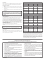
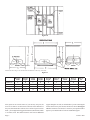
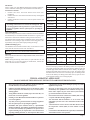
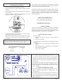
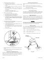
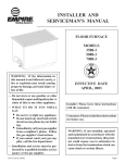
INSTALLER AND
SERVICEMAN'S MANUAL
FLOOR FURNACE
MODELS
3588-3
5088-4
7088-4
Installer: Leave this manual with the appliance.
Consumer: Retain this manual for future reference.
WARNING: If the information in these instructions are not followed exactly, a fire or explosion may result causing property damage,
personal injury or loss of life.
— Do not store or use gasoline or other flammable vapors and liquids in the vicinity of this or
any other appliance.
WARNING: If not installed, operated and
maintained in accordance with the manufacturer's instructions, this product could
expose you to substances in fuel or from
fuel combustion which can cause death or
serious illness.
— WHAT TO DO IF YOU SMELL GAS
• Do not try to light any appliance.
• Do not touch any electrical switch; do not
use any phone in your building.
• Immediately call your gas supplier from a
neighbor’s phone. Follow the gas supplier’s instructions.
• If you cannot reach your gas supplier, call
the fire department.
— Installation and service must be performed
by a qualified installer, service agency or the
gas supplier.
Page 1
Introduction
Always consult your local Building Department regarding regulations,
codes or ordinances which apply to the installation of a floor furnace.
Instructions to Installer
1. Installer must leave instruction manual with owner after installation.
2. Installer must have owner fill out and mail warranty card supplied
with furnace.
3. Installer should show owner how to start and operate furnace and
thermostat.
Specifications
Models
5088
7088
45,000
65,000
Register Length &
Width
33 3/4" x 22 3/4"
36 3/4" x 24 3/4"
36 3/4" x 32 3/4"
Casing Length &
Width
32" x 20"
34" x 22"
34" x 30"
Overall Length
Including Diverter
40"
43 1/2"
45 1/4"
32 5/16" x 20 5/16"
34 5/16" x 22 5/16"
34 5/16" x 30 5/16"
23"
26"
27"
Dimensions
Warning:
Any change to this furnace or its control can be dangerous. This
is a heating appliance and any panel, door or guard removed for
servicing an appliance must be replaced prior to operating the
appliance.
Floor Opening,
Length & Width
Height
Minimum Clearance to Combustibles
Top Must Be Open and Clear of ALL OBJECTS and Covering Each Side to:
General Information
This series is design certified in accordance with American National Standard
Z21.86b-2002 by the Canadian Standards Association as a gravity type
Floor Furnace and must be installed according to these instructions.
Any alteration of the original design, installed other than as shown in
these instructions or use with a type of gas not shown on the rating plate
is the responsibility of the person and company making the change.
Qualified Installing Agency
The installation must conform with local codes, in the absence of local
codes, with the National Fuel Gas Code ANSI Z2231*
Nearest Wall
6"
6"
6"
Bottom of Unit
for Air
6"
6"
6"
Draft Diverter and
Vent Connector
6"
6"
6"
Two Adjoining Sides
to Walls to Provide a
Walkway
18"
18"
18"
Iron pipe Size
(N.P.T.)
1/2"
1/2"
1/2"
Inlet to Floor
18 1/2"
20 1/4"
20 1/4"
Floor to Top of
Diverter Shield
10 1/2"
12 3/4"
12 3/4"
Center of Flue
(Horizontal) to Floor
Covering
17 1/4"
18 3/4"
17 3/4"
Size of Flue Collar
4" Dia.
4" Dia.
5" Dia.
Gas Inlet
*Available from the American National Standards Institute, Inc. 11 West 42nd St., New York,
N.Y. 10018.
State of Massachusetts: The installation must be made by a licensed
plumber or gas fitter in the Commonwealth of Massachusetts.
Important
All correspondence should refer to complete Model Number, Serial Number
and type of gas.
Notice: During initial firing of this furnace, its paint will bake out and
smoke will occur. To prevent triggering of smoke alarms, ventilate the
room in which the furnace is installed.
3588
32,500
Input BTU/HR
Venting
The flue pipe diameter must be as large as the flue collar on the draft diverter
and run as directly as possible to the chimney at least 1/4" rise per foot of
run properly supported by metal straps, and enter the chimney so the end
of the flue pipe is flush with the inner wall of the chimney. Any flue pipe
passing through walls and roof must be "B" type vent. The chimney must
extend at least two feet above the roof and any object or building within
10 feet of the chimney. The flue pipe must NOT have any open tees or be
connected to the chimney of an existing fireplace.
THIS IS A HEATING APPLIANCE
DO NOT OPERATE THIS APPLIANCE WITHOUT FLOOR REGISTER INSTALLED
•
Due to high temperatures the appliance should be located out
of traffic and away from furniture and draperies.
•
Children and adults should be alerted to the hazards of high
surface temperatures and should stay away to avoid burns or
clothing ignition.
•
compartments, burners and circulating air passageways of the
appliance be kept clean.
•
Young children should be carefully supervised when they are
in the same room as the appliance.
DO NOT use this heater if any part has been under water.
Immediately call a qualified service technician to inspect the
heater and to replace any part of the control system and any
gas control which has been under water.
•
•
Clothing or other flammable material should not be placed on
or near the appliance.
Floor furnace must not be connected to a chimney flue serving
a separate solid fuel burning appliance.
•
•
Any safety screen or guard removed for servicing an appliance
must be replaced prior to operating the appliance.
The draft hood shall be installed so as to be in the same
atmospheric pressure zone as the combustion air inlet to the
appliance.
•
Installation and repair should be done by a QUALIFIED
SERVICE PERSON. The appliance should be inspected before
use and at least annually by a qualified service person. More
frequent cleaning may be required due to excessive lint from
carpeting, bedding materials, etc. It is imperative that control
•
A burn hazard can occur in the use of the floor furnace when the
temperature control (limit) is in the manual override position.
•
Contact of bare skin with the hot air register may result in burns
when the floor furnace is in operation.
23228-2-1007
Page 2
SAFETY INFORMATION FOR USERS OF LP-GAS
Propane (LP-Gas) is a flammable gas which can cause fires
and explosions. In its natural state, propane is odorless and
colorless. You may not know all the following safety precautions
which can protect both you and your family from an accident.
Read them carefully now, then review them point by point
with the members of your household. Someday when there
may not be a minute to lose, everyone's safety will depend on
knowing exactly what to do. If, after reading the following
information, you feel you still need more information, please
contact your gas supplier.
LP-GAS WARNING ODOR
If a gas leak happens, you should be able to smell the gas because of the odorant put in the LP-Gas.
That's your signal to go into immediate action!
•
Do not operate electric switches, light matches, use your
phone. Do not do anything that could ignite the gas.
•
Get everyone out of the building, vehicle, trailer, or area. Do
that IMMEDIATELY.
•
Close all gas tank or cylinder supply valves.
•
LP-Gas is heavier than air and may settle in low areas such
as basements. When you have reason to suspect a gas leak,
keep out of basements and other low areas. Stay out until
firefighters declare them to be safe.
•
Use your neighbor's phone and call a trained LP-Gas service
person and the fire department. Even though you may not
continue to smell gas, do not turn on the gas again. Do not
re-enter the building, vehicle, trailer, or area.
•
Finally, let the service man and firefighters check for escaped
gas. Have them air out the area before you return. Properly
trained LP-Gas service people should repair the leak, then
check and relight the gas appliance for you.
NO ODOR DETECTED - ODOR FADE
Some people cannot smell well. Some people cannot smell the
odor of the chemical stench put into the gas. You must find out
if you can smell the odorant in propane. Smoking can decrease
your ability to smell. Being around an odor for a time can affect
your sensitivity or ability to detect that odor. Sometimes other
odors in the area mask the gas odor. People may not smell the
gas odor or their minds are on something else. Thinking about
smelling a gas odor can make it easier to smell.
The odorant in LP-gas is colorless, and it can fade under some
circumstances. For example, if there is an underground leak, the
movement of the gas through soil can filter the odorant. Odorants
in LP-Gas also are subject to oxidation. This fading can occur if
there is rust inside the storage tank or in iron gas pipes.
The odorant in escaped gas can adsorb or absorb onto or into walls,
masonry and other materials and fabrics in a room. That will take
some of the odorant out of the gas, reducing its odor intensity.
LP-Gas may stratify in a closed area, and the odor intensity could
vary at different levels. Since it is heavier than air, there may be
more odor at lower levels. Always be sensitive to the slightest gas
odor. If you detect any odor, treat it as a serious leak. Immediately
go into action as instructed earlier.
SOME POINTS TO REMEMBER
•
Learn to recognize the odor of LP-gas. Your local LP-Gas
Dealer can give you a "Scratch and Sniff" pamphlet. Use it
to find out what the propane odor smells like. If you suspect
that your LP-Gas has a weak or abnormal odor, call your
LP-Gas Dealer.
•
If you are not qualified, do not light pilot lights, perform service,
or make adjustments to appliances on the LP-Gas system. If
you are qualified, consciously think about the odor of LP-Gas
prior to and while lighting pilot lights or performing service
or making adjustments.
•
Sometimes a basement or a closed-up house has a musty
smell that can cover up the LP-Gas odor. Do not try to light
pilot lights, perform service, or make adjustments in an area
where the conditions are such that you may not detect the
odor if there has been a leak of LP-Gas.
•
Odor fade, due to oxidation by rust or adsorption on walls
of new cylinders and tanks, is possible. Therefore, people
should be particularly alert and careful when new tanks or
cylinders are placed in service. Odor fade can occur in new
tanks, or reinstalled old tanks, if they are filled and allowed
Page 3
to set too long before refilling. Cylinders and tanks which
have been out of service for a time may develop internal rust
which will cause odor fade. If such conditions are suspected
to exist, a periodic sniff test of the gas is advisable. If you
have any question about the gas odor, call your LP-gas
dealer. A periodic sniff test of the LP-gas is a good safety
measure under any condition.
•
If, at any time, you do not smell the LP-Gas odorant and you
think you should, assume you have a leak. Then take the same
immediate action recommended above for the occasion when
you do detect the odorized LP-Gas.
•
If you experience a complete "gas out," (the container is under no vapor pressure), turn the tank valve off immediately.
If the container valve is left on, the container may draw in
some air through openings such as pilot light orifices. If this
occurs, some new internal rusting could occur. If the valve is
left open, then treat the container as a new tank. Always be
sure your container is under vapor pressure by turning it off
at the container before it goes completely empty or having it
refilled before it is completely empty.
23228-2-1007
INSTALLATION PLANNING
Plan the furnace installation with three questions in mind:
1.
Where is the heat most needed in the house?
2.
Where should the furnace be so that it will vent properly?
3.
Where should it be placed so that it is not in home traffic areas
or walkways?
Remember! Good Venting is essential to Good Heating.
VENTING
The installer must consider all of the following venting rules. They
will help plan where and how to install the furnace.
1.
Flue pipe MUST always have an upward slope (1/4 inch per
foot minimum). See Figure 1.
Figure 3
NOTE: Do not use Type C single wall flue pipe. Uninsulated
single-wall metal pipe shall not be used outdoors in
cold climates for venting gas utilization equipment.
4.
For flue pipe running through walls, roof and within one (1)
inch of combustible construction, use B-1 (one inch clearance
to combustibles) vent pipe. See Figure 4. Any combustible
material that is within 6 inches of the vent connection or the
draft diverter must be shielded with a non-combustible material.
Figure 1
2.
Flue pipe MUST NOT have any downward sloping sections,
dips or sags. See Figures 2 and 3.
3.
Flue pipe MUST be Type B (double wall insulated).
Figure 4
Figure 2
23228-2-1007
5.
Flue pipe MUST run as directly as possible and have as few
elbows as possible.
6.
Flue pipe MUST be as large as the flue collar on the draft
diverter. See Figure 5.
7.
The flue pipe MUST be on the outside of the draft diverter
collar. See Figure 6.
8.
Each new piece of flue pipe that is connected when getting
farther away from the furnace MUST connect on the outside
of the previous one. See Figure 6. Remember, the exhaust
must flow "into" the next pipe.
9.
The flue pipe MUST NOT be connected to a chimney that has
a fireplace connected to it. See Figure 3.
Page 4
Here are some suggestions.
1. If you have a choice, select a location close to the chimney.
2. If there is no chimney, you will have to run a flue pipe from
the furnace, up to and above the house roof. See Figure 1.
Select a location permitting the most direct run. Try going
up to the roof through a closet. Remember that the flue pipe
must slope upwards at least 1/4 of an inch for each foot and
you may find floor joints in our path, so it is important to plan
the run carefully. See Figure 8.
Figure 5
10. When connecting the flue pipe to the chimney, the pipe MUST
go fully in and be cemented. See Figure 7. The flue pipe
MUST NOT go too far into the chimney. It should be cut off
as it will interfere with normal venting. See Figure 7.
11. The flue pipe MUST be sealed. No open "Tees." See Figure
5.
Figure 8
3.
If you have decided to go up to the roof through a closet, remember that you MUST keep a minimum distance of 1 inch
between Type B vent pipe and any combustible material. See
Figure 9. Run it through a single wall pipe that is 2 inches
larger in diameter than the flue pipe. Use thimbles when going through floor and ceiling and flashing when going through
roof.
Figure 6
12. The flue pipe's vertical rise MUST always be at least twice the
length of the horizontal run.
Figure 7
Figure 9
Page 5
23228-2-1007
4.
Position the furnace so that the long sides are running the same
way as the floor joists (see 10), so that you will only have to
cut one joist. Be sure you install headers or cross supports
between each joist next to the one you cut (see 10). If the furnace is narrow, you will have to also run an additional furnace
support between the two headers or cross supports you add
(see 10). There is a "Cutout Template" in the box the furnace
came in. It is the exact size for the opening needed in the floor
to fit the furnace. Use the cardboard template when preparing
and cutting the floor but always double check the dimensions
(see Table on next page). HINT: When you cut the joist, don't
forget to allow for the thickness of the two headers you will
install. Each one is about 1 1/2 inches thick. Since you will
be using two of them, that is a total of 3 inches.
5. If the house has a sealed or unventilated foundation, an opening will have to be provided to admit air for burning at the
burner. The opening or vent MUST BE at least 1 square inch
per thousand BTUs. (The owner will also have to provide
a gate or door as an entrance to the crawl space so that the
serviceman can get to the bottom of the furnace for making
any necessary adjustments.) The furnace must have at least 6
inches clearance at the bottom.
6. If you have a completely open foundation strong winds will
cause your burner to flutter, make noise and cause the pilot
to go out. The best setting for a furnace is an enclosed but
ventilated foundation with an access door or gate.
CUTTING THE FLOOR
HERE'S HOW TO DO IT
1.
Place the template on the floor where you want the furnace and
draw an outline on the floor around the template. Recheck the
dimensions carefully.
2.
Remove the template and drive a long nail through the floor
within the outline. If you hit a joist instead of going through,
try another spot within the outline.
3.
Go below and find where the nail came through, so you will
know where the furnace will be located downstairs.
4.
If the furnace location does not have to be exact, plan on placing the furnace against one of the joists. See Figure 10.
5.
Cut out some of the floor along the joist so that you can look
through and see where you are. Use that joist and cutout as
a guide by laying the template along it, and draw a new outline.
6.
Cut away the flooring around the outline but do not cut the
joist yet. Remember that the joist has to be cut back farther
than the flooring to make room for the headers. See Figure
10.
7.
Place jacks or supports under the joist that is to be cut. This
will prevent the joist sagging and pinching the saw when you
are cutting.
8.
Move any heavy furniture, or appliance (refrigerator) away
from the area where the joist is being cut. If not properly supported, the floor could sag and furniture could fall on you.
9.
Cut through the joist at each end and remove. Put the header
in place and jack it up against the floor. See Figure 10. Make
sure it is butted up against the end of the joist you have just
cut. Use the template to make sure the header is square to the
two joists on each side of it.
10. Drive three large nails through each of the joists and into each
end of the header. Now drive three large nails through the
header and into the end of the joist just cut. Install the other
header in the same way. See Figure 10.
11. Use the template to position the additional furnace support and
then nail the support in place by driving three nails into each
end of it, through the headers. See Figure 10.
12. Remove the jacks and supports.
13. Make sure the furnace is facing the way you want it with draft
diverter closet to the vent pipe chimney. Then, with someone
helping you, slowly lower it into the opening.
14. Drive two nails through each side and at least one nail through
each end of the furnace from the inside into each joist and
header that surrounds it.
23228-2-1007
Page 6
Figure 10
*Dotted lines show the gas valve and flue collar for Model No. 3588 only. (Same side)
Figure 11
Model No.
3588
5088
7088
Register
width
A
22 3/4
24 3/4
32 3/4
Register
length
B
34 3/4
36 3/4
36 3/4
Casing
width
C
20
22
30
Casing
length
D
32
34
34
Floor joists are on 16-inch centers. If you cut away one joist, the
next two are then on 32-inch centers. Because of the thickness of
the joists, that means there is about 30 1/2 inches of space between
them—just enough for the biggest floor furnace, Model 7088, which
is 30 inches wide. The smaller furnaces will need an additional
Page 7
Overall
height
E
24
26
27
Floor to
Flue C.
F
15 1/4
16 3/4
15 1/4
Floor to
shield
G
10 1/2
12 3/4
12 3/4
Floor to
gas inlet
H
18 1/2
20 1/4
20 1/4
Flue C.
size
I
4 D.
4 D.
5 D.
support along the one side, or on both sides if you are centering the
furnace between two joists because location is critical. See Figure
10. If the location is not critical, it is easier for you to put the furnace
against a joist and then fill in with one additional support.
23228-2-1007
INSTALLING DRAFT DIVERTER
The draft diverter mounts on the exhaust end of the furnace with
four #10 x 1/2" sheet metal screws. The holes are already drilled
in the furnace and the screws are supplied with the furnace. Make
sure collars of the diverter go outside the collars on the furnace.
When the diverter is tightened against the furnace, its collars should
be embedded into the gasket in the recesses.
Figure 12
After the installation of the diverter as shown, do not install walls
or partitions that would place the diverter in a different pressure
zone than the combustion air for the main burner.
DEBRIS PAN
A flat rectangular burner pan (debris pan) is attached to the burner.
This pan is designed to catch hot particles that might drop from the
combustion chamber. SEE LABEL ON SIDE OF FURNACE.
The state of Massachusetts requires that a flexible appliance connector cannot exceed three feet in length.
The gas inlet to the furnace is 1/2 inch nominal pipe thread. Use
at least 1/2 inch pipe to avoid excessive pressure drop; check local codes. Install the piping in accordance with the requirements
described in Installation Planning.
Compounds used on threaded joints of gas piping shall be resistant
to the action of liquefied petroleum gases. The gas lines must be
checked for leaks by the installer. This should be done with a soap
solution watching for bubbles on all exposed connections and,
if unexposed, a pressure test should be made. NEVER USE AN
EXPOSED FLAME TO CHECK FOR LEAKS. Appliance must
be disconnected from piping at inlet of control valve, and pipe
capped or plugged for pressure test. NEVER PRESSURE TEST
WITH APPLIANCE CONNECTED; CONTROL VALVE WILL
SUSTAIN DAMAGE.
TESTING THE SUPPLY PIPING
The appliance and its individual shutoff valve must be disconnected
from the gas supply piping system during any pressure testing of
that system at test pressures in excess of 1/2 psig (3.5kPa).
The appliance must isolated from the gas supply piping system by
closing its individual manual shut off valve during any pressure
testing of the gas supply piping system at test pressures equal to
or less than 1/2 psig (3.5 kPa).
ATTENTION! If one of the above procedures results in pressures
in excess of 1/2 psig (14 in. w.c.) (3.5 kPa) on the appliance gas
valve, it will result in a hazardous condition.
WALL THERMOSTAT
No wire is supplied with the thermostat because the wire size
depends on low long the wire has to be.
It is important to use wire of a gauge proper for the length of the
wire:
RECOMMENDED WIRE GAUGES
Maximum Length
Wire Gauge
1' to 10'
18
10' to 25'
16
25' to 35'
14
Thermostat is mounted to the wall with two screws that are supplied. Mount the thermostat about 4 to 5 feet up from the floor,
in the room heated by the furnace, and exposed to normal free air
circulation.
Connect thermostat to gas valve terminals as shown in 14.
Figure 13
Method of Installing a Tee Fitting Sediment Trap
In the state of Massachusetts the gas cock must be a T handle
type.
To check the inlet pressure to the gas valve, a 1/8" N.P.T. plugged
tapping, accessible for test gauge connection must be placed immediately upstream of the gas supply connection to the appliance.
GAS CONNECTIONS
1. A manual valve and ground-joint type union should be installed
close to the furnace for servicing.
2. A "drip" shall be put in the gas line to collect condensate or
dirt. This can be a "tee" fitting near the furnace inlet with an
extension downward that is capped.
3. Use a large enough pipe to prevent excessive pressure drop. The
pipe should be at least the size of the opening on the furnace
inlet.
23228-2-1007
Figure 14
Page 8
OPERATING INFORMATION
PIEZO LIGHTING INSTRUCTIONS
This unit is equipped with a Piezo (spark) for lighting the pilot
without removing the lighter hole cover. A lighter rod is supplied
and can be used to see if the pilot is getting gas and also for faster
lighting when there is excessive air in the lines.
REGISTER TEMPERATURE CONTROLS
The register temperature control has two positions. LOW HEAT
(Black) output and FULL HEAT (Red) output. Use the low position when children are present. This will cause your furnace to
turn off and on several times before the living area is completely
comfortable. This is normal and limits the register temperature to
a maximum of 235°F.
SOME HELPFUL WARNINGS
• Use low heat output when children are nearby.
• Do not cover the floor register when the furnace or pilot is
turned on.
• Do not restrict the flow of air around the register by placing a
screen under it.
• Do not dry clothes or any objects by putting them on floor
register because this creates a fire hazard.
CAUTION
Contact of bare skin on the hot air register may result in burns when
the appliance is in operation. KEEP CHILDREN OFF!
You can reduce the heat of the register by moving the register
temperature control.
MILLIVOLT INFORMATION
500 average with the thermostat OFF.
225 average with the thermostat ON.
140 minimum for valve to open.
65 minimum for pilot to stay on.
CAUTION: Label all wires prior to disconnection when servicing controls. Wiring errors can cause improper and dangerous
operation. Verify operation after servicing.
Figure 15
• Do not hang clothes or any object above or over floor register
because this too creates a fire hazard.
• During warm weather months, turn to full OFF position before
you cover the register with a rug, because this too creates a
fire hazard.
CAUTION
NEVER run your furnace with the lighter hole open or with a
broken lighter hole window. Exhaust gases can get into the living
area through an open lighter hole and be fatal.
TROUBLESHOOTING INFORMATION
A. All units have been fire-tested to check the operation of the
furnace. This includes the BTU input, main burner flame, pilot
flame, limit controls and automatic operation. If problems are
encountered on initial installation the following should be
checked
1. Is the unit equipped for the gas being used?
2. Are all of the wires connected to the gas valve properly?
3. Is the venting system functioning? Check for spillage at
the diverter.
4. Is the gas inlet pressure proper? Read instructions for
minimum pressure.
B. It is necessary to use a millivolt meter to determine if the power
from the generator is adequate. 500 millivolts is normal with
the thermostat off and 140 millivolts minimum with thermostat
on.
Page 9
C. This floor furnace cannot be expected to function properly if
exposed to wind as found when installed in a house supported
by pillars (open foundation). The wind is most harmful if it
can go beneath the front of the draft diverter and produce a
pressure directly on the outlet of the chamber. This wind can
result in pilot outage and a reduction in millivolts, causing the
valve not to open.
D. Good operation of the system is dependent on the pilot and
generator working properly. It is possible for the pilot to require
cleaning yearly. Replace pilot assembly if cleaning does not
produce proper flame. Replacement on generator alone is not
recommended.
E. Gas Valve will not open. To determine problem area:
1. By-pass thermostat on the wall.
2. By-pass thermostat at the valve.
3. By-pass limit and thermostat at the valve.
4. Check millivolts.
23228-2-1007
FOR YOUR SAFETY READ BEFORE LIGHTING
WARNING: If you do not follow these instructions exactly, a fire or explosion may result causing property damage, personal injury or loss of life.
A. This appliance has a pilot which must be lighted by
hand. When lighting the pilot, follow these instructions
exactly.
B. BEFORE LIGHTING smell all around the appliance area
for gas. Be sure to smell next to the floor because some
gas is heavier than air and will settle on the floor.
WHAT TO DO IF YOU SMELL GAS
• Do not try to light any appliance.
• Do not touch any electrical switch; do not use any
phone in your building.
• Immediately call your gas supplier from a neighbor's
phone. Follow the gas supplier's instructions.
•
If you cannot reach your gas supplier, call the fire
department.
C. Use only your hand to push in or turn the gas control knob.
Never use tools. If the knob will not push in or turn by
hand, don't try to repair it, call a qualified service technician. Force or attempted repair may result in a fire or
explosion.
D. Do not use this appliance if any part has been under water.
Immediately call a qualified service technician to inspect
the appliance and to replace any part of the control system
and any gas control which has been under water.
LIGHTING INSTRUCTIONS
1.
STOP! Read the safety information above.
2.
Set the thermostat to lowest setting.
3.
Remove floor register.
NOTE: The gas control rod is attached to the gas control
knob.
4.
Push in gas control rod slightly and turn clockwise
to "OFF."
7.
8.
9.
NOTE: Rod cannot be turned from "PILOT" to "OFF"
unless rod is pushed in slightly. Do not force.
Find pilot - the pilot is
adjacent to the center
portion of the main
burner in the area directly below the pilot
access opening.
3588
5088
7088
Turn gas control rod counterclockwise
to "PILOT."
Push and hold control rod in and repeatedly push the
ignitor button until pilot is lit (or use match and lighter
rod to light.) Continue to hold the control rod in for about
one (1) minute after the pilot is lit. Release rod and it will
pop back up. Pilot should remain lit. If it goes out, repeat
steps 4 through 9.
• If rod does not pop up when released, stop and immediately call a qualified service technician or gas
supplier.
• If the pilot will not stay lit after several tries, turn
the gas control rod to "OFF" and call your service
technician or gas supplier.
5.
Remove the pilot access cover located on the combustion
chamber.
10. Replace pilot access cover.
6.
Wait ten (10) minutes to clear out any gas. Then smell
for gas, including near the floor. If you smell gas, STOP!
Follow "B" in the safety information above. If you don't
smell gas, go to the next step.
12. Replace floor register.
to
11. Turn gas control knob counterclockwise
"ON."
13. Set thermostat to desired setting.
TO TURN OFF GAS TO APPLIANCE
1.
Set the thermostat to lowest setting.
2.
Remove floor register.
23228-2-1007
3.
Push in gas control rod slightly and turn clockwise
to "OFF." Do not force.
4.
Replace floor register.
Page 10
PROPER MAIN BURNER FLAME
AND PILOT FLAME 3588
PROPER PILOT BURNER FLAME 5088, 7088
A blue flame shooting toward the main burner with an inner blue cone
and a larger light blue outer flame. The generator will be surrounded
by a blue flame that terminates near the top of the generator.
HIGH ALTITUDES
Orifice size must be reduced for high altitude use, or carbon monoxide
may be generated and excessive heat will seriously damage the unit.
When altitudes over 2,000 feet are specified, in the United States,
main burner spuds will be furnished to reduce input 4% for each
1,000 feet of altitude above sea level. Contact the manufacturer
or your gas company before changing spud sizes.
Figure 16
The correct pilot flame will be blue and extend past the thermopile
as shown in the drawing. LP gas models do not require adjusting.
The input of Natural gas models will require adjusting if the inlet
pressure to the valve is above 5" w.c.
PROPER MAIN BURNER FLAME
5088, 7088
C
CHECKING MANIFOLD PRESSURE
Both Propane and Natural gas valves have a built-in pressure
regulator in the gas valve with factory-set adjustment. Natural gas
models should have a manifold pressure of approximately 3.5"
w.c. at the valve outlet with the inlet pressure to the valve from a
minimum of 5.0" w.c. for the purpose of input of input adjustment
to a maximum of 7.0" w.c. Propane gas models will have a manifold
pressure approximately 10.0" w.c. at the valve outlet with the inlet
pressure to the valve from a minimum of 11.0" w.c. for the purpose
of input adjustment to a maximum of 13.0" w.c.
An 1/8" N.P.T. plugged tapping, accessible for test gage connection,
is located on the outlet side of the gas control.
B
CLEANING THE MAIN BURNER
A
Remove the burner and apply air pressure inside the throat of the
burner and down into the ports.
Check for proper burner and pilot flame before and during each
heating season.
SERVICING
Figure 17
Model
7088
5088
Gas
Nat
LP
Nat.
LP
Inner Cone
(A) Dark blue
1 inch
3/4 inch
3/4 inch
1/2 inch
Outer Cone
(B) Light blue
2 1/2 inches
2 inches
2 inches
1 1/2 inch
Carry down flame
(C) Blue
1/4 inch
small cone
3/16 inch
small cone
DO NOT MISTAKE AN ORANGE FLAME CAUSED BY PARTICLES IN THE AIR FOR THE UNDESIRABLE YELLOW
FLAME.
INSTALLATION AND REPAIR SHOULD BE DONE BY A
QUALIFIED SERVICE PERSON. The appliance should be
inspected before use and at least annually by a professional service
person. More frequent cleaning may be required due to excessive
lint from carpeting, bedding material, etc. It is imperative that
control compartments, burners and circulating air passageways of
the appliance be kept clean.
Floor furnace must not be connected to a chimney flue servicing
a separate solid-fuel burning appliance.
DON'T put anything around the furnace that will obstruct the
flow of combustion and ventilation air.
DO keep the appliance area clear and free from combustible
material, gasoline and other flammable vapors and liquids.
DO examine venting system periodically and replace damaged
parts.
DO examine burners periodically. Clean and replace damaged
parts.
FLAME 360° AROUND
GENERATOR - COMING
TO TOP OF GENERATOR
MAKE periodic visual check of pilot and burner flame.
Figure 17
Page 11
23228-2-1007
EXPLODED VIEW
20
21
22A
23
22B
24
25
23228-2-1007
Page 12
PARTS LIST
PLEASE NOTE: When ordering parts, it is very important that part number and description of part coincide.
INDEX
NO.
DESCRIPTION
3588
5088
7088
1
FF-139
23226
23225
OUTER CASING
2
FF-294
23216
23216
CONTROL ROD
3
FF-038
FF-016
FF-038
FLANGE TUBE OUTLET
4
FF-189
FF-190
FF-189
GASKET FLANGE TUBE OUTLET
5
FF-066
FF-032
FF-027
DRAFT DIVERTER
6
FF-169
FF-169
FF-169
LIGHTER ROD
7
FF-078
FF-077
FF-077
DEBRIS PAN
8
FF-293
FF-293
FF-293
VALVE BRACKET
9
FF-261
P-262
P-262
MANIFOLD ASSEMBLY
PART NO.
10
FF-296
FF-297
FF-297
PILOT TUBING WITH FERRELLS
11
762141
R-715N
R-715N
PILOT BURNER WITH THERMOPILE - NATURAL GAS
11
762247
R-715L
R-715L
PILOT BURNER WITH THERMOPILE - LP GAS
12
602032
23218
23217
BURNER
13
732010
FF-250
FF-250
ELECTRODE AND WIRE
14
R-2313
R-2313
R-2313
PIEZO IGNITOR
15
742169
P-8631
P-8625
BURNER ORIFICE - NATURAL GAS
15
742296
P-8648
P-8643
BURNER ORIFICE - LP GAS
16
R-5788
R-5788
R-5788
WALL THERMOSTAT 750 MILLIVOLT
17
R-5624
R-5625
R-5626
REGISTER
18
FF-291
FF-268
FF-270
INNER CASING
19
FF-003
FF-272
FF-273
COMBUSTION CHAMBER
20
DV-064
DV-064
DV-064
PLATE FOR OBSERVATION HOLE COVER
21
DV-781
DV-781
DV-781
OBSERVATION HOLE COVER WITH MICA
22A
R-1820
R-1822
R-1822
REGISTER LIMIT SWITCH
22B
R-1821
R-1821
R-1821
PRIMARY LIMIT SWITCH
23
FF-298
FF-299
FF-300
CAUTION PLATE ASSEMBLY
24
R-5605
R-5605
R-5605
VALVE - LP GAS
24
R-5606
R-5606
R-5606
VALVE - NATURAL GAS
25
-
FF-292
-
AIR SHUTTER (LP ONLY)
Not Shown
R-1081
R-921N
R-921N
PILOT ORIFICE - NATURAL GAS
Not Shown
R-1089
R-921L
R-921L
PILOT ORIFICE - LP GAS
Not Shown
R-942
672010
672010
THERMOPILE
Page 13
23228-2-1007
HOW TO ORDER REPAIR PARTS
Parts can be ordered only through your service person or dealer. For best results, the service person or dealer should order parts
through the distributor. Parts can be shipped directly to the service person/dealer.
All parts listed in the Parts List have a Part Number. When ordering parts, first obtain the Model Number from the name plate on your
equipment. Then determine the Part Number (not the Index Number) and the Description of each part from the following appropriate
illustration and list. Be sure to give all this information . . .
Heater Number
Part Description
Heater Serial Number
Part Number
Type of Gas (Propane or Natural)
Do not order bolts, screws, washers or nuts. They are standard hardware items and can be purchased at any local hardware store.
Shipments contingent upon strikes, fires and all causes beyond our control.
SERVICE NOTES
23228-2-1007
Page 14
SERVICE NOTES
Page 15
23228-2-1007
Empire Comfort Systems, Inc.
918 Freeburg Ave. Belleville, IL 62220
PH: 618-233-7420 or 800-851-3153
FAX: 618-233-7097 or 800-443-8648
[email protected]
www.empirecomfort.com
23228-2-1007
Page 16
OWNER'S MANUAL
FLOOR FURNACE
MODELS
3588-3
5088-4
7088-4
WARNING: If the information in these instructions are not followed exactly, a fire or explosion may result causing property damage,
personal injury or loss of life.
— Do not store or use gasoline or other flammable vapors and liquids in the vicinity of this or
any other appliance.
— WHAT TO DO IF YOU SMELL GAS
• Do not try to light any appliance.
• Do not touch any electrical switch; do not
use any phone in your building.
• Immediately call your gas supplier from a
neighbor’s phone. Follow the gas supplier’s instructions.
• If you cannot reach your gas supplier, call
the fire department.
— Installation and service must be performed
by a qualified installer, service agency or the
gas supplier.
Installer: Leave this manual with the appliance.
Consumer: Retain this manual for future reference.
WARNING: If not installed, operated and
maintained in accordance with the manufacturer's instructions, this product could
expose you to substances in fuel or from
fuel combustion which can cause death or
serious illness.
Page 1
Introduction
Always consult your local Building Department regarding regulations,
codes or ordinances which apply to the installation of a floor furnace.
Specifications
Models
3588
5088
7088
32,500
45,000
65,000
Register Length &
Width
33 3/4" x 22 3/4"
36 3/4" x 24 3/4"
36 3/4" x 32 3/4"
Casing Length &
Width
32" x 20"
34" x 22"
34" x 30"
Overall Length
Including Diverter
40"
43 1/2"
45 1/4"
32 5/16" x 20 5/16"
34 5/16" x 22 5/16"
34 5/16" x 30 5/16"
23"
26"
27"
Input BTU/HR
Instructions to Installer
1. Installer must leave instruction manual with owner after
installation.
2. Installer must have owner fill out and mail warranty card supplied
with furnace.
3. Installer should show owner how to start and operate furnace and
thermostat.
Dimensions
Warning:
Any change to this furnace or its control can be dangerous. This
is a heating appliance and any panel, door or guard removed for
servicing an appliance must be replaced prior to operating the
appliance.
Floor Opening,
Length & Width
Height
Minimum Clearance to Combustibles
Top Must Be Open and Clear of ALL OBJECTS and Covering Each Side to:
General Information
This series is design certified in accordance with American National Standard
Z21.86b-2002 by the Canadian Standards Association as a gravity type
Floor Furnace and must be installed according to these instructions.
Any alteration of the original design, installed other than as shown in these
instructions or use with a type of gas not shown on the rating plate is the
responsibility of the person and company making the change.
Qualified Installing Agency
The installation must conform with local codes, or in the absence of local
codes, with the National Fuel Gas Code ANSI Z223.1.
Nearest Wall
6"
6"
6"
Bottom of Unit
for Air
6"
6"
6"
Draft Diverter and
Vent Connector
6"
6"
6"
Two Adjoining Sides
to Walls to Provide a
Walkway
18"
18"
18"
Iron pipe Size
(N.P.T.)
1/2"
1/2"
1/2"
Inlet to Floor
18 1/2"
20 1/4"
20 1/4"
Floor to Top of
Diverter Shield
10 1/2"
12 3/4"
12 3/4"
Center of Flue
(Horizontal) to Floor
Covering
17 1/4"
18 3/4"
17 3/4"
Size of Flue Collar
4" Dia.
4" Dia.
5" Dia.
Gas Inlet
State of Massachusetts: The installation must be made by a licensed
plumber or gas fitter in the Commonwealth of Massachusetts.
Venting
Important
All correspondence should refer to complete Model Number, Serial Number
and type of gas.
Notice: During initial firing of this furnace, its paint will bake out and
smoke will occur. To prevent triggering of smoke alarms, ventilate the
room in which the furnace is installed.
The flue pipe diameter must be as large as the flue collar on the draft diverter
and run as directly as possible to the chimney at least 1/4" rise per foot of
run properly supported by metal straps, and enter the chimney so the end
of the flue pipe is flush with the inner wall of the chimney. Any flue pipe
passing through walls and roof must be "B" type vent. The chimney must
extend at least two feet above the roof and any object or building within
10 feet of the chimney. The flue pipe must NOT have any open tees or be
connected to the chimney of an existing fireplace.
THIS IS A HEATING APPLIANCE
DO NOT OPERATE THIS APPLIANCE WITHOUT FLOOR REGISTER INSTALLED
•
Due to high temperatures the appliance should be located out
of traffic and away from furniture and draperies.
•
Children and adults should be alerted to the hazards of high
surface temperatures and should stay away to avoid burns or
clothing ignition.
•
compartments, burners and circulating air passageways of the
appliance be kept clean.
•
Young children should be carefully supervised when they are
in the same room as the appliance.
DO NOT use this heater if any part has been under water.
Immediately call a qualified service technician to inspect the
heater and to replace any part of the control system and any
gas control which has been under water.
•
•
Clothing or other flammable material should not be placed on
or near the appliance.
Floor furnace must not be connected to a chimney flue serving
a separate solid fuel burning appliance.
•
•
Any safety screen or guard removed for servicing an appliance
must be replaced prior to operating the appliance.
The draft hood shall be installed so as to be in the same
atmospheric pressure zone as the combustion air inlet to the
appliance.
•
Installation and repair should be done by a QUALIFIED
SERVICE PERSON. The appliance should be inspected before
use and at least annually by a qualified service person. More
frequent cleaning may be required due to excessive lint from
carpeting, bedding materials, etc. It is imperative that control
•
A burn hazard can occur in the use of the floor furnace when
the temperature control (limit) is in the manual override
position.
•
Contact of bare skin with the hot air register may result in burns
when the floor furnace is in operation.
23228-2-1007
Page 2
SAFETY INFORMATION FOR USERS OF LP-GAS
Propane (LP-Gas) is a flammable gas which can cause fires
and explosions. In its natural state, propane is odorless and
colorless. You may not know all the following safety precautions which can protect both you and your family from an
accident. Read them carefully now, then review them point
by point with the members of your household. Someday when
there may not be a minute to lose, everyone's safety will depend
on knowing exactly what to do. If, after reading the following
information, you feel you still need more information, please
contact your gas supplier.
LP-GAS WARNING ODOR
If a gas leak happens, you should be able to smell the gas because of the odorant put in the LP-Gas.
That's your signal to go into immediate action!
•
Do not operate electric switches, light matches, use your
phone. Do not do anything that could ignite the gas.
•
Get everyone out of the building, vehicle, trailer, or area. Do
that IMMEDIATELY.
•
Close all gas tank or cylinder supply valves.
•
LP-Gas is heavier than air and may settle in low areas such
as basements. When you have reason to suspect a gas leak,
keep out of basements and other low areas. Stay out until
firefighters declare them to be safe.
•
Use your neighbor's phone and call a trained LP-Gas service
person and the fire department. Even though you may not
continue to smell gas, do not turn on the gas again. Do not
re-enter the building, vehicle, trailer, or area.
•
Finally, let the service man and firefighters check for escaped
gas. Have them air out the area before you return. Properly
trained LP-Gas service people should repair the leak, then
check and relight the gas appliance for you.
NO ODOR DETECTED - ODOR FADE
Some people cannot smell well. Some people cannot smell the
odor of the chemical stench put into the gas. You must find out
if you can smell the odorant in propane. Smoking can decrease
your ability to smell. Being around an odor for a time can affect
your sensitivity or ability to detect that odor. Sometimes other
odors in the area mask the gas odor. People may not smell the
gas odor or their minds are on something else. Thinking about
smelling a gas odor can make it easier to smell.
The odorant in LP-gas is colorless, and it can fade under some
circumstances. For example, if there is an underground leak, the
movement of the gas through soil can filter the odorant. Odorants
in LP-Gas also are subject to oxidation. This fading can occur if
there is rust inside the storage tank or in iron gas pipes.
The odorant in escaped gas can adsorb or absorb onto or into walls,
masonry and other materials and fabrics in a room. That will take
some of the odorant out of the gas, reducing its odor intensity.
LP-Gas may stratify in a closed area, and the odor intensity could
vary at different levels. Since it is heavier than air, there may be
more odor at lower levels. Always be sensitive to the slightest gas
odor. If you detect any odor, treat it as a serious leak. Immediately
go into action as instructed earlier.
SOME POINTS TO REMEMBER
•
Learn to recognize the odor of LP-gas. Your local LP-Gas
Dealer can give you a "Scratch and Sniff" pamphlet. Use it
to find out what the propane odor smells like. If you suspect
that your LP-Gas has a weak or abnormal odor, call your
LP-Gas Dealer.
•
If you are not qualified, do not light pilot lights, perform
service, or make adjustments to appliances on the LP-Gas
system. If you are qualified, consciously think about the odor
of LP-Gas prior to and while lighting pilot lights or performing service or making adjustments.
•
Sometimes a basement or a closed-up house has a musty
smell that can cover up the LP-Gas odor. Do not try to light
pilot lights, perform service, or make adjustments in an area
where the conditions are such that you may not detect the
odor if there has been a leak of LP-Gas.
•
Odor fade, due to oxidation by rust or adsorption on walls of
new cylinders and tanks, is possible. Therefore, people should
be particularly alert and careful when new tanks or cylinders
are placed in service. Odor fade can occur in new tanks, or
reinstalled old tanks, if they are filled and allowed to set too
Page 3
long before refilling. Cylinders and tanks which have been
out of service for a time may develop internal rust which will
cause odor fade. If such conditions are suspected to exist, a
periodic sniff test of the gas is advisable. If you have any
question about the gas odor, call your LP-gas dealer. A
periodic sniff test of the LP-gas is a good safety measure
under any condition.
•
If, at any time, you do not smell the LP-Gas odorant and you
think you should, assume you have a leak. Then take the same
immediate action recommended above for the occasion when
you do detect the odorized LP-Gas.
•
If you experience a complete "gas out," (the container is under no vapor pressure), turn the tank valve off immediately.
If the container valve is left on, the container may draw in
some air through openings such as pilot light orifices. If this
occurs, some new internal rusting could occur. If the valve is
left open, then treat the container as a new tank. Always be
sure your container is under vapor pressure by turning it off
at the container before it goes completely empty or having it
refilled before it is completely empty.
23228-2-1007
GENERAL INSTRUCTIONS
Follow a few simple rules and your Empire furnace will give you years
of trouble-free heating. When your furnace is ready for installation,
operation or repair here are a few DO's and DON'T's.
if you have received everything on the list. If anything is missing
or broken, or if the model or serial numbers are not right, or if
the furnace is for natural and you have propane (or the other way
around), contact your dealer or Empire Comfort Systems, Inc.
DON'T install the furnace yourself if you are not qualified in
working with gas piping, chimneys, flue pipes, and venting. Gas
appliances and gas piping should be installed or repaired only by
a qualified serviceman.
DO get a qualified installing agency to install your furnace. By
the term "qualified installing agency" is meant any individual,
firm, corporation or company which either in person or through a
representative is engaged in and is responsible for the installation or
replacement of gas piping on the outlet side of the meter, or of the
service regulator when a meter is not provided; or the connection,
installation or repair of gas appliances, who is experienced in such
work, familiar with all precautions required; and has complied with
all the requirements of the authority having jurisdiction.
WALL
THERMOSTAT
MANUALS (2)
REGISTER
FLOOR CUTOUT
TEMPLATE
PILOT
LIGHTING
HOLD COVER
INNER
CASING
WARRANTY
CARD
The installation must conform with local codes, or in the absence
of local codes, with the National Fuel Gas Code ANSI Z223.1.
PACKED IN SEPARATE
CARTON
*Available from the American National Standards Institute, Inc., 11 West 42nd St.,
New York, N.Y. 10036.
IDENTIFICATION
PLATE (INSIDE)
DO consult your dealer and local gas supplier about qualified
installers and servicemen.
DO refer to your Empire Installer and Serviceman's Manual so
that you can make sure that all installation and service work was
done properly. You bought the best furnace, now make sure you
get the best service.
DO make sure your venting system and flue pipe were installed as
outlined in your Empire Installer and Serviceman's Manual.
DO see "Using Your Furnace" before you try to light the pilot or
turn your furnace on.
DO see "Using Your Furnace" for instructions on how to set the
register temperature control when children are present.
CAUTION
Floor register becomes hot when operating and can cause burns.
Keep children off!
DON'T adjust or repair the combination valve, and don't take it
apart.
DON'T try to make any repairs except the ones listed for you to
do in Service Checks.
DID YOU GET EVERYTHING?
After you have unpacked your Empire furnace, you should make
certain everything is in order. For example, did you receive the
model furnace you ordered? Is it the model for the type of gas
(Natural or Propane) you want? Did you get all of the parts you
are supposed to have? Look at picture A. It will tell you where
your furnace identification plate is. The plate has stamped on it
the model and serial number of the furnace you received. It also
tells if your furnace is supposed to use natural (NAT) or propane
(LP) gas. See if the serial number on your furnace is the same as
the number on the WARRANTY CARD. Be sure your dealer fills
out the WARRANTY CARD, then MAIL the purchaser's report
(bottom part) to us. Look at Picture A and also the list below to see
23228-2-1007
DRAFT
DIVERTER
LIGHTING ROD
(MATCH HOLDER)
DEBRIS PAN
Figure A
1.
2.
3.
4.
5.
6.
7.
8.
9.
10.
Owner's manual (you are reading it now)
Installer and Serviceman's Manual
Wall thermostat (packed in draft diverter carton)
Draft diverter (packed in separate carton)
Cardboard cutout template (inside top of furnace box)
Register (top of furnace)
Warranty card
Debris pan
Lighting rod (inside furnace lying on bottom)
Inner casing (inside furnace)
HOW YOUR FURNACE WORKS
HEATING
Your Empire furnace uses air from two places; air from outside the
living area, and air from inside the living area. The air from outside
the living area is mixed with gas and burned inside a chamber in
your furnace. The burned gas and air is exhausted through a flue
pipe to the outside air again. This exhaust should not be permitted
to enter the living area.
Burning gas inside the furnace chamber makes the chamber hot.
Cool air from inside the living area is drawn into the furnace and
flows past the outside of the hot chamber. The chamber makes this
air hot and this hot air flows out of the furnace and back into the
living area. When enough air in the living area has been heated,
the thermostat turns the furnace off automatically.
Picture B shows the flow of air inside and air outside the living
area. You can see that the air inside is not mixed with air outside the
living area. The furnace does not burn air that is within your living
area, and burned air or exhaust should not enter the living area.
Page 4
INSULATED VENT ENCLOSURE
Vented floor furnace installed with the vent going directly to the
outside and above the eaves can cause poor venting. The cold
vent pipe will have a delay in proper venting and cause spillage
of flue products at the draft diverter. The spillage of flue products
can result in pilot outage due to recirculation of flue products into
the main burner, also, condensation can occur in the vent pipe
which can cause an ice build-up or rusting of the draft diverter. To
prevent delayed venting as well as condensation of flue products
an insulated vent enclosure is recommended.
Use Type B vent pipe and maintain at least a one inch clearance
to combustibles.
Use metal thimble to protect vent pipe as it passes through
combustibles.
VENTING
Good venting is essential to good dependable heat. Venting removes
the exhaust that results when gas is burned inside your furnace. If
the exhaust is not vented away, the exhaust may gather under your
house and could seep into the house and be fatal. Venting is done
through a vent pipe (chimney) which, when correctly installed,
causes a draft (suction) at the end of the pipe that is connected to
the draft diverter. This suction carries away the exhaust from your
furnace. The vent pipe is connected to the draft diverter which is
mounted onto the furnace during installation. See Figure B. Refer
to the Installer and Serviceman's Manual for instructions on how
to properly vent your furnace. Remember, exhaust fumes, whether
they come from your furnace or your car, can be fatal.
needed, and turn it off when it is comfortable.
WALL THERMOSTAT
The wall thermostat is simply a switch that turns on when it is
cold and off when it is comfortable. When the thermostat turns on
it connects the small amount of electricity to the main gas valve
(part of combination valve in furnace), which then opens. Now
the pilot lights the gas and your furnace is on. When the living
area is warm enough, the wall thermostat switches off, the main
gas valve closes and your furnace turns off. The pilot remains lit
waiting to light the gas the next time the thermostat calls for heat
and turns the furnace on.
TEMPERATURE CONTROLS
Your Empire furnace has two safety switches (limits). When either
switch turns off, it turns your furnace off, even if the wall thermostat
is calling for heat. One of these switches can be moved to a LOW
HEAT or a FULL HEAT position. In FULL HEAT position the
register becomes very hot when the furnace heats the living area.
In LOW HEAT position the switch will turn the furnace off and on
again a few times before the living area is comfortable but it stops
the register from getting as hot as the FULL HEAT position.
DRAFT DIVERTER
The draft diverter is a collection box that is attached to the exhaust
end of your furnace. The draft diverter is a very important unit and
has two major functions:
1.
2.
It dilutes the flue products with cooler air.
It allows the furnace to burn properly during temporary
downdrafts.
Check the draft diverter and entire vent system each year for rust
damage and proper assembly.
COMBINATION VALVE
The combination valve in the furnace controls the gas. This valve
has a control handle with three positions marked: OFF, PILOT
and ON. When the handle is at OFF, all gas is cut off. When the
handle is at PILOT, the pilot can be lit. When the handle is at ON,
the gas will flow to the burner providing the pilot is lit and the wall
thermostat calls for heat.
HOT AIR
HOT AIR
VENT PIPE
(CHIMNEY
TYPE B)
HOT AIR
USING YOUR FURNACE
COOL AIR
COOL AIR
VENT PIPE
OUTSIDE
AIR
GAS
SUPPLY
EXHAUST
OUTSIDE DRAFT
AIR
DIVERTER
BURNER
CHAMBER
OUTSIDE
AIR SUPPLY
Figure B
FURNACE FEATURES
NO ELECTRICITY NEEDED
(Self Generating Pilot Control)
Your Empire furnace does not need electricity from your house;
it makes its own. When the pilot is lit, its heat is used to generate
a tiny amount of electricity (about 1/2 volt) which is all that is
needed by your furnace. This small amount of electricity keeps
the pilot valve (part of combination valve in furnace) open so the
pilot stays on. The small amount of electricity is also used with the
wall thermostat to turn on the furnace automatically when heat is
Page 5
BEFORE YOU TURN IT ON
Look down inside your furnace and make sure there isn't any paper,
packing material, or trash that could catch fire. Turn your thermostat
off or to its lowest temperature setting. See if the furnace control
handle is turned to OFF. See Figure C.
CAUTION
If the furnace control handle was not at OFF, turn it to OFF and
wait ten minutes before lighting a match or the pilot.
NOTE
You must press down on the furnace control handle to make it
turn to OFF.
You are now ready to light the pilot.
23228-2-1007
WHERE THERE'S FIRE,
THERE'S SMOKE —SOMETIMES
If your furnace has never been used before, it will smoke a little
the first time it gets hot. This is normal and will only last for a
short time. Open a window to clear away the smoke. In about ten
minutes the smoke will stop and you can look forward to many
years of SMOKELESS heat.
LIGHTING ROD
(MATCH HOLDER)
THERMOSTAT
PUSH HERE
MATCH GOES
HERE
COVER
WINDOW
FURNACE
CONTROL
HANDLE
PILOT
LIGHTING
HOLE
Figure C
DON'T put anything around the furnace that will obstruct the
flow of combustion and ventilation air.
DO keep the appliance area clear and free from combustible
material, gasoline and other flammable vapors and liquids.
DO contact a Qualified Installer when planning the
installation.
DO read our Installer and Serviceman's Manual so that you
will know enough to be able to make sure your furnace has
been installed and vented properly.
CHILDREN CRAWLING AROUND
Your Empire furnace is very efficient and gives off a great deal of
heat. So, when your floor furnace is turned on, the floor REGISTER
IS HOT!
CAUTION
The warm air floor register of a floor furnace, due to the high
discharge air temperatures and radiation from heating surfaces,
attains temperature sufficiently high to cause severe burns. KEEP
CHILDREN OFF!
You can reduce the heat of the register by moving the register
temperature control.
REGISTER TEMPERATURE CONTROL
The register temperature control has two positions. LOW HEAT
(Black) output, see D, and FULL HEAT (Red) output, see E. Use
the low position when children are present. This will cause your
furnace to turn off and on several times before the living area is
completely comfortable. This is normal and limits the register
temperature to a maximum of 235°F.
DO examine venting systems periodically and replace damaged
parts.
DO examine burners periodically. Clean and replace damaged
parts.
MAKE periodic visual check of pilot and burner flame.
PIEZO LIGHTING INSTRUCTIONS
This furnace is equipped with a Piezo (spark) ignitor for lighting
the pilot without removing the lighter hole cover. A lighter rod is
supplied and can be used to see if the pilot is getting gas and also
for faster lighting when there is excessive air in the lines.
D
E
TURNING YOUR FURNACE ON
Don't try to light the pilot by dropping lit matches into your furnace.
A match could fall through and start a fire under your house.
If your pilot is lit, and the lighting hole window and cover are tightly
closed, you are ready to turn on your furnace.
You turn your furnace on in two easy steps:
Step 1.
Turn the furnace control handle to ON.
Step 2.
Set your wall thermostat for the temperature you like.
It's as simple as that.
CAUTION
NEVER run your furnace with the lighting hole open or with a
broken lighting hole window. Exhaust gases can get into the living
area through an open lighting hole and be fatal.
23228-2-1007
F
NOTE
When using the LOW HEAT position make sure that the control
is resting against the furnace chamber. Sometimes the wire may
hold it away. Pull slack into wire and make sure the control is all
the way down.
Page 6
FOR YOUR SAFETY READ BEFORE LIGHTING
WARNING: If you do not follow these instructions exactly, a fire or explosion may result causing property damage, personal injury or loss of life.
A. This appliance has a pilot which must be lighted by
hand. When lighting the pilot, follow these instructions
exactly.
B. BEFORE LIGHTING smell all around the appliance
area for gas. Be sure to smell next to the floor because
some gas is heavier than air and will settle on the floor.
WHAT TO DO IF YOU SMELL GAS
• Do not try to light any appliance.
• Do not touch any electrical switch;
do not use any phone in your building.
• Immediately call your gas supplier from a neighbor's
phone. Follow the gas supplier's instructions.
• If you cannot reach your gas supplier, call the fire
department.
C. Use only your hand to push in or turn the gas control
handle. Never use tools. If the handle will not push in
or turn by hand, don't try to repair it; call a qualified
service technician. Force or attempted repair may
result in a fire or explosion.
D. Do not use this appliance if any part has been under
water. Immediately call a qualified service technician
to inspect the appliance and to replace any part of the
control system and any gas control which has been
under water.
LIGHTING INSTRUCTIONS
1. STOP! Read the safety information above.
2. Set the thermostat to lowest setting.
3. Remove floor register.
NOTE: The gas control handle is attached to the gas
control knob.
4. Push in gas control handle slightly and turn
clockwise
to "OFF."
7. Find pilot- the pilot is
adjacent to the center
portion of the main
burner in the area directly below the pilot
access opening.
3588
5088
7088
8. Tu r n g a s c o n t ro l h a n d l e c o u n t e rc l o c k w i s e
to "PILOT."
NOTE: Handle cannot be turned from "PILOT" to
"OFF" unless handle is pushed in slightly. Do not
force.
9. Push and hold control handle in and repeatedly
push the ignitor button until pilot is lit (or use match and
lighter rod to light.) Continue to hold the control handle
in for about one (1) minute after the pilot is lit. Release
handle and it will pop back up. Pilot should remain lit.
If it goes out, repeat steps 4 through 9.
• If handle does not pop up when released, stop and
immediately call a qualified service technician or
gas supplier.
• If the pilot will not stay lit after several tries, turn
the gas control handle to "OFF" and call your
service technician or gas supplier.
5. Remove the pilot access cover located on the combustion
chamber.
10. Replace pilot access cover.
6. Wait ten (10) minutes to clear out any gas.
Then smell for gas, including near the floor. If you smell
gas, STOP! Follow "B" in the safety information above.
If you don't smell gas, go to the next step.
12. Replace floor register.
11. Turn gas control handle counterclockwise
"ON."
to
13. Set thermostat to desired setting.
TO TURN OFF GAS TO APPLIANCE
1. Set the thermostat to lowest setting.
2. Remove floor register.
Page 7
3. Push in gas control handle slightly and turn
clockwise
to "OFF." Do not force.
4. Replace floor register.
23228-2-1007
SOME HELPFUL WARNINGS
•
•
•
•
Use low heat output when children are nearby.
Do not cover the floor register when the furnace or pilot is
turned on.
Do not restrict the flow of air around the register by placing a
screen under it.
Do not dry clothes or any objects by putting them on floor
register because this creates a fire hazard.
Floor register is HOT when furnace is operating. Floor register
can cause burns . Keep children OFF of the floor register. (Provide
fence or register guard for their protection.)
Use the FULL HEAT output during cold weather and only when no
children are around. In this position, your furnace will keep running
until the living area is completely heated or unless something is
covering the floor register. If the register is half covered, your
furnace will turn off.
MILLIVOLT INFORMATION
500 average with the thermostat OFF.
225 average with the thermostat ON.
140 minimum for valve to open.
65 minimum for pilot to stay on.
SERVICE CHECKS
Here is a list of the things you can do if your furnace stops running
properly or won't turn on. DO NOT make repairs to anything not on
this list; instead, call your serviceman. Only a qualified serviceman
should make repairs or replace parts on gas appliances.
•
Do not hang clothes or any object above or over floor register
because this too creates a fire hazard.
• During warm weather months, turn to full OFF position before
you cover the register with a rug, because this too creates a
fire hazard.
CAUTION: Label all wires prior to disconnection when
servicing controls. Wiring errors can cause improper and
dangerous operation. Verify operation after servicing.
It is important to use wire of a gauge proper for the length of the
wire:
RECOMMENDED WIRE GAUGES
Maximum Length
Wire Gauge
1' to 10'
18
10' to 25'
16
25' to 35'
14
G
23228-2-1007
1.
2.
HAVE TROUBLE? DO THIS
Pilot won't light.
a. Call your gas supplier to check if the gas supply is
normal.
b. Call your serviceman.
Pilot lights but goes out when furnace control handle is released
and pops up.
a. Relight and wait 60 seconds before releasing control
handle.
b. Check generator wires (see G) and screws on combination
valve terminals for tightness.
c. Call your serviceman.
WARNING
A 6" clearance must be maintained between the flue or vent
connector and beneath the entire bottom of the appliance.
This appliance needs fresh air for safe operation and must be
installed so there are provisions for adequate combustion and
ventilation air.
Flue pipe that stops on the side of the building will not vent
during certain wind and/or temperature conditions and will
cause flue products to accumulate under the house and can be
fatal to occupants.
UNIT MUST BE WIRED AS SHOWN
If any of the original wire as supplied with appliance has to be
replaced, it should be replaced by No. 18 Gauge 150° C wire
or its equivalent.
This unit has a limit control connected in series with the gas
valve to shut the gas off in case of inadvertent covering of the
register during a heating cycle and can be positioned to reduce
register temperature.
Page 8
3.
4.
5.
•
•
Pilot lights but furnace won't turn on.
a. Turn furnace control rod to ON.
b. Check thermostat to make sure it's turned up high
enough.
c. Check thermostat connections to make sure wires are
connected tightly.
d. Turn furnace control handle to OFF and check main
burner for dirt (see G, J). Clean as shown in CARE AND
CLEANING.
e. Turn furnace control handle to ON.
f. If furnace still won't turn on, call serviceman.
Furnace won't keep running.
a. Is the register covered? Uncover register.
b. Thermostat too close to furnace. Relocate it.
c. Inner casing missing (see H). Replace it.
d. Check draft diverter, vent pipe, type B or masonry chimney
for damage, blockage or leakage. If the furnace does not
have proper venting, the exhaust fumes can extinguish
the burner flame.
e. Call your serviceman.
Thermostat won't turn the furnace off.
a. Check the wires in the thermostat for a possible short
circuit (touching each other).
b. Check the thermostat wires at the combination valve (see
G) for a possible short circuit.
c. Trace the thermostat wires to see if any staples used to hold
the wire against the wall or ceiling are too tight, causing
them to touch.
d. Call your serviceman.
TURNING OFF YOUR PILOT
You turn your pilot off (complete shutdown of furnace in two easy
steps:
Step 1. Turn the furnace control handle (see C) to PILOT.
Step 2. Press the furnace control handle down and then turn to
OFF. Release the handle.
To restart your furnace see "Lighting the Pilot."
CARE AND CLEANING
You can have years of clean, efficient, trouble-free heating from
your Empire floor furnace for the price of just a few minutes of your
time each month. The main cause of furnace problems is dirt.
DIRT WILL HURT
During normal use, air flow in your house will carry tiny, unseen
particles of dust into the furnace. They will gather there by the
millions and after a time you will began to see them clinging to the
inside of your furnace. This dust holds some of the heat within the
furnace instead of releasing it to heat the living area.
CAUTION
For proper operation, furnace must be kept clean. At regular intervals
turn manual valve to OFF, let cool, remove register and clean dust
and foreign material from jacket with vacuum cleaner.
KEEP IT CLEAN
Use a vacuum cleaner or dust brush to clean your furnace. It will
take only a few minutes and you should do it once a month during
normal use. Here's what you should do:
Step 1.
Turn your wall thermostat all the way down.
Step 2.
Allow 30 minutes for the furnace to cool down.
Step 3.
Remove the floor register.
Step 4.
Turn the furnace control handle to OFF (see H).
Do not turn the furnace on without the inner casing in place
(see F).
Do not operate your furnace with a broken lighting hole window
or without the cover closed.
TURNING YOUR FURNACE OFF
You turn your furnace off by simply turning the furnace control
handle (see C) to PILOT. This stops your furnace from turning on
but keeps the pilot lit so that if you want to turn it on again you
only have to turn the furnace control handle to ON.
Page 9
Figure H
23228-2-1007
Step 5.
Put the register temperature control into the FULL HEAT
position (see H).
Step 6.
Spread old newspapers on the floor.
Step 7.
Lift out the inner casing and put it on the newspaper.
Step 8.
Vacuum or brush away all dust and dirt clinging to the
inside and outside of the inner casing.
Step 9.
Brush all dust off the chambers and inside walls of the
furnace and use a vacuum cleaner hose to pick up dust
that falls to the bottom of furnace (see I).
BUGS MEAN TROUBLE
If your furnace has been turned off for a few weeks or during the
summer, you may have some trouble getting it started again. Part of
the main burner at the bottom of you're furnace (see J) is a favorite
hiding place for the common spider. It likes to spin a web and lay
eggs there and sometimes this blocks the flow of gas through the
orifice and main burner. Use a soft brush (clean paint brush) and
clean around the orifice. This may clear up any trouble. If not, refer
to Service Checks, or call a qualified serviceman.
DON'T unscrew the orifice or try to clear it by pushing anything
through the tiny hole. Call your qualified serviceman.
ORIFICE
USE SOFT BRUSH IN HERE
TO CLEAN AROUND ORIFICE
MAIN BURNER
Figure I
Step 10.
If you do not have a vacuum cleaner, brush off the
furnace with a dust brush or small hand broom and then
use a damp rag to pick up the dust at the bottom of the
furnace.
Step 11.
Look into the furnace and make sure all rags and brushes
are removed and that no trash is lying in the bottom of
the furnace.
Step 12.
Grasp the inner casing at the top edge (do not lift by
slots, you could pinch your fingers) and lower the casing
onto its support brackets inside the furnace.
Step 13.
Light the pilot and turn the furnace control handle to
ON.
Step 14.
Turn the wall thermostat up enough to turn the furnace
ON.
Step 15.
Check to see if the furnace turned on; that is, do you
feel heat? If furnace does not turn on, refer to Service
Checks.
Figure J
CAUTION
DON'T use any kind of solvent or cleaning fluid to clean
your furnace. It can leave a residue or invisible coating
on your furnace that might burn or smell when you turn
your furnace on. Use only a damp cloth.
Step 16.
Set the register temperature control to the desired
position. Set it to LOW HEAT output if children are
present.
Step 17.
Replace the floor register.
23228-2-1007
Page 10
SERVICE NOTES
Page 11
23228-2-1007
Empire Comfort Systems, Inc.
918 Freeburg Ave. Belleville, IL 62220
PH: 618-233-7420 or 800-851-3153
FAX: 618-233-7097 or 800-443-8648
[email protected]
www.empirecomfort.com
23228-2-1007
Page 12