1
. . . . . . . . . . . . . . . . . . . . . . . . . . . . . . . . . . . . .
Notice
The information in this guide is subject to change without notice.
COMPAQ COMPUTER CORPORATION SHALL NOT BE LIABLE FOR
TECHNICAL OR EDITORIAL ERRORS OR OMISSIONS CONTAINED HEREIN;
NOR FOR INCIDENTAL OR CONSEQUENTIAL DAMAGES RESULTING FROM
THE FURNISHING, PERFORMANCE, OR USE OF THIS MATERIAL.
This guide contains information protected by copyright. No part of this guide may be
photocopied or reproduced in any form without prior written consent from Compaq
Computer Corporation.
1998 Compaq Computer Corporation.
All rights reserved. Printed in the U.S.A.
Compaq and LTE are registered is the U. S. Patent and Trademark Office.
Armada is a trademark of Compaq Computer Corporation.
Microsoft, MS-DOS, and Windows are registered trademarks of Microsoft Corporation.
The software described in this guide is furnished under a license agreement or
nondisclosure agreement. The software may be used or copied only in accordance with
the terms of the agreement.
Product names mentioned herein may be trademarks and/or registered trademarks of their
respective companies.
Maintenance and Service Guide
Compaq Armada 4100 and 4200 Families of Personal Computers
First Edition (January 1998)
Documentation Part Number 234843-002
Spare Part Number 273027-002
Compaq Computer Corporation
. . . . . . . . . . . . . . . . . . . . . . . . . . . . . . . . . . . . .
Contents
Preface ..........................................................................................................................xi
Symbols ........................................................................................................xi
Technician Notes..........................................................................................xi
Laser Safety................................................................................................ xii
CDRH Regulations..................................................................................... xii
Locating Additional Information............................................................... xiii
Chapter 1
Product Description
1.1 Computer Features and Models........................................................... 1-1
1.2 Models ................................................................................................. 1-2
1.3 Standard Features ................................................................................ 1-3
1.3.1 Software Fulfillment .................................................................... 1-5
1.3.2 Security Features.......................................................................... 1-5
1.3.3 Power Management...................................................................... 1-5
1.4 Options ................................................................................................ 1-6
1.4.1 System Memory Options ............................................................. 1-6
1.4.2 Display Options ........................................................................... 1-7
1.4.3 Secondary Cache.......................................................................... 1-7
1.4.4 Mobile CD Expansion Unit.......................................................... 1-7
1.4.5 Convenience Base ........................................................................ 1-7
1.4.6 Mass Storage Options .................................................................. 1-7
1.4.7 AC Adapter .................................................................................. 1-8
1.4.8 Automobile Adapter..................................................................... 1-8
1.4.9 Lithium Ion Battery Pack............................................................. 1-8
1.4.10 External Battery Charger ........................................................... 1-8
1.4.11 External Keyboards.................................................................... 1-8
1.4.12 External Monitors ...................................................................... 1-8
1.4.13 Compaq Mouse .......................................................................... 1-9
1.4.14 Trackball Pointing Device ......................................................... 1-9
1.5 External Computer Components ......................................................... 1-9
1.5.1 Front and Left Side Components ................................................. 1-9
1.5.2 Front and Right Side Components ............................................. 1-11
1.5.3 Rear Components....................................................................... 1-12
1.5.4 Bottom Components .................................................................. 1-13
1.5.5 Status Panel Lights..................................................................... 1-14
1.6 Mobile CD Expansion Unit Components......................................... 1-15
1.7 Convenience Base Connectors .......................................................... 1-17
1.8 Design Overview - Computer............................................................ 1-18
1.8.1 System Unit................................................................................ 1-18
1.8.2 System Board ............................................................................. 1-18
1.8.3 Processor Board ......................................................................... 1-19
1.8.4 Processor .................................................................................... 1-19
Contents v
. . . . . . . . . . . . . . . . . . . . . . . . . . . . . . . . . . . . .
Chapter 2
1.8.5 System Memory..........................................................................1-19
1.8.6 Cache ..........................................................................................1-19
1.8.7 Local Bus Video .........................................................................1-20
2.1 Preliminary Steps ................................................................................2-2
2.2 Clearing the Power-On and Setup Passwords.....................................2-3
2.3 Power-On Self Test (POST)................................................................2-4
2.4 POST Error Messages .........................................................................2-4
2.5 Compaq Utilities .................................................................................2-7
2.5.1 Running Computer Setup ............................................................2-7
2.5.2 Running Computer Checkup (TEST) ..........................................2-8
2.5.3 View System Information (INSPECT) ......................................2-10
2.6 Diagnostic Error Codes .....................................................................2-11
2.7 Troubleshooting Without Diagnostics ..............................................2-17
2.7.1 Solving Minor Problems............................................................2-17
Chapter 3
Illustrated Parts
3.1 System Unit..........................................................................................3-2
3.2 Mass Storage Devices ..........................................................................3-6
3.3 Cables and Power Cords ......................................................................3-8
3.4 Standard and Optional Boards ...........................................................3-10
3.5 Display Assembly ..............................................................................3-12
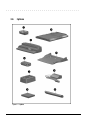
3.6 Options ...............................................................................................3-14
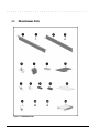
3.8 Miscellaneous Parts............................................................................3-16
3.8 Shipping Boxes ..................................................................................3-18
3.9 Documentation ...................................................................................3-19
Chapter 4
Removal and Replacement Preliminaries
4.1 Electrostatic Discharge ........................................................................4-1
4.1.1 Generating Static ..........................................................................4-1
4.1.2 Preventing Electrostatic Damage to Equipment ...........................4-2
4.1.3 Removing Batteries ......................................................................4-2
4.1.4 Preventing Damage to Drives .......................................................4-3
4.1.5 Grounding Methods ......................................................................4-3
4.1.6 Grounding Workstations...............................................................4-4
4.1.7 Grounding Equipment ..................................................................4-4
4.1.8 Recommended Materials and Equipment .....................................4-5
4.2 Service Considerations.........................................................................4-6
4.2.1 Tool Requirements........................................................................4-6
4.2.2 Cables and Connectors .................................................................4-6
4.3 Serial Number ......................................................................................4-6
vi Contents
. . . . . . . . . . . . . . . . . . . . . . . . . . . . . . . . . . . . .
Chapter 5
Removal and Replacement Procedures
5.1 Serial Number...................................................................................... 5-1
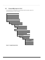
5.2 Disassembly Sequence Chart .............................................................. 5-2
5.3 Preparing the Computer for Disassembly............................................ 5-3
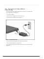
5.3.1 Disconnecting the AC Power and
External Diskette Drive Bay ................................................................. 5-4
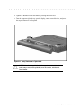
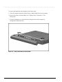
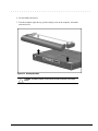
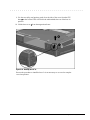
5.3.2 Undocking the Computer ............................................................. 5-5
5.3.3 Battery Packs.............................................................................. 5-11
5.3.4 DualBay Battery Pack and Devices .......................................... 5-13
5.3.4 Pointing Devices ........................................................................ 5-16
5.3.5 Hard Drive.................................................................................. 5-18
5.3.6 PC Card ...................................................................................... 5-19
5.4 External Computer Components ....................................................... 5-20
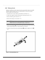
5.4.1 Computer Logo .......................................................................... 5-20
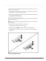
5.4.2 Computer Feet............................................................................ 5-21
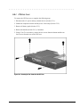
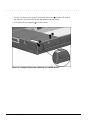
5.4.3 Handle ........................................................................................ 5-22
5.5 CPU Base Assembly ......................................................................... 5-26
5.5.1 Memory Cover ........................................................................... 5-27
5.5.2 Memory Boards.......................................................................... 5-28
5.5.3 Lithium Real Time Clock Battery.............................................. 5-30
5.5.4 CPU Base Cover ........................................................................ 5-31
5.5.5 Processor Shield and Board ...................................................... 5-34
5.5.6 CPU Cover and Keyboard Assembly........................................ 5-36
5.6 Display Assembly.............................................................................. 5-40
5.7 Clutch Assembly Components .......................................................... 5-44
5.7.1 Clutch Cover .............................................................................. 5-44
5.7.2 Clutches...................................................................................... 5-46
5.8 System Board Components ............................................................... 5-47
5.8.1 System Board ............................................................................. 5-47
5.8.2 Ensuring ESD Protection ........................................................... 5-52
5.8.3 Heatsink and Video Chip Heatpipe........................................... 5-53
5.9 Frame Components............................................................................ 5-56
5.9.1 Upper PCMCIA Door ................................................................ 5-56
5.9.2 Lower PCMCIA Door................................................................ 5-59
5.9.3 DualBay Eject Assembly ........................................................... 5-62
5.9.5 PCMCIA Assembly .................................................................. 5-64
5.9.6 PCMCIA Ejector Buttons .......................................................... 5-67
5.9.7 Display Ground Bracket............................................................. 5-69
Chapter 6
Specifications
6.1 Computer ............................................................................................. 6-2
6.2 Displays .............................................................................................. 6-3
6.3 Hard Drives ......................................................................................... 6-6
Contents vii
. . . . . . . . . . . . . . . . . . . . . . . . . . . . . . . . . . . . .
6.4 Diskette Drive ......................................................................................6-9
6.5 CD-ROM Drives ...............................................................................6-10
6.6 Battery Packs.....................................................................................6-13
6.7 Mobile CD Expansion Unit................................................................6-14
6.8 External Power Supplies ....................................................................6-15
6.9 System Interrupts ...............................................................................6-18
6.10 System DMA....................................................................................6-19
6.11 System I/O Address ........................................................................6-20
6.12 System Memory Map......................................................................6-22
Appendix A
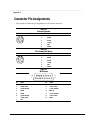
Connector Pin Assignments ...................................................................................A-1
Appendix B
Power Cord Set Requirements ..............................................................................B-1
3-Conductor Power Cord Set .................................................................... B-1
General Requirements .......................................................................... B-1
Country-Specific Requirements............................................................ B-2
Index................................................................................................................................... I-1
viii Contents
. . . . . . . . . . . . . . . . . . . . . . . . . . . . . . . . . . . . .
Preface
Preface
This Maintenance and Service Guide is a troubleshooting guide that can be used for
reference when servicing the Compaq Armada 4100 and 4200 Families of Personal
Computers. Additional information is available in the Service Quick Reference Guide
and in QuickFind.
Compaq Computer Corporation reserves the right to make changes to the Compaq
Armada 4100 and 4200 Families of Personal Computers without notice.
Symbols
The following symbols and words mark special messages throughout this guide:
!
WARNING: Text set off in this manner indicates that failure to follow directions in the
warning could result in bodily harm or loss of life.
CAUTION: Text set off in this manner indicates that failure to follow directions could
result in damage to equipment or loss of data.
IMPORTANT: Text set off in this manner presents clarifying information or specific
instructions.
NOTE: Text set off in this manner presents commentary, sidelights, or other points
of information.
Technician Notes
!
WARNING: Only authorized technicians trained by Compaq should attempt to repair
this equipment. All troubleshooting and repair procedures are detailed to allow only
subassembly/module level repair. Because of the complexity of the individual boards and
subassemblies, no one should attempt to make repairs at the component level or to
make modifications to any printed wiring board. Improper repairs can create a safety
hazard. Any indication of component replacement or printed wiring board modifications
may void any warranty or exchange allowances.
CAUTION: To properly ventilate your system, you must provide at least 3 inches
(7.62 cm) of clearance on the front and back of the computer.
!
WARNING: The computer is designed to be electrically grounded. To ensure proper
operation, plug the AC power cord into a properly grounded electrical outlet only.
Preface
xi
. . . . . . . . . . . . . . . . . . . . . . . . . . . . . . . . . . . . . .
Laser Safety
All Compaq systems, equipped with CD-ROM drives, comply with appropriate safety
standard including IEC 825. With specific regard to the laser, the equipment complies
with laser product performance standards set by government agencies as a Class 1 laser
product. It does not emit hazardous light; the beam is totally enclosed during all modes
of customer operation and maintenance.
CDRH Regulations
The Center for Devices and Radiological Health (CDRH) of the U.S. Food and Drug
Administration implemented regulations for laser products on August 2, 1976. These
regulations apply to laser products manufactured from August 1, 1976. Compliance is
mandatory for products marketed in the United States.
!
WARNING: Use of controls or adjustments or performance of procedures
other than those specified herein or in the CD ROM installation guide may
result in hazardous radiation exposure.
This system is classified as a CLASS 1 LASER PRODUCT. This label is located on the
outside of your system. A similar label also appears on the internal CD-ROM installed
in your system.
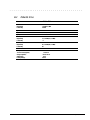
LASER INFO
Laser Type:
Wave Length:
Divergence Angle:
Output Power:
Polarization:
Numerical Aperture:
Semiconductor GaAIAs
780 +/- 35 nm
53.5 Degree +/- 1.5 Degree
Less than 0.2mW or 10,869 W•m-2sr-1
Circular
0.45 +/- 0.04
Only authorized technicians trained by Compaq should attempt to repair this
equipment. All troubleshooting and repair procedures are detailed to allow only
subassembly/module level repair. Because of the complexity of the individual boards
and subassemblies, no one should attempt to make repairs at the component level or to
make modifications to any printed wiring board. Improper repairs can create a safety
hazard.
xii
Preface
. . . . . . . . . . . . . . . . . . . . . . . . . . . . . . . . . . . . . .
Locating Additional Information
The following documentation is available to support the products:
■
Quick Setup
■
Reference Guide
■
Introducing Microsoft Windows 95
■
Compaq Service Quick Reference Guide
■
Service Training Guides
■
Compaq Service Advisories and Bulletins
■
Compaq QuickFind
■
Technical Reference Guide
Preface
xiii
. . . . . . . . . . . . . . . . . . . . . . . . . . . . . . . . . . . . .
Chapter 1
Product Description
1.1
Computer Features and Models
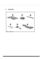
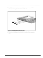
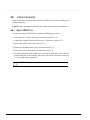
The Compaq Armada 4100 and 4200 Families are mobile notebook computers with
advanced modularity, processors, and video graphics. Both families provide fullfunction, Pentium-based notebook computers that allow desktop functionality and
connectivity through the use of an optional Mobile CD (MCD) Expansion Unit and a
convenience base.
The 4100 Family provides light weight multimedia models with up to 166-MHz
processors with MMx technology, 8- or 16-MB of system memory, hard drive capacity
up to 2.0 GB, and primary battery power from the handle battery.
The 4200 Family provides slimline models with 233- or 266-MHz processor, 32-MB of
system memory, hard drive capacity up to 4-GB, and primary battery power from the
modular battery pack in the DualBay.
This chapter describes the features of these computer models.
■
Compaq Armada 4100
■
Compaq Armada 4110 and 4110D
■
Compaq Armada 4115
■
Compaq Armada 4120 and 4120T
■
Compaq Armada 4125D and 4125T
■
Compaq Armada 4130T
■
Compaq Armada 4131T
■
Compaq Armada 4140T
■
Compaq Armada 4150 and 4150T
■
Compaq Armada 4160T
■
Compaq Armada 4160T Slimline
■
Compaq Armada 4210T
■
Compaq Armada 4220T
Product Description
1-1
. . . . . . . . . . . . . . . . . . . . . . . . . . . . . . . . . . . . .
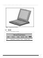
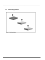
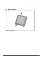
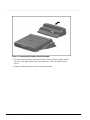
Figure 1-1. Compaq Armada 4100 and 4200
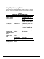
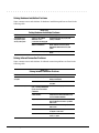
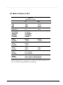
1.2
Models
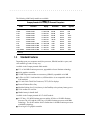
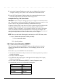
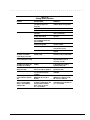
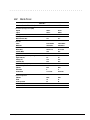
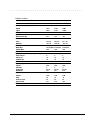
The following 4200 models are available:
Table 1-1
4200 Family of Personal Computers
Model
Processor
Display
Hard Drive
Cache
Memory/
Upgrade
4210T
233-MHz Pentium
12.1-inch CTFT
3.0-GB
256-KB (L2)
32/96
4220T
266-MHz Pentium
12.1-inch CTFT
4.0-GB
512-KB (L2)
32/96
1-2 Product Description
. . . . . . . . . . . . . . . . . . . . . . . . . . . . . . . . . . . . .
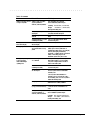
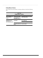
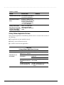
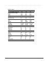
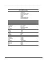
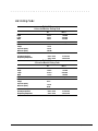
The following 4100 Family models are available:
Table 1-2
Compaq Armada 4100 Family of Personal Computers
Model
Processor
Display
Hard Drive
Memory/
Upgrade
Cache
4120
4125D
4120T
4120T
120-MHz Pentium
120-MHz Pentium
120-MHz Pentium
120-MHz Pentium
11.3-inch CSTN
11.3-inch CSTN
11.8-inch CTFT
11.8-inch CTFT
810-MB
810-MB
810-MB
810-MB
256-KB
256-KB
256-KB
256-KB
16/48*
8/40
8/40
16/48*
4125T
120-MHz Pentium
11.8-inch CTFT
810-MB
256-KB
16/48*
4130T
133-MHz Pentium
11.8-inch CTFT
1.08-GB
256-KB
16/48
4131T
4150
4150T
4160T
4160T Slimline
133-MHz Pentium
150-MHz Pentium w/ MMx
150-MHz Pentium w/ MMx
166-MHz Pentium w/ MMx
166-MHz Pentium w/ MMx
11.8-inch CTFT
12.1-inch CSTN
12.1-inch CTFT
12.1-inch CTFT
12.1-inch CTFT
1.4-GB
1.6-GB
1.6-GB
2.0-GB
2.0-GB
256-KB
256-KB
256-KB
256-KB
256-KB
16/48
16/80
16/80
16/80
16/80
* Japan only
1.3
Standard Features
Depending upon your computer model, the processor, DRAM, hard drive space, and
color monitor type and size may vary:
Available in the Compaq Armada 4200 models:
■
233- or 266-MHz Pentium processors, upgradable to future Pentium technology
■
64-bit graphics controller
■
32-MB of dynamic random access memory (DRAM), expandable to 96 MB
■
3-GB or 4-GB 2.5- inch hard drives (4-GB hard drive is not compatible with the
4100 modeles)
■
12.1-inch Color Thin Film Transistor (CTFT) SVGA displays
■
External Diskette Drive Bay
■
Modular Lithium Ion (Li-ion) battery in the DualBay as the primary battery power
■
32-bit cardbus PC card slot
■
Handle battery in handle shell
Available in the Compaq Armada 4131T-4160T models:
■
4131T has a 133-MHz Pentium procesor and the 4150 has a 150-MHz Pentium
processor.The 4150 and the 4150T have 150-MHz Pentium processors with MMx
technology. The 4160T and the 4160T slimline have 166-MHz Pentium processors
with MMx technology.
■
Cirrus logic LCD graphic controller
Product Description 1-3
. . . . . . . . . . . . . . . . . . . . . . . . . . . . . . . . . . . . .
■
16-MB of dynamic random access memory (DRAM), expandable to 40-, 48- or 80
MB
■
1.4-GB, 1.6-GB, and 2-GB hard drives
■
Lithium Ion (Li-ion) handle battery pack primary battery power
■
16-bit PC card system
Available in the Compaq Armada 4100-4130T models:
■
All models prior to and including the 4131T can be upgraded to a 133-MHz
Pentium processor by replacing the processor board.
■
75-, 100-, 120-, or 133-MHz Pentium processors.
■
8- or 16-MB of dynamic random access memory (DRAM), expandable to 72- or 80MB
■
630-MB, 810-MB, or 1.08-GB 2.5- inch hard drives
■
10.4-inch Color Super Twist Nematic (CSTN), 11.3-inch CSTN, or 11.8-inch Color
Thin Film Transistor (CTFT) SVGA displays
■
Lithium Ion (Li-ion) handle battery pack primary battery power
The following features are standard in both the Compaq Armada 4100 and 4200
Families:
■
NTSC/PAL TV video allows full screen, full motion digital video presentation with
interleaved synchronized stereo sound. MPEG accommodates full motion video in
the range of 24 frames per second (cinema quality) to 30 frames per second
(television quality).
■
IDE hard drive in the dedicated hard drive bay. Cable select technology is employed
for device 0/device 1 selection. The hard drive is secured in place with a pair of
screws
■
3.5-inch 1.44-MB diskette drive DualBay module supports a single diskette drive
■
Supports Lithium Ion (Li-ion) and Nickel Metal Hydride (NiMH) handle battery
packs
■
Sound Blaster−compatible audio controller with internal stereo speakers and internal
microphone
■
Full-size 101 key compatible keyboard including 12 function keys, 8 cursor control
keys, inverted-T cursor control keys, and embedded numeric keypad
■
Four user-programmable keys
■
Touchpad pointing device
■
Operates from an internal battery pack or an AC adapter that is compatible with
domestic or international power sources
■
Power management and security features
1-4 Product Description
. . . . . . . . . . . . . . . . . . . . . . . . . . . . . . . . . . . . .
■
Infrared interface for wireless communication with other IrDA-compliant devices at
data rates up to 115 kbaud or 4 mbps on the 4210T, 4220T, 4150, 4150T, 4160T,
and the 4160T Slimline models.
■
Two PCMCIA standard device slots that will accommodate two types I and II and
one type III PC Cards
■
120-pin expansion connector provides the interface to the Mobile CD Expansion
Unit (MCD) and the convenience base
■
Rear-panel ports provide connections for parallel and serial, video out,
keyboard/mouse, and IrDA compliant infrared devices
1.3.1
Software Fulfillment
Backup software may be ordered directly from Compaq Computer Corporation through
the Compaq Order Center. Both the model and serial numbers of the computer are
needed to identify the specific software available.
For technical questions about software for the computer, contact a Compaq Technical
Support Engineer. The model and serial numbers of the computer should be available
before making the call.
1.3.2
Security Features
The computer has the following security features:
■
Ability to secure the computer and MCD Expansion Unit to an immovable object
with an optional cable lock.
■
Ability to establish power-on and setup passwords and to disable ports and devices
from the Security menu in Computer Setup.
1.3.3
Power Management
The computer supports three power management modes:
■
Local Standby: The ability of individual subsystems to enter reduced power modes
after predetermined periods of inactivity.
■
Global Standby: The ability to place all subsystems in a reduced power mode after a
predetermined period of inactivity.
■
Hibernation: The ability to save the system configuration and user data to the hard
disk, for restoration at a later time.
■
ACPI Hardware Ready (Advanced Configuration and Power Interface): the 4200
Family models support the operation of hardware and software power specifications
to interface in a single system and be used as needed.
In addition, there are the OFF and ON states. In the OFF state, the computer appears to
be consuming no power; however, as long as there is a battery capable of supplying
current, some components will be powered up, performing housekeeping tasks and
Product Description 1-5
. . . . . . . . . . . . . . . . . . . . . . . . . . . . . . . . . . . . .
waiting to be awakened. In the ON state, all systems are powered up and the unit is
completely functional.
1.4
Options
The 4100 and 4200 Families support the following options:
■
MCD Expansion Unit
■
Convenience base (Passthrough and Ethernet models)
■
Memory expansion boards
■
Li-ion handle battery packs
■
Li-ion modular battery pack
■
Automobile Adapter
■
AC Adapter
■
External Battery Charger
■
PCMCIA modem
■
Trackball pointing device
■
AC power cords for international travelers
■
Display upgrades (4100 Family models only)
■
Hard drive upgrades (model dependent)
■
Processor upgrades (4100 Family models only)
■
External Battery Charger
■
External keyboards
■
External diskette drive bay
■
Compaq mouse
■
USB Cardbus PC card(4200 Family models only)
1.4.1
System Memory Options
The computer supports optional 4-, 8-, 16-, 32-MB or 64-MB memory board sets. The
memory boards are 70 ns Fast Page Mode DRAM SODIMMs, without parity. System
memory can be expanded to 40, 48, or 96-MB of DRAM depending on the model.
The 4210T and 4220T models can support standard EDO and FP memory upgrades.
Compaq does not offer EDO memory upgrade kits.
The system includes two DIMM slots that must be populated in pairs with DIMMs of
equal size and type. Either parity or non-parity DIMMs may be used, but parity
checking will not be enabled by the memory controller.
1-6 Product Description
. . . . . . . . . . . . . . . . . . . . . . . . . . . . . . . . . . . . .
1.4.2
Display Options
The 4100 Family models with 11.3-inch, 11.8-inch, or CSTN displays can be upgraded
to an 12.1-inch Color Thin Film Transistor (CTFT) SVGA display.
1.4.3
Secondary Cache
The 4200 Family models are equipped with 256-KB or 512-KB secondary (L2) cache
of write-back/write-through cache on the system I/O board.
Models 4110 through 4160T of the 4100 Family are equipped with 256-KB of writeback/write-through cache on the system I/O board.
1.4.4
Mobile CD Expansion Unit
The Mobile CD-ROM Expansion Unit provides the following multimedia capabilities:
■
CD-ROM drive
■
Integrated stereo speakers
■
Game port with MIDI support
■
Dedicated battery bay
The CD-ROM drive is available in the optional MCD Expansion unit. The drive
supports the following formats:
■
ISO-9660, the most common CD-ROM format
■
CD-ROM XA eXtended Architecture, a standard for storing multimedia information
■
Photo CD (Kodak's format for storing photographic images on CD-ROM)
1.4.5
Convenience Base
The convenience base provides the following added capabilities:
■
Pass-through ports (serial, parallel, and video)
■
Expansion features (mouse and keyboard ports, network support)
■
Five-degree tilt for the notebook keyboard
■
Charging of batteries in the system
■
Integrated Ethernet (available on models with Ethernet capability)
1.4.6
Mass Storage Options
A 4-GB hard drive is available as options for the 4210T. The 3-GB hard drive supports
both the 4100 and 4200 Family models. Only a single diskette drive may be used at any
one time with the computer. This drive may be used in the DualBay or externally with
an optional parallel cable.
Product Description 1-7
. . . . . . . . . . . . . . . . . . . . . . . . . . . . . . . . . . . . .
1.4.7
AC Adapter
The AC adapter supplies DC voltage to the system converter to operate and/or charge
the installed battery pack(s). The adapter provides sufficient power to charge each main
battery pack in 1.5 hours or less with the system off, or in 2.5 hours or less with the
system on. The AC adapter power specifications are presented in Chapter 6.
1.4.8
Automobile Adapter
The automobile adapter is used to charge the computer while traveling in an
automobile. The Automobile Adapter power specifications are presented in Chapter 6.
1.4.9
Lithium Ion Battery Pack
Lithium Ion (Li-ion) battery packs offer superior performance over nickel metal
hydride batteries. NiMH batteries are not recommended. Li-ion batteries weigh
approximately half as much as the NiMH battery packs and are compatible with the
External Battery Charger and its charging options. They are available in both battery
handle and modular bay forms.
1.4.10 External Battery Charger
The External Battery charger has the following features:
■
Two battery charge slots
■
Accepts Li-ion handle and modular batteries
■
Fast charges one battery in 1.5 hours
■
Fast charges two batteries in 3 hours
1.4.11 External Keyboards
The following external full-size keyboards are supported:
■
Enhanced III keyboard
■
SpaceSaver keyboard
■
Alternative design keyboard
1.4.12 External Monitors
The following external monitors are supported:
■
QVision 172 Color Monitor
■
151 FS Color Monitor
■
171 FS Color Monitor
■
V50 Color
■
V70 Color
1-8 Product Description
. . . . . . . . . . . . . . . . . . . . . . . . . . . . . . . . . . . . .
■
P50 Color
■
P70 Color
■
P110 Color
■
P1610 Color
■
TFT500 Flat Panel
1.4.13 Compaq Mouse
The computer supports a PS/2 mouse or other external pointing device.
1.4.14 Trackball Pointing Device
The modular trackball provides an effective alternate to the touchpad or an external
mouse when the machine is used in either a portable or desktop environment.
Product Description 1-9
. . . . . . . . . . . . . . . . . . . . . . . . . . . . . . . . . . . . .
1.5
External Computer Components
The external computer components are illustrated and described in this section.
1.5.1
Front and Left Side Components
The front and left side external components are shown in the following figure and
identified in this section:
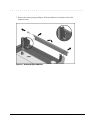
1
Cable lock provision
2
Hard drive compartment
3
PC Card slots
4
PC Card eject buttons
5
Audio connectors
6
Display latch
Figure 1-2. Front and Left Side Components
1-10 Product Description
. . . . . . . . . . . . . . . . . . . . . . . . . . . . . . . . . . . . .
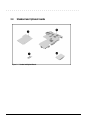
1.5.2
Front and Right Side Components
The front and right side computer components are shown and identified in this section.
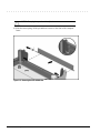
1
Pointing device
2
DualBay module
3
Speaker
4
DualBay eject button
5
AC power connector
6
User programmable keys
Figure 1-3. Front and Right Side Components
Product Description 1-11
. . . . . . . . . . . . . . . . . . . . . . . . . . . . . . . . . . . . .
1.5.3
Rear Components
The front and right side computer components are shown and identified in this section.
1
Keyboard/mouse connector
2
Parallel connector
3
Serial connector
4
Infrared lens (IrDA compliant)
5
External monitor connector
6
NTSC/PAL video
7
Status panel indicator lights
8
Handle
Figure 1-4. Rear Components
1-12 Product Description
. . . . . . . . . . . . . . . . . . . . . . . . . . . . . . . . . . . . .
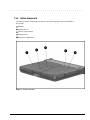
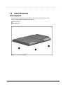
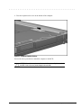
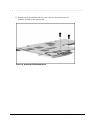
1.5.4
Bottom Components
The bottom external components are shown in the following figure and are identified in
this section:
1
DualBay
2
Pointing device
3
Memory compartment
4
Expansion slot
5
Hard drive compartment
Figure 1-5. Bottom Components
Product Description 1-13
. . . . . . . . . . . . . . . . . . . . . . . . . . . . . . . . . . . . .
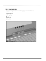
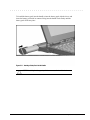
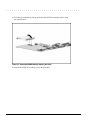
1.5.5
Status Panel Lights
The status panel lights are shown in the following figure and are identified in this
section:
1
Power/Suspend
2
Battery charge
3
Caps Lock
4
Scroll Lock
5
Num Lock
Figure 1-6. Status Panel Lights
1-14 Product Description
. . . . . . . . . . . . . . . . . . . . . . . . . . . . . . . . . . . . .
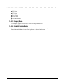
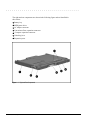
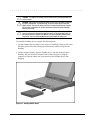
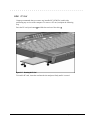
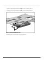
1.6 Mobile CD Expansion
Unit Components
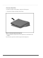
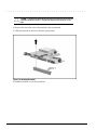
The front and left components of the Mobile CD Expansion Unit are shown in the
following figure and are identified in this section:
1
Stereo speakers
2
CD-ROM drive
Figure 1-7. Left and Front Components
Product Description 1-15
. . . . . . . . . . . . . . . . . . . . . . . . . . . . . . . . . . . . .
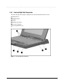
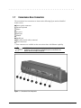
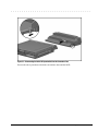
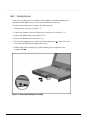
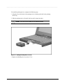
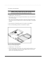
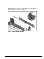
The right and rear components are shown in the following figure and are identified in
this section:
1
Battery bay
2
MIDI/game device
3
AC adapter connector
4
Convenience Base expansion connector
5
Computer expansion connector
6
Unlocking lever
7
Expansion posts
Figure 1-8. Right and Rear Components
1-16 Product Description
. . . . . . . . . . . . . . . . . . . . . . . . . . . . . . . . . . . . .
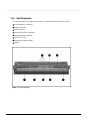
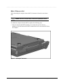
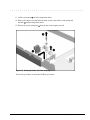
1.7
Convenience Base Connectors
The convenience base connectors are shown in the following figure and are identified
in this section:
Stereo speaker connector
External keyboard
3 Mouse
4 AC power
5 Serial port
6 Monitor
7 Parallel port
8 BNC (thin coaxial cable) connector*
9 RJ-45 connector*
* These connectors are available on the convenience base with Ethernet capability.
1
2
!
WARNING: To reduce the risk of electrical shock, fire or damage to the
equipment, do not plug telecommunications/telephone connectors into the
Network Interface Card (NIC) receptacles.
Figure 1-9. Convenience Base Components
Product Description 1-17
. . . . . . . . . . . . . . . . . . . . . . . . . . . . . . . . . . . . .
1.8
Design Overview - Computer
This section presents a design overview of the 4100 and 4200 Families. The overview
is limited to field replaceable parts. All replacement parts are listed in Chapter 3.
Removal and replacement procedures are presented in Chapter 5.
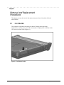
The computer is a traditional clamshell design with a display unit attached to a system
unit. The computer opens to reveal a backlighted LCD display and a full-sized
keyboard. The display is designed for a continuously adjustable tilt angle. The system
unit houses the keyboard, I/O ports, operator controls and indicators, and DualBay
devices.
1.8.1
System Unit
The system unit contains the following field-replaceable parts:
■
System board
■
Processor board
■
Display assembly
■
CPU/keyboard cover
■
Internal microphone
■
Optional memory expansion boards
■
Lithium Real Time clock battery
■
Hard drive
■
Diskette drive
■
Handle
■
Pointing device
■
CPU base cover
■
PCMCIA assembly
1.8.2
System Board
The Compaq Armada system electronics are integrated on two printed circuit
assemblies; the system board and the processor board. The 4100 system boards are not
compatible with the 4200 Family system boards. Similarly, the 4200 system boards are
not compatible with the 4100 Family.
1-18 Product Description
. . . . . . . . . . . . . . . . . . . . . . . . . . . . . . . . . . . . .
1.8.3
Processor Board
Prior to the 4150 model, there are two processor board PCAs with either 8-MB or 16-MB of
memory and with a level-2 cache populating the models with 100-, 120- and 133-MHz
processors. The MMX processor on the 4150 , 4150T, and 4160T are P55CLM processors
operating at 150 or 166 MHz. These processors are not compatible with 4131T, 4130T,
4120T, 4120, 4110, and 4100 models.
In each of the 4100 and 4200 systems there are two processor board PCAs with a level2 cache. The processor board contains the CPU, the OPTi 82C557 system Controller,
the OPTi 82C556 data buffer controller, and, if populated on the PCB, cache data
RAM. Also mounted on the processor board is an electronic temperature sensor that
interfaces to the system through the I2C bus.
The 4210T and 4220T processor boards include the 233- and 266-MHz MMX
processors and the MTXC controller, part of the Intel 430TX mobile chipset. The 4200
Family processor boards also include the electronic sensor that interfaces to the system
through the I2C bus.
1.8.4
Processor
The P54LM and the P55CLM Intel Pentium processors are fully compatible with the entire
installed base of applications for DOS, Windows, and OS/2, branch predition, and separate
code and data caches all provide increased performance over previous x86 processors.
Reduced voltage operation and enhanced SL power management features provide significant
power savings over other Pentium versions.
For the 4200 Family, the 233 MHz CPU core runs on a 1.8 V supply. The 266 MHz CPU core
runs on a 2.0 V supply. The interface for the 4200 Family is 2.5 V to 3.3 V.
For the 4100 Family, the CPU core runs on a 2.9V supply for lower power operation, while
the I/O buffers are powered at 3.3V for compatibility with the rest of the system.
1.8.5
System Memory
See Tables 1-1 and 1-2 for the system memory contained on models for the 4100 and
4200 Families. Up to 96-MB of expansion memory is available. Base memory is
onboard memory built into the system I/O board. Expansion memory consists of
memory expansion board kits available as user installable options.
1.8.6
Cache
The 4200 Family models have 256-KB or 512-KB of cache data RAM and 64-KB of
cache tag RAM if populated on the PCB are mounted on the processor module.
The 4110-4160T models have 256-KB of cache data RAM and 32-KB of cache tag
RAM if populated on the PCB are mounted on the processor module.
Product Description 1-19
. . . . . . . . . . . . . . . . . . . . . . . . . . . . . . . . . . . . .
1.8.7
Local Bus Video
The standard Compaq Armada video subsystem consists of:
■
An internal LCD display.
■
One Megabyte frame buffer (Two Megabyte frame buffer for the 42210T and
4220T)
■
An inverter to supply AC power to the LCD back-light system
■
A standard external VGA connector for use with CRTs and other VGA compatible
displays
■
32-KB of video ROM (44KB of video ROM for the 4210T aand 4220T)
■
NTSC/PAL encoder
1-20 Product Description
. . . . . . . . . . . . . . . . . . . . . . . . . . . . . . . . . . . . .
Chapter 2
Troubleshooting
This chapter contains troubleshooting information for the computer and the
convenience base. The basic steps in troubleshooting the computer include:
1. Completing the preliminary steps listed in Section 2.1.
2. Running the Power-On Self-Test (POST) as described in Section 2.2.
2. Running Computer Setup as described in Section 2.5
4. Running the Computer Checkup (TEST) as described in Section 2.5.
5. Performing the recommended actions described in the diagnostic tables in Section
2.6 if you are unable to exercise POST or Computer Checkup or if the problem
persists after running POST and Computer Checkup.
Follow these guidelines when troubleshooting:
■
Complete the recommended actions in the order in which they are given.
■
Repeat POST and Computer Checkup after each recommended action until the
problem is resolved and the error message does not return.
■
Once the problem is resolved, do not complete the remaining recommended actions.
■
Refer to Chapter 5 for any removal and replacement procedures.
■
If the problem is intermittent, check the computer or convenience base several times
to verify that the problem is solved.
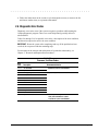
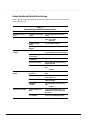
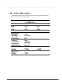
Use the following table for quick reference to troubleshooting information:
If You Want To:
Run:
Check for POST error messages
POST
Check that computer components are recognized and
running properly
Computer Checkup (TEST) under Compaq
Utilities
View information about the computer and installed or
connected devices
View System Information
(INSPECT)under Compaq Utilities
Perform any of the following:
Check the system configuration
Set the system power management
parameters
Return the system to its original
configuration
Check system configuration of installed devices
Computer Setup
Troubleshooting
2-1
. . . . . . . . . . . . . . . . . . . . . . . . . . . . . . . . . . . . .
2.1 Preliminary Steps
IMPORTANT: Use AC Power when running POST, Computer Setup, or Computer
Checkup. A low-battery condition could initiate Suspend or Hibernation and interrupt
the test.
Before running POST and Computer Checkup, complete the following steps:
1. Obtain established passwords. If you must clear the passwords, go to Section 2.2.
2. Ensure that the hard drive is installed in the computer.
2. Ensure that the battery pack is installed in the computer and the AC power is
connected to the computer and plugged into an AC power source.
4. Turn on the computer.
5. If a power-on password has been established, type the password and press Enter.
NOTE: The key icon appears on the display when the computer is turned on to indicate
that QuickLock/QuickBlank has been initiated. Type the power-on password to
exit QuickLock/QuickBlank. If the password is unknown, it must be cleared (see
Section 2.2).
6. Run Computer Setup (Section 2.5).
7. Use the Hotkeys to adjust the contrast (Fn+F9) and brightness (Fn+F10) to the center
of their ranges and leave the display open. On models with color TFT displays,
contrast is not applicable.
8. Turn off the computer and all external devices.
9. Disconnect any external devices that you do not want to test. If you want to use the
printer to log error messages, leave it connected to the computer.
NOTE: If a problem only occurs when an external device is connected to the computer,
the problem could be with the external device or its cable. Isolate the problem by
running POST with and without the external device connected.
10. Use Advanced Diagnostics and loopback plugs in the serial and parallel connectors
if you plan to test these ports. You may run Advanced Diagnostics from the hard
drive or from a diskette.
If you are running Diagnostics from the hard drive, complete the following steps:
a. Turn on or restart the computer.
b. Press F10 when the cursor appears in the upper right corner of the screen. If you
do not press F10 in time, restart the computer and try again. The Welcome screen
appears.
2-2
Troubleshooting
. . . . . . . . . . . . . . . . . . . . . . . . . . . . . . . . . . . . .
If you are running Diagnostics from a diskette, complete the following steps:
a. Insert the Diagnostics diskette into the diskette drive and turn on the computer.
b. At the Welcome Screen, press Enter to accept OK.
c. Select Computer Checkup (TEST).
d. Select Prompted Diagnostics after "Identifying System Hardware" completes.
e. Select Interactive Testing and follow the displayed instructions.
Refer to Chapter 3 for the description and spare part number of the loopback plugs.
After completing the preliminary steps, run POST (Section 2.3) and Computer Checkup
(Section 2.5).
2.2 Clearing the Power-On and Setup Passwords
The power-on password prevents use of the computer until the password is entered. The
setup password prevents unauthorized changes to Computer Setup. To clear the
passwords, you must remove all power from the system board. If you do not know the
passwords, use the following procedure to clear the password:
1. Remove all battery packs from the battery bay and DualBay, if applicable.
2. Disconnect the AC power.
2. Remove the real time clock battery.
4. Wait five minutes.
5. Reconnect the AC power.
6. Restart the computer. During the Power-On Self Test (POST), a "162 System
Options not Set" message appears. (See Section 2.4 for additional POST error
messages).
7. Shut down the computer, then turn off the power again.
8. Replace the real time clock battery.
9. Install the battery pack(s).
10. Proceed with the troubleshooting procedures.
Troubleshooting
2-3
. . . . . . . . . . . . . . . . . . . . . . . . . . . . . . . . . . . . .
2.3 Power-On Self Test (POST)
The Power-On Self-Test (POST) is a series of tests that run every time the computer is turned on. POST
verifies that the system is configured and functioning properly
To run POST, complete the following steps:
1. Complete the preliminary steps. (Section 2.1).
2. Turn on the computer.
If POST does not detect any errors, the computer beeps once or twice to indicate that
POST has run successfully and boots from the hard drive or from a bootable diskette if
one is installed in the diskette drive.
2.4 POST Error Messages
This section contains typical error messages that may occur during the power-on selftest (POST).
If you receive an error message read the description and follow the recommended
action or run Computer Checkup from the Diagnostics diskette. Information about
running Computer Checkup is presented later in this chapter.
If POST detects an error, one of the following events occurs:
■
A message with the prefix "WARNING" appears informing you where the error
occurred. The system pauses until you press F1 to continue.
■
A message with the prefix "FATAL" appears informing you where the error
occurred. After the message, the system emits a series of audible beeps. The system
then stops.
■
The system emits a series of audible beeps. The system then stops.
Warning messages indicate a potential problem exists such as a system configuration
error. When F1 is pressed, the system should resume. You should be able to correct
problems that produce WARNING messages.
IMPORTANT: When a WARNING message includes the prompt to "RUN SCU," run
Computer Setup. (Computer Setup replaces the SCU utility.)
Fatal errors emit a beep and may display a FATAL message. Fatal errors indicate
severe problems, such as a hardware failure. Fatal errors do not allow the system to
resume. Some of the fatal error beep codes are listed at the end of this section.
2-4
Troubleshooting
. . . . . . . . . . . . . . . . . . . . . . . . . . . . . . . . . . . . .
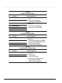
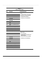
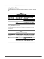
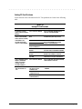
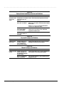
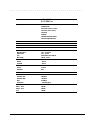
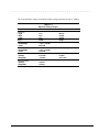
Table 2-1
Warning Messages
Message
Description
Clock not ticking correctly
The real-time clock is not ticking. Replace the real time clock
CMOS checksum invalid, run SCU
CMOS RAM information has been corrupted and needs to be
reinitialized by running Computer Setup.
CMOS failure, run SCU
CMOS RAM has lost power and needs to be reinitialized by running
Computer Setup.
Floppy controller failed
The diskette drive controller failed to respond to the reset
command. Power - down the system and check all appropriate
connections. If the diskette drive controller continues to fail, you
may need to replace the system board.
Floppy disk track 0 failed
The diskette drive cannot read track 0 of the diskette in the drive.
Try another diskette. If the problem persists, you may need to
replace the diskette drive.
Floppy information invalid, run SCU
The drive parameters stored in CMOS RAM do not match the
diskette drives detected in the system. Run Computer Setup.
Hard disk controller error
The hard drive controller failed to respond to the reset command.
Check the drive parameters. Power down the system and check all
appropriate connections.
Hardware info does not match video
card, run SCU
The video adapter type specified in CMOS RAM does not match the
installed hardware. Run Computer Setup.
Keyboard controller failure
The keyboard failed the self-test command. Replace the keyboard.
Keyboard failure
The keyboard failed to respond to the RESET ID command.
Press F1.
No interrupts from Timer 0
The periodic timer interrupt is not occurring. Press F1.
RAM parity error at location xxxx
A RAM parity error occurred at the specified (hex) location.
Press F1.
ROM at xxxx (LENGTH yyyy) with
nonzero checksum (zz)
An illegal adapter ROM was located at the specified address. An
external adapter (such as a video card) may be causing the conflict.
Run Computer Setup.
Time/Date corrupt - run SCU
The time and date stored in the real time clock have been
corrupted, possibly by a power loss. Run Computer Setup.
Unexpected amount of memory,
run SCU
The amount of memory detected by POST does not match the
amount specified in CMOS RAM. Run Computer Setup.
Hard disk xx failure (or error)
A failure or an error occurred when trying to access the hard drive.
Press F1 and continue.
Troubleshooting
2-5
. . . . . . . . . . . . . . . . . . . . . . . . . . . . . . . . . . . . .
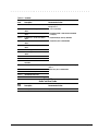
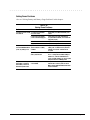
Table 2-2
Fatal Error Messages
Message
Description
Beep Code
CMOS RAM test failed
A walking bit test of CMOS RAM location 0E (Hex) - 3
3F (Hex) failed.
DMA controller faulty
A sequential read/write of the transfer count and
transfer address registers within the primary and
secondary DMA controllers failed.
4
Faulty DMA page registers
A walking bit read/write of the 16 DMA controller
page registers starting at location 80 Hex failed.
0
Faulty refresh circuits
A continuous read/write test of port 61h found that
bit 4 (Refresh Detect) failed to toggle within an
allotted amount of time.
1
Interrupt controller failed
A sequential read/write of various Interrupt
Controller registers failed.
5
ROM checksum incorrect
A checksum of the ROM BIOS does not match the
byte value at F000:FFFF.
2
RAM error at location xxxx
RAM error occurred during memory test.
None
Parity error at unknown location
Parity error occurred.
None
The following table lists some of the Fatal Error beep codes, along with the beep
sequence (short, long, pause) and the meaning of the beeps.
Table 2-3
Fatal Error Beep Codes
Beep Code Beep Sequence
Explanation
Remedy
0
S-S-S-P-S-S-L-P
The DMA page registers are
faulty.
Replace system board.
1
S-S-S-P-S-L-S-P
The refresh circuitry is faulty.
Replace system board.
2
S-S-S-P-S-L-L-P
The ROM checksum is incorrect.
1. Flash the ROM.
2.Replace system board.
3
S-S-S-P-L-S-S-P
The CMOS RAM test failed.
Replace system board.
4
S-S-S-P-L-S-L-P
The DMA controller is faulty.
Replace system board.
5
S-S-S-P-L-L-S-P
The interrupt controller failed.
Replace system board.
6
S-S-S-P-L-L-L-P
The keyboard controller failed.
Replace system board.
7
S-S-L-P-S-S-S-P
Graphics adapter is faulty.
Replace system board.
8
S-S-L-P-S-S-L-P
Internal RAM is faulty.
Replace processor board.
S = Short, L = Long, P = Pause
2-6
Troubleshooting
. . . . . . . . . . . . . . . . . . . . . . . . . . . . . . . . . . . . .
2.5 Compaq Utilities
Run the Compaq Utilities to view or test system information and installed or connected devices. Run
Compaq Utilities from either the computer hard drive or from diskette.
If running Compaq Utilities from a diskette, note the following:
Use version 10.13c or later.
You will not be able to make a utilities diskette.
Use the Computer Setup diskette to run Computer Setup.
The Utilities menu includes the following:
Computer Setup
Computer Checkup (TEST)
View System Information (INSPECT)
Create Diagnostics diskette (hard drive only)
Manage Diagnostics Partition (diskette only)
If the problem persists, call for support. Follow these steps to prepare for the support call:
1. Run Computer Checkup and save the device list to a file and print or save the log of errors.
2. Run the View System Information (INSPECT) utility and print or save that information.
2. Have the files or the printed information available when calling for support.
2.5.1 Running Computer Setup
Computer Setup contains a group of utilities that give you an overall picture of the
computer’s hardware configuration and aid in troubleshooting. Use these utilities to set
custom features, such as security options, power conservation levels, and startup
preferences.
A computer running Windows 95 automatically recognizes and configures the system
for new devices. However, if there is a configuration problem, or you want to view or
reset configuration settings, use Computer Setup.
Computer Setup provides two methods to view the computer’s configuration - by type
or connection. The default method for viewing Computer Setup is by type.
Troubleshooting
2-7
. . . . . . . . . . . . . . . . . . . . . . . . . . . . . . . . . . . . .
Categories by type include:
System Features—security, power, boot management
Communication—ports, modem, other communication devices
Storage—storage-related devices such as hard drive or diskette
Input Devices—keyboard, mouse, and other input devices
Network—Network adapter, or other network-related devices (Available only when
docked or when PC Card is installed
Audio—sound properties and audio device settings
Video—monitor video device resources
Other devices—devices that could not be categorized
Categories by connection include:
System Features—security, power, boot management
System Devices—keyboard, mouse, parallel and serial ports
ISA—ISA bus and related devices
PCI—PCI bus and connected devices
PC Card (PCMCIA) —PC Card bus and PC Card devices
2.5.2 Running Computer Checkup (TEST)
Computer Checkup (TEST) determines whether the various computer components and
devices are recognized by the system and are functioning properly. You can display,
print, or save the information generated by Computer Checkup.
Computer Checkup is installed on the hard drive. If the hard drive is nonfunctional, you
can run it from a diskette.
NOTE: It is recommended that you make diskette copies of Computer Checkup and
keep them available for future needs. A current copy can be obtained from the Compaq
Customer Support Center.
2-8
Troubleshooting
. . . . . . . . . . . . . . . . . . . . . . . . . . . . . . . . . . . . .
Computer Checkup
To run Computer Checkup from the hard drive, complete the following steps:
1. Close all applications and shut down the computer.
2. Turn off the computer.
2. Turn on the computer.
4. When the cursor moves to the right side of the screen, press F10.
A Welcome Screen is displayed that is followed by the Compaq Utilities main menu.
5. From the Compaq Utilities main menu, select Computer Checkup (TEST).
A diagnostics menu is displayed.
6. Select the option to view the device list.
A list of the installed hardware devices is displayed.
NOTE: Computer Checkup does not detect all non-Compaq devices.
7. Verify that Computer Checkup correctly detected the installed devices.
If the list is correct, select OK. The Computer Checkup option menu is displayed
again.
If the list is incorrect, verify that the new devices are installed properly.
8. Select one of the following from the diagnostics menu:
■
Quick Check Diagnostics. Runs a quick, general test on each device with a
minimal number of prompts. If errors occur, they display when the testing is
complete. You cannot print or save the error messages.
■
Automatic Diagnostics. Runs an unattended, maximum testing of each device
with minimal prompts. You can choose how many times to run the tests, to stop
on errors, or to print or save a log of errors.
■
Prompted Diagnostics. Allows maximum control over testing the devices. You
can choose attended or unattended testing, decide to stop on errors, or choose to
print or save a log of errors.
9. Follow the instructions on the screen as the devices are tested. When testing is
complete, the Diagnostics menu appears.
10. Exit the Diagnostics menu.
NOTE: Exiting the Compaq Utilities menu restarts the computer and saves the
changes.
Troubleshooting
2-9
. . . . . . . . . . . . . . . . . . . . . . . . . . . . . . . . . . . . .
11. Look up the Computer Checkup error codes that were displayed by referring to
"Computer Checkup (TEST) Error Codes" and take the recommended action.
12. Rerun POST and Computer Checkup, taking the recommended actions in given
order until the problem is solved and no error messages occur.
Computer Checkup (TEST) Error Codes
IMPORTANT: Rerun Computer Checkup each time you complete a recommended action
step. If the problem is resolved when POST and Computer Checkup are rerun (i.e., with
no error codes) do not perform the remaining recommended action steps.
Computer Checkup (TEST) error codes occur if the system recognizes a problem while
running Computer Checkup. These error codes help identify possible defective
assemblies. Tables 2-4 through 2-14 list Computer Checkup error codes, a description
of the error condition, and the recommended action for resolving the condition. For
removal and replacement procedures for the computer, refer to Chapter 7. For removal
and replacement procedures for the convenience base, refer to Chapter 8.
NOTE: The error codes in the following tables are listed in an AYE-XX format, where:
A or AA = Number that represents the faulty assembly.
Y = Test or action that failed.
XX = Specific problem.
2.5.3 View System Information (INSPECT)
The View System Information (INSPECT) utility provides information about the
computer and installed or connected devices. You can display, print, or save the
information.
Follow these steps to run INSPECT from the hard drive:
1. Turn on the external devices that you want to test. Connect the printer if you want to
print the information.
2. Turn on or restart the computer.
2. Press F10 when the prompt appears in the right side of the display. The Compaq
Utilities screen appears.
4. Select View System Information (INSPECT) from the Diagnostics menu.
5. Select the item you want to view from the following list:
2-10
System
Memory
ROM
Audio
Keyboard
Operating system
System ports
System files
System storage
Windows files
Graphics
Miscellaneous
Troubleshooting
. . . . . . . . . . . . . . . . . . . . . . . . . . . . . . . . . . . . .
6. Follow the instructions on the screen to cycle through the screens, to return to the list
and choose another item, or to print the information.
2.6 Diagnostic Error Codes
Diagnostic error codes occur if the system recognizes a problem while running the
Compaq Diagnostic program. These error codes help identify possibly defective
subassemblies.
Tables 2-4 through 2-14 list possible error codes, a description of the error condition,
and the action required to resolve the error condition.
IMPORTANT: Retest the system after completing each step. If the problem has been
resolved, do not proceed with the remaining steps.
For assistance in the removal and replacement of a particular subassembly, see
Chapter 5, "Removal and Replacement Procedures."
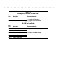
Table 2-4
Processor Test Error Codes
Error
Code
Description
101-xx
CPU test failed
102-xx
Coprocessor or Weitek Error
102-xx
DMA page registers test failed
104-xx
Interrupt controller master test failed
105-xx
Port 61 error
106-xx
Keyboard controller self-test failed
107-xx
CMOS RAM test failed
108-xx
CMOS interrupt test failed
109-xx
CMOS clock test failed
110-xx
Programmable timer load data test failed
112-xx
Protected mode test failed
114-01
Speaker test failed
Recommended Action
Replace the processor board and retest.
Replace the system board and retest.
1. Check system configuration.
2.Verify cable connections to speaker.
2. Replace the system board and retest.
Troubleshooting
2-11
. . . . . . . . . . . . . . . . . . . . . . . . . . . . . . . . . . . . .
Table 2-5
Memory Test Error Codes
Error
Code
Description
200-xx
Memory machine ID test failed
202-xx
Memory system ROM checksum failed
202-xx
Write/Read test failed
The following steps apply to error codes 202-xx
through 215-xx:
204-xx
Address test failed
1.Remove the memory board and retest.
211-xx
Random pattern test failed
2 Install a new memory board and retest.
214-xx
Noise test failed
215-xx
Random address test failed
Recommended Action
The following steps apply to error codes 200-xx and
202-xx:
1.Flash the system ROM and retest.
2.Replace the system board and retest.
Table 2-6
Keyboard Test Error Codes
Error
Code
Description
300-xx
Failed ID Test
The following steps apply to error codes 300-xx
through 304-xx :
301-xx
Failed Selftest/Interface Test
1.Check the keyboard connection. If disconnected,
turn off the computer and connect the keyboard.
302-xx
Failed Individual Key Test
2. Replace the keyboard and retest.
304-xx
Failed Keyboard Repeat Test
2. Replace the system board and retest.
Recommended Action
Table 2-7
Parallel Printer Test Error Codes
Error
Code
Description
401-xx
Printer failed or not connected
402-xx
Failed Port Test
1. Connect the printer.
402-xx
Printer pattern test failed
2. Check power to the printer.
Recommended Action
The following steps apply to error codes 401-xx
through 402-xx :
2. Install the loop-back connector and retest.
4. Check port and IRQ configuration.
5. Replace the system board and retest.
2-12
Troubleshooting
. . . . . . . . . . . . . . . . . . . . . . . . . . . . . . . . . . . . .
Table 2-8
Diskette Drive Test
Error
Code
600-xx
Description
Recommended Action
601-xx
602-xx
Diskette ID drive types test
failed
Diskette format failed
Diskette read test failed
602-xx
604-xx
605-xx
606-xx
609-xx
610-xx
697-xx
698-xx
699-xx
Diskette write, read, compare test failed
Diskette random read test failed
Diskette ID media failed
Diskette speed test failed
Diskette reset controller test failed
Diskette change line test failed
Diskette type error
Diskette drive speed not within limits
Diskette drive/media ID error
The following steps apply to error codes 600-xx
through 698-xx:
1.Replace the diskette media and retest.
2.Check and/or replace the diskette power and signal
cables and retest.
2.Replace the diskette drive and retest.
4.Replace the system board and retest.
Run Computer Setup.
Table 2-9
Serial Test Error Codes
Error
Code
Description
1101-xx
Serial port test failed
Recommended Action
1.Check port configuration.
2.Replace the system board and retest.
Table 2-10
Hard Drive Test Error Codes
Error
Code
Description
1701-xx
Hard drive format test failed
1702-xx
1702-xx
Hard drive read test failed
Hard drive write/read/compare test
failed
1704-xx
Hard drive random seek test failed
1705-xx
Hard drive controller test failed
1706-xx
Hard drive ready test failed
1707-xx
Hard drive recalibration test failed
1708-xx
Hard drive format bad track test failed
1709-xx
Hard drive reset controller test failed
1710-xx
Hard drive park head test failed
1715-xx
Hard drive head select test failed
1716-xx
Hard drive conditional format test failed
1717-xx
Hard drive ECC* test failed
1719-xx
Hard drive power mode test failed
1724-xx
Network preparation test failed
1736-xx
Drive monitoring test failed
* ECC = Error Correction Code
Recommended Action
The following steps apply to error codes 1701-xx
through 1736-xx :
1.Run Computer Setup.
2.Replace the hard drive and retest.
2.Replace the system board and retest.
Troubleshooting
2-13
. . . . . . . . . . . . . . . . . . . . . . . . . . . . . . . . . . . . .
Table 2-11
Video Test Error Codes
Error
Code
Description
501-xx
Video controller test failed
The following apply to error codes 501-xx through
516-xx:
502-xx
Video memory test failed
1. Connect and external monitor and retest.
502-xx
Video attribute test failed
2.Replace the LED status board and retest.
504-xx
Video character set test failed
2. Replace the display and retest.
505-xx
Video 80 × 25 mode 9 × 14 character
cell test failed
Video 80 × 25 mode 8 × 8 character
cell test failed
Video 40 × 25 mode test failed
4. Replace the system board and retest.
506-xx
507-xx
508-xx
509-xx
510-xx
Recommended Action
Video 320 × 200 mode color set 0 test
failed
Video 320 × 200 mode color set 1 test
failed
Video 640 × 200 mode test failed
511-xx
Video screen memory page test failed
512-xx
Video gray scale test failed
514-xx
Video white screen test failed
516-xx
Video noise pattern test failed
2402-xx
Video memory test failed
The following steps apply to error codes 2402-xx
through 2456-xx:
2402-xx
Video attribute test failed
1. Run Computer Setup.
2404-xx
Video character set test failed
2.Disconnect external monitor and test with
internal LCD display.
2405-xx
Video 80 × 25 mode 9 × 14 character
cell test failed
Video 80 × 25 mode 8 × 8 character
cell test failed
2.Replace the display assembly and retest.
2406-xx
4. Replace the system board and retest.
2408-xx
2409-xx
2410-xx
Video 320 × 200 mode color set 1 test
failed
Video 640 × 200 mode test failed
2411-xx
Video screen memory page test failed
2412-xx
Video gray scale test failed
2414-xx
Video white screen test failed
2416-xx
Video noise pattern test failed
2418-xx
ECG/VGC memory test failed
Continued
2-14
Troubleshooting
. . . . . . . . . . . . . . . . . . . . . . . . . . . . . . . . . . . . .
Table 2-11 Continued
Error
Code
Description
Recommended Action
2419-xx
ECG/VGC ROM checksum test failed
The following steps apply to error codes 2402-xx
through 2456-xx:
2421-xx
ECG/VGC 640 × 200 graphics mode test
failed
1. Run Computer Setup.
2422-xx
ECG/VGC 640 × 350 16 color set test
failed
2.Disconnect external monitor and test with internal
LCD display.
2422-xx
ECG/VGC 640 × 350 64 color set test
failed
2. Replace the display assembly and retest.
2424-xx
ECG/VGC monochrome text mode test
failed
4. Replace the system board and retest.
2425-xx
ECG/VGC monochrome graphics mode test
failed
2431-xx
640 × 480 graphics test failure
2432-xx
320 × 200 graphics (256 color mode) test
failure
2448-xx
Advanced VGA Controller test failed
2451-xx
132-column Advanced VGA test failed
2456-xx
Advanced VGA 256 Color
test failed
2458-xx
Advanced VGA BitBLT test
The following applies to error codes 2458-xx through
2480-xx:
2468-xx
Advanced VGA DAC test
Replace the system board and retest.
2477-xx
Advanced VGA data path test
2478-xx
Advanced VGA BitBLT test
2480-xx
Advanced VGA Linedraw test
Table 2-12
Audio Test Error Codes
Error
Code
Description
Recommended Action
3206-xx
Audio System Internal Error
Replace the audio board and retest.
Troubleshooting
2-15
. . . . . . . . . . . . . . . . . . . . . . . . . . . . . . . . . . . . .
Table 2-13
Pointing Device Interface Test Error Codes
Error
Code
Description
Recommended Action
8601-xx
Mouse test failed
8602-xx
Interface test failed
The following steps apply to 8601-xx and 8602-xx:
1. Replace the top cover assembly.
2. Replace the system board and retest.
Table 2-14
CD-ROM Test Error Codes
2-16
Error
Code
Description
Recommended Action
3301-xx
CD-ROM drive read test failed
The following steps apply to error codes 3301-xx
through 3305-xx and 6600-xx through 6622-xx:
3305-xx
CD-ROM drive seek test failed
1. Replace the CD and retest.
6600-xx
ID test failed
2.Replace the CD-ROM drive and retest.
6605-xx
Read test failed
2. Replace the system board and retest.
6608-xx
Controller test failed
6622-xx
Random read test failed
Troubleshooting
. . . . . . . . . . . . . . . . . . . . . . . . . . . . . . . . . . . . .
2.7 Troubleshooting Without Diagnostics
This section provides information about how to identify and correct some common
hardware, memory, and software problems. It also explains several types of common
messages that may be displayed on the screen. The following pages contain
troubleshooting information on:
■
Audio
■
Pointing device
■
Battery/Battery gauge
■
Memory
■
Diskette/Diskette drive
■
PC Card
■
Hard drive
■
Power
■
CD-ROM drive
■
Printer
■
Hardware installation
■
Screen (LCD and CRT)
■
Infrared connection
■
Software
■
Keyboard (Numeric keypad)
2.7.1 Solving Minor Problems
Some minor problems and possible solutions are outlined in the following tables. If the
problem appears related to a software application, check the documentation provided
with the software.
Solving Audio Problems
Some common audio problems and solutions are listed in the following table.
Table 2-15
Solving Audio Problems
Problem
Probable Cause
Solution(s)
Computer beeps once after
you turn it on.
This is typical; it indicates
successful completion of the
Power-On Self-Test (POST).
No action is required.
Computer does not beep after Speaker volume is off or has
the Power-On Self-Test
been turned down.
(POST).
Beeps have been turned off.
If the speaker icon is not displayed on the
display, press Fn+F5 to adjust the volume.
Run Computer Setup and turn on beeps.
Troubleshooting
2-17
. . . . . . . . . . . . . . . . . . . . . . . . . . . . . . . . . . . . .
Solving Battery and Battery Gauge Problems
Some common causes and solutions for battery problems are listed in the following
table. The "Solving Power Problems" section in this chapter also may be applicable.
Table 2-16
Solving Battery and Battery Gauge Problems
Problem
Probable Cause
Computer won't turn on when Battery is discharged.
battery pack is inserted and
power cord is unplugged.
Solution(s)
Connect the computer to an external power
source and charge the battery pack.
Replace the battery pack with a fully charged
battery pack.
Check the battery connectors on the system
board to verify they are evenly spaced and
that they are not bent or broken.
Computer is beeping
and battery light is blinking.
Battery charge is low.
Immediately save any open file(s). Then do
any one of the following:
■ Connect the computer to an external power
source to charge the battery pack.
■ Initiate Suspend and replace the battery
pack with a fully charged battery pack.
■ Turn the computer off or initiate
Hibernation until you can find another
power source or charge the battery pack.
Run Computer Setup to turn on the low battery warning beeps.
Computer battery light blinks
to indicate low- battery
condition, but computer does
not beep.
Low - battery beeps were
turned off.
Battery light doesn't light and
battery pack won't fast
charge.
Battery pack is already
charged.
No action is necessary.
Battery pack was exposed to
temperature extremes.
Allow time for the battery pack to return to
room temperature.
Battery pack is at end of its
life.
Replace battery pack.
The battery pack was not
replaced.
Turn off the computer and restart.
Computer turned off and
information in memory was
lost when replacing the
battery pack.
Volume is turned off or turned Press Fn+F5 to turn the speaker on and then
down too low.
adjust the volume.
Continued
2-18
Troubleshooting
. . . . . . . . . . . . . . . . . . . . . . . . . . . . . . . . . . . . .
Table 2-16 Continued
Problem
Battery charge does not last
as long as expected.
Probable Cause
Solution(s)
Battery is being exposed to
high temperatures or
extremely cold temperatures.
Keep the battery pack within the
recommended temperature ranges.
Operating: 50°F to 104°F (10°C to 40°C)
Storage:
-4°F to 86°F (-20°C to 30°C )
Recharge the battery pack.
Battery has partially selfdischarged.
Recharge the battery. Discharge the battery
completely and then recharge it.
Power management is
disabled.
Set a power management level in Computer
Setup.
An external device or PC Card
is draining the battery.
Turn off or disconnect external devices
when not using them.
Battery pack is warm to the
touch after charging.
Normal warming has occurred No action is required.
due to charging.
Battery gauge is inaccurate.
The battery pack is new or
has not been used for a long
period.
Fully charge the battery pack until the
battery light on the computer turns off.
Power management is turned
off or disabled.
Enable power management in Computer
Setup and in Windows Power Properties.
The power management icon should be
visible on the status panel.
An external device or PC Card
is draining the battery.
Turn off or disconnect external devices
when not using them.
Battery pack has partially
self-discharged.
To maintain the charge, leave battery packs
in the computer when it is connected to
external power.
Battery pack operating time
is far less than the
documented average
operating time.
Condition the battery pack by fully charging,
then fully discharging, and then fully
recharging. If condition persists, replace the
battery. If the battery gauge is still
inaccurate, replace the system board.
If the computer is disconnected from
external power for more than two weeks,
remove battery packs from the computer to
reduce the discharge rate.
Fuel gauge is inaccurate.
Use the low battery warning beeps to
determine the low battery condition.
Battery pack is being drained Reduce use of accessories which drain
by high power-use accessory. power such as the CD-ROM drive or PC
Card.
Battery pack is being exposed Keep the battery pack within the
to high temperatures or
recommended temperature ranges:
extremely cold temperatures.
Operating: 50°F to 104°F (10°C to 40°C)
Storage:
-4°F to 86°F (-20°C to 30°C ).
Recharge the battery pack.
Troubleshooting
2-19
. . . . . . . . . . . . . . . . . . . . . . . . . . . . . . . . . . . . .
Solving Diskette and Diskette Drive Problems
Some common causes and solutions for diskette and diskette drive problems are listed
in the following table.
Table 2-17
Solving Diskette and Diskette Drive Problems
Problem
Probable Cause
Solution(s)
Diskette drive light does not
turn on.
Diskette drive is not installed
properly.
Remove the diskette drive and install it
properly.
Diskette drive light stays on.
Diskette is damaged.
Run SCANDISK on the diskette. At the
system prompt, enter
SCANDISK A:
Diskette is incorrectly
inserted.
Remove diskette and reinsert.
Software program is
damaged.
Check the program diskettes.
Diskette is write-protected.
Disable the diskette's write-protect feature
or use a diskette that is not write-protected.
Computer is writing to
the wrong drive.
Check the drive letter in the path statement.
Not enough space is left
on the diskette.
Use another diskette.
Drive error has occurred.
Run Computer Checkup from the Compaq
Diagnostics diskette.
Diskette is not formatted.
Format the diskette. At the system prompt,
enter
Diskette drive cannot write to
a diskette.
FORMAT A:
Diskette drive cannot read a
diskette.
The wrong type of diskette is
being used.
Use the type of diskette required by the
drive.
Diskette has a bad sector.
Copy files to hard drive or another diskette.
Reformat bad floppy.
Drive error has occurred.
Run Computer Checkup from the Compaq
Diagnostics diskette.
Diskette is not
formatted.
Format the diskette. At the system prompt,
enter
FORMAT A:
Cannot boot from diskette.
2-20
Troubleshooting
Bootable diskette is not in
drive A.
Put the bootable diskette in drive A. If a
diskette drive is in the computer DualBay,
that is drive A.
Diskette Boot is disabled in
Computer Setup.
Run Computer Setup and enable Diskette
Boot from the Boot Management menu.
. . . . . . . . . . . . . . . . . . . . . . . . . . . . . . . . . . . . .
Solving Hard Drive Problems
Some common causes and solutions for hard drive problems are listed in the following
table.
Table 2-18
Solving Hard Drive Problems
Problem
Probable Cause
Solution(s)
Reading hard drive takes an
unusually long time after
restarting the computer.
System entered Hibernation
due to low-battery condition
and is now exiting from it.
Give the system time to restore the
previously saved data to its exact state
before Hibernation.
Hard drive error occurs.
Hard drive has bad sectors or
has failed.
Run Computer Checkup.
Hard drive is not seated
properly.
Turn off the computer, remove and reinsert
the hard drive, then turn the computer on.
Hard drive is damaged.
Replace the hard drive.
Hard drive does not work.
See POST error messages.
Solving CD-ROM Drive Problems
Some common causes and solutions for CD-ROM drive problems are listed in the
following table.
Table 2-19
Solving CD-ROM Drive Problems
Problem
Probable Cause
Solution(s)
CD-ROM drive cannot read a Compact disc is upside down
compact disc.
or is improperly inserted in
the CD-ROM drive.
Open the CD loading tray, lay the compact
disc in it (label side up), then close the tray.
CD-ROM drive does not
work.
Shut down the computer, remove and
reinsert the drive, then turn on the
computer.
CD-ROM drive is not seated
properly.
CD-ROM drive was inserted
Shut down computer; then turn it on again.
while the computer was on, in The drive is initialized during power up.
Suspend, or in Hibernation.
Troubleshooting
2-21
. . . . . . . . . . . . . . . . . . . . . . . . . . . . . . . . . . . . .
Solving Hardware Installation Problems
Some common causes and solutions for hardware installation problems are listed in the
following table.
Table 2-20
Solving Hardware Installation Problems
Problem
Probable Cause
Solutions(s)
A new device is not
recognized as part of
the computer system.
Cable(s) of new external
device are loose or
power cables are unplugged.
Ensure that all cables are properly and
securely connected.
Power switch of new external
device is not turned on.
Turn off the computer, turn on the external
device, then turn on the computer to
integrate the device with the computer
system.
Device is not seated properly.
Turn off the computer and reinsert the
device.
Solving Infrared Connection Problems
Some common causes and solutions for infrared connection problems are listed in the
following table.
Table 2-21
Solving Infrared Connection Problems
Problem
Cause
Cannot link with another
computer.
Interrupt request (IRQ) conflict. Check IRQ assignments for conflicts and
reassign as necessary.
Baud rate conflict.
Data transmission problem.
2-22
Troubleshooting
Solution(s)
Select the same baud rate for both
computers.
Direct sunlight, fluorescent
Remove the interfering light sources.
light, or flashing incandescent
light is close to the infrared
connections.
Interference from other
wireless devices.
Keep remote control units such as wireless
headphones and other audio devices away
from the infrared connections
Physical obstruction.
Do not place objects between the two units
that will interfere with a line-of-sight data
transmission.
Movement.
Do not move either unit during data
transmission.
Orientation.
Adjust devices so that they point within
30 degrees of each other.
Distance.
Verify that devices are not more than
3 feet (1 m) apart.
. . . . . . . . . . . . . . . . . . . . . . . . . . . . . . . . . . . . .
Solving Keyboard/Numeric Keypad Problems
Some common causes and solutions for keyboard/numeric keypad problems are listed
in the following table.
Table 2-22
Solving Keyboard/Numeric Keypad Problems
Problem
Probable Cause
Solution(s)
Embedded numeric keypad
on computer keyboard is
disabled.
Num Lock function is not
enabled.
Press the Fn+NumLk keys to enable the
Num Lock function and embedded numeric
keypad. The Num Lock icon on the status
panel turns on.
Keyboard is locked.
QuickLock initiated.
Enter the password to exit QuickLock.
Solving Pointing Device Problems
Some common causes and solutions for pointing device problems are listed in the
following table.
Table 2-23
Solving Pointing Device Problems
Problem
Cause
Solution(s)
External pointing device does
not work.
Incorrect device driver or no
device driver is installed.
Install the device driver.
The device driver is not
installed in Windows.
Install the device driver in Windows.
An external pointing device
is connected and the system
has disabled the internal
pointing device.
Initiate Suspend and disconnect the external
pointing device.
Integrated pointing device
does not work.
Troubleshooting
2-23
. . . . . . . . . . . . . . . . . . . . . . . . . . . . . . . . . . . . .
Solving Memory Problems
Some common causes and solutions for memory problems are listed in the following
table.
Table 2-24
Solving Memory Problems
Problem
Probable Cause
Solution(s)
Memory count during PowerOn Self-Test (POST) is
incorrect.
Optional memory expansion
board is installed incorrectly,
is incompatible with
the computer, or is defective.
Ensure that the optional memory expansion
board is installed correctly.
"Out of Memory" message is System ran out of memory for Check the application documentation for
displayed on the screen or
the application.
memory requirements.
insufficient memory
Install additional memory.
error occurs during operation.
Too many TSR (terminate and Remove from memory any TSR applications
stay resident) applications are that you do not need.
running.
2-24
Troubleshooting
. . . . . . . . . . . . . . . . . . . . . . . . . . . . . . . . . . . . .
Solving PC Card Problems
Some common causes and solutions for PC Card problems are listed in the following
table.
Table 2-25
Solving PC Card Problems
Problem
Probable Cause
Solution(s)
PC Card error messages
The PC Card slot is disabled.
appear when the computer is
turned on.
Run Computer Setup and enable the PC
Card slots on the Security Menu.
Computer does not beep
when PC Card is inserted
butt PC Card works correctly
System beeps are turned
down.
Press Fn+F5, then press the right arrow key
to increase the system beeps volume.
When turned on, the
computer does not beep
when a PC Card is inserted.
Card is not inserted properly
In Windows 95, double-click PC Card icon,
click the Global Settings tab. Deselect
Disable PC Card Sound Effects.
The PC Card drivers (Socket
Services, Card Services,
Card ID) fail with error
messages when the
computer is turned on.
PC Card modem, fax, or
network card does not
work.
PC Card beeps are disabled.
Speaker is turned off or
volume is turned down.
Increase the volume.
PC Card drivers are not
installed.
Double-click the Add New Hardware icon in
the Control Panel for installation instructions.
The PC Card slots are
disabled.
Run Computer Setup and then select the
Security menu to enable PC Card slots.
Card or card driver is not
supported.
Check the list of PC Cards tested
successfully in Compaq PC Card platforms.
The PC Card slot is disabled.
Run Computer Setup and select the Security
menu to enable PC Card slots.
Card is not fully inserted
into the slot or is not
inserted properly.
Ensure the card is inserted in the correct
orientation.
Telephone cord is not
plugged in all the way.
Check and secure telephone connection.
Necessary drivers are not
installed (turned on).
Install drivers.
Continued
Troubleshooting
2-25
. . . . . . . . . . . . . . . . . . . . . . . . . . . . . . . . . . . . .
Table 2-25 Continued
Problem
PC Card modem or fax card
does not work.
Probable Cause
Solution(s)
You are trying to access the
card using the wrong COM
port.
See Chapter 9 to verify COM port.
The card conflicts with a serial See Chapter 9 to verify address.
device.
Modem network PC Card
does not work.
Memory or storage card
does not work.
The card is not supported.
Use supported cards only.
Network driver is not installed
or is not set up properly.
Install driver.
Telephone cord is not properly
connected.
Verify telephone connection.
SRAM and flash memory cards Install driver.
require the memory card
driver to be loaded (turned on).
Flash memory cards require
the Microsoft FlashFile System
to be loaded.
Hard drives on flash
mass storage cards require
the PC Card ATA driver to
be loaded.
2-26
Troubleshooting
You are trying to access the
hard drive card using the
wrong drive letter.
Double-click My Computer to verify the drive
letter assigned to the card.
The card is not
supported.
Check the list of PC Card cards tested
successfully in Compaq PC Card platforms.
. . . . . . . . . . . . . . . . . . . . . . . . . . . . . . . . . . . . .
Solving Power Problems
Also see "Solving Battery and Battery Gauge Problems" in this chapter.
Table 2-26
Solving Power Problems
Problem
Probable Cause
Computer won't turn on and Computer is not connected
LEDs aren't lit.
to a power source.
Solution(s)
Insert battery or connect an external power
source.
Power cords to the external
power source are unplugged.
Ensure that power cords connecting the
computer and the external power source are
plugged in properly.
DC-DC Converter is defective.
Replace the DC-DC power board.
Integrated AC Power is defective. Replace the integrated AC Power and restart.
Computer turned off while it System initiated Hibernation
was left unattended and the due to a critical low-battery
power /suspend light is off. condition.
System initiated Hibernation
after a preset timeout.
Computer initiated Suspend The unit temperature
automatically or turned off was exceeded.
automatically when it was
docked in expansion base.
Replace the battery pack with a fully charged
battery pack or connect the computer to an
external power source. Then turn on the
computer.
Turn on the computer.
NOTE: To change the Hibernation setting in
Windows 95, click the Hibernation tab in
Power properties. Windows NT, run Computer
Setup and select Power Management.
Computer is in an exceedingly hot
environment. Let the computer cool down.
Make sure the ventilation intake and exhaust
are not obstructed.
Troubleshooting
2-27
. . . . . . . . . . . . . . . . . . . . . . . . . . . . . . . . . . . . .
Solving Printer Problems
If you experience problems printing, run a printer self-test. Refer to the documentation
provided with the printer for instructions. If the self-test fails, it is a printer-specific
problem. Also refer to the printing section of the application documentation.
Table 2-27
Solving Printer Problems
Problem
Probable Cause
Solution(s)
Printer will not turn on.
The signal cable may not be
connected properly, or the
printer is unplugged.
Ensure that the signal cable is properly
connected and that the power cord is
connected to the electrical outlet.
Printer will not print.
Printer is not turned on or is
off line.
Turn the printer on and set it to on-line.
The device drivers for the
application are not installed.
Refer to the printer documentation to install
the correct printer driver.
Printer that is set up for a
network is not connected
to the network.
Connect the printer to the network.
Printer cable is too long,
unshielded, or defective.
Replace the cable.
Paper tray is empty.
Fill the paper tray with paper and set the
printer to on-line.
Correct printer drivers are
not installed.
Refer to the printer documentation to install
the correct printer driver.
Cable is not connected
properly.
Ensure that the printer signal cable is
properly connected to the computer.
Cable is defective.
Replace the printer cable and retest.
Printer prints garbled
information.
Solving Screen Problems
This section lists some common causes and solutions for computer display and external
monitor problems.
You can perform a monitor self-test on an external VGA color or monochrome monitor
by disconnecting the monitor from the computer. To do so, complete the following
steps:
1.
2.
2.
4.
Turn off the monitor.
Turn off the computer.
Disconnect the monitor signal cable from the computer.
Turn on the monitor and allow it to warm up for one minute.
The screen should be white. A narrow black border may also appear on the left and
right sides of the display. Either of these displays indicates that the monitor is
working properly.
2-28
Troubleshooting
. . . . . . . . . . . . . . . . . . . . . . . . . . . . . . . . . . . . .
Table 2-28
Solving Screen Problems
Problem
Probable Cause
Solution(s)
Characters are dim.
The brightness or contrast
(if applicable) control is not
set properly.
Computer screen is in direct light.
Display is damaged.
You initiated QuickLock/
QuickBlank.
You may have another screen blanking utility installed.
Screen save was initiated after
the Power Management timeout
period of inactivity
If an STN screen is used, brightness/
contrast needs adjusting.
Screen has overheated
Adjust the control(s)using Fn+F9
(contrast) and Fn+F10 (brightness).
Screen is blank.
Suspend was initiated.
Computer screen is blank and
the screen on an external
monitor displays information.
Screen is blank and the
power/suspend light is blinking
Display was switched to the
external monitor.
Screen is blank, the power/
suspend light is blinking, and
the battery light is blinking
External monitor does not
display information
System has entered a low-battery
condition
Distorted or garbled characters
on the screen are mixed with
text.
Garbled characters on internal
display or flashing internal
display when connected to
external monitor.
System is in Suspend
External monitor was connected
after the computer was turned on
The external monitor signal cable
or power cord is not properly
connected.
The ANSI.SYS driver is not in the
CONFIG.SYS file or the path is
incorrect.
You are using 800 × 600 or higher
resolution on external display and
have toggled back to internal
display, which only supports
640 × 480 resolution.
Tilt the display or move computer.
Replace the display.
Enter the password to exit
QuickLock/QuickBlank.
Press any key and/or enter the
password.
Press any key or click the mouse.
Use the hotkeys to adjust the
brightness/contrast.
If the computer is in direct sunlight,
move it an allow it to cool.
Press the suspend button to exit
Suspend.
Press the Fn+F4 hotkey to display
information on the computer screen.
Press the Suspend button to exit
Suspend. Enter the power-on
password if prompted.
Immediately connect the computer
to an external power source or
replace the battery pack.
Press the Fn+F4 hotkey to switch to
the external monitor
Verify the cables are properly
connected.
Add the ANSI.SYS driver to the
CONFIG.SYS file. Add the following
line: DEVICE=C:\ANSI.SYS
Restart the computer. If
simultaneous display is desired, use
640 × 480 resolution.
Continued
Troubleshooting
2-29
. . . . . . . . . . . . . . . . . . . . . . . . . . . . . . . . . . . . .
Table 2-28 Continued
Problem
Probable Cause
Solution(s)
The image on the external
monitor does not fill the screen.
You are using an external monitor
and simultaneously displaying an
image on the computer display.
Small red, green, or blue spots Small spots, called on-pixels, often
appear on the computer TFT
appear on TFT screens. Compaq
display.
limits the number of these on-pixels
to 0.003% of the approximately
1 million transistors that are on a
12.1-, or 11.2-inch display.
When in MS-DOS mode,
To maintain a high-quality image,
the image on the computer
the 800 × 600 models do not
display does not fill the screen. stretch the lower-resolution
When displaying simultaneously, image of MS-DOS mode to fill the
screen.
the image on the external
monitor may not be centered.
This is typical; no action is required.
This is typical; no action is required.
This is typical; no action is required.
Solving Software Application Problems
Most software application or installation problems occur as a result of one or more of
the following:
■
The application was not installed correctly.
■
Memory was not allocated correctly.
■
A conflict exists between applications.
Table 2-29
Solving Software Application Problems
Problem
Probable Cause
Solution(s)
Cannot use an application.
The application has not been
added to the PATH statement.
Run the program with the full path name.
Insufficient memory to
run application.
System ran out of memory for Check the application documentation for memory
requirements.
the application.
Install additional memory.
Too many TSR (terminate and Remove from memory any TSR applications that
stay resident) applications are you do not need.
running.
Application requires Windows
to be run in enhanced mode.
2-30
Troubleshooting
Exit Windows and enter again using the following
command to run in enhanced mode:
WIN/3
. . . . . . . . . . . . . . . . . . . . . . . . . . . . . . . . . . . . .
Solving Convenience Base Problems
Table 3-30
Display Problems and Solutions
Problem
Possible Cause
Solution(s)
Garbled characters
on internal display
or flashing internal
display when
connected to
external monitor.
Toggled to internal monitor
Restart the system. If simultaneous display is desired, use
from an external monitor that the resolution supported by the computer.
is using higher resolution than
that supported by the
computer.
External monitor
display is distorted.
Energy Star Monitor is
selected on the Power
Management menu, and the
external monitor is not Energy
Star compliant.
Computer screen
and external
monitor do not
display information
simultaneously.
Display was switched using the Press the Fn+F4 hotkeys to toggle through the three
hotkeys.
display possibilities.
Press any key or move the mouse to restore the display. If
the display remains distorted, turn the monitor off and then
back on. Deselect the Energy Star Monitor setting.
External monitor was not
turned on before the system
was turned on.
Initiate Suspend, turn on external monitor, then exit Suspend
to integrate new monitor.
External monitor was
connected after the
computer was turned on.
Initiate Suspend, connect external monitor, turn on the
monitor, then exit Suspend.
Table 3-31
Docking Problems and Solutions
Problem
Possible Cause
The computer is not The computer is not
properly docked in properly centered over
the convenience
docking latch.
base.
The computer is not coupled
to docking connector.
Solution(s)
Slide computer forward from convenience base. Center over
docking latch and replace. Push docking lever back to dock.
Pull docking lever forward to release computer and re-dock.
Table 3-32
Undocking Problems and Solutions
Problem
Possible Cause
Solution(s)
The computer will
not undock.
Connectors are tight.
Grasp the computer with one hand and pull forward while
pulling forward on docking lever with other hand.
Security cable is locked.
Unlock security cable.
PC Card cable is attached to
the computer.
Remove cable from PC Cards before undocking.
The docking lever in the
convenience base may be
defective.
Replace the Convenience Base.
Troubleshooting
2-31
. . . . . . . . . . . . . . . . . . . . . . . . . . . . . . . . . . . . .
Table 3-33
External Device Installation Problems and Solutions
Problem
Possible Cause
Solution(s)
A new device is not
recognized as part of
the computer
system.
Power switch of the new
Initiate Suspend, turn on external devices with power
external device was not turned switches, then exit Suspend to integrate the new device.
on before the system was
turned on.
External device was connected Windows 95: Initiate Suspend, plug in and turn on external
after system was turned on. devices with power switches, then exit Suspend to integrate
the new device.
Windows NT: Power off computer and external devices.
Power back on to integrate new device.
The signal cable or power
cord of the new device is
loose or disconnected.
Ensure that all cables are properly and securely connected.
The signal cable or power
cord of the new device may
be defective.
Try connecting a different signal cable and/or power cord.
Ensure that all power cords are properly and securely
plugged into an electrical outlet.
Table 3-34
Keyboard Problems and Solutions
Problem
Possible Cause
Solution(s)
External keyboard
does not work.
External keyboard may not
be securely connected or
may be connected to an
incorrect external connector.
Ensure that the external keyboard is properly and securely
connected to the external keyboard connector.
Table 3-35
Mouse Problems and Solutions
Problem
Possible Cause
External mouse does External mouse may not be
not work.
securely connected or may
be connected to an incorrect
external connector.
Mouse was connected after
system was turned on.
2-32
Troubleshooting
Solution(s)
Ensure that the external mouse is securely connected to the
mouse connector or the correct external connector.
Turn off the unit, connect the mouse, then turn the unit on
to integrate the mouse.
. . . . . . . . . . . . . . . . . . . . . . . . . . . . . . . . . . . . .
Solving Network Problems
This section provides guidelines for troubleshooting common Ethernet network
problems. Refer to these guidelines when you have determined that the computer in the
convenience base is not communicating with the network. These guidelines do not
discuss the process of debugging the network cabling.
These are common problems to check first. Refer to the tables on the following pages
for additional problems and solutions.
■
Ensure that the cabling is securely attached to the convenience base. A loose cable is
the most common cause of network problems. If the cable is loose, secure it and see
if the computer can communicate with the network.
■
Determine whether the current computer or another computer has communicated
with the network from the convenience base. If so, determine whether anything was
added or changed that could have stopped the network interface from working.
■
Run Diagnostics before installing the network drivers to verify that the network
interface is working correctly.
Table 3-36
Solving Ethernet Network Problems
Problem
Possible Cause
Solution(s)
When turned on, the The computer is not connected Connect the computer to the Ethernet network.
computer does not to the Ethernet network.
detect the network.
Suspend or Hibernation was
initiated.
Exit Suspend or Hibernation.
Windows 95: Restart the computer by clicking Start, Shut
Down, Restart the Computer.
Windows NT: Click Start, Shut Down. Power the computer
back on.
After installing
network operating
system, computer
does not detect
network interface.
The network driver fails to
load during system
initialization.
If using a network interface
card connected to a parallel
port, the port has been
disabled.
Suspend or Hibernation was
initiated.
Ensure that network drivers are loaded and that the drive
path is correct.
Enable the parallel port. Restart the computer. Press F10
immediately when the cursor moves to the top right side of
the screen.
Exit Suspend or Hibernation.
Windows 95: Restart the computer by clicking Start, Shut
Down, Restart the Computer.
Windows NT: Click Start, Shut Down. Power computer back
on.
Continued
Troubleshooting
2-33
. . . . . . . . . . . . . . . . . . . . . . . . . . . . . . . . . . . . .
Solving Ethernet Network Problems Continued
Problem
Possible Cause
Diagnostics reports The cable is not securely
a failure.
connected to the network
connector on the Ethernet
network.
Solution(s)
Ensure that the cable is securely connected to the proper
network connector on the Ethernet network.
There is a problem with the
cable or a device at the other
end of the cable.
Ensure that the cable and device at the other end of the
network connection are operating properly.
Possible hardware failure.
Replace the Convenience Base.
Diagnostics reports Network drivers are
no errors, but the
not loaded.
computer does not
communicate with
the network.
Load the network drivers.
Windows 95: Restart the computer by clicking Start, Shut
Down, Restart the Computer.
Windows NT: Click Start, Shut Down. Power the computer
back on.
A network configuration error Contact the network administrator.
may have occurred (i.e., *.ini,
*.inf, *.nif, or CONFIG.SYS files
may need to be modified).
Suspend or Hibernation was
initiated.
Exit Suspend or Hibernation.
Windows 95: Restart the computer by clicking Start, Shut
Down, Restart the Computer.
Windows NT: Click Start, Shut Down. Power computer back
on.
The computer
The computer does not detect
stopped
network drivers.
communicating with
the network after
exiting Suspend.
Windows 95: Restart the computer by clicking Start, Shut
Down, Restart the Computer.
The computer
stopped
communicating with
the network for no
apparent reason.
The cable is not securely
connected to the network
connector on the Ethernet.
Ensure that the cable is securely connected to the
convenience base and Ethernet network.
General network failure.
Ensure that the network you are connected to is running and
has not experienced problems that would prevent the
connection.
The files for the network
drivers have been corrupted.
Reinstall the network drivers.
Windows NT: Click Start, Shut Down. Power computer back
on.
IMPORTANT: If the 100BaseT Ethernet upgrade module has been installed, remove this
module before returning the convenience base for replacement.
2-34
Troubleshooting
. . . . . . . . . . . . . . . . . . . . . . . . . . . . . . . . . . . . .
Chapter 3
Illustrated Parts
This chapter provides illustrated parts and references for spare parts for the Compaq
Armada 4100 and 4200 Families. To review an illustrated parts breakdown of the
computers, refer to the Illustrated Parts Map that comes with this guide.
Illustrated Parts
3-1
. . . . . . . . . . . . . . . . . . . . . . . . . . . . . . . . . . . . .
3.1
System Unit
Figure 3-1. System Unit
3-2
Illustrated Parts
. . . . . . . . . . . . . . . . . . . . . . . . . . . . . . . . . . . . .
Table 3-1
System Unit
Item
Description
Spares Part Number
1*
CPU cover (Belgian)
290865-181
2*
CPU cover (Brazilian)
290865-201
3*
CPU cover (Danish)
290865-081
4*
CPU cover (French)
290865-051
5*
CPU cover (French Canadian)
290865-121
6*
CPU cover (German)
290865-041
7*
CPU cover (Hangeul)
290865-AB1
8*
CPU cover (Int)
290865-002
9*
CPU cover (Italian)
290865-061
10*
CPU cover (Japanese)
290865-291
11*
CPU cover (Latin American Spanish)
290865-161
12*
CPU cover (Norwegian)
290865-091
13*
CPU cover (Portuguese)
290865-131
14*
CPU cover (Spanish)
290865-071
15*
CPU cover (Swedish/Finnish)
290865-101
16*
CPU cover (Swiss)
290865-111
17*
CPU cover (Thai)
290865-AB1
18*
CPU cover (UK English)
290865-031
19
CPU cover (US/Canada)
290865-001
20
Touchpad
218078-001
21
Clutch cover assembly (includes)
258620-001
Clutch cover
*
Microphone
*
Microphone housing
*
Ir lens
22
Heatsink assembly (includes)
258632-001
Heatsink
*
Thermal pad
23
Heatpipe assy, CPU board
287310-001
Continued
Illustrated Parts
3-3
. . . . . . . . . . . . . . . . . . . . . . . . . . . . . . . . . . . . .
Table 1-1 Continued
Item
Description
Spares Part Number
24
258626-001
CPU base assembly (includes)
CPU base
*
Expansion door
*
Foot (3 ea)
*
Foot (1 ea)
25
Magnesium frame assembly (includes)
*
Right speaker gasket
*
Front cover
*
Right cover
**
Upper PCMCIA door
**
Lower PCMCIA door
**
Upper PCMCIA door spring
**
Lower PCMCIA door spring
**
Diskette eject hook
**
Diskette eject button
*
Eject shoulder screw
**
Eject module spring
**
Latch module spring
**
Display ground bracket
**
Front foot
*
Hard drive insulator
26
Clutch kit (includes)
258619-001
258621-001
Left clutch assembly
Right clutch assembly
27
Handle assembly
258618-001
28
Diskette Drive
290837-001
* Not illustrated
**Included in Small Mechanical Parts Kit #258607-001
3-4
Illustrated Parts
. . . . . . . . . . . . . . . . . . . . . . . . . . . . . . . . . . . . .
Figure 3-2. System Unit (continued)
Illustrated Parts
3-5
. . . . . . . . . . . . . . . . . . . . . . . . . . . . . . . . . . . . .
3.2
Mass Storage Devices
Figure 3-3. Mass Storage Devices
3-6
Illustrated Parts
. . . . . . . . . . . . . . . . . . . . . . . . . . . . . . . . . . . . .
Table 3-2
Mass Storage Devices
Item
Description
Spares Part Number
1
3.5-inch, 1.44-MB, diskette drive
258611-001
2
630-MB hard drive
258612-001
3
810-MB hard drive
258614-001
*4
1.08-GB hard drive
258616-001
*5
1.4-GB hard drive
259263-001
*6
1.6-GB hard drive
287290-001
*7
2-GB hard drive
287207-001
*8
3-GB hard drive
290810-001
*9
4-GB hard drive
290811-001
* Not illustrated
Illustrated Parts
3-7
. . . . . . . . . . . . . . . . . . . . . . . . . . . . . . . . . . . . .
3.3
Cables and Power Cords
Figure 3-4. Cables
3-8
Illustrated Parts
. . . . . . . . . . . . . . . . . . . . . . . . . . . . . . . . . . . . .
Table 3-3
Cables and Power Cords
Item
Description
Spares Part Number
1*
AC Power cord (Australia/New Zealand)
246959-011
2*
AC Power cord (Denmark)
246959-081
3*
AC Power cord (Europe)
246959-021
4*
AC Power cord (Italy)
246959-061
5*
AC Power cord (Japan)
246959-291
6*
AC Power cord (Korea)
246959-AD1
7**
AC Power cord (Switzerland)
246959-AG1
8*
AC Power cord (UK and Singapore)
246959-031
9
AC Power cord (US/Canada)
246959-001
10
Diskette drive cable, parallel port to
258575-001
external drive unit (External Diskette Drive
Bay)
11*
Cable for SpeedPaq 288 Telephony
modems
Australia
234409-011
Belgium
234409-181
Denmark
234409-081
Finland
234409-351
France
234409-051
Germany
234409-041
Italy
234409-061
Korea
234409-AD1
Netherlands
234409-331
Norway
234409-091
Singapore, Thailand, Malasia
234409-AF1
Spain
234409-071
Sweden
234409-101
Switzerland
234409-111
UK
234409-031
US/Canada
234409-001
* Not illustrated
Illustrated Parts
3-9
. . . . . . . . . . . . . . . . . . . . . . . . . . . . . . . . . . . . .
3.4
Standard and Optional Boards
Figure 3-5. Standard and Optional Boards
3-10
Illustrated Parts
. . . . . . . . . . . . . . . . . . . . . . . . . . . . . . . . . . . . .
Table 3-4
Standard and Optional Boards
Item
Description
Spares Part Number
1
Processor board, 75-MHz CPU
258627-001
2*
Processor board, 100-MHz CPU with L2
cache
258628-001
3*
Processor board, 120-MHz CPU with L2
cache
258629-001
4*
Processor board, 133-MHz CPU with L2
cache
258630-001
5*
Processor board, 150-MHz MMX CPU with 287286-001
L2 cache
6*
Processor board, 166-MHz MMX CPU with 287287-001
L2 cache
7*
Processor board, 200-MHz CPU with L2
cache
290827-001
8*
Processor board, 233-MHz CPU with L2
cache
290828-001
9*
Processor board, 266-MHz CPU with L2
cache
290830-001
10*
System Board, 8-MB RAM (includes Left
speaker gasket, battery shroud
258631-001
11*
System Board, 16-MB RAM (includes) Left 287288-001
speaker gasket, battery shroud
12*
System Board, 32-MB RAM (includes) Left 290829-001
speaker gasket, battery shroud
13*
Memory board (DIMM), 4-MB, 70 ns,
nonparity (2 ea)
218069-001
14*
Memory board (DIMM), 8-MB, 70 ns,
nonparity (2 ea)
218070-001
15*
Memory board (DIMM), 16-MB, 70 ns,
nonparity (2 ea)
218071-001
16*
Memory board (DIMM), 32-MB, 70 ns,
nonparity (2 ea)
218072-001
17*
Netelligent 56K PC Card Fax Modem
(North America)
295050-001
* Not illustrated
Illustrated Parts
3-11
. . . . . . . . . . . . . . . . . . . . . . . . . . . . . . . . . . . . .
3.5
Display Assembly
Figure 3-6. Display Assembly
3-12
Illustrated Parts
. . . . . . . . . . . . . . . . . . . . . . . . . . . . . . . . . . . . .
Table 3-5
Display Assembly
Item
Description
Spares Part Number
1
10.4-inch CSTN display assembly
258608-001
2*
11.3-inch CSTN display assembly
258609-001
3*
11.8-inch CTFT display assembly
258610-001
4
12.1-inch CSTN display assembly
287283-001
5*
12.1-inch CTFT display assembly
290766-001
* Not illustrated
Illustrated Parts
3-13
. . . . . . . . . . . . . . . . . . . . . . . . . . . . . . . . . . . . .
3.6
Options
Figure 3-7. Options
3-14
Illustrated Parts
. . . . . . . . . . . . . . . . . . . . . . . . . . . . . . . . . . . . .
Table 3-6
Options
Item
Description
Spares Part Number
1
Trackball
246970-001
2
Mobile CD Expansion Unit
218073-001
3
Convenience base (pass thru) US
218075-001
4*
Convenience base (Ethernet) US
218074-001
5
Convenience base adapter
258541-001
6
AC adapter without power cord (for
domestic and international use)
246960-001
7
External battery charger
218076-001
8
Automobile adapter
218079-001
9
Li-ion modular battery pack
218077-001
10*
Li-ion handle battery pack
246957-001
11
NiMH handle battery pack
258509-001
12*
Portfolio Carrying Case
246958-001
13*
USB Cardbus PC Card
296501-001
* Not illustrated
Illustrated Parts
3-15
. . . . . . . . . . . . . . . . . . . . . . . . . . . . . . . . . . . . .
3.8
Miscellaneous Parts
Figure 3-8. Miscellaneous Parts
3-16
Illustrated Parts
. . . . . . . . . . . . . . . . . . . . . . . . . . . . . . . . . . . . .
Table 3-7
Miscellaneous Parts
Item
Description
Spares Part Number
Small mechanical parts kit (includes)
258607-001
1
Upper PCMCIA door
2
Upper PCMCIA door spring (5 ea)
3
Lower PCMCIA door
4
Lower PCMCIA door spring (5 ea)
5
Diskette eject hook
6
Diskette eject button
7
Display ground bracket
8
Memory cover
9
DualBay latch spring (1 ea)
10
DualBay eject spring (1 ea)
11
Rear foot (3 ea)
12
Front foot (1 ea)
13
Processor board shield
14*
Screw kit (For 5 units. See table 3-8 for
contents and where-used matrix)
15*
Tool kit (includes connector removal tool, 100767-001
loop back plugs, and case utility tool)
16
Real-Time clock battery
258634-001
PCMCIA rail kit (includes)
258818-001
17a
Top PCMCIA button
17b
Bottom PCMCIA button
17c
PCMCIA assembly
258819-001
* Not illustrated
Illustrated Parts
3-17
. . . . . . . . . . . . . . . . . . . . . . . . . . . . . . . . . . . . .
Table 3-8
Miscellaneous Screw Kit Contents and Use (258819-001)
Description
Size
Quantity Where Used
CPU aligning socket
7 mm socket
10
Shoulder screw, diskete eject
T8/Slotted
5
4-40 × 5/16-inch screwlock
3/16 socket
30
expansion connector
diskette drive eject mechanism
I/O connectors at rear of unit
M2 × 0.4 × 4.0 mm
T8/Slotted
10
secures hard drive to magnesium frame
M2 × 0.4 × 12.0 mm
T8/Slotted
10
secures PCMCIA assembly
M2.5 × 0.45 × 6.5 mm
T8/Slotted
45
secures processor board shield
secures heatsink to system board
secures system board to magnesium frame
M2.5 × 0.45 × 21.0 mm
T8/Slotted
20
secures front cover
secures CPU cover/keyboard to magnesium
frame
M2.5 × 0.45 × 7.5 mm
T8/Slotted
25
secures plastic to clutches
secures base plastic to magnesium frame
M3 × 0.5 × 8.0 mm
3.8
T8/Slotted
10
secures clutches to display assembly
Shipping Boxes
Table 3-9
Shipping Boxes
3-18
Description
Spares Part Number
Shipping Carton (5 ea)
213623-001
Shipping Carton w/packing (1 ea)
213619-001
Shipping Carton, display (1 ea)
213620-001
Illustrated Parts
. . . . . . . . . . . . . . . . . . . . . . . . . . . . . . . . . . . . .
3.9
Documentation
Table 1-10
Documentation
Description
Spare Part Number
Armada 4100 Family Illustrated Parts Map 258623-001
(10 ea)
Armada 4200 Family Illustrated Parts Map 258624-002
(10 ea)
Armada 4100 Family Quick Setup poster
and Reference Guide
258625-001
Armada 4200 Family Quick Setup poster 258625-002
and Reference Guide
Illustrated Parts
3-19
. . . . . . . . . . . . . . . . . . . . . . . . . . . . . . . . . . . . .
Chapter 3
Illustrated Parts
3-20
. . . . . . . . . . . . . . . . . . . . . . . . . . . . . . . . . . . . .
Chapter 4
Removal and Replacement
Preliminaries
This chapter provides general service information for the Compaq Armada 4100 and
4200 Families.
Adherence to the procedures and precautions described in this chapter is essential for
proper service.
4.1
Electrostatic Discharge
A sudden discharge of static electricity from a finger or other conductor can destroy
static-sensitive devices or microcircuitry. Often the spark is neither felt or heard, but
damage occurs. An electronic device exposed to electrostatic discharge (ESD) may not
be affected at all and will work perfectly throughout a normal cycle. Or it may function
normally for a while, then degrade in the internal layers, reducing its life expectancy.
Networks built into many integrated circuits provide some protection, but in many
cases, the discharge contains enough power to alter device parameters or melt silicon
junctions.
4.1.1
Generating Static
Table 4-1 shows how different activities generate static electricity and at different
electrostatic voltage levels.
Table 4-1
Typical Electrostatic Voltages
Relative Humidity
Event
10%
40%
55%
Walking across carpet
35,000 V
15,000 V
7,500 V
Walking across vinyl floor
12,000 V
5,000 V
3,000 V
Motions of bench worker
6,000 V
800 V
400 V
Removing DIPS from plastic tubes
2,000 V
700 V
400 V
Removing DIPS from vinyl trays
11,500 V
4,000 V
2,000 V
Removing DIPS from Styrofoam
14,500 V
5,000 V
3,500 V
Removing bubble pack from PCBs
26,000 V
20,000 V
7,000 V
Packing PCBs in foam-lined box
21,000 V
11,000 V
5,000 V
NOTE: 700 volts can degrade a product.
Removal and Replacement Preliminaries 4-1
. . . . . . . . . . . . . . . . . . . . . . . . . . . . . . . . . . . . .
4.1.2 Preventing Electrostatic Damage
to Equipment
Many electronic components are sensitive to ESD. Circuitry design and structure
determine the degree of sensitivity. The following proper packaging and grounding
precautions are necessary to prevent damage:
■
Protect all electrostatic parts and assemblies with conductive or approved
containers or packaging.
■
Keep electrostatic-sensitive parts in their containers until they arrive at
static-free stations.
■
Place items on a grounded surface before removing them from their
container.
■
Always be properly grounded when touching a sensitive component or
assembly.
■
Place reusable electronic-sensitive parts from assemblies in protective
packaging or conductive foam.
Use transporters and conveyors made of antistatic belts and metal roller bushings.
Mechanized equipment used for moving materials must be wired to ground and proper
materials selected to avoid static charging. When grounding is not possible, use an
ionizer to dissipate electric charges.
4.1.3
Removing Batteries
Compaq recommends that you remove all batteries from the computer before beginning
the disassembly procedures. Failure to do so could cause damage to computer
components.
4-2
Removal and Replacement Preliminaries
. . . . . . . . . . . . . . . . . . . . . . . . . . . . . . . . . . . . .
4.1.4
Preventing Damage to Drives
To prevent static damage to hard drives, use the following precautions:
■
Handle drives gently, using static-guarding techniques.
■
Store drives in the original shipping containers.
■
Avoid dropping drives from any height onto any surface.
■
Handle drives on surfaces that have at least one inch of shockproof foam.
■
Always place drives with the PCB assembly-side down on the foam.
4.1.5
Grounding Methods
The method for grounding must include a wrist strap or a foot strap at
a grounded workstation. When seated, wear a wrist strap connected to a grounded
system. When standing, use footstraps and a grounded floor mat.
Table 4-2
Static-Shielding Protection Levels
Method
Antistatic plastic
Carbon-loaded plastic
Metallized laminate
Voltages
1,500
7,500
15,000
Removal and Replacement Preliminaries 4-3
. . . . . . . . . . . . . . . . . . . . . . . . . . . . . . . . . . . . .
4.1.6
Grounding Workstations
To prevent static damage at the workstation, use the following precautions:
■
Cover the workstation with approved static-dissipative material. Provide a
wrist strap connected to the work surface and properly grounded tools and
equipment.
■
Use static-dissipative mats, heel straps, or air ionizers to give added protection.
■
Handle electrostatic sensitive components, parts, and assemblies by the case or PCB
laminate. Handle them only at static-free workstations.
■
Avoid contact with pins, leads, or circuitry.
■
Turn off power and input signals before inserting and removing connectors or test
equipment.
■
Use fixtures made of static-safe materials when fixtures must directly contact
dissipative surfaces.
■
Keep work area free of non-conductive materials such as ordinary plastic assembly
aids and Styrofoam.
■
Use field service tools, such as cutters, screwdrivers and, vacuums, that are
conductive.
■
Use a portable field service kit with a static dissipative vinyl pouch that folds out of
a work mat. Also use a wrist strap and a ground cord for the work surface. Ground
the cord to the chassis of the equipment undergoing test or repair.
4.1.7
Grounding Equipment
Use the following equipment to prevent static electricity damage to the equipment:
Wrist Straps are flexible straps with a minimum of 1 megohm +/- 10% resistance to
the ground cords. To provide proper ground, a strap must be worn snug against the
skin. On grounded mats without banana-plug connectors, connect a wrist strap with
alligator clips.
Heel straps/Toe straps/Bootstraps can be used at standing workstations and are
compatible with most types of boots and shoes. On conductive floors or dissipative
floor mats, use straps on both feet with a minimum of 1 megohm resistance between
operator and ground. To be effective, the conductive strips must be worn in contact
with the skin.
4-4
Removal and Replacement Preliminaries
. . . . . . . . . . . . . . . . . . . . . . . . . . . . . . . . . . . . .
4.1.8
Recommended Materials and Equipment
Other materials and equipment that are recommended for use in preventing static
electricity include:
■
Antistatic tape
■
Antistatic smocks, aprons, or sleeve protectors
■
Conductive bins and other assembly or soldering aids
■
Conductive foam
■
Conductive table-top workstations with ground cord of 1 megohm
of resistance
■
Static dissipative table or floor mats with hard tie to ground
■
Field service kits
■
Static awareness labels
■
Wrist straps and footwear straps providing 1 megohm +/- 10% resistance
■
Material handling packages
■
Conductive plastic bags
■
Conductive plastic tubes
■
Conductive tote boxes
■
Metal tote boxes
■
Opaque shielding bags
■
Transparent metallized shielding bags
■
Transparent shielding tubes
Removal and Replacement Preliminaries 4-5
. . . . . . . . . . . . . . . . . . . . . . . . . . . . . . . . . . . . .
4.2
Service Considerations
Listed below are some considerations to keep in mind during the disassembly and
assembly of the computer.
4.2.1
Tool Requirements
■
Torx T-8 screwdriver
■
Flat-bladed screwdriver
■
Tool kit, Compaq part number 100767-001 (includes case utility tool, connector
removal tool, and loop back plugs)
■
7-mm socket wrench
■
3/16-inch socket wrench
■
Preloaded application diskettes
4.2.2
Cables and Connectors
Apply only the tension required to seat or unseat the cables during insertion or removal
from connectors. Handle cables by the connector or pull tabs whenever possible. In all
cases, avoid bending, twisting, or tearing the cables, and ensure that cables are placed
in such a way that they cannot be caught or snagged by parts being removed or
replaced.
CAUTION: When servicing these computers, ensure that cables are placed in
their proper location during the reassembly process. Improper cable placement
can cause severe damage to the unit.
4.3
Serial Number
The computer serial numbers should be provided to Compaq whenever requesting
information or ordering spare parts. The serial number is located on the bottom of the
CPU on the left front corner.
4-6
Removal and Replacement Preliminaries
. . . . . . . . . . . . . . . . . . . . . . . . . . . . . . . . . . . . .
Chapter 5
Removal and Replacement
Procedures
This chapter presents the removal and replacement procedures for both the 4100 and
4200 Families.
5.1
Serial Number
The computer serial number should be provided to Compaq when requesting
information or ordering spare parts. The serial number is displayed on the bottom of the
CPU on the left front corner (Figure 5.1).
Figure 5-1. Serial Number Location
Removal and Replacement Procedures
5-1
. . . . . . . . . . . . . . . . . . . . . . . . . . . . . . . . . . . . .
5.2
Disassembly Sequence Chart
Use the chart below to determine the section number and disassembly sequence for
removing components from the computer.
5.3.1 Disconnect AC Power
5.3.1 Disconnect External Diskette Drive Bay
5.3.2 Undock the Computer
5.3.7 PC Card
5.4.1 Computer Logo
5.4.2 Computer Feet
5.3.3 Remove Handle Battery Pack
5.4.3 Handle
5.3.4 Remove DualBay Device (Optional Battery)
5.3.5 Pointing Device
5.3.6 Hard Drive
5.5.1 Memory Cover
5.5.2 Memory Board
5.5.3 Lithium Clock Battery
5.5.4 CPU Base Cover
5.5.5
Processor Shield and Board
5.5.6
CPU Cover/Keyboard
5.9.1
Upper PCMCIA Door
5.9.5
PCMCIA Buttons
5.6
Display Assembly
5.7.1 Clutch Cover
5.7.2 Clutch
5.8.1 System Board
5.8.2 Heat Sink
5.9.2 Lower PCMCIA Door
5.9.3 DualBay Eject Button
5.9.4 PCMCIA
5.9.6 Display Ground Bracket
Figure 5-2. Computer Disassembly Chart
5-2
Removal and Replacement Procedures
. . . . . . . . . . . . . . . . . . . . . . . . . . . . . . . . . . . . .
5.3
Preparing the Computer for Disassembly
Before beginning the removal and replacement procedures, complete the following
procedures:
1. Disconnect the AC power and any external devices (Section 5.3.1).
2. Undock the computer from the auxiliary base, if necessary (Section 5.3.2).
3. Remove the handle battery or DualBay pack (Section 5.3.3).
4. Remove the DualBay device (Section 5.3.4).
5. Remove the pointing device (Section 5.3.5).
6. Remove any PC Cards (Section 5.3.7).
7. Disconnect the External Diskette Drive Bay, if connected.
Removal and Replacement Procedures
5-3
. . . . . . . . . . . . . . . . . . . . . . . . . . . . . . . . . . . . .
5.3.1 Disconnecting the AC Power and External
Diskette Drive Bay
The first procedure that should be performed on the computer is to disconnect the
power supply and any external devices.
1. Turn off the computer.
2. Disconnect the AC adapter power cord from the wall.
3. Disconnect the AC adapter from the computer.
Figure 5-3. Disconnecting the AC Power
4. Disconnect the External Diskette Drive Bay from the computer.
5. Turn off and disconnect any external devices.
If the computer is docked in an auxiliary station, see Section 5.3.2 for undocking
instructions.
5-4
Removal and Replacement Procedures
. . . . . . . . . . . . . . . . . . . . . . . . . . . . . . . . . . . . .
5.3.2
Undocking the Computer
If the computer is docked in an auxiliary station, it must be undocked from the
convenience base and from the adapter or detached from the Mobile CD Expansion
Unit (MCD) before performing additional work. Complete the following steps to
undock the computer. If the computer is not docked in an auxiliary station, proceed to
Section 5.3.3.
Convenience Base
The computer must be undocked from the convenience base before performing
additional work. The same procedure is followed for removing the adapter and
removing the MCD from the convenience base. These procedures are shown in Figures
5-4 and 5-5, respectively. To remove and replace the convenience base, complete the
following steps:
1. Disconnect the AC power and any external devices (Section 5.3.1).
2. Close the computer.
If you are removing an adapter from the convenience base proceed with step 3. If
detaching an MCD, go to step 5.
3. Grasp the adapter and the convenience base and lift the convenience base slightly to
disengage it from the adapter.
4. Pull the two pieces apart.
Removal and Replacement Procedures
5-5
. . . . . . . . . . . . . . . . . . . . . . . . . . . . . . . . . . . . .
Figure 5-4. Disconnecting the Convenience Base from the Adapter
5. To remove the convenience base from the MCD, lift the assembly slightly and pull
the lever on the right bottom of the convenience base. This will separate the two
pieces.
6. Grasp the MCD and the convenience base, then pull apart.
5-6
Removal and Replacement Procedures
. . . . . . . . . . . . . . . . . . . . . . . . . . . . . . . . . . . . .
Figure 5-5. Disconnecting the Mobile CD Expansion Unit from the Convenience Base
Reverse the above procedure to dock the convenience base and the MCD.
Removal and Replacement Procedures
5-7
. . . . . . . . . . . . . . . . . . . . . . . . . . . . . . . . . . . . .
Convenience Adapter Base
To undock the computer from the adapter, complete the following steps:
1. Grasp both the computer and adapter, then pull apart.
Figure 5-6. Undocking the Computer from the Adapter Base
2. Reach underneath the computer and close the expansion cover on the bottom of the
computer.
Reverse the above procedure to dock the computer into the adapter base.
5-8
Removal and Replacement Procedures
. . . . . . . . . . . . . . . . . . . . . . . . . . . . . . . . . . . . .
Mobile CD Expansion Unit
Before detaching the computer from the MCD, disconnect it from the convenience
base.
CAUTION: Make sure the computer display is closed before beginning this procedure .
To detach the computer from the MCD, complete the following steps:
1. Turn the computer and MCD assembly over, bottom side up. Turn the two
thumbscrews on the bottom of the MCD counterclockwise to loosen the MCD from
the computer.
Figure 5-7. Loosening the Thumbscrews
Removal and Replacement Procedures
5-9
. . . . . . . . . . . . . . . . . . . . . . . . . . . . . . . . . . . . .
2. Turn the computer and MCD over, top side up.
3. Rotate the eject lever on the back of the MCD 1 down to pry the two pieces apart.
Remove the computer from the guide hooks on the MCD by sliding the computer 2
up and away from the MCD.
Figure 5-8. Detaching the Computer from the MCD
5-10
Removal and Replacement Procedures
. . . . . . . . . . . . . . . . . . . . . . . . . . . . . . . . . . . . .
4. Close the expansion slot cover on the bottom of the computer.
Figure 5-9. Closing the Expansion Slot Cover
Reverse the above procedures to attach the computer to the MCD.
CAUTION: Power to the computer should be turned off when connecting the computer to
the MCD. Falure to do so may cause damage to the hard drive.
Removal and Replacement Procedures
5-11
. . . . . . . . . . . . . . . . . . . . . . . . . . . . . . . . . . . . .
5.3.3
Battery Packs
The handle battery pack and the DualBay battery pack should be removed before
performing any internal maintenance on the computer.
!
!
WARNING: Metal objects can damage the battery pack as well as the battery contacts in
the battery compartment. To prevent damage, do not allow metal objects to touch the
battery contacts. Place only the battery pack for the Compaq Armada Personal Computer
into the battery compartment. Do not force the battery pack into the handle if insertion
does not occur easily.
WARNING: Do not crush, puncture, or incinerate the battery pack. Do not dispose of in
water. Do not expose to temperatures higher than 60°C. Do not open a battery pack, as
this damages the pack, makes it unserviceable, and exposes potentially harmful battery
components. There are no field-serviceable parts located inside the battery pack.
To remove the battery pack from the handle, complete the following steps:
1. Place the computer in its normal operating position with the handle in the carry
position.
2. Grasp the battery cap on the top and bottom
handle 2 .
1
Figure 5-10. Removing the Battery Pack from the Handle
5-12
Removal and Replacement Procedures
and pull the battery pack out of the
. . . . . . . . . . . . . . . . . . . . . . . . . . . . . . . . . . . . .
To install the battery pack into the handle, orient the battery pack with the sleeve and
insert the battery pack with its contacts facing into the handle. Push firmly until the
battery pack clicks into place.
Figure 5-11. Inserting a Battery Pack into the Handle
CAUTION: Installing the battery pack upside down can cause the handle to break.
Removal and Replacement Procedures
5-13
. . . . . . . . . . . . . . . . . . . . . . . . . . . . . . . . . . . . .
CAUTION: The device in the DualBay must be removed prior to performing maintenance
on the computer.
!
!
WARNING: Metal objects can damage the battery pack as well as the battery contacts in
the battery compartment. To prevent damage, do not allow metal objects to touch the
battery contacts. Place only the battery pack for the Compaq Armada Personal Computer
into the battery compartment. Do not force the battery pack into the handle if insertion
does not occur easily.
WARNING: Do not crush, puncture, or incinerate the battery pack. Do not dispose of in
water. Do not expose to temperatures higher than 60°C. Do not open a battery pack, as
this damages the pack, makes it unserviceable, and exposes potentially harmful battery
components. There are no field-serviceable parts located inside the battery pack.
To install the DualBay device, complete the following steps:
1. Lay the computer flat on a table or work surface. If installing a battery pack, orient
the battery pack with its label facing up and the battery contacts facing into the
DualBay.
2. Lift the computer slightly, align the DualBay device with the metal rails in the
DualBay, and push it into the computer until it clicks into place. Lifting the
computer prevents the rubber foot on the bottom of the DualBay device from
dragging.
Figure 5-13. Inserting a DualBay Device
Removal and Replacement Procedures
5-15
. . . . . . . . . . . . . . . . . . . . . . . . . . . . . . . . . . . . .
5.3.4
Pointing Devices
There are two pointing devices available for the computer: a modular touchpad and a
modular trackball. Both devices are removed and installed the same way.
To remove the pointing device, complete the following steps:
1. Disconnect the AC power (section 5.3.1).
2. Undock the computer from its auxiliary base, if necessary (See Section 5.3.2).
3. Remove the handle battery pack (Section 5.3.3).
4. Remove the DualBay device (Section 5.3.4).
5. To release the pointing device, push in the metal retaining clip
between the DualBay and the pointing device bay.
1
located in the wall
6. While holding in the retaining clip, pull the pointing device straight out of the
computer base 2 .
Figure 5-14. Removing the Pointing Device (Touchpad)
5-16
Removal and Replacement Procedures
. . . . . . . . . . . . . . . . . . . . . . . . . . . . . . . . . . . . .
To install the pointing device, complete the following steps:
1. Align the slots in the sides of the pointing device with the guide rails in the pointing
device bay.
2. Slide the pointing device forward in the bay until it snaps into place.
CAUTION: Do not bend the metal retaining clip when inserting the device.
Figure 5-15. Installing the Pointing Device (Trackball)
3. Replace the DualBay device (section 5.3.4).
Removal and Replacement Procedures
5-17
. . . . . . . . . . . . . . . . . . . . . . . . . . . . . . . . . . . . .
5.3.5
Hard Drive
The hard drive is held in place with two screws. To remove the hard drive, complete the
following steps:
1. Disconnect the AC power (section 5.3.1).
2. Undock the computer from its auxiliary base, if necessary (See Section 5.3.2).
3. Remove the handle battery pack (Section 5.3.3).
4. Remove the modular battery pack, if present (Section 5.3.4).
5. Remove the two screws
drive in place.
1
from the bottom of the computer that secure the hard
6. Grasp the hard drive at the thumb tab
2
and slide it straight out of the computer.
Figure 5-16. Removing the Hard Drive
Reverse the above procedure to install the hard drive.
5-18
Removal and Replacement Procedures
. . . . . . . . . . . . . . . . . . . . . . . . . . . . . . . . . . . . .
5.3.6
PC Card
Compaq recommends that you remove any installed PC (PCMCIA) cards before
performing any service on the computer. To remove a PC card, complete the following
step:
Press the PC card eject button
1
and slide the card out of the drive
2.
Figure 5-17. Removing the PC Card
To install a PC card, insert the card into the slot and press firmly until it is seated.
Removal and Replacement Procedures
5-19
. . . . . . . . . . . . . . . . . . . . . . . . . . . . . . . . . . . . .
5.4
External Computer Components
This section describes the removal and replacement procedures that do not require
access to the internal components of the computer. This includes:
Computer logo
Computer feet
Computer handle
5.4.1
Computer Logo
The computer logo is on the outside of the display assembly and may be replaced if
damaged. To replace the logo, complete the following steps:
1. Use a small sharp flat-bladed screwdriver to pry up the existing logo.
2. Clean the area with a clean dry cloth.
3. Install the new logo in the area shown in the figure.
Figure 5-18. Attaching the Computer Logo
5-20
Removal and Replacement Procedures
. . . . . . . . . . . . . . . . . . . . . . . . . . . . . . . . . . . . .
5.4.2
Computer Feet
There are four locations where the two different computer feet may be applied. The
locations are: one on the hard drive and three on the CPU base cover. To replace the
computer feet, complete the following steps:
1. Peel the old foot from the computer. Use a razor blade if needed to lift a corner of
the foot free from the base cover.
2. Clean the area where the new foot is to be applied with a clean dry cloth.
3. Install the new foot, pressing it firmly into place.
Figure 5-19. Computer Feet Locations
Removal and Replacement Procedures
5-21
. . . . . . . . . . . . . . . . . . . . . . . . . . . . . . . . . . . . .
5.4.3
Handle
This section describes the removal and replacement of the handle. To remove the
handle, complete the following steps:
To attach the handle to the computer, follow these steps:
1. If a charged battery is installed in the DualBay, initiate Suspend. (If not, initiate
Hibernation by pressing Fn+ suspend.) Close the computer, detach external devices,
then turn the computer bottom side up.
2. Line up the metal tabs on the handle with the slots on the back of the computer.
3. Attach the handle to the computer.
Figure 5-20. Attaching the Handle to the Computer
5-22
Removal and Replacement Procedures
. . . . . . . . . . . . . . . . . . . . . . . . . . . . . . . . . . . . .
4. Tighten the thumbscrews on the handle by turning them clockwise.
5. Turn the computer right side up, open the display, attach external devices, and press
the suspend button to exit Suspend.
Figure 5-21. Turning Thumbscrews to Tighten Handle
CAUTION: If no other battery is installed and the computer is not attached to external
power, save your work, exit all applications, turn off the computer, and disconnect
external devices.
Removal and Replacement Procedures
5-23
. . . . . . . . . . . . . . . . . . . . . . . . . . . . . . . . . . . . .
To remove the handle from the computer, follow these steps:
1. Close the computer and turn it bottom side up, with the handle in the carry position.
2. Remove the battery from the handle. (See " Battery Packs” in Section 5.3.3 for
instructions.)
3. Loosen the thumbscrews on the metal strip along the back of the computer by
turning them counterclockwise.
Figure 5-22. Turning Thumbscrews to Loosen the Handle
5-24
Removal and Replacement Procedures
. . . . . . . . . . . . . . . . . . . . . . . . . . . . . . . . . . . . .
4. Lift the handle and remove.
5. Turn the computer right side up, open the display, turn on the computer, and attach
external devices.
Figure 5-23. Removing the Handle
CAUTION: To prevent corrosion, do not touch the electrical connectors on the battery
handle.
Removal and Replacement Procedures
5-25
. . . . . . . . . . . . . . . . . . . . . . . . . . . . . . . . . . . . .
5.5
CPU Base Assembly
This section describes the removal and replacement of the CPU base assembly and the
doors associated with it. It includes the following:
5-26
Memory cover
Memory boards
CPU base
Processor board
Lithium real time clock battery
Removal and Replacement Procedures
. . . . . . . . . . . . . . . . . . . . . . . . . . . . . . . . . . . . .
5.5.1
Memory Cover
The memory cover must be removed before either the memory boards or the Lithium
clock battery can be removed. To remove the memory cover, complete the following
steps:
1. Disconnect the AC power and any external devices (Section 5.3.1).
2. Undock the computer from the auxiliary base, if necessary (Section 5.3.2).
3. Remove all battery packs (Section 5.3.3).
4. Unsnap the door by pulling up on the wide end of the door. The case utility tool may
be used if needed.
Figure 5-24. Removing the Memory Cover
Reverse the procedure to install the memory cover.
Removal and Replacement Procedures
5-27
. . . . . . . . . . . . . . . . . . . . . . . . . . . . . . . . . . . . .
5.5.2
Memory Boards
Memory boards that are in the computer must be removed before others are installed.
Memory expansion boards come in two matched boards.To remove the memory
boards, complete the following steps:
1. Disconnect the AC power and any external devices (Section 5.3.1).
2. Undock the computer from the auxiliary base if necessary (Section 5.3.2).
3. Remove all battery packs (Section 5.3.3).
4. Remove the memory cover (Section 5.5.1).
CAUTION: If you need to remove the memory expansion boards, be sure to release the
locking tabs that secure the memory boards in the slots. If the tabs are not released, the
connectors may break and cause irreparable damage to the system board.
5. Release the locking tab 1 at each end of the upper memory board. This releases the
memory board and allows it to rotate upwards to ease removal.
6. Lift the free edge of the memory board slightly
slot.
Figure 5-25. Removing the Memory Board
5-28
Removal and Replacement Procedures
2
and pull it straight out of the
3
. . . . . . . . . . . . . . . . . . . . . . . . . . . . . . . . . . . . .
After removing the upper memory board, the lower memory board may be removed by
completing the following steps:
1. Release the latch at each end of the lower memory board. This releases the memory
board and allows it to rotate upwards for removal.
2. Rotate the board upwards about 25 degrees, pull the board out 2-mm (1/8-inch), and
rotate the board up about 40 degrees.
3. Pull the memory board out of the slot.
Memory boards must be installed in matched pairs. You must install the lower memory
board before the upper one.
NOTE: Align the star on the memory board with the star on the system board to ensure
proper installation.
To install the memory boards, complete the following steps:
1. Insert the memory board into the memory slot 1 .
2. Pivot the memory board
2
so that it lays flat in the memory compartment.
3. Push the memory board firmly into place to seat the connections and to engage the
locking tabs.
Figure 5-26. Installing the Memory Boards
Removal and Replacement Procedures
5-29
. . . . . . . . . . . . . . . . . . . . . . . . . . . . . . . . . . . . .
5.5.3
Lithium Real Time Clock Battery
To remove the Lithium real time clock (RTC) battery, complete the following steps:
1. Disconnect the AC power and any external devices (Section 5.3.1).
2. Undock the computer from the auxiliary base if necessary (Section 5.3.2).
3. Remove all battery packs (Section 5.3.3).
4. Remove the memory cover (Section 5.5.1).
5. Remove the Lithium RTC battery by lifting it up from the system board.
6. Disconnect the RTC battery cable from the connector.
!
WARNING: There is a risk of explosion and injury if the battery is incorrectly replaced or
handled improperly. Do not attempt to recharge, disassemble, immerse in water, or
dispose of it in fire. Replacement should be done using the Compaq spare part for this
computer.
CAUTION: To prevent damaging the RTC battery cable, rock the connector from side to
side to disconnect it.
Figure 5-27. Removing the Lithium Real Time Clock Battery
Reverse the procedure to install a replacement RTC battery.
5-30
Removal and Replacement Procedures
. . . . . . . . . . . . . . . . . . . . . . . . . . . . . . . . . . . . .
5.5.4
CPU Base Cover
To remove the CPU base cover, complete the following steps:
1. Disconnect the AC power and any external devices (Section 5.3.1).
2. Undock the computer from the auxiliary base, if necessary (Section 5.3.2).
3. Remove all battery packs (Section 5.3.3).
4. Remove the handle (Section 5.4.3), if attached.
5. Using a Torx T-8 screwdriver, remove the two screws from the bottom and the two
lower screws from the rear of the CPU base.
Figure 5-28. Removing the Four Screws from the CPU Base
Removal and Replacement Procedures
5-31
. . . . . . . . . . . . . . . . . . . . . . . . . . . . . . . . . . . . .
7. Use the case utility tool to gently lever the side of the cover 1 from the CPU base on
the right end. This will release the tab that holds the base in position.
8. Lift up the base cover slightly
2
to clear the frame.
Figure 5-29. Levering the CPU Base Cover to Release the Tabs and Lifting the Base
5-32
Removal and Replacement Procedures
. . . . . . . . . . . . . . . . . . . . . . . . . . . . . . . . . . . . .
9. Use the case utility tool again to gently lever the side of the cover from the CPU
base 1 on the left end. This will release the tab that holds the rest of the base in
position.
10. Lift the base cover
2
from the magnesium frame.
Figure 5-30. Releasing the Left Tab
Reverse the procedure to install the base. It is not necessary to use a tool to snap the
cover into position.
Removal and Replacement Procedures
5-33
. . . . . . . . . . . . . . . . . . . . . . . . . . . . . . . . . . . . .
5.5.5 Processor Shield and Board
To remove the processor shield and board, complete the following steps:
1. Disconnect the AC power and any external devices (Section 5.3.1).
2. Undock the computer from the auxiliary base, if necessary (Section 5.3.2).
3. Remove all battery packs (Section 5.3.3).
4. Remove the hard drive. (Section 5.3.6).
5. Remove the handle (Section 5.4.3).
6. Remove the CPU base cover(Section 5.5.3).
7. Use a Torx T-8 screwdriver to remove the three screws that secure the processor
board to the magnesium frame.
8. Using the slot opening, lift the processor board to disconnect it from the system
board.
Figure 5-31. Removing the Processor Board
To install the processor board, Compaq recommends that you first remove the CPU
cover as described in Section 5.5.6. This allows you to squeeze the new board into
position and prevents bending the system board.
5-34
Removal and Replacement Procedures
. . . . . . . . . . . . . . . . . . . . . . . . . . . . . . . . . . . . .
CAUTION: Installing the processor board without completing the recommended
disassembly can flex the system board. This could cause an incomplete connection or
damage to the system board.
After the CPU cover has been removed (Section 5.5.6), place the processor board in
position and squeeze it into place. Complete the assembly process by reversing the
steps described in Section 5.5.6.
5.5.6 CPU Cover and Keyboard Assembly
To remove the CPU cover and keyboard assembly, complete the following steps:
1. Disconnect the AC power and any external devices (Section 5.3.1).
2. Undock the computer from the auxiliary base, if necessary (Section 5.3.2).
3. Remove all battery packs (Section 5.3.3).
4. Remove the pointing device (Section 5.3.5).
5. Remove the hard drive (Section 5.3.6).
6. Remove two screws from the bottom left side of the CPU.
Figure 5-32 Removing the Screws from the Bottom of the CPU
Removal and Replacement Procedures
5-35
. . . . . . . . . . . . . . . . . . . . . . . . . . . . . . . . . . . . .
8. Remove the two screws in the center of the unit near the memory compartment
opening.
Figure 5-33. Removing the Screws Near the Memory Compartment Opening
5-36
Removal and Replacement Procedures
. . . . . . . . . . . . . . . . . . . . . . . . . . . . . . . . . . . . .
9. Turn the unit top side up, then open the display so it is in the upright position.
10. Lift up the left front of the keyboard assembly about 1/2 inch 1 to allow a boss to
clear the frame. Rotate the assembly to the right 2 , then pull it forward and away
3 from the frame.
Figure 5-34. Removing the CPU Cover and Keyboard Assembly
Removal and Replacement Procedures
5-37
. . . . . . . . . . . . . . . . . . . . . . . . . . . . . . . . . . . . .
To install the CPU cover, reverse the procedure above and use the following steps to
ensure proper keyboard alignment.
1. It is critical for purposes of keyboard alignment that the screw identified below as
1 be installed first whenever a CPU bottom is reattached. Failure to follow this
directive will result in sporadic keyboard performance.
2. Screw 2 must be tightened next to firm up the keyboard location.
3. Screws 3 and 4 should follow next. All screws should be snug.
Figure 5-35. Reinstalling Screws to the Bottom of the CPU
5-38
Removal and Replacement Procedures
. . . . . . . . . . . . . . . . . . . . . . . . . . . . . . . . . . . . .
5.6
Display Assembly
To remove the display assembly, complete the following procedures:
1. Disconnect the AC power and any external devices (Section 5.3.1).
2. Undock the computer from the auxiliary base, if necessary (Section 5.3.2).
3. Remove all battery packs (Section 5.4.3).
4. Remove the CPU base cover (Section 5.5.4).
5. Disconnect the display ground cable by pulling it out of the clip on the magnesium
frame.
Figure 5-39. Disconnecting the Ground Cable from the Magnesium Frame
Removal and Replacement Procedures
5-39
. . . . . . . . . . . . . . . . . . . . . . . . . . . . . . . . . . . . .
6. Disconnect the display cable from the system board by pulling up on the pull tabs
attached to the flat ribbon cable.
CAUTION: Do not pull on the flat cable as it is easily damaged.
Figure 5-40. Disconnecting the Display Connector from the System Board
5-40
Removal and Replacement Procedures
. . . . . . . . . . . . . . . . . . . . . . . . . . . . . . . . . . . . .
7. Turn the computer top side up and open the display to a vertical position,
8. Remove the four clutch screws at the back of the display assembly.
9. Lift the display assembly from the CPU base. As you lift the display , guide the flat
ribbon display cable and the ground cable through the slot to prevent damage.
Figure 5-41. Removing the Screws and Lifting the Display Assembly from the Clutches
CAUTION: Do not pull out the clutch cover when removing the display assembly. Doing
so may damage the microphone cable harness.
Removal and Replacement Procedures
5-41
. . . . . . . . . . . . . . . . . . . . . . . . . . . . . . . . . . . . .
To install the display assembly, complete the following procedures:
1. Guide the flat ribbon display cable and the display ground cable through the slot in
the CPU base.
2. Position the display assembly onto the two clutch assemblies and align the screw
holes on the back of the display assembly with those in the clutch assembly.
3. Install the four screws to secure the display assembly to the clutches.
CAUTION: Do not reuse the clutch screws removed from the old display. These screws
may back out of the display clutches and cause the display assembly to loosen from the
CPU base.
4. Close the display, turn the computer bottom side up, and reconnect the display cable
to the CPU, pressing firmly to ensure that the connector seats properly.
5. Reconnect the display ground cable to the ground clip.
5-42
Removal and Replacement Procedures
. . . . . . . . . . . . . . . . . . . . . . . . . . . . . . . . . . . . .
5.7
Clutch Assembly Components
This section covers the removal and replacement of the clutch cover and the clutches.
5.7.1
Clutch Cover
To remove the clutch cover, complete the following procedures:
1. Disconnect the AC power and any external devices (Section 5.3.1).
2. Undock the computer from the auxiliary base, if necessary (Section 5.3.2).
3. Remove all battery packs (Section 5.4.3).
4. Remove the CPU base cover (Section 5.5.4).
5. Remove the CPU base cover (Section 5.5.4).
6. Remove the CPU cover/keyboard assembly (Section 5.5.6).
7. Remove the display assembly (Section 5.6).
8. Remove the two screws that secure the clutch cover to the clutches and secure it to
the magnesium frame.
Figure 5-42. Removing the Clutch Cover
Removal and Replacement Procedures
5-43
. . . . . . . . . . . . . . . . . . . . . . . . . . . . . . . . . . . . .
9. Lift the right side of the clutch cover about 0.5 inch to gain access to the microphone
cable harness, then disconnect the harness from the system board.
CAUTION: The microphone cable harness is delicate. Mishandling may damage the
wiring.
10. Lift and remove the clutch cover assembly up and away from the computer.
Figure 5-43. Disconnecting the Microphone and Removing the Clutch Cover
Reverse the procedure to install the clutch cover.
5-44
Removal and Replacement Procedures
. . . . . . . . . . . . . . . . . . . . . . . . . . . . . . . . . . . . .
5.7.2
Clutches
The two clutches act as hinges for the display assembly. To remove the clutches,
complete the following procedures:
1. Disconnect the AC power and any external devices (Section 5.3.1).
2. Undock the computer from the auxiliary base, if necessary (Section 5.3.2).
3. Remove all battery packs (Section 5.4.3).
4. Remove the CPU base cover (Section 5.5.4).
5. Remove the CPU cover/keyboard assembly (Section 5.5.6).
6. Remove the display assembly (Section 5.6).
7. Remove the clutch cover (Section 5.7.1).
8. Remove the clutches from the magnesium frame.
Figure 5-44. Removing the Clutches
Reverse the procedure to install the clutches. The clutches are not interchangeable with
each other.
Removal and Replacement Procedures
5-45
. . . . . . . . . . . . . . . . . . . . . . . . . . . . . . . . . . . . .
5.8
System Board Components
There are two major parts that comprise the system board: the system board, and the
heat sink.
5.8.1
System Board
To remove the system board, complete the following procedures:
1. Disconnect the AC power and any external devices (Section 5.3.1).
2. Undock the computer from the auxiliary base, if necessary (Section 5.3.2).
3. Remove all battery packs (Section 5.4.3).
4. Remove the pointing device (Section 5.3.5).
5. Remove the hard drive. (Section 5.3.6).
6. Remove the CPU base cover (Section 5.5.4).
7. Remove the processor shield and the processor (Section 5.5.5).
8. Remove the CPU cover/keyboard assembly (Section 5.5.6).
9. Remove the display assembly (Section 5.6).
10. Remove the clutch cover (Section 5.7.1).
5-46
Removal and Replacement Procedures
. . . . . . . . . . . . . . . . . . . . . . . . . . . . . . . . . . . . .
11. Use a 7-mm socket wrench to remove the two nuts that secure the expansion
connector in place.
Figure 5-45. Removing the Expansion Connector Nuts
Removal and Replacement Procedures
5-47
. . . . . . . . . . . . . . . . . . . . . . . . . . . . . . . . . . . . .
12. Turn the computer bottom side up and remove the five screws that secure the system
board to the magnesium frame.
CAUTION: To prevent electrostatic discharge damage to the system I/O board, follow the
precautions described in Chapter 4, "Removal and Replacement Preliminaries."
Figure 5-46. Removing the Screws from the System Board
5-48
Removal and Replacement Procedures
. . . . . . . . . . . . . . . . . . . . . . . . . . . . . . . . . . . . .
13. Use a 3/16-inch socket wrench to remove the six screwlocks that secure the I/O
connectors to the magnesium frame at the back of the unit.
Figure 5-47. Removing the Screwlocks from the System Board
14. Lift the front end of the system board then slide the board out from the magnesium
frame.
Removal and Replacement Procedures
5-49
. . . . . . . . . . . . . . . . . . . . . . . . . . . . . . . . . . . . .
To replace the system board, complete the following procedures:
1. Insert the system board, rear end first, into the magnesium frame.
2. Replace the six screwlocks that secure the I/O connectors to the magnesium frame.
Begin with the center pair of screwlocks and move outward, alternating from side to
side.
3. Replace the five screws that secure the system I/O board to the magnesium frame.
Begin with the left rear screw and move outwards. Follow the insertion sequence
shown in the following figure.
Figure 5-48. Installing the System Board Screws
4. Turn the computer top side up and install the two nuts that secure the expansion
connector in place.
5-50
Removal and Replacement Procedures
. . . . . . . . . . . . . . . . . . . . . . . . . . . . . . . . . . . . .
5.8.2
Ensuring ESD Protection
When reinstalling the system board, it is important to include the grounding clip to
maximize the ESD (electrostatic discharge) protection of the computer The grounding
clip is located on the system board and is placed underneath the left rubber speaker
isolation strip.
Use the following precautions to ensure the grounding clip is in place when reinstalling
the system board:
■
The grounding clip is installed in computers that have serial numbers higher than
650XXXXXXX. When the system board is removed, the grounding clip is removed
with it. Be sure to replace the grounding clip when reinstalling the system board.
■
If you need to reinstall the clip, reinstall it by slipping the clip under the rubber
speaker isolation strip. Be sure the fingers of the grounding clip make contact with
the magnesium frame and left speaker frame. While replacing screws in the system
board during reinstallation, secure the clip in place with screw number 2 as shown in
Figure 5-55.
■
Include or replace the grounding clip whenever any service activity involves the
removal and replacement of the system board. Failure to do so compromises the
ESD protection of the computer.
5.8.3 Heatsink and Video Chip Heatpipe
To remove the heatsink, complete the following procedures:
1. Disconnect the AC power and any external devices (Section 5.3.1).
2. Undock the computer from the auxiliary base, if necessary (Section 5.3.2).
3. Remove all battery packs (Section 5.4.3).
4. Remove the pointing device (Section 5.3.5).
5. Remove the hard drive. (Section 5.3.6).
6. Remove the memory cover (Section 5.5.1).
7. Remove the CPU base cover (Section 5.5.4).
8. Remove the processor shield and the processor (Section 5.5.5).
9. Remove the CPU cover/keyboard assembly (Section 5.5.6).
10. Remove the display assembly (Section 5.6).
11. Remove the clutch cover (Section 5.7.1).
12. Remove the clutch cover (Section 5.7.1).
Removal and Replacement Procedures
5-51
. . . . . . . . . . . . . . . . . . . . . . . . . . . . . . . . . . . . .
CAUTION: To prevent electrostatic discharge damage to the System I/O board, follow the
precautions described in Chapter 4, "Removal and Replacement Preliminaries in this
guide.
14. Remove the screw that secures the heatsink to the system board.
15. Slide the heatsink out and away from the system board.
Figure 5-49. Removing the Heatsink
To install the heatsink, reverse the procedures.
5-52
Removal and Replacement Procedures
. . . . . . . . . . . . . . . . . . . . . . . . . . . . . . . . . . . . .
To install the video chip heatpipe:
CAUTION: The video chip heatpipe is easily bent. Please use extreme care when
handling and installing to prevent damage. A bent video chip heatpipe may cause
stack-up tolerance problems when reassembling the processor board.
1. Complete steps 1-12 in section 5.8.2.
2. Removing the release liner protecting the thermal-adhesive strip on the small fin of
the video chip heatpipe.
3. Place the video chip heatpipe into the frame as shown in the figure below locating
the small fin between the cylindrical features with the thermal-adhesive and against
the frame.
4. Press firmly on the foam-rubber spacer for 10 seconds to set the adhesive.
5. Reverse the disassembly procedures to reassemble the computer.
Figure 5-50 Installing the Video Chip Heatpipe
To remove the video chip heatpipe:
1. Complete steps 1-12 in section 5.8.2.
2. The video chip heatpipe is held in place with a double-sided thermal-adhesive strip.
Lift the video chip heatpipe upward to loosen the adhesive bond. Use care to not
bend the video chip heatpipe during removal.
Removal and Replacement Procedures
5-53
. . . . . . . . . . . . . . . . . . . . . . . . . . . . . . . . . . . . .
5.9
Frame Components
Frame components include the upper and lower PCMCIA doors and the DualBay eject
button components.
Important: When installing the PCMCIA doors, the lower door must be installed first.
5.9.1
Upper PCMCIA Door
To remove the upper PCMCIA door, complete the following procedures:
1. Disconnect the AC power and any external devices (Section 5.3.1).
2. Undock the computer from the auxiliary base, if necessary (Section 5.3.2).
3. Remove the handle battery pack (Section 5.3.3).
4. Remove the DualBay battery pack, if present (Section 5.3.4).
5. Remove the CPU cover/keyboard assembly (Section 5.5.6).
6. Grasp the upper door in the middle, slide it towards the front of the CPU, and flex it
towards the inside of the computer. This allows the rear pin of the door to slide out
of its slot while being compressed.
CAUTION: The spring is very small and is easily lost.
5-54
Removal and Replacement Procedures
. . . . . . . . . . . . . . . . . . . . . . . . . . . . . . . . . . . . .
7. Remove the return spring by sliding it off the pin end that is towards the front of the
computer frame.
Figure 5-51. Removing the Upper PCMCIA Door
Removal and Replacement Procedures
5-55
. . . . . . . . . . . . . . . . . . . . . . . . . . . . . . . . . . . . .
When installing the upper PCMCIA door, position the long straight leg of the spring so
that it is against the door, and insert the crooked end into the cavity on the front cover
plastic tab next to the PCMCIA button opening.
Figure 5-52. Replacing the Upper PCMCIA Door and Spring
5-56
Removal and Replacement Procedures
. . . . . . . . . . . . . . . . . . . . . . . . . . . . . . . . . . . . .
5.9.2
Lower PCMCIA Door
To remove the lower PCMCIA door, complete the following procedures:
1. Disconnect the AC power and any external devices (Section 5.3.1).
2. Undock the computer from the auxiliary base, if necessary (Section 5.3.2).
3. Remove all battery packs (Section 5.4.3).
4. Remove the pointing device (Section 5.3.5).
5. Remove the hard drive. (Section 5.3.6).
6. Remove the CPU base cover (Section 5.5.4).
7. Remove the processor shield and the processor (Section 5.5.5).
8. Remove the CPU cover/keyboard assembly (Section 5.5.6).
9. Remove the display assembly (Section 5.6).
10. Remove the clutch cover (Section 5.7.1).
11. Remove the system board (Section 5.8.1).
12. Remove the upper PCMCIA door (Section 5.9.1).
13. Grasp the lower door in the middle, push it forward, and flex it towards the inside of
the computer. This allows the rear pin of the door to slide out of its slot while the
spring is being compressed.
Removal and Replacement Procedures
5-57
. . . . . . . . . . . . . . . . . . . . . . . . . . . . . . . . . . . . .
CAUTION: The spring is very small and is easily lost.
14. Slide the return spring off the pin end that is nearer to the front of the computer
frame.
Figure 5-53. Removing the Lower PCMCIA Door
5-58
Removal and Replacement Procedures
. . . . . . . . . . . . . . . . . . . . . . . . . . . . . . . . . . . . .
When installing the lower PCMCIA door, note the placement of the spring on the door
pin and the way the spring nests in the cavity on the frame.
Figure 5-54. Replacing the lower PCMCIA Door and Spring
Removal and Replacement Procedures
5-59
. . . . . . . . . . . . . . . . . . . . . . . . . . . . . . . . . . . . .
5.9.3
DualBay Eject Assembly
To remove the DualBay eject assembly components, complete the following
procedures:
1. Disconnect the AC power and any external devices (Section 5.3.1).
2. Undock the computer from the auxiliary base, if necessary (Section 5.3.2).
3. Remove all the battery packs (Section 5.4.3).
4. Remove the pointing device (Section 5.3.5).
5. Remove the hard drive. (Section 5.3.6).
6. Remove the CPU base cover (Section 5.5.4).
7. Remove the processor shield and the processor (Section 5.5.5).
8. Remove the CPU cover/keyboard assembly (Section 5.5.6).
9. Remove the display assembly (Section 5.6).
10. Remove the clutch cover (Section 5.7.1).
11. Remove the clutches (Section 5.7.2)
12. Remove the system board (Section 5.8.1).
5-60
Removal and Replacement Procedures
. . . . . . . . . . . . . . . . . . . . . . . . . . . . . . . . . . . . .
13. Lift the eject button
1
out of the magnesium frame.
14. Remove the single screw that holds the hook in place, then lift the return spring and
the hook 2 from the magnesium frame.
15. Release the ejector spring arm
3
from the post in the magnesium wall.
Figure 5-55. Removing the DualBay Eject Button and Spring
Reverse the procedures to install the DualBay eject button.
Removal and Replacement Procedures
5-61
. . . . . . . . . . . . . . . . . . . . . . . . . . . . . . . . . . . . .
5.9.5
PCMCIA Assembly
To remove the PCMCIA assembly from the system board, complete the following
procedures:
1. Disconnect the AC power and any external devices (Section 5.3.1).
2. Undock the computer from the auxiliary base, if necessary (Section 5.3.2).
3. Remove all battery packs (Section 5.4.3).
4. Remove the pointing device (Section 5.3.5).
5. Remove the hard drive. (Section 5.3.6).
6. Remove the CPU base cover (Section 5.5.4).
7. Remove the processor shield and the processor (Section 5.5.5).
8. Remove the CPU cover/keyboard assembly (Section 5.5.6).
9. Remove the display assembly (Section 5.6).
10. Remove the clutch cover (Section 5.7.1).
11. Remove the clutches (Section 5.7.2).
12. Remove the system board (Section 5.8.1).
5-62
Removal and Replacement Procedures
. . . . . . . . . . . . . . . . . . . . . . . . . . . . . . . . . . . . .
13. With the system board bottom side up, remove the two screws that secure the
PCMCIA assembly to the system board.
Figure 5-56. Removing the PCMCIA Retaining Screws
Removal and Replacement Procedures
5-63
. . . . . . . . . . . . . . . . . . . . . . . . . . . . . . . . . . . . .
14. Turn the system board top side up and rotate the PCMCIA assembly until it clears
the system board.
Figure 5-57. Removing the PCMCIA Assembly from the System Board
To reinstall the PCMCIA assembly, reverse the procedure.
5-64
Removal and Replacement Procedures
. . . . . . . . . . . . . . . . . . . . . . . . . . . . . . . . . . . . .
5.9.6
PCMCIA Ejector Buttons
To remove the PCMCIA ejector buttons, complete the following procedures:
1. Disconnect the AC power and any external devices (Section 5.3.1).
2. Undock the computer from the auxiliary base, if necessary (Section 5.3.2).
3. Remove all battery packs (Section 5.3.3).
4. Remove the pointing device (Section 5.3.5).
5. Remove the hard drive (Section 5.3.6).
6. Remove the CPU cover/keyboard assembly (Section 5.5.6).
Removal and Replacement Procedures
5-65
. . . . . . . . . . . . . . . . . . . . . . . . . . . . . . . . . . . . .
7. Rotate the upper PCMCIA button upwards
1
to remove it from the push rod.
8. Rotate the lower PCMCIA button upwards 2 to remove it from the push rod.
Figure 5-58. Removing the PCMCIA Ejector Button
To install the PCMCIA ejector buttons, reverse the procedure.
5-66
Removal and Replacement Procedures
. . . . . . . . . . . . . . . . . . . . . . . . . . . . . . . . . . . . .
5.9.7
Display Ground Bracket
To remove the display ground bracket, complete the following procedures:
1. Disconnect the AC power and any external devices (Section 5.3.1).
2. Undock the computer from the auxiliary base, if necessary (Section 5.3.2).
3. Remove all battery packs (Section 5.4.3).
4. Remove the pointing device (Section 5.3.5).
5. Remove the hard drive. (Section 5.3.6).
6. Remove the CPU base cover (Section 5.5.4).
7. Remove the processor shield and the processor (Section 5.5.5).
8. Remove the CPU cover/keyboard assembly (Section 5.5.6).
9. Remove the display assembly (Section 5.6).
10. Remove the clutch cover (Section 5.7.1).
11. Remove the clutches (Section 5.7.2).
12. Remove the system board (Section 5.8.1).
Removal and Replacement Procedures
5-67
. . . . . . . . . . . . . . . . . . . . . . . . . . . . . . . . . . . . .
13. Unclip the display ground bracket from the magnesium frame.
Figure 5-59. Removing the Display Ground Bracket
To install the display ground bracket, reverse the procedure.
5-68
Removal and Replacement Procedures
. . . . . . . . . . . . . . . . . . . . . . . . . . . . . . . . . . . . .
Chapter 6
Specifications
This chapter provides physical and performance specifications for the following:
Computer
Displays
Hard drives
Diskette drive
CD-ROM drive
Battery packs
MCD Expansion Unit
External power sources
The chapter also includes:
System interrupts
System DMA
System I/O address
System memory map
Specifications
6-1
. . . . . . . . . . . . . . . . . . . . . . . . . . . . . . . . . . . . .
6.1 Computer
Table 6-1
Computer
Dimensions
Height
Depth
Width
U.S.
Metric
1.49 in
10.20 in
11.40 in
37.85 mm
259.48 mm
289.56 mm
5.95 lbs
4.94 lbs
2.70 kg
2.24 kg
6.23 lbs
4.94 lbs
2.83 kg
2.24 kg
Weight: 4100
With battery handle
Without battery handle
Weight: 4200
With battery handle
Without battery handle
Standalone (Battery) Power Requirments
Nominal Operating Voltage
Maximum Operating Power
Peak Operating Power
AC Adapter Power Requirements
Operating Voltage
Operating Current
Operating Frequency Range
Maximum Transient
14.2 VDC
35.0 W
40.0 W
14.2 VDC
35.0 W
40.0 W
100 to 240 VAC RMS
1.10 A RMS
50 to 60 Hz AC
4/50 kV
100 to 240 VAC RMS
1.10 A RMS
50 to 60 Hz AC
4/50 kV
Automobile Adapter DC Input Requirements
Operating Voltage
Operating Power
11 to 16 VDC
85.0 W
11 to 16 VDC
85.0 W
5 to 95°F
-4 to 140°F
10 to 35°C
-20 to 60°C
Temperature
Operating
Nonoperating
Relative Humidity (noncondensing)
Operating
Nonoperating (tw = 38.7°C max)
10 to 90%
5 to 95%
10 to 90%
5 to 95%
Altitude
Operating
Nonoperating
0 to 10,000 ft
0 to 30,000 ft
0 to 3.15 km
0 to 9.14 km
Shock
Operating
Non operating
Vibration
Operating
Nonoperating
10 G, 11 ms, half sine
60 G, 11 ms, half sine
0.25 G, 5-500 Oct/Min sweep rate
1.00 G, 5-500 Oct/Min sweep rate
NOTE: Applicable product safety standards specify thermal limits for plastic surfaces. The
Compaq Armada operates well within this range of temperatures.
6-2
Specifications
. . . . . . . . . . . . . . . . . . . . . . . . . . . . . . . . . . . . .
6.2 Displays
Table 6-2
12.1-Inch CSTN, SVGA Display
U.S.
Metric
Dimensions
Height
Width
6.3 in
8.4
158.38 mm
211.18 mm
Number of Colors
256
Contrast Ratio
20:1
Brightness
70 CD/M2 @ 4.0 mA
Pixel Resolution
Pitch
Format
Configuration
0.264 × 0.264 mm
800 × 600
RGB Stripe
Backlight
Edge Lit
Character Display
80 × 25
Total Power Consumption
3.4 W
Table 6-3
12.1-Inch CTFT, SVGA Display
U.S.
Metric
Dimensions
Height
Width
6.3 in
8.4
16.0 cm mm
21.3cm mm
Number of Colors
256
Contrast Ratio
100:1
Brightness
70 CD/M2 @ 4.0 mA
Pixel Resolution
Pitch
Format
Configuration
0.264 × 0.264 mm
800 × 600
RGB Stripe
Backlight
Edge Lit
Character Display
80 × 25
Total Power Consumption
3.4 W
Specifications 6-3
. . . . . . . . . . . . . . . . . . . . . . . . . . . . . . . . . . . . .
Table 6-4
11.8-Inch CTFT, SVGA Display
U.S.
Metric
Dimensions
Height
Width
7.05 in
9.40 in
179.1 mm
238.8 mm
Number of Colors
262 K
Contrast Ratio
100:1
Brightness
70 CD/M2 @ 4.0 mA
Pixel Resolution
Pitch
Format
Configuration
0.29 × 0.29 mm
800 × 600
RGB Stripe
Backlight
Edge Lit
Character Display
80 × 25
Total Power Consumption
3.2 W
Table 6-5
11.3-Inch CSTN, SVGA Display
6-4
U.S.
Metric
Dimensions
Height
Width
Number of Colors
6.77 in
9.02 in
262 M
171.88 mm
229.18 mm
Contrast Ratio
22:1
Brightness
70 CD/M2 @ 4.3 mA
Pixel Resolution
Pitch
Format
Configuration
0.29 x 0.29 mm
800 x 600
RGB Stripe
Backlight
Edge Lit
Character Display
80 × 25
Total Power Consumption
3.7 W
Specifications
. . . . . . . . . . . . . . . . . . . . . . . . . . . . . . . . . . . . .
Table 6-6
10.4-Inch CSTN, SVGA Display
Dimensions
Height
Width
U.S.
Metric
6.24 in
8.31 in
158.38 mm
211.18 mm
Number of Colors
262 K
Contrast Ratio
20:1
Brightness
70 CD/M2 @ 4.0 mA
Pixel Resolution
Pitch
Format
Configuration
0.264 × 0.264 mm
800 × 600
RGB Stripe
Backlight
Edge Lit
Character Display
80 × 25
Total Power Consumption
3.4 W
Specifications 6-5
. . . . . . . . . . . . . . . . . . . . . . . . . . . . . . . . . . . . .
6.3
Hard Drives
Table 6-7
Standard Model Configurations
3-GB
4-GB
Formatted Capacity per Drive (MB)
Physical
3250.7
4114.0
Logical
3251.4
4099.8
12.7
12.7
Inches
4.0x2.740x0.5
4.0x2.740x0.5
Millimeters
100x70x12.7
100x70x12.7
Media (Mb/s)
39.6 to 71.5
51.7 to 83.4
Interface (Mb/s)
16.6
16.6
1:1
1:1
2.5
4.0
13.0
23.0
13.0
23.0
4000
4000
6371
6975
6
117 to 216
6
144 to 240
6300
7944
Drive Type
Drive Height
With drive frame (mm)
Drive Size
Transfer Rate
Sector Interleave
Typical Seek Time (Including setting)
Single Track (ms)
Average (ms)
Full Stroke (ms)
Disk Rotational Speed (RPM)
Physical Configuration
Cylinders
Data Heads
Sectors/Track
Logical Configuration
Cylinders
Heads
16
16
Sectors per Track
63
63
Buffers Size (KB)
Continued
6-6
Specifications
. . . . . . . . . . . . . . . . . . . . . . . . . . . . . . . . . . . . .
Table 6-7 Continued
Standard Model Configurations
1.4 GB
1.6-GB
2-GB
Physical
1443.0
1632.1
2167.6
Logical
1443.0
1631.1
2167.6
Drive Type
65 (soft)
65
65 (soft)
12.7
12.49
12.7
Inches
2.5x0.5
3.9x2.7
2.5x0.5
Millimeters
102x75
100x69.8
102x75
Media (Mb/s)
61.8 to 39.5
61.8 to 39.5
61.6 to 39.1
Interface (Mb/s)
16.67 MB
16.67 MB
16.67 MB
4.0
4.0
4.0
13.0
23.0
12.0
23.0
13.0
23.0
4009
4009
4006
4975
5159
4975
4
180-110
4
108-198
6
180-110
Cylinders
2796
3163
4200
Heads
16
16
16
Sectors per Track
63
63
63
96 KB
96 KB
96 KB
Formatted Capacity per Drive (MB)
Drive Height
With drive frame (mm)
Drive Size
Transfer Rate
Sector Interleave
Typical Seek Time (Including setting)
Single Track (ms)
Average (ms)
Full Stroke (ms)
Disk Rotational Speed (RPM)
Physical Configuration
Cylinders
Data Heads
Sectors/Track
Logical Configuration
Buffers Size (KB)
Continued
Specifications 6-7
. . . . . . . . . . . . . . . . . . . . . . . . . . . . . . . . . . . . .
Table 6-7 Continued
Standard Model Configurations
630-MB
810-MB
1.08-GB
Physical
631.7
815.9
1088.1
Logical
630.6
814.3
1085.8
65
65
65
12.7
12.7
12.7
Inches
2.5 x 0.5
2.5 x 0.5
2.5 × 0.5
Millimeters
102 x 75
102 x 75
102 × 75
Formatted Capacity per Drive (MB)
Drive Type
Drive Height
With drive frame (mm)
Drive Size
Transfer Rate
Media (Mb/s)
23.7 to 39.05 27.4 to 54.0
27.4 to 54.0
Interface (Mb/s)
16.6
16.6
16.6
1:1
1:1
1:1
6
4
4
18
28
15
24
15
24
3968
3634
3634
3302
3915
3915
2
67-115
512
5
90-180
512
6
90-180
512
Cylinders
1222
1581
2108
Heads
16
16
16
Sectors per Track
63
63
63
Bytes per Sector
512
512
512
Buffers Size (KB)
120
128
128
Sector Interleave
Typical Seek Time (Including setting)
Single Track (ms)
Average (ms)
Full Stroke (ms)
Disk Rotational Speed (RPM)
Physical Configuration
Cylinders
Data Heads
Sectors/Track
Bytes/Sector
Logical Configuration
6-8
Specifications
. . . . . . . . . . . . . . . . . . . . . . . . . . . . . . . . . . . . .
6.4
Diskette Drive
Table 6-8
Diskette size
High density
Low density
3.5-inch
1.44-MB/1.2-MB
720 KB
Light
None
Height
0.43-in (11 mm)
Bytes per sector
512
Sectors per Track
High density
Low density
18 (1.44-MB)/15 (1.2-MB)
9
Tracks per Side
High density
Low density
80 (1.44-MB)/80 (1.2-MB)
80
Read/Write heads
Average Seek Times
Track-to-Track (high/low)
Average (high/low)
Settling Time
Latency Average
2
3 ms/6 ms
94 ms/174 ms
15 ms
100 ms
Specifications 6-9
. . . . . . . . . . . . . . . . . . . . . . . . . . . . . . . . . . . . .
6.5 CD-ROM Drives
Table 6-9
20X Max CD-ROM Drive
Applicable Disc
Center Hole Diameter
Disc Diameter
Disc Thickness
Track Pitch
Laser
Beam Divergence
Output Power
Type
Wave Length
Access time
Random
Full Stroke
Audio output level
Line Out
Headphone
Cache buffer
Data transfer rate
Sustained, quad
Sustained, single
Burst
Startup Time
Capacity
Mode 1, 12 cm
Mode 2, 12 cm
8 cm
6-10
Specifications
CD-ROM mode 1, mode 2
CD-Digital Audio
CD-XA mode 2 (Form 1, Form 2)
CD-I mode 2 (Form1, Form 2)
CD-I Ready
CD-Bridge
CD-WO (fixed/variable packets)
Photo CD (singlemultisession)
15 mm
12 cm, 8 cm
1.2 mm
1.6 µm
53.5 ± 1.5 degrees
0.13 ± 0.1 mw
Semiconductor Laser GaA1As
780 nm ± 25 nm
<150 ms
<600 ms
0.7 Vrms
None
256 KB
300 MB/sec
150 KB/sec
8.3 MB/sec
<10 seconds typical
550 MB
640 MB
180 MB
. . . . . . . . . . . . . . . . . . . . . . . . . . . . . . . . . . . . .
Table 6-10
8 X CD-ROM Drive Table
Applicable Disc
CD-ROM mode 1, mode 2
CD-Digital Audio
CD-XA mode 2 (Form 1, Form 2)
CD-I mode 2 (Form1, Form 2)
CD-I Ready
CD-Bridge
CD-WO (fixed/variable packets)
Photo CD (singlemultisession)
Center Hole Diameter
15 mm
Disc Diameter
12 cm, 8 cm
Disc Thickness
1.2 mm
Track Pitch
1.6 µm
Laser
Beam Divergence
Output Power
Type
Wave Length
Access time
53.5 ± 1.5 degrees
0.24 ± 0.1 mw
Semiconductor Laser GaA1As
780 nm ± 25 nm
Random
Full Stroke
<300 ms
<700 ms
Audio output level
Line Out
Headphone
Cache buffer
Data transfer rate
Sustained, 8x
Sustained, single
Burst
Startup Time
Capacity
Mode 1, 12 cm
Mode 2, 12 cm
8 cm
0.7 Vrms
None
128 KB
1.2 MB/sec
150 KB/sec
8.3 MB/sec
<10 seconds typical
550 MB
640 MB
180 MB
Specifications 6-11
. . . . . . . . . . . . . . . . . . . . . . . . . . . . . . . . . . . . .
Table 6-11
4X CD-ROM Drive
Applicable Disc
CD-ROM mode 1, mode 2
CD-Digital Audio
CD-XA mode 2 (Form 1, Form 2)
CD-I mode 2 (Form1, Form 2)
CD-I Ready
CD-Bridge
CD-WO (fixed/variable packets)
Photo CD (singlemultisession)
Center Hole Diameter
15 mm
Disc Diameter
12 cm, 8 cm
Disc Thickness
1.2 mm
Track Pitch
1.6 µm
Laser
Beam Divergence
Output Power
Type
Wave Length
Access time
53.5 ± 1.5 degrees
0.24 ± 0.1 mw
Semiconductor Laser GaA1As
780 nm ± 25 nm
Random
Full Stroke
<350 ms
<750 ms
Audio output level
Line Out
Headphone
Cache buffer
Data transfer rate
Sustained, quad
Sustained, single
Burst
Startup Time
Capacity
Mode 1, 12 cm
Mode 2, 12 cm
8 cm
6-12
Specifications
0.7 Vrms
None
128 KB
600 KB/sec
150 KB/sec
8.3 MB/sec
<8 seconds typical
550 MB
640 MB
180 MB
. . . . . . . . . . . . . . . . . . . . . . . . . . . . . . . . . . . . .
6.6 Battery Packs
Table 6-12
Lithium Ion Modular Battery Pack
U.S.
Metric
Dimensions
Height
Length
Width
0.77 in
5.34 in
4.35 in
19.6 mm
135.6 mm
110.0 mm
Weight
0.88 lb
399 g
Electrical
Voltage
14.4 V
Amp-hour capacity
2.6 Ah
Watt-hour capacity
40.0 Wh
Environmental Requirements
Operating temperatures
Nonoperating temperatures
50°F to 104°F
10°C to 40°C
-12°F to 140°F
-30°C to 60°C
Table 6-13
Lithium Ion Handle Battery Pack
U.S.
Metric
0.89 in
11.00 in
1.53 in
15.2 mm
279.0 mm
38.8 mm
Dimensions
Height
Length
Width
Weight
0.88 lb
399 g
Electrical
Voltage
Amp-hour capacity
14.4 V
Watt-hour capacity
40 Wh
2.6 Ah
Environmental Requirements
Operating temperatures
50°F to 104°F
Nonoperating temperatures
-12°F to 140°F
10°C to 40°C
-30°C to 60°C
Specifications 6-13
. . . . . . . . . . . . . . . . . . . . . . . . . . . . . . . . . . . . .
6.7 Mobile CD Expansion Unit
Table 6-14
MCD Expansion Unit
Dimensions
Height
Depth
Width
Weight
Expansion Base
U.S.
Metric
0.96 in
8.95 in
11.69 in
2.43 cm
2.27 cm
29.70 cm
2.0 lb
0.91 kg
Power Supply (Input)
Operating Voltage
Operating Current
Rated Voltage
Rated Current
Line Frequency
100 to 240 VAC
1.10 Amp Maximum
100 to 240 VAC
1.0 Amp Maximum
47 to 63 Hz.
Temperature
Operating
Nonoperating
50 to 95°F
-4 to 140°F
Relative Humidity
Operating
Nonoperating
20 to 80%
5 to 90%
Altitude
Operating
Nonoperating
10,000 ft
30,000 ft
Shock
Operating
Nonoperating
5 G, 11 ms, half sine
140 G, 2 ms, half sine
Vibration
Operating
Nonoperating
0.25 G, 5 to 500 Hz, 0.5 octave/min sweep rate
0.75 G, 5 to 500 Hz, 0.5 octave/min sweep rate
10 to 35°C
-20 to 60°C
3.15 km
9.14 km
The MCD Expansion Unit is designed in accordance with ANSI specifications (no.
X3.131-1993, Rev 10h) and IEEE 802.3 specifications.
6-14
Specifications
. . . . . . . . . . . . . . . . . . . . . . . . . . . . . . . . . . . . .
6.8
External Power Supplies
The automobile adapter allows the computer to be used in an automobile without a
drain on the computer's internal batteries.
Table 6-15
Automobile Adapter
Dimensions
Height
Width
Length
Weight
Input Cord Length
Power Supply (Input)
Nominal Voltage
Operating Voltage
Maximum Voltage
Input Fuse Protection
Power Supply (Output)
Nominal Voltage
Load Regulated Voltage
Line Regulated Voltage
Output Frequency
Output Overload Protection
U.S.
Metric
1.42 in
2.83 in
4.84 in
0.88 lb
36 mm
72 mm
123 mm
400 gm
39.4 in
1.0 m
13.8 VDC
10.5 - 14.8 VDC
16.0 VDC
8.0 A
120 VAC
108 - 125 VAC
105 to 125 VAC
60 Hz +/- 3 Hz
150W @ 2 sec.
Temperature
Operating
Nonoperating
32 to 104°F
-4 to 140°F
Relative Humidity
Operating
Nonoperating
10 to 90%
5 to 95%
0 to 40°C
-20 to 60°C
Specifications 6-15
. . . . . . . . . . . . . . . . . . . . . . . . . . . . . . . . . . . . .
The AC Adapter allows the computer to be used without batteries in an office
environment.
Table 6-14
AC Adapter
Dimensions
Height
Width
Length
Weight
Power Supply (Input)
Nominal Voltage
Current
Voltage Range
Input Frequency
Power Supply (Output)
Nominal Voltage
Current
Temperature
Operating
Nonoperating
Relative Humidity
Operating
Nonoperating
6-16
Specifications
U.S.
Metric
1.42 in
2.83 in
4.69 in
0.66 lbs
36 mm
72 mm
119 mm
300 gm
120 VAC
<1.11 A
90 - 265 VAC
47 to 63 Hz
+18.5 +/- 0.25 VDC
40 to 42 W
41 to 104°F
-4 to 185°F
10 to 95%
10 to 95%
5 to 40°C
-20 to 85°C
. . . . . . . . . . . . . . . . . . . . . . . . . . . . . . . . . . . . .
The external battery charger controls the output voltage generated by the AC adapter.
Table 6-17
External Battery Charger
Dimensions
Height
Width
Length
Weight
Power Supply (Input)
Nominal Voltage
Current
Power Supply (Output)
Nominal Voltage
Current
Temperature
Operating
Nonoperating
Relative Humidity
Operating
Nonoperating
U.S.
Metric
2.1 in
5.5 in
5.9 in
0.49 lb
52.4 mm
140 mm
150 mm
222 gm
+18.5 +/- 0.25 VDC
40 to 42 W
+18.5 +/- 0.25 VDC
40 to 42 W
41 to 104°F
-4 to 185°F
5 to 40°C
-20 to +85°C
10 to 95%
10 to 95%
Specifications 6-17
. . . . . . . . . . . . . . . . . . . . . . . . . . . . . . . . . . . . .
6.9
System Interrupts
Table 6-18
Hardware IRQ
6-18
System Function
IRQ0
Timer interrupt
IRQ1
Keyboard
IRQ2
Interrupt controller cascade
IRQ3
COM 2 - used by MSIO or PCMCIA controller
IRQ4
COM 1 - used by MSIO or PCMCIA controller
IRQ5
Used by either audio or PCMCIA controller
IRQ6
Diskette Drive controller
IRQ7
Used by either audio or PCMCIA controller
IRQ8
Real-Time Clock (MSIO)
IRQ9
Used by either audio or PCMCIA controller
IRQ10
Used by either audio or PCMCIA controller
IRQ11
Used by PCMCIA
IRQ12
Mouse
IRQ13
Floating point error input
IRQ14
Hard Drive
IRQ15
Convenience base NIC interrupt
IRQA
EPP parallel port
Specifications
. . . . . . . . . . . . . . . . . . . . . . . . . . . . . . . . . . . . .
6.10 System DMA
Table 6-19
Hardware DMA
DMA 0/A (mappable)
System Function
Audio controller
DMA 1/B
PCMCIA controller
DMA 2
Diskette drive controller
DMA 3
EPP parallel port
DMA 4
Not assigned
DMA 5
PCMCIA controller
DMA 6
Not assigned
DMA 7
Not assigned
NOTE: PC Card controller can use DMA 1, 2, or 5.
Specifications 6-19
. . . . . . . . . . . . . . . . . . . . . . . . . . . . . . . . . . . . .
6.11 System I/O Address
Table 6-20
I/O Address (Hex)
000 - 00F
010 - 011
012 - 01F
020 - 021
022 - 024
025 - 03F
040 - 043
044 - 05F
060
061
062 - 063
064
065 - 06F
070
071
072 - 073
074
075
076
077 - 077F
080 - 08F
084 - 085
090 - 091
092
093 - 09F
0A0 - 0A1
0A2 - 0BF
0C0 - 0DF
0E0 - 0E1
0E2 - 0E5
0E6 - 0EF
0F0 - 0F1
0F9
0FA
0FB
0FC - 0FF
100 - 101
103 - 16F
System Function (Shipping Configuration)
Master DMA Controller # 1
Force Software SMI
Unused
Peripheral Interrupt Controller # 1
Opti Chipset Configuration Registers
Unused
Counter/Timer Registers
Unused
Keyboard Data
Port B
Unused
Keyboard Command/Status
Unused
CMOS Index Address
CMOS Data
Unused
Reserved
Unused
Reserved
Unused
DMA Page Registers
POST Code Output Port
Unused
Fast Reset Register
Unused
Interrupt Controller # 2
Unused
DMA Controller # 2
ESS Audio Configuration
Configuration Registers
Unused
NCP Numerics Register
ESS Configuration Lock
Unused
ESS Configuration Unlock
Unused
Unused
Unused
Continued
6-20
Specifications
. . . . . . . . . . . . . . . . . . . . . . . . . . . . . . . . . . . . .
Table 6-4 Continued
I/O Address (Hex)
System Function (Shipping Configuration)
170 - 177
178 - 1EF
1F0 - 1F7
1F8 - 1FF
200 - 21F
220 - 22F
230 - 23F
240 - 24F
250 - 25F
260 - 277
278 - 27A
27B - 27F
280 - 2F7
2F8 - 2FF
300 - 36F
370 - 371
372
373
374
375
376
377
378 - 37A
37B - 37F
380 - 387
388 - 38B
38C - 3AF
3B0 - 3BB
3BC - 3BE
3BF
3C0 - 3CD
3D0 - 3DF
3F0 - 3F7
3F8 - 3FF
400 - 4CF
480 - 48F
4D0 - CF6
CF7
CF8 - CFB
CFC - CFF
D00 - FFF
Hard Drive Secondary Registers
Unused
Hard Drive Primary Registers
Unused
Unused
ESS Audio Registers (1st Possible) (Default)
ESS Audio Registers (2nd Possible)
ESS Audio Registers (3rd Possible)
ESS Audio Registers (4th Possible)
Unused
LPT2 and High Speed Parallel Port Registers
LPT2 High Speed Printer Port Registers
Unused
Serial Control Register COM2
Unused
Reserved
Diskette Digital Output Register
Unused
Reserved
Diskette Main Status/Data Registers
Reserved
Diskette Input/Control Registers
LPT1 and High Speed Parallel Port Registers
Unused
Unused
ESS FM Synthesizer
Unused
Cirrus Logic Video Controller
LPT3 and High Speed Parallel Port Registers
LPT1 High Speed Parallel Port Registers
Cirrus Logic Video Controller
Cirrus Logic Video Controller
Diskette Drive Controller Primary Registers
COM1 Serial Controller Registers
Unused
Extended DMS Registers
Unused
Configuration/NVM Data Register
PCI Configuration Index Register
PCI Configuration Index Register
Unused
Specifications 6-21
. . . . . . . . . . . . . . . . . . . . . . . . . . . . . . . . . . . . .
6.12 System Memory Map
Table 6-15
Size
6-22
Memory Address
System Function
640 K
00000000 - 0009FFFF
Base Memory
128 K
000A0000 - 000BFFFF
Video Memory
48 K
000C0000 - 000CBFFF
Video BIOS
160 K
000C8000 - 000E7FFF
Unused
64 K
000E8000 - 000FFFFF
System BIOS
15 M
00100000 - 00FFFFFF
Extended Memory
58 M
01000000 - 047FFFFF
Super Extended Memory
58 M
04800000 - 07FFFFFF
Unused
2M
08000000 - 080FFFFF
Video Memory (Direct Access)
4G
08200000 - FFFEFFFF
Unused
64 K
FFFF0000 - FFFFFFFF
System BIOS ("SHADOW")
Specifications
. . . . . . . . . . . . . . . . . . . . . . . . . . . . . . . . . . . . .
Appendix A
Connector Pin Assignments
This appendix contains the pin assignments for all external connectors.
Table A-1
External Keyboard
Connector
1
2
KEY
3
4
5
6
Pin
Signal
1
Data
2
Unused
3
Ground
4
+5 VDC
5
Clock
6
Unused
Table A-2
PS/2-Compatible Mouse
Connector
1
2
KEY
3
5
4
6
Pin
Signal
1
Data
2
Unused
3
Ground
4
+5 VDC
5
Clock
6
Unused
Table A-3
MIDI/Game
15
9
1
8
Pin
Signal
Pin
1
+5 V
2
Joystick Button
10
Joystick Button
3
Joystick Direction
11
Joystick Direction
4
Ground
12
MIDI Out
5
Ground
13
Joystick Direction
6
Joystick Direction
14
Joystick Button
7
Joystick Button
15
MIDI In
8
+5 V
9
Signal
+5 V
Connector Pin Assignments
A-1
. . . . . . . . . . . . . . . . . . . . . . . . . . . . . . . . . . . . .
Table A-4
Ethernet RJ-45
Connector
1
2
3
5 7
4 6 8
Pin
Signal
1
(+) Transmit Data
2
(-) Transmit Data
3
(+) Receive Data
4
Unused
5
Unused
6
(-) Receive Data
7
Unused
8
Unused
Table A-5
BNC
Connector
Pin
Signal
1 (Inside)
Data
2 (Outside)
Ground
Table A-6
External Monitor
A-2
11
12
6
10
1
5
Pin
Signal
1
Red Analog
2
Green Analog
10
Ground
3
Blue Analog
11
Blank
4
Blank
12
Monitor ID (DD)
5
Ground
13
Horizontal Sync
6
Ground
14
Vertical Sync
7
Ground
15
Monitor ID (CC)
8
Ground
Connector Pin Assignments
Pin
Signal
9
Blank
. . . . . . . . . . . . . . . . . . . . . . . . . . . . . . . . . . . . .
Table A-7
Parallel
Pin
14
25
1
13
Signal
Pin
Signal
1
Strobe
14
Auto Linefeed
2
Data Bit 0
15
Error
3
Data Bit 1
16
Initialize Printer
4
Data Bit 2
17
Select In
5
Data Bit 3
18
Ground
6
Data Bit 4
19
Ground
7
Data Bit 5
20
Ground
8
Data Bit 6
21
External Diskette Positive Drive Detect
9
Data Bit 7
22
External Diskette Negative Drive Detect
10
Acknowledge
23
Ground
11
Busy
24
Ground
12
Paper End
25
External Diskette Drive Switched to +5 V
13
Select
Table A-8
Serial
6
9
1
5
Pin
Signal
Pin
Signal
1
Carrier Detect
6
Data Set Ready
2
Receive Data
7
Ready to Send
3
Transmit Data
8
Clear to Send
4
Data Terminal Ready
9
Ring Indicator
5
Ground
Connector Pin Assignments
A-3
. . . . . . . . . . . . . . . . . . . . . . . . . . . . . . . . . . . . .
Table A-9
Expansion Connector
1
31
61
91
30
60
90
120
Pin
Signal
Pin
Signal
1
Video - Green Gun
26
Signal Ground
2
Video - Blue Gun
27
Signal Ground
3
Video - Horizontal Sync
28
Audio Signal from CD Drive - Left Channel
4
Video - Vertical Sync
29
MIDI Serial Input
5
Convenience Base ID
30
MIDI Serial Output
6
Convenience Base ID
31
+5V Supply - Off when in Suspend
7
Convenience Base ID
32
Video - Red Gun
8
Convenience Base ID
33
Signal Ground
9
Convenience Base ID
34
Signal Ground
10
Convenience Base ID
35
Signal Ground
11
Convenience Base ID
36
Printer Strobe
12
Convenience Base ID
37
Signal Ground
13
Convenience Base ID
38
Printer Auto-Line Feed
14
Printer Acknowledge
39
IRQ from Convenience Base NIC
15
Printer Busy
40
Printer Error
16
Printer Paper Error
41
Ground
17
Serial Port Receive Data
42
Printer Initialize
18
Serial Port Transmit Data
43
Ground
19
Serial Port Data Set Ready
44
Printer Select In
20
Serial Port Clear to Send
45
Ground
21
External Keyboard Data Line
46
Printer Select
22
External Keyboard Clock Line
47
Serial Port Carrier Detect
23
Game Port - SWA
48
Serial Port Data Terminal Ready
24
Game Port - SWB
49
Serial Port Request to Send
25
MCD Dock
50
Serial Port Ring Indicator
* Active Low
Continued
A-4
Connector Pin Assignments
. . . . . . . . . . . . . . . . . . . . . . . . . . . . . . . . . . . . .
Table A-9 Continued
Pin
Signal
Pin
51
External Mouse Data Line
52
External Mouse Clock Line
87
Ground
53
Game Port SWC
88
Battery Voltage Bus
54
Game Port SWD
89
Battery Voltage Bus
55
Select NIC or Printer Port Signals
90
Battery Voltage Bus
56
Ground
91
IDE Data D0
57
Ground
92
IDE Data D1
58
Audio Signal from CD Drive - Right Channel
93
IDE Data D4
59
Battery Voltage Bus
94
IDE Data D5
60
Battery Voltage Bus
95
IDE Data D8
61
Hard drive RESET
96
IDE Data D9
62
+5V Supply - Off when in Suspend
97
IDE Data D12
63
IDE Data D2
98
IDE Data D13
64
IDE Data D3
99
IDE Data D15
65
IDE Data D6
100
IDE Write Strobe
66
IDE Data D7
101
IDE Hard Drive Channel Ready
67
IDE Data D10
102
IDE IRQ14
68
IDE Data D11
103
IDE IO16
69
IDE Data D14
104
IDE Address A0
70
Ground
105
IDE Address A2
71
IDE Read Strobe
106
IDE Diagnostics
72
Ground
107
IDE ChipSelect 1
73
Port 84 Select
108
IDE Acknowledge
74
Ground
109
Ground
75
IDE Address A1
110
Game Port TB
76
Ground
111
Game Port TD
77
IDE ChipSelect 3
112
Game Port TC
78
Ground
113
79
Ground
114
External Audio Present
I2C Clock Line
80
Ground
115
I2C Data Line
81
Game Port - TA
116
Audio Output Signal - Right Channel
82
Ground
117
External Audio Right Ground
83
Master Battery Signal for Battery Protocol
118
Audio Output Signal - Left Channel
84
Wavetable Clock Signal
119
External Audio Left Ground
85
Wavetable Serial Data
120
Ground
86
Signal
Wavetable RESET
Connector Pin Assignments
A-5
. . . . . . . . . . . . . . . . . . . . . . . . . . . . . . . . . . . . .
Table A-10
Speaker Connector
Pin
Signal
1
Shield
2
Phone Jack #1
3
Phone Jack #2
Table A-11
NTSC/PAL Connector
Connector
A-6
Connector Pin Assignments
Pin
Signal
1 (Inside)
+5 VDC
2 (Outside)
Ground
. . . . . . . . . . . . . . . . . . . . . . . . . . . . . . . . . . . . .
Appendix B
Power Cord Set Requirements
3-Conductor Power Cord Set
The wide range input feature of your computer permits it to operate from any line
voltage from 90 to 264 volts AC.
The power cord set received with the computer meets the requirements for use in the
country where you purchased the equipment.
Power cord sets for use in other countries must meet the requirements of the country
where you use the computer.
General Requirements
The requirements listed below are applicable to all countries:
1. The length of the power cord set must be at least 6.00 feet (1.8 m) and a maximum
of 9.75 feet (3.0 m).
2. All power cord sets must be approved by an acceptable accredited agency
responsible for evaluation in the country where the power cord set will be used.
3. The power cord set must have a minimum current capacity of 2.5A and a nominal
voltage rating of 125 or 250 volts AC, as required by each country’s power system.
4. The appliance coupler must meet the mechanical configuration of an EN 60 320/IEC 320
Standard Sheet C5 connector, for mating with appliance inlet on the AC Adapter.
Power Cord Set Requirements
B-1
. . . . . . . . . . . . . . . . . . . . . . . . . . . . . . . . . . . . .
Country-Specific Requirements
3-Conductor Power Cord Set Requirements By Country
Country
Accredited Agency
Applicable Note Numbers
Australia
EANSW
1
Austria
OVE
1
Belgium
CEBC
1
Canada
CSA
2
Denmark
DEMKO
1
Finland
FIMKO
1
France
UTE
1
Germany
VDE
1
Italy
IMQ
1
Japan
JIS
3
Norway
NEMKO
1
Sweden
SEMKO
1
Switzerland
SEV
1
United Kingdom
BSI
1
United States
UL
2
Notes:
1. The flexible cord must be <HAR> Type HO3VV-F, 3-conductor, 0.75 mm2
conductor size. Power cord set fittings (appliance coupler and wall plug) must bear
the certification mark of the agency responsible for evaluation in the country where
it will be used.
2. The flexible cord must be Type SPT-2 or equivalent, No. 18 AWG, 3-conductor.
The wall plug must be a two-pole grounding type with a NEMA 5-15P (15A, 125V)
or NEMA 6-15P (15A 250V) configuration.
3. The appliance coupler, flexible cord, and wall plug must bear a "T" mark and
registration number in accordance with the Japanese Dentori Law. The flexible cord
must be Type VCT or VCTF, 3-conductor, 0.75mm2 conductor size. The wall plug
must be a two-pole grounding type with a Japanese Industrial Standard C8303
(15A, 125V) configuration.
B-2
Power Cord Set Requirements
. . . . . . . . . . . . . . . . . . . . . . . . . . . . . . . . . . . . .
Index
A
AC adapter, 1-8
spare part number, 3-15
AC power cord
3-conductor, 9-1
requirements, 9-1
spare part number, 3-9
adapter base, undocking, 5-7
audio
solving problems, 2-17
test error codes, 2-15
Automobile adapter
described, 1-8
spare part number, 3-15
B
battery charger
described, 1-8
spare part number, 3-15
battery gauges
solving problems, 2-18
battery pack
DualBay removal, 5-13
handle type removal, 5-11
solving problems, 2-18
spare part number, 3-15
specifications, 6-13
temperatures, 6-13
battery, RTC spare part
number, 3-17
beep codes, 2-6
C
cables and connectors, 4-6
cache, 1-7
calling for support, 2-7
CD-ROM drive
solving problems, 2-21
specifications, 6-10
test error codes, 2-16
clock battery removal, 5-30
clutch cover
removal, 5-44
spare part number, 3-3
clutch kit, spare part number,
3-4
clutch removal, 5-46
codes
diagnostic error, 2-11
Compaq Utilities, 2-7
Computer Checkup (TEST),
2-7
Computer Setup, 2-7
create Diagnostics diskette,
2-7
manage Diagnostics
partition, 2-7
running from diskette, 2-7
running from hard drive,
2-7
View System Information
(INSPECT), 2-7
components
bottom, 1-13
front and right side, 1-11
rear, 1-12
computer
features, 1-3
models, 1-1
specifications, 6-2
Computer Checkup (TEST),
2-8
computer logo
removal, 5-20
Computer Setup, 2-7
connector pin assignments,
8-1
convenience base
components, 1-17
described, 1-7
spare part number, 3-15
undocking, 5-5
CPU
base assembly spare part
number, 3-4
base removal, 5-31
cover removal, 5-36
cover spare part number,
3-3
D
diagnostic error codes, 2-11
disassembly sequence chart,
5-2
diskette drive
error codes, 2-13
removal, 5-13
solving problems, 2-20
spare part number, 3-7
specifications, 6-9
display
assembly removal, 5-40
options, 1-7
solving problems, 2-28
spare part number, 3-13
specifications, 6-4, 6-5
DMA, system, 6-19
documentation spare part
numbers, 3-19
DualBay device, removal,
5-13
DualBay eject button
removal, 5-52, 5-62
E
electrostatic discharge, 4-1
Energy star monitor, 2-31
error codes, 2-4
audio test, 2-15
CD-ROM test, 2-16
diagnostic, 2-11
diskette drive test, 2-13
hard drive test, 2-13
keyboard test, 2-12
memory test, 2-12
parallel printer test, 2-12
pointing device interface
test, 2-16
processor test, 2-11
serial test, 2-13
video test, 2-14
external computer
components
bottom, 1-13
front and left side, 1-10
Index I-1
. . . . . . . . . . . . . . . . . . . . . . . . . . . . . . . . . . . . .
front and right side, 1-11
rear, 1-12
removal, 5-20
external connectors
BNC, 8-2, 8-6
expansion, 8-4
keyboard, 8-1
MIDI/game, 8-1
monitor, 8-2
mouse, 8-1
parallel, 8-3
RJ-45, 8-2
serial, 8-3
speaker, 8-6
external convenience base
components, 1-17
external keyboards, 1-8
external MCD components,
1-15
external monitor, 1-8
F
fatal error
beep codes, 2-6
messages, 2-6
features, 1-3
feet, removal, 5-21
G
grounding methods, 4-3
H
handle
attaching, 5-22
detaching, 5-24
removal, 5-22
spare part number, 3-4
hard drive
removal, 5-18
solving problems, 2-21
spare part number, 3-7
specifications, 6-6, 6-7, 6-8
test error codes, 2-13
hardware installation, solving
problems, 2-22
heatsink
removal, 5-53
I-2 Index
spare part number, 3-3
I
I/O addresses, 6-20
infrared
solving problems, 2-22
INSPECT, 2-10
See also Compaq Utilities,
2-7
K
fatal error, 2-6
POST, 2-4
warning, 2-5
Mobile CD Expansion unit
components, 1-15
described, 1-7
spare part number, 3-15
undocking, 5-8
models, 1-1
modem cable
spare part number, 3-9
monitor
optional, 1-8
solving problems, 2-28
mouse, optional, 1-9
keyboard
optional, 1-8
removal, 5-36
solving problems, 2-23
test error codes, 2-12
N
L
nickel metal hydride battery
spare part number, 3-15
numeric keypad, 2-23
lithium clock battery
removal, 5-30
spare part number, 3-17
lithium ion battery, 1-8
lithium-ion battery
spare part number, 3-15
logo
removal, 5-20
M
mass storage options, 1-7
MCD
components, 1-15
described, 1-7
spare part number, 3-15
undocking, 5-8
MCD Expansion Unit
specifications, 6-14
mechanical parts kit
spare part number, 3-17
memory
solving problems, 2-24
test error codes, 2-12
memory board
removal, 5-28
memory door
removal, 5-27
messages
O
options, 1-6
P
panel lights, 1-14
parallel port
test error codes, 2-12
passwords
clearing, 2-3
PC Card
removal, 5-19
solving problems, 2-25
PCMCIA
card removal, 5-19
ejector button removal, 5-67
lower door removal, 5-59
parts kit spare part number,
3-17
removal, 5-64
upper door removal, 5-56
pointing device
interface test error codes,
2-16
removal, 5-16
solving problems, 2-23
portfolio carrying case
. . . . . . . . . . . . . . . . . . . . . . . . . . . . . . . . . . . . .
spare part number, 3-15
POST messages, 2-4
power cord requirements, 9-1
power cord set
country-specific
requirements for 3conductor, 9-2
general requirements for 3conductor, 9-1
notes for 3-conductor, 9-2
spare part number, 3-9
Power Management
summary, 1-5
power problems
solving, 2-27
power-on password
clearing, 2-3
Power-On Self-Test (POST)
messages, 2-4
preliminary steps
troubleshooting, 2-2
printers
solving problems, 2-28
processor, 1-19
test error codes, 2-11
processor board, 1-19
removal, 5-34
spare part number, 3-11
processor board shield
removal, 5-34
R
RTC battery
removal, 5-30
spare part number, 3-17
S
screen
solving problems, 2-28
screw kit, spare part number,
3-17
screws,spare part numbers,
3-18
secondary cache, 1-7
security
features, 1-5
serial number, 4-6, 5-1
serial port
test error codes, 2-13
service preliminaries, 4-1
setup password
clearing, 2-3
shipping boxes, spare part
numbers, 3-18
software
backup, 1-5
fulfillment, 1-5
solving problems, 2-30
spare part number
AC adapter, 3-15
AC power cord, 3-9
Automobile adapter, 3-15
battery, 3-15
battery charger, 3-15
clutch cover assembly, 3-3
clutch kit, 3-4
convenience base, 3-15
CPU base assembly, 3-4
CPU cover, 3-3
diskette drive, 3-7
diskette drive cable, 3-9
documentation, 3-19
external battery charger,
3-15
handle assembly, 3-4
hard drive, 3-7
heatsink assembly, 3-3
mechanical parts kit, 3-17
Mobile CD Expansion unit,
3-15
modem cable, 3-9
PCMCIA spares kit, 3-17
portfolio carrying case, 3-15
processor board, 3-11
Real-Time clock battery,
3-17
screw kit, 3-17
screws, 3-18
shipping boxes, 3-18
system I/O board, 3-11
tool kit, 3-17
touchpad, 3-15
trackball, 3-3
video display, 3-13
specifications
battery pack, 6-13
CD-ROM drive, 6-10
computer, 6-2
diskette drive, 6-9
display, 6-4, 6-5
hard drive, 6-6, 6-7, 6-8
MCD Expansion Unit, 6-14
status panel lights, 1-14
system
DMA, 6-19
I/O address, 6-20
memory map, 6-22
system I/O board
removal, 5-47
spare part number, 3-11
T
temperatures
battery pack, 6-13
tool kit
spare part number, 3-17
Tools, 4-6
touchpad
removal, 5-16
spare part number, 3-15
trackball
described, 1-9
removal, 5-16
spare part number, 3-3
troubleshooting, 2-1
battery and battery gauge
problems, 2-18
CD-ROM drive problems,
2-21
diskette drive problems,
2-20
display and external
monitor, 2-28
hard drive problems, 2-21
hardware installation, 2-22
infrared connection
problems, 2-22
keyboard, 2-23
memory problems, 2-24
network, 2-33
numeric keypad, 2-23
PC Cards, 2-25
pointing device, 2-23
power, 2-27
preliminary steps, 2-2
printers, 2-28
screen problems, 2-28
Index I-3
. . . . . . . . . . . . . . . . . . . . . . . . . . . . . . . . . . . . .
software applications, 2-30
solving audio problems,
2-17
solving minor problems,
2-17
without diagnostics, 2-17
U
utilities, 2-7, 0-1, 6-1
Computer Checkup (TEST),
2-8
I-4 Index
View System Information
(INSPECT), 2-10
V
video display
removal, 5-40
spare part number, 3-13
video test error codes, 2-14
View System Information
(INSPECT), 2-10
W
warning messages, 2-5
Windows 95
recognizing devices, 2-7
running Computer Setup,
2-7