1
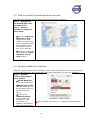
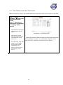
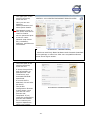
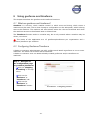
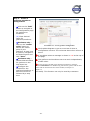
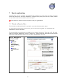
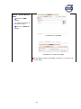
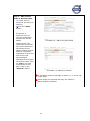
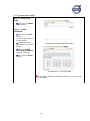
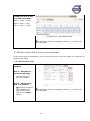
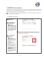
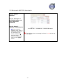
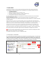
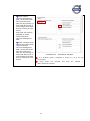
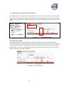
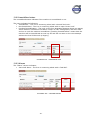
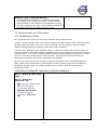
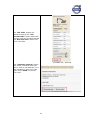
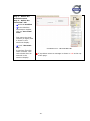
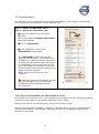
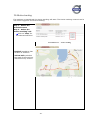
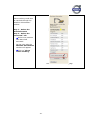
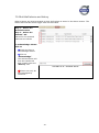
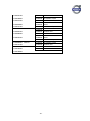
User manual for Dealers CareTrack Volvo Construction Equipment Telematics System 2015-01-05 M1 2015 i ii Index 1 INTRODUCTION ................................................................................................. 1 1.1 1.2 1.3 1.4 1.5 1.6 1.7 2 ADMINISTRATIVE FUNCTIONS .................................................................... 3 2.1 2.2 2.3 2.4 2.5 2.6 2.7 2.8 2.9 2.10 2.11 3 WHO SHOULD READ THIS DOCUMENT? .............................................................. 1 WHAT IS TELEMATICS?...................................................................................... 1 PREREQUISITES .................................................................................................. 1 TECHNICAL REQUIREMENTS .............................................................................. 1 SYMBOLS USED ................................................................................................. 1 DISCLAIMER ...................................................................................................... 2 SUPPORT ............................................................................................................ 2 WHAT IS A USER?............................................................................................... 3 WHAT IS A MACHINE? ........................................................................................ 3 CREATE A NEW USER ......................................................................................... 3 DELETE A USER .................................................................................................. 4 CREATE A NEW CUSTOMER ................................................................................ 5 DELETE A CUSTOMER......................................................................................... 5 EDIT MY PROFILE ............................................................................................... 6 CREATE A NEW MACHINE .................................................................................. 6 DELETE A MACHINE ........................................................................................... 7 CREATE A SUB-DEALER ..................................................................................... 7 DELETE SUB-DEALERS ....................................................................................... 8 GENERAL USAGE TIPS .................................................................................... 9 3.1 SELECT MACHINES ............................................................................................. 9 3.1.1 3.1.2 3.1.3 3.2 4 HOW DO I CREATE CUSTOMER AND ACTIVATE MACHINES? ........ 13 4.1 4.2 5 Search for specific machines .......................................................................................... 10 Manage and create new filters........................................................................................ 11 Machine status ................................................................................................................ 12 CREATE AND ATTACH ...................................................................................... 12 STEP 1 - CREATE A NEW CUSTOMER ................................................................ 13 STEP 2 - CREATE A NEW MACHINE .................................................................. 14 MAPS, MACHINE POSITIONS AND MACHINE SUMMARY .................. 18 5.1 5.2 5.3 5.4 5.5 VIEW MACHINES ON MAP ................................................................................. 18 VIEW AND SELECT ALL MACHINES WITHIN MAP AREA...................................... 19 REQUEST UPDATE FROM MACHINE ................................................................... 19 VIEW STATUS REPORT AND FUEL LEVELS ........................................................ 20 VIEW MACHINE INFORMATION & MACHINE SUMMARY ................................... 21 5.5.1 5.5.2 6 Machine Information ...................................................................................................... 21 Machine Summary .......................................................................................................... 21 USING GEOFENCE AND TIMEFENCE ........................................................ 23 6.1 6.2 6.3 WHAT ARE GEOFENCE AND TIMEFENCE? ......................................................... 23 CONFIGURING GEOFENCE/TIMEFENCE ............................................................ 23 ATTACH GEOFENCE/TIMEFENCE....................................................................... 25 3 7 SERVICE PLANNING ....................................................................................... 27 7.1 7.2 7.3 7.4 7.5 8 BRAKE TEST ..................................................................................................... 32 8.1 9 CREATE A SERVICE PLAN ................................................................................ 27 ATTACH SERVICE PLAN TO ONE OR SEVERAL MACHINES .................................. 30 ACKNOWLEDGE SERVICE PLAN ........................................................................ 30 USING WEAR PARTS ......................................................................................... 31 ATTACH WEAR PART TO ONE OR SEVERAL MACHINES ...................................... 32 VIEW AND ACKNOWLEDGE BRAKE TEST RESULTS .......................................... 33 MANAGE ALARMS AND ERROR CODES .................................................. 34 9.1 9.2 9.3 9.4 FILTER ALARMS AND ERROR CODES BY PRIORITY ............................................ 34 VIEW AND ACKNOWLEDGE ALARMS AND ERROR CODES ................................ 34 MANAGE ALARM NOTIFICATIONS .................................................................... 35 ATTACH NOTIFICATION PLAN TO ONE OR SEVERAL MACHINES ........................ 37 10 MANAGE REPORTS ......................................................................................... 38 10.1 DAILY HOURS .................................................................................................. 38 10.2 MACHINE UTILIZATION .................................................................................... 39 10.3 MACHINE SPECIFIC PRODUCTIVITY REPORTS ................................................... 40 10.3.1 10.3.2 10.3.3 10.3.4 10.3.5 Wheel loader reports ...................................................................................................... 40 Crawled excavator reports ............................................................................................. 41 Wheeled excavator reports ............................................................................................. 42 Articulated hauler reports .............................................................................................. 43 Grader reports ................................................................................................................ 44 10.4 PRODUCTION ................................................................................................... 44 10.5 FLEET MANAGEMENT REPORTS ........................................................................ 45 10.5.1 Fleet reports Email Status .............................................................................................. 47 11 MANAGE WORK SHIFTS ............................................................................... 47 11.1 PROCESS OF CREATING WORK SHIFTS............................................................... 47 11.1.1 11.1.2 Work shifts overview ....................................................................................................... 47 Create work shifts ........................................................................................................... 48 11.2 ATTACH A WORK SHIFT TO ONE OR MORE MACHINES ....................................... 49 11.2.1 Attach work shift ............................................................................................................. 49 12 MATRIS DATA DOWNLOAD ......................................................................... 50 12.1 MATRIS DOWNLOADS .................................................................................... 50 12.2 AUTOMATIC MATRIS DOWNLOADS ............................................................... 51 13 ANTI-THEFT ...................................................................................................... 52 13.1 ACTIVATION OF ANTI-THEFT ........................................................................... 52 13.2 MACHINES ACTIVATED WITH ANTI-THEFT ....................................................... 54 13.2.1 13.2.2 13.2.3 13.2.4 Service action ................................................................................................................. 54 Immobilized status .......................................................................................................... 55 Alarms............................................................................................................................. 55 Triggers .......................................................................................................................... 56 13.3 AUTHORIZATION AND PIN-CODES ................................................................... 57 13.3.1 Authorization levels ........................................................................................................ 57 13.3.2 Find or change Pin code level 1 (only for customers) .................................................... 57 13.3.3 Change Pin Code level 2 ................................................................................................ 59 4 13.3.4 One Time Pin Code (only for customers in certain markets).......................................... 59 13.4 IMMOBILIZATION ............................................................................................. 61 13.4.1 13.5 13.6 How to de-immobilize an immobilized machine ............................................................. 61 ACTIVE TRACKING ........................................................................................... 62 ANTI-THEFT ALARMS AND HISTORY ................................................................. 64 14 APPENDIX, CODES, ABBREVIATIONS AND ROADMAP ....................... 65 14.1 THE W-ECU HARDWARE ROADMAP ............................................................... 65 5 1 Introduction Welcome as a user of the Volvo CE telematics system – CareTrack. This User Manual is intended as a Guide for users at Volvo CE Dealers, sub-dealers, Rental outlets and in some cases, large fleet-owners. 1.1 Who should read this document? This document is intended for both administrators and normal users using the portal in the CareTrack system. 1.2 What is Telematics? Telematics is the use of electronic and communication technologies to provide mobility services for the users. The service is intended to promote fuel efficiency, uptime, productivity and safety/security. It relies on a wireless communication link and often includes a positioning system. Examples of areas where Telematics is used are fleet management, rescue and breakdown calls. A Telematics system is built up by a unit in the machine containing a mobile phone, a GPS unit, a computer and sometimes a satellite modem. The unit is communicating over the mobile network through 3G, GPRS, SMS and other wireless communication bearers with applications and databases containing information. The information is displayed on a password protected website from which a user also can interact with a machine. 1.3 Prerequisites A valid user name and password is needed for secure access to the portal. A dealer administrator can create a new user in the system and the user can afterwards modify his password. A dealer creates accounts and connects machines to those accounts. The customer administrator can manage users in his/her portal. (See chapter 2) A customer can also be a sub-dealer or a rental outlet owned by the dealer. 1.4 Technical Requirements The following Web browser version is supported for the portal: Microsoft Internet Explorer version 10, 11 Operating system – Microsoft Windows XP or newer Other browsers might work perfectly well, but with small deviations in look and feel 1.5 Symbols Used Marks important information * This indicates that this information is mandatory. If the marked name fields are not filled in, the order will not be able to be fulfilled. -1- Indicates a mouse action Indicates that the action involves typing in entries Screenshots are inserted in order to give an illustrative example of each action. The purpose of the Screenshot is to demonstrate the correct screen the user should be working in. Details may not be fully visible. 1.6 Disclaimer Please note that the functions and the environment of the portal are continuously developed and therefore all material is subject to change without special notice. The latest version of the manual will always be linked to the CareTrack portal and is accessible by clicking the help icon. 1.7 Support If you have any questions regarding CareTrack, you should contact the support department for your region. Find the contact address on the VDN, under CareTrack. -2- 2 Administrative functions Administrative functions allow adding to the system machines and users of different kinds. 2.1 What is a user? Users have a username, password and a personal profile with user settings. There are two different types of dealer users in the CareTrack system: Dealer o administrator o user These user types have different rights in the system. A dealer administrator can perform certain tasks like creating users and machines whereas a dealer user only can perform basic operations like , for example, finding vehicle on the map. 2.2 What is a machine? Creating a machine in the system means entering configuration data for the hardware unit that is mounted on the machine and data for the actual machine (type, name etc. etc.). This information constitutes a machine in the system. 2.3 Create a new User This function can be performed by a dealer with administrative rights or a customer administrator. User within the dealer can be created and they can be assigned either administrative rights or be a normal user. Step 1 – Select administration menu Click on “Administration” in the top menu bar. Screenshot 2.1 - Administration view -3- Step 2 – Create the user by selecting users tab Select the tab “Users”. Click on the “Add” button to add a new user. () Enter the user details in the fields. Select the Administrator role if the user shall have administrative rights. Select Language, Units and time zone in the drop-down lists. Screenshot 2.2 - Create user Some steps are required and they are marked *. Other steps are optional. If a problem arises a message is shown in red at the top of the page. After entering all required fields click on “Save”. 2.4 Delete a user This function can be performed by a dealer with administrative rights. Step 1 – Delete a user Select the “Users” tab and click the delete button (waste bin icon) for the user to be removed. Click on the “OK” button on the pop-up dialog that follows. The user is deleted. Screenshot 2.3 - Delete user If a problem arises a message is shown in red at the top of the page. -4- 2.5 Create a new Customer A Dealer can create customers in the system. This must be done before attaching any machines to the customer. See chapter 4.1 Step1 Create a new Customer, for more details in this area. 2.6 Delete a customer This function can be performed by a dealer with administrative rights. Step 1 – Delete a Customer Select the Customer tab and click the delete button (waste bin icon) for the Customer to be removed. Click on the “OK” button on the pop-up dialog that follows. The customer is deleted. Screenshot 2.4 - Delete customer If a problem arises a message is shown in red at the top of the page. -5- 2.7 Edit my profile This function can be performed by all users. A user in the system can change his/her own information and password in the “My profile” part on the portal (in order for the changes to become active, the user needs to log-off and log-in once again). If more than 90 days has passed since the user last changed its password, the user will come to a new form page when the user log-in where the user is required to enter the old and the new password. If it is within 7 days before the forced password change the user will only get a warning pop up telling that its password is about to expire and that the user should change the password in “My Profile”. Step 1 – Select the administration menu Step 2 – Select the “My Profile” tab () Enter the user details in the fields After entering all required fields click on “Save”. Screenshot 2.5 - Edit profile If a problem arises a message is shown in red at the top of the page. Some steps are required and they are marked *. Other steps are optional. 2.8 Create a new Machine This function can only be performed by Dealer Administrator. See chapter 4.2 Step 2 - Create a new Machine, for more details in this area. -6- 2.9 Delete a machine This function can be performed by a dealer with administrative rights. Step 1 – Delete a Machine Select the “Machine” tab and click the delete button (waste bin icon) for the Machine to be removed. Click on the “OK” button on the pop-up dialog that follows. The Machine is deleted. Screenshot 2.6- Delete machine If a problem arises a message is shown in red at the top of the page. 2.10 Create a sub-dealer A dealer with administrative rights can create sub-dealers. Dealers can have sub-dealers and sub-dealers can have their own sub-dealers and so on. Step 1 – Select the administration menu Step 2 – Select the “Dealer” tab Click on the “Add” button to add a new Dealer. () Enter the user details in the fields. Select Language, Units and timezone in the drop-down lists. After entering all wanted parts click on “Save”. Screenshot 2.7 - Create sub-dealer If a problem arises a message is shown in red at the top of the page. Some steps are required and they are marked *. Other steps are optional. When a sub-dealer creates a machine, it will be visible to the HQ dealer account. If a sub dealer attaches the machine to a customer, the HQ dealer will be unable to assign the machine to another sub-dealer account. The sub-dealer must assign the machine back to their sub-dealer as the owner in order to do this. -7- 2.11 Delete sub-dealers This function can be performed by a dealer with administrative rights. Step 1 – Delete a Dealer Select the “Dealer” tab and click the delete button (waste bin icon) for the Dealer to be removed. Click on the “OK” button on the pop-up dialog that follows. The Dealer is deleted. Screenshot 2.8- Delete sub-dealer If a problem arises a message is shown in red at the top of the page. -8- 3 General usage tips There are some usage patterns that are generally applicable all over the portal; they are listed in this chapter. 3.1 Select machines Using the CareTrack portal is about working with a machine or set of machines to perform certain operations and tasks. To do this, select a machine by left-clicking on a machine in the machine tree on the left side. Once a machine is selected, one can right-click on it to: view the machine on the map; view the machine summary; or request a machine update. Select multiple machines by holding down the “control” key and left-clicking on additional machines. Select a consecutive range of machines by left-clicking on the first machine, then holding down the “shift” key and left-clicking on the last machine. One can view multiple machines on a map, and perform operations like compiling reports for selected machines. Screenshot 3.1 - Select machines In some cases machines can be selected in other manners. The machines can be filtered in different types: Custom groups - These groups are created and managed in the Administration menu, under the “Custom groups” tab. Machine type – Machines are grouped by wheel loaders, excavators, etc. Machine status – Machines are grouped according to their color-coded status. -9- To configure the Machine tree click on the “Open Configuration” icon. Here you can choose to display the machines by Machine name or Chassis id. Screenshot 3.2– Filter The choice of showing the full machine name is also available here. To save the new configurations check the “Save tree state” box. Screenshot 3.3– Configuration of Filter 3.1.1 Search for specific machines To search for specific machines through machine name or Chassis ID is possible in the search field in the machine tree. () Type the machine name (or Chassis ID) in the search field in the machine tree. Screenshot 3.4– Filter - 10 - Screenshot 3.5– Configuration of Filter Note, if you want to search and display the Chassis ID, remember to change the configuration to display Chassis ID instead of machine name. 3.1.2 Manage and create new filters Custom made filters can also be created and saved. Step 1 – Click on “No Filter” in the Machine tree window Step 2 – Select the “Manage filter” Click on the “New Filter” button to add a new filter. Or Click on an existing filter to edit. Select the conditions you would like to filter on. ()/ Add or select more conditions. Click “Save”. Screenshot 3.6– Manage Filter In this example, machines with A25F or A30F in the machine name within the Building segment will be viewed when using the filter. To take a filter away, select “No filter” in the Machine tree. Screenshot 3.7– Create Filters - 11 - 3.1.3 Machine status In the machine tree, the machines’ status when the machines last communicated is shown by a colored line. The color indicate the following status: Red: Green: Yellow: Grey: Position/Status reported within 96 hours with engine off (Key-on) Position/Status reported within 96 hours with engine on Position/status older than 96 hours Machine has never initialized or reported, or software does not support the status* The color status icons can also be seen in the Status Report (Top Menu: Mapping & Tracking Tab Status report). Screenshot 3.8 – Color status icon * If the machine (W-ECU) has any of the main software (MSW) numbers listed below the machine status will show a grey line. 11443690P01 11443779P01 11443839P01 11443888P01 11443967P01 11380034P01 11380036P01 3.2 Create and attach Most times when something in CareTrack is created, the usage pattern is the same. Step 1 is to create a general configuration, name it and save it. There is now a configuration ready to be used. Step 2 is to attach a configuration to one or several machines. This pattern applies to: Service Plans Wear parts Geofences Timefences Shifts Notification Plans - 12 - 4 How do I create customer and activate machines? This chapter describes the process for a dealer to activate a customer in the CareTrack system and how to assign machines. See chapter 2. Administrative functions for more detail regarding administration. 4.1 Step 1 - Create a new Customer This function can only be performed by a dealer with administrative rights. Step 1 – Select the administration menu Step 2 – Select the “Customer” tab Click on the “Add” button to add a new customer. () Enter the Customer details in the fields*. Select Country, Language, Units and time zone in the drop-down lists. After entering all required fields click on “Save”. Screenshot 4.1 - Create customer If a problem arises a message is shown in red at the top of the page. Some steps are required and they are marked *. Other steps are optional. Correct format for entering mobile phone number is: country code followed by phone number. Ex: +4616123456 * If the customer is part of a Key Account group, your Regional Volvo CE CareTrack administrator can arrange for the customer to be linked in the Key Account function. All machines that are then attached to this customer will be visible to the Key Account administrator, on their CareTrack screen. For more information on the Key account function – contact your Volvo CE Customer CareTrack administrator. * The customer ID field must be at least five characters and no more than seven characters. The characters can be either upper or lower case letters or numbers. No special characters are allowed(-,+,@,&,$,..etc). Also before creating a new customer account, be sure to verify that an account has not already been setup. If it has been agreed with the customer that they should be given access to Error Codes, then check the appropriate boxes before saving. The dealer should then ensure that the customer is trained in how the Error Code function in CareTrack is used, as this is NOT covered in the customer user manual. - 13 - 4.2 Step 2 - Create a new Machine A machine can only be created by a dealer with administrative rights. By using the Machine form on the administrator page, machines can be added, edited and removed from the system. Step 1 – Select the administration menu Step 2 – Select the “Machines” tab Click on the “Add” button. () Enter the machine details in the fields. Select in the dropdown lists. After entering all required fields click on “Save”. Screenshot 4.2 – Click Add to start registration of a new machine Screenshot 4.3– Register new machine - 14 - If a problem arises a message is shown in red at the top of the page. Some steps are required and they are marked *. Other steps are optional. Chassis ID: • () The first step is to enter the Chassis ID as follows (see notes on the right); Screenshot 4.4– Enter Chassis ID NOTES: This MUST be entered without blank spaces, where the machine type is up to 5 positions and the serial number is 6 positions. See examples below; L180E Serial No. 5932 enter as L180E005932 L180FHL Serial No. 15245 enter as L180F015245 L60F Serial No. 5707 enter as L60F005707 A25D Serial No. 15001 enter as A25D015001 EW180B Serial No. 759999 enter as EW180759999 EW180E Serial No. 354245 enter as G990 Serial No. 39300 enter as G990039300 EC35C enter as C35C110011 Serial No. 110011 W180E354245 EC45pro Serial No. 235689 enter as C45235689 ECR58 enter as C58110011 Serial No. 110011 ECR145C Serial No. 235689 enter as CR145235689 EC210C Serial No. 180001 enter as EC210180001 EC210EL Serial No. 180001 enter as C210E180001 FC3329C Serial No. 110011 enter as F3329110011 PL7015C Serial No. 110021 enter as P7015110021 G946B Serial No. 575001 enter as G946B575001 DD70 enter as D70110011 Serial No. 110011 BL70 Serial No. 575001 MC80B Serial No. 110011 MC110B MC330 Serial No. 110021 Serial No. 235689 enter as B70575001 enter as M80B110011 enter as M110B110021 enter as H330235689 MT2000 Serial No. 110011 enter as F200110011 MW500 Serial No. 575001 enter as V500575001 PT125 Serial No. 235689 enter as T125235689 PF6110 Serial No. 110011 enter as P611110011 RW195 Serial No. 180001 enter as R195180001 SD100 Serial No. 110011 enter as S100110011 - 15 - For Older Volvo, Non-Volvo and service vehicles, the “Chassis ID” created using VcadsPro during the kit installation should be entered E.G. CT1000025. • Click outside of the Chassis ID box. Screenshot 4.5– Chassis ID box If the chassis ID has been entered correctly, the correct Brand, Product Line & Model will appear in grey Chassis ID: • • • If trying to register a machine not compatible with the hardware or the Chassis ID is entered incorrectly, the message shown will appear. Screenshot 4.6– Wrong entry If the Chassis ID is entered correctly but this message appears, the machine has not communicated with the CareTrack portal. Start the machine again to enable the communication. If there is no communication at all, try to Reset the MID 142 W-ECU (not by ticking the box but by Physically when connected with techtool or check with your region) Screenshot 4.7– Error message Screenshot 4.8– Machine hours should be set to 0 On embedded software machines (GPPE) using “Advanced“ CareTrack machine hours offset should be set to 0. CareTrack detects the figure automatically. On Compact, Old Volvo & Non-Volvo machines using “Basic” CareTrack, the engine hours must be filled in and the “Reset machine hours” box checked. - 16 - Remaining fields: • () Name the machine and fill in the other fields as required. • () For a machine to be visible to a Key Account, the customer chosen under *Owner must be linked to that Key Account. • Select the desired service packages. Click on the arrow in order to have the packages selected. • Press “Save”. • The machine will be added to the Custom Group Unassigned, or the group selected during registration. Screenshot 4.9- Create machine more info If a problem arises a message is shown in red at the top of the page. Some steps are required and they are marked *. Other steps are optional. - 17 - 5 Maps, Machine positions and Machine Summary One of the key functions in the CareTrack portal is the ability to retrieve positions from machines and to display them on a map. 5.1 View machines on map The last stored position is used when displaying a machine’s position. Step 1 – View Machines on map Select Machines in the left-hand menu. Right-click on the selected machines in the left-hand menu. A menu turns up, click on View on Map. Screenshot 5.1 - View machines on map Note, Machines appearing in the middle of the ocean are machines that either need a reset and proper configuration or updated W-ECU software. - 18 - 5.2 View and select all machines within map area The last stored position is used when displaying a machine’s position. Step 1 – Navigate to the desired map view and zoom level Step 2 – View all machines in map and select them Click the “Show all machines in map” button in the map toolbar just above the map. All machines that have positions within the map area shall turn up on the map. Screenshot 5.2 - View and select all machines on map Select the machines by clicking the “Select machines in map view” button. 5.3 Request update from machine ”Request Update” means that a message is sent to the machine asking for current position, current machine hours, and current fuel level (also referred as “Pinging” the machine). Step 1 – Request position and machine hours update Select Machines in the left-hand menu. Right-click on the selected machine(s) in the left-hand menu to see the machines menu. Click on the “Request update” link to get a fresh position from the machine(s). In addition, the machine hours will be updated. Screenshot 5.3 - Request update Note, Machine needs “Key on” to get an accurate update - 19 - 5.4 View Status report and Fuel levels Machine locations, status, last update date & time and fuel levels can be viewed in list form. Step 1 – Select machines, Right Click and select Request update Step 2 – Navigate to Status Report (Mapping & Tracking: Status Report) The selected machines will be shown in list form. Moving the mouse over the fuel level bar will show the actual level in %. A level under 15% will show as red. Under 5% the bar will be completely red. Click on the arrow to see details of fuel level*. Screenshot 5.4 - View Status report * Machines with Early Basic hardware and Caretrack Standard service package but older non-compatible software cannot show fuel level. (Software in Engine or other ECU’s) - 20 - 5.5 View Machine information & Machine summary 5.5.1 Machine Information Step 1 – Click on a machine row in Status report, Operation reports or under Service plans The machine information panel will appear on the righthand side. Here you can see the latest update time, position, engine hours and engine status*. Screenshot 5.5 – Machine Information * Machines with Early Basic hardware and Caretrack Standard service package but older non-compatible software cannot show engine status. (Software in Engine or other ECU’s) 5.5.2 Machine Summary To select the Machine Summary, either right-click in the machine list and select ‘Summary’. Or click on the “Machine Summary” button in the Machine Information panel. Screenshot 5.6 – Select Machine Summary - 21 - The upper part of the machine summary looks like this Here you can see Machine, Dealer/Customer and subscription details. The Network map* is also shown and can be useful to Dealer service personnel prior to service visits. Network map shows ECU, Hardware, Software, and data set information. Screenshot 5.7 – Machine Summary * Machines with Early Basic hardware and Caretrack Standard service package or other but older non-compatible software cannot show engine status. The lower part of the machine summary looks like this. It shows last position, and information on attached Geo- and Timefences, and Automatic MATRIS downloads. If a work shift is attached, this will also be shown. The W-ECU Configuration Process is also shown. Here you can see if the process was completed. If not, reset the configuration process with VCADS Pro or contact your support department within your region. Screenshot 5.8– Machine Summary - 22 - 6 Using geofence and timefence This chapter describes the geofence and timefence functions. 6.1 What are geofence and timefence? Geofence is a service, which enables control in which area and during which times a machine may be used. This is done through a configuration on the web portal, which is being sent to the machine. The machine will send alarms when the rules are breeched and when the machine returns to the allowed area or allowed time. The Timefence function works in a similar way, but it only controls when a machine may be driven, not where. The limits of the application are 15 geofences/timefences per organization and 1 geofence/timefence per machine. 6.2 Configuring Geofence/Timefence A dealer or customer administrator can add, configure and attach a geofence to one or more machines. The same can be done with a timefence. A dealer or customer user can attach already created geofences and/or timefences to machines. Step 1 – Navigate to the configuration page for geofence/timefence Click on “Mapping & tracking” in the top menu. Click on the “Geofence” or ”Timefence” tab. Click on the “Geofence” or ”Timefence” button. Screenshot 6.1 - Configuring Geofence - 23 - Step 2 – Create a geofence/timefence configuration Click on the ”Add” button to navigate to the configuration page for geofence or timefence. () Enter desired name for geofence/timefence. Geofence only – Click on the “center point” button to choose the center point of your geofence. A map view is opened, navigate to the desired point and click “Save”. Screenshot 6.2 – Create geofence configuration Click update diagram to get an overview of when a configuration is active. The red areas show when a fence is active. If a problem arises a message is shown in red at the top of the page. Geofence only – Choose desired radius for geofence in the drop down list. The geofence and timefence services work independently of each other. Configure the schedule for the geofence/timefence. A start time must be followed by a stop time. check the Immobilizer box. Before using this function, please read the Antiplease read the Anti-theft section of the manual (see chapter 13. chapter 13. Anti-theft). This function can only be used by customers. To activate the Anti-theft trigger Geofence/Timefence, check the - 24 - Example on how to configure the schedule of a geofence/ timefence Geofence/timefence activated Monday to Friday between 5 pm and 7 am and during weekend. Green dot: start activation Red dot: end activation Red areas in graph: timefence/geofence activated Screenshot 6.3– Example of geofence/timefence If a problem arises a message is shown in red at the top of the page. 6.3 Attach geofence/timefence A geofence or timefence must be activated for a selection of machines to work. The way of doing this is the same for both geofence and timefence. Step 1 – Navigate to the geofence/timefence page Click on “Mapping & tracking” in the top menu. Click on the “Geofence” or ”Timefence” tab. Click on either “Attach: geofence” or “Attach: timefence”. Screenshot 6.4 – Navigate - 25 - Steg 2 – Activate geofence/timefence configuration Choose geofence/timefence in the drop down lists for each machine and click corresponding “Apply” button. or Choose geofence/timefence in ”Attach to all in list” and click on the “Apply” button to attach a selected fence to all selected machines. Screenshot 6.5 - Activate geofence If a problem arises a message is shown in red at the top of the page. The geofence and timefence services work independently of each other. Machines must be selected. - 26 - 7 Service planning Service plans can be created and attached to machines to keep track of when services should be carried out. It is also possible to configure wear parts, such as tires, teeth, brakes or any other items not covered by a service plan. The maximum amount of service plans is 50 per organization. 7.1 Create a Service Plan This function can be performed by a dealer user with administrative rights. To keep track of next service occurrence, one or more service plans can be defined and attached to a set of machines. Three standard service plans are available in the system from start. These are 125, 250 and 500 hour intervals predefined, up to 10 000 hours. These cannot be edited but can be copied and Saved under another name. They can then be edited by the user. Step 1 – Navigate to the Service Plan overview Click on “Service Management” option in the top menu. Click on “Service Plan” tab. Screenshot 7.1 - Navigate Screenshot 7.2 - Navigate - 27 - Step 2 – Create Service Plans Click the “Add” button. () Enter the name of the service plan. Click the “Save as” button. Screenshot 7.3 - Click Add Screenshot 7.4 - Create service plan If a problem arises a message is shown in red at the top of the page. - 28 - Step 3 – Add service items to Service Plans () Enter service occasions (as many as desired). Click the “Save” button. If required, a maximum service interval measured in months can also be added. Checking the “Use relative service times” box means that there will always be the chosen interval period between reminders, regardless of when the last service was acknowledged. Standard service plans can also be used. Click on “Copy” icon and rename the service plan. Click on the “Save As” button. Screenshot 7.5 – Add service plan occasion Screenshot 7.6 - Add service occasion If a problem arises a message is shown in red at the top of the page. Some steps are required and they are marked *. Other steps are optional. - 29 - 7.2 Attach service plan to one or several machines A service plan has to be attached to one or more machine(s) to be able to track the next service occasion and also to receive alarms when the service occasion is imminent. Step 1 – Select machines Step 2 – Navigate to the Service plan page See instructions for navigation in the chapter above. Step 3 – Attach service plans to machine Select either a service plan to be attached for all selected machines or select service plans for each machine. Click on the “Apply” button. Screenshot 7.7 - Attach service plan to machines 7.3 Acknowledge service plan When a service was successfully carried out by a service technician the user can A service plan has to be attached to one or more machine(s) to be able to track the next service occasion and also to receive alarms when the service occasion is imminent. Step 1 – Select machines Step 2 – Navigate to the Service plan page Click the “Overview” button. Click the “Confirm” button to confirm Screenshot 7.8 – Overview active service plan - 30 - Step 3 – Acknowledge the executes service Click the “Acknowledge” button. If required you can set a correct date and machine hour of when the service was executed Screenshot 7.9 – Acknowledge a service plan 7.4 Using wear parts Wear parts is a concept very similar to service plans. Wear parts can be defined arbitrarily with name, lifetime and alarm before expiring. Step 1 – Adding wear parts Click on “Wear parts” button. () Enter the desired name, lifetime and alarm before expiring. Click on the “Add” button to save. Screenshot 7.10 - Create wear parts If a problem arises a message is shown in red at the top of the page. Some steps are required and they are marked *. Other steps are optional. Wear parts are attached to machines in the same manner ___service plans. as, - 31 - 7.5 Attach wear part to one or several machines This function can be performed by a dealer with administrative rights. Step 1 – Select machines Step 2 – Navigate to the Service plan page See instructions for navigation in the chapter above. Step 3 – Attach wear parts to machine Screenshot 7.11 - Attach wear parts Select either a wear part to be attached for all selected machines or select wear parts for each machine. Click on the “Apply” button. 8 Brake Test Brake Test is a stationary test which is schedulable and safe check of the service brakes condition. The brake test is schedulable from the Contronics display in the machine; it can be set at certain hourly intervals or set to a specific time on a daily basis. A manual test can be done at any time from the Contronics display, regardless of the scheduled settings. The brake test results are available to view in the CareTrack portal for all users. This service is only available for selected series of Articulated Haulers. And is part of the Service Management Package. - 32 - 8.1 View and Acknowledge Brake Test results To acknowledge the Brake Test results. Step 1 – Select machines Step 2 – Navigate to the Brake Test page Click on the “Service Management” tab in the top menu. Click on the “Brake Test” tab. Step 3 – Select wanted Brake Test results Check the box of selected brake test results. Click on the “Acknowledge” button. Acknowledged results are found in the “History” tab. Screenshot 8.1 – Navigate to Brake Test For F-Series Articulated Haulers produced before the introduction of the break test (Oct 2012), the software needs to be updated with VCADS Pro in order to receive brake test results. The 20 latest brake tests are saved in the machine and sent in with the other report data, once a day. Tests are saved for 400 days, and then moved to the offline database. - 33 - 9 Manage Alarms and Error codes The CareTrack system provides several types of alarms and error codes, for example, when a service is approaching or is overdue. The alarms can be forwarded for easy monitoring. 9.1 Filter alarms and error codes by priority Alarms and error codes are prioritized as Level 1, 2 or 3 based on level of importance. The filter function enables the user to filter by priority in the portal but it is also possible to show all alarms and error codes. Below the machine tree, the number of Level 1 alarms and error codes is shown and is also a link to the alarms and error codes page. Note that the priority 1 alarms and error codes shown below the machine tree are calculated based on the unacknowledged alarms and error codes. 9.2 View and Acknowledge Alarms and Error codes User can view the alarms in the CareTrack portal and acknowledge selected alarms. Step 1 – Select machines Step 2 – Navigate to the Alarms/Error codes page Click on the “Service Management” tab in the top menu. Click on the “Alarms”/”Error codes” tab. The alarms/error codes will be shown in list form. Filter function enables the user to sort by priority. Step 3 – Select wanted Alarms Check the box of acknowledged alarms/error codes. Click on the “Acknowledge” button. Acknowledged alarms/error codes are found in the “History” tab. Screenshot 9.1 – View and Acknowledge Alarms and Error codes - 34 - 9.3 Manage alarm notifications “Notifications” is a way of forwarding selected alarm types. The user can create different plans and select which alarms they want forwarded from which machines. The alarms can be delivered as SMS or e-mail. They can also be forwarded to other recipients. The maximum amount of notification plans per organization is 10. The maximum amount of external recipients per notification plan is 10. Step 1 – Select notifications Select the “Service Management” overview page and then click on the “Notification” tab. Click on “Add” and the screen shown in screenshot 8.1 will appear. Screenshot 9.2 – Creating a Notification plan If a problem arises a message is shown in red at the top of the page. - 35 - Step 2 – Select which CareTrack Alarms, Machine Error codes and alarms you want in the plan Click on the required type; CareTrack or machine specific. Click on the alarm(s) or error codes you want in the plan, and then on the “Add to plan” arrow. To remove from the list, click the opposing arrow. Select the forwarding method by checking the SMS or e-mail box in the Forwarding list. Repeat this process until the plan is complete. Name the plan and click on “Save”. Recipients can also be added to the notification. The message is then sent to you and the selected recipient(s). Screenshot 9.3 – Adding alarms & error codes to the Notification plan If a problem arises a message is shown in red at the top of the page. To check or uncheck all boxes in the SMS or E-mail forwarding column, click on the column heading - 36 - 9.4 Attach Notification plan to one or several machines A Notification plan has to be attached to one or more machine(s) so that the alarms and error codes can be forwarded via SMS or e-mail. Step 1 – Select machines Step 2 – Navigate to the Notification page Step 3 – Attach Notification plan to machine Select either a Notification plan to be attached for all selected machines or select Notification plans for each machine. Click the “Apply” button. Screenshot 9.4 - Attach Notification plan to machines For each user, a machine can only be attached to one Notification plan, though the same machine can be included in different users Notification plans at the same Dealer. The Volvo Dealer can attach an extra Notification plan to follow up the machines with an active Customer Support Agreement. - 37 - 10 Manage reports The CareTrack system offers a number of reports to follow machine hours, fuel consumption, Machine Utilization. The data in the portal is available up to 400 days and can be viewed in intervals of 125 days. The reports have been divided into groups: Daily hours Utilization reports Productivity machine reports (Encompasses specific reports for wheel loaders, excavators, articulated haulers and graders) All generated data reports can be viewed in: A specific date range that doesn’t exceed 125 days Previous day Last full week Last Month To be able to show data from a certain period the vehicle should have had the possibility to communicate the data towards the Caretrack portal. If not there will be no data shown for that period in time. 10.1 Daily Hours The daily hours report is valid for all machine types. This report type gives an overview of when and for how long the machines have been used. Steg 1 – Choose daily hours report Choose the “Daily hours” tab on the “Operation Reports” overview page. The report contains a per day report on how much the machines have been in use and how much they have been parked. To see an event report of the selected day, click on the icon to the right of the “Engine Off”. * Screenshot 10.1 – Daily hours If a problem arises a message is shown in red at the top of the page. * “Event report for that day” is only available if you have subscribed to the Operation Report service package. - 38 - 10.2 Machine utilization Operation Reports service package is needed! The machine utilization report contains machine hours, fuel consumption, Total Fuel consumed, work, and idle for the selected machines during the selected period in time. Step 1 – Choose machine utilization report Choose the “Machine utilization” tab on the “Operation reports” overview page. The report contains following data for the selected machines: -Machine name -Chassis-ID -Fuel consumption* -Total fuel consumed** -Relative amount of work*** - Relative amount of machine idle (P)*** -Machine hours Screenshot 10.2 – Machine utilization If a problem arises a message is shown in red at the top of the page. * This column shows the average fuel consumption based on the selected period in time. ** This column shows the total fuel consumption during the selected period in time. ***These columns show the distribution of the operating time for the machine, during selected period in time. The operating time is defined as the time with engine on. Definition for ART: Work is time in gear and idle is time in neutral and parked. The ART presentation of the machines utilization can only be seen as a guideline value since a full calculation of the machines utilization is more advanced. "Neutral", for example, includes time for loading and dumping which should be seen as operating time. Definition for WLO: Idle is engine speed less than or equal to idling and machine speed less than 0,5 km/h (0,3 mph). Work is all other times. Definition for EXC and EWS: Work is machine in work with the operation of attachments and tracks. Idle is engine running but attachments and tracks are not operated. Definition for GRD: Work is time in gear and idle is time in neutral and parked. - 39 - 10.3 Machine specific productivity reports Operation Reports service package is needed! The productivity report types are specific for each machine type (wheel loaders, excavators, articulated haulers and graders). These reports provide you a view on how the machines have been used. 10.3.1 Wheel loader reports Step 1 – Choose Wheel loaders report Choose the tab “Machine reports” on the “Operation reports” page and then the Wheel loader (icon). The report contains the following data for the selected machines: -Machine name -Chassis-ID Screenshot 10.3 – Wheel loaders -Machine hours -Average speed* -Total distance** If a problem arises a message is shown in red at the top of the page. -Amount of starts*** -High RPM**** -No. of high speed F-R, R-F shifts***** * This column shows the machines' average speed during the selected period in time. ** This column shows the machines' total distance travelled during selected period in time. Total distance means forward and reverse distance together. *** This column shows the total number of engine starts during selected period in time. **** This column shows if the engine speed has exceeded the maximum design speed, during the selected period in time. Never exceed the maximum engine design speed. Exceeding the maximum design speed may cause severe damage to the engine. ***** This column shows the total number of directional gear shifts R-F and F-R above 13,5 km/h or 8,388 Mph during the selected period in time. Transmission wear depends on current speed when shifting direction. Less machine speed when shifting direction generally causes less wear on the transmission. - 40 - 10.3.2 Crawled excavator reports Step 1 – Choose Crawled excavators report Choose the tab “Machine reports” on the “Operation reports” page and then the Crawled excavator (icon). The report contains the following data for the selected machines: -Machine name Screenshot 10.4 – Crawled excavators -Chassis-ID -Machine hours -Fuel consumption distributed on work modes* If a problem arises a message is shown in red at the top of the page. -Distribution of engine work mode** -Usage of Hammer/Shear/X3*** -Travel distribution**** * These columns show the fuel consumption distribution rate on each work mode, during the selected period in time. ** These columns show the time distribution of the engine work mode in percent, during the selected period in time. *** This column describes hydraulic X3/hammer/shear operating hours, during the selected period in time. **** These columns show operating hour distribution (%) on each travel speed for total travel time, during the selected period in time. - 41 - 10.3.3 Wheeled excavator reports Step 1 – Choose Wheeled excavators report Choose the tab “Machine reports” on the “Operation reports” page and then the Wheeled excavator (icon. The report contains the following data for the selected machines: -Machine name Screenshot 10.5 – Wheeled excavators -Chassis-ID -Machine hours -Fuel consumption distributed on work modes* If a problem arises a message is shown in red at the top of the page. -Distribution of engine work mode** -Usage of Hammer/Shear/X3*** -Travel distribution**** * These columns show the fuel consumption in each control mode, during the selected period in time. ** These columns show the distribution time of the control mode in percent, during the selected period in time. *** This column describes hydraulic X3/hammer/shear operating hours, during the selected period in time. **** These columns show the operating hours in different travel modes, during the selected period in time. - 42 - 10.3.4 Articulated hauler reports Step 1 – Choose Articulated haulers report Choose the tab “Machine reports” on the “Operation reports” page and then the Articulated hauler (icon). The report contains the following data for the selected machines: -Machine name Screenshot 10.6 – Articulated haulers -Chassis-ID -Machine hours -Average speed If a problem arises a message is shown in red at the top of the page. -Distance -Retarder* -Service brake* -Diff lock** * These columns shows the brake usage distribution between activated retarder and activated service brake (exceeding 4 bar), during the selected period in time. ** This column shows the percentage of engaged longitudinal difflock in relation to machine in motion during the selected period in time. The longitudinal difflock should always be disengaged when not needed, to reduce wear. The normal use of the longitudinal difflock in relation to the time that the machine has been operated depends on the operating conditions. Generally, the more offroad applications the machine operates in, the higher the longitudinal difflock use shall be in relation to the time that the machine has been operated. Also, operating in uphill conditions on a slippery surface can require longitudinal difflock. - 43 - 10.3.5 Grader reports Step 1 – Choose Grader report Choose the tab “Machine reports” on the “Operation reports” overview page and then the Motor grader (icon). The report contains the following data for the selected machines: -Machine name -Chassis-ID Screenshot 10.7 - Graders -Machine hours -Average speed* -Distance travelled** If a problem arises a message is shown in red at the top of the page. -Number of starts*** -No. of high speed F-R, R-F shifts**** * This column shows the machines' average speed during the selected period in time. ** This column shows the machines' total distance travelled during the selected period in time. Total distance means forward and reverse distance together. *** This column shows the total number of engine starts during the selected period in time. **** This column shows the total number of directional gear shifts R-F and F-R above 13,5 km/h or 8,388 Mph during the selected period in time. Transmission wear depends on current speed when shifting direction. Less machine speed when shifting direction generally cause less wear on the transmission. 10.4 Production Production service package is needed! On Board Weighing is a Volvo Construction Equipment production system that allows the user to weigh the load on the machine to increase the efficiency and to minimize overload. With On Board Weighing, the user can view the loading information in the CareTrack portal, inside the cab and load indication lights on the machine (only selected product platforms). To use On Board Weighing, the service needs to be activated in the CareTrack portal. You need to be logged in as a dealer admin and the machine must be On Board Weighing capable (correct hardware and software) for the option to be visible. On Board Weighing must be enabled by an authorized dealer service person using VCADS Pro. - 44 - Note! This needs to be activated by an authorized dealer and is part of the “Production” service package. Once this option is added it can generate an invoice or additional costs. This can also be switched off again. Step 1 – Navigate to the Production overview Choose the “Production” tab on the “Operation reports” overview page. The report contains the following data for the selected machines: - Machine name Screenshot 10.8 - Production - Chassis-ID - Machine hours - Total used fuel If a problem arises a message is shown in red at the top of the page. - Ton/hour - Ton/Fuel used - Fuel/Ton moved - Number of cycles - Cycle overload - Load util./cycle 10.5 Fleet management reports The fleet management report is designed for CareTrack users who manage a large population of machines and are interested in processing and analyzing large volumes of data in an efficient fashion. The fleet management report enables the user to generate several new and useful reports for selected machines during a defined period in time. While the reports are being generated the user can continue to work in the CareTrack portal. Once the reports are finished they are sent as attachments in an email to the logged-in user, each report in a separate excel file. The fleet management report is only available to Dealers, both users and admin. Customers do not have access to this feature. Report Types included: Status Report, Daily Hours, Machine Utilization and Machine Report (ART, GRD, WLO, Excavators and Wheeled), Alarms, Error Codes, Alarm Histroy and Error Code History. - 45 - Step 1 – Log-in as dealer user. Step 2 – Navigate to Operation Reports Choose the “Fleet” tab on the “Operations reports” overview page. Screenshot 10.9 – Navigate to Fleet Management Reports If a problem arises a message is shown in red at the top of the page. Step 3 – Select a date interval Step 4 – Select some report types Tick the boxes of the desired reports. Click on the ”Create Reports” button. Click on the ”OK” button to return to Fleet Summary main page. Screenshot 10.10 – Select Fleet Management Reports Screenshot 10.11 – Fleet Management Reports - 46 - 10.5.1 Fleet reports Email Status Step 1 – Navigate to Operation Reports Choose the “Fleet” tab on the “Operations reports” overview page. Step 2 – Click on “Fleet Email Status” Screenshot 10.12 – Navigate to Fleet Email Status If a problem arises a message is shown in red at the top of the page. 11 Manage Work shifts Operation Reports service package is needed! Work shifts can be used to generate reports and follow up specific drivers on different shifts. A maximum of three shifts can be defined for a machine per day. 11.1 Process of creating work shifts 11.1.1 Work shifts overview Step 1 – Navigate to the work shifts overview Choose the “Work shift” tab on the “Operations reports” overview page. Screenshot 11.1 – Work shifts If a problem arises a message is shown in red at the top of the page. - 47 - 11.1.2 Create work shifts Step 1 – View work shifts Click on the “Work shift” button. Step 2 – Create workshifts Click on the “Add” button. () Enter the name of the work shift. Choose the time periods for the specific shifts. Click on “Verify work shift schedule” to see a summary. Click on the “Save” button. Screenshot 11.2 – Choose list of work shifts Screenshot 11.3 – Create work shift If a problem arises a message is shown in red at the top of the page. - 48 - Example on how to set up a 24h work shifts Shift 1: 10 pm – 6 am Shift 2: 6 am – 2 pm Shift 3: 2 pm – 10 pm Screenshot 11.4 – Work shifts 24 hours If a problem arises a message is shown in red at the top of the page. 11.2 Attach a work shift to one or more machines A work shift must be attached to one or more machines to see the usage of a machine for specific work shifts. 11.2.1 Attach work shift Step 1 – Choose machines Step 2 – Navigate to the work shift page See instructions in previous chapter. Step 3 – Attach work shift to a machine Choose a workshift to be attached for each machine and click on the “Apply” button. Screenshot 11.5 – Attach work shift to machines If a problem arises a message is shown in red at the top of the page. - 49 - 12 MATRIS data download MATRIS data can be downloaded from machines with the advanced hardware. These files can later be used in Volvo’s MATRIS tool. A User can also choose to plan downloads every month, quarter, 250, 500 or 1000 engine hours. Note! MATRIS downloads can be made available to customers if desired (see chapter 4.1 Step 1 - Create a new Customer). 12.1 MATRIS downloads Step 1 – Choose machines Step 2 – Navigate to the MATRIS page Choose the “MATRIS” tab on the “Service management” overview page. If data has been downloaded, this is the place where the MATRIS data files can be found. Screenshot 12.1 – Overview, MATRIS files To have successful Matris downloads the machine must have “ignition key on” and a good GSM coverage for the download to be successful. Step 3 – Download MATRIS data Click on the “Download” button. Download options are shown for the chosen machines. 1. Complete: Download includes all items. 2. Partial: User can choose what do download. Min. 1 item. Max 5 items. Screenshot 12.2 – Download MATRIS data Important: If using satellite data transfer, it may take some time to retrieve and compile all data to a usable file! - 50 - 12.2 Automatic MATRIS downloads Step 1 – Select machines Step 2 – Navigate to the MATRIS page and select Automatic download Step 3 – Attach Intervals to machine(s) Select monthly, quarterly, 250, 500 or 1000 hour interval to be attached for all chosen machines or select for each machine individually. Click on the “Apply” button. Screenshot 12.3 – MATRIS files – Automatic download If a problem arises a message is shown in red at the top of the page. - 51 - 13 Anti-theft CareTrack Anti-theft is a Volvo Construction Equipment Anti-theft solution that allows immobilization of Volvo CE machines as a consequence of a violated condition such as… A trespassed geofence, A broken timefence, Machine movement when the ignition is off. No GSM or Satellite connection. (certain markets only) Or by tampering with the electronic systems. It is also possible for customers to immobilize the machine manually from the CareTrack portal (certain market only). This will immobilize the machine only at next start up when it has violated one of its conditions. It will never turn a machine off during the actual operation of a machine because of safety reasons. With Anti-theft, the user can view and manage various anti-theft alarms associated with machines. This includes the ability to safely enable and disable the use of the machine. Antitheft will only work in countries where CareTrack is launched and in selected markets. Using this service requires not only the responsible understanding and knowledge of the functions, but also the consequences regarding insufficient or incorrect usage of settings. Some of the sections in Anti theft cannot be accessed by the dealer. They are however still part of this manual as the dealer might need the information to support the customer. Note! This needs to be activated by an authorized Volvo Construction Equipment dealer and is part of the “Anti Theft” service package. This option can generate an invoice or additional costs. 13.1 Activation of Anti-theft To use Anti-theft, the machine needs to be activated in the CareTrack portal. You need to be logged in as a dealer admin and the machine must be Anti-theft capable for the option to be visible (Anti-theft must be enabled by an authorized dealer service person using VCADS Pro to make the tick box selectable). Anti-Theft is a subscription service and selecting this option could generate a monthly invoice to the dealer, until it is deactivated by the dealer. Step 1 – Select the administration menu Step 2 – Select the “Machines” tab Select a machine in the list and click on the Refresh button to add the machine. Click on the Select button to continue. Screenshot 13.1 – Activation of Anti-theft - 52 - Under Dealer ‘Service Packages to Add’, select Anti-theft from the Left hand side box by clicking on Anti-theft and move it to the Right hand side box by clicking on the arrow. Anti-theft will now be possible to select under Customer ‘Service Packages to Add’. If the customer also should have Anti-theft, under Customer ‘Service Packages to Add’, select Anti-theft from the Left hand side box by clicking on Anti-theft and move it to the Right hand side box by clicking on the arrow. Screenshot 13.2 – Activation of Anti-theft If a problem arises a message is shown in red at the top of the page. Some steps are required and they are marked *. Other steps are optional. - 53 - 13.2 Machines activated with Anti-theft In the Overview Tab of Anti-theft, the trigger status of the selected machines can be viewed. Search for all the machines with the ‘ON’ status, using the filter search. This feature shows the machines that have the Anti-theft switched ‘ON’. Other possible selections are ‘ALL’ and ‘OFF’. Step 1 – Select the Anti-theft menu Step 2 – Select the “Overview” tab Select ON, OFF or ALL in the filter search. Click on “Refresh”. Screenshot 13.3 – Find Anti-theft machines 13.2.1 Service action If the ”Service Action” indicates ‘ON’ it is part of a machine service procedure and will override triggers until the next start of the machine. Service action ‘ON’ can also be used for movement of machines (relocating the machine, as used by rental companies for example). Service action can only be enabled using Level 2 code in the machine or by an authorized dealer service person using VCADS Pro. Screenshot 13.4 – Service action - 54 - 13.2.2 Immobilized status The immobilized status indicates if the machine is immobilized or not. The icons indicate the following: Immobilized – The icon is a steering wheel with a closed ‘Red Lock’. Not Immobilized - The icon is a steering wheel with an open ‘Green Lock’. Pending Immobilization - The Lock on the Icon alternates between these two states, which means it oscillates from RIGHT ‘Green’ to LEFT ‘Orange/Red’ and then back and so on until the machine immobilizes (”Pending Immobilization” means that the machine will be immobilized at next key off and will not start on the next attempt without the level 2 PIN code (6 digits)). Screenshot 13.5 – Immobilized status 13.2.3 Alarms The ”Alarm” column indicates: Anti-theft Alarm - The Icon is a steering wheel with a ‘Red Bell’. Screenshot 13.6 – Anti-theft Alarms - 55 - 13.2.4 Triggers If you select an individual machine from the overview, a list of the immobilization ”triggers” and their status will be shown on the right hand side of the screen. When the anti-theft system is active and the machine is not immobilized, the trigger state is ‘OFF’. When a specific trigger has been activated and an alarm has been sent, the status changes to ‘ON’. The ”Update” button will refresh the current status. Step 1 – Select the Anti-theft menu Step 2 – Select the “Overview” tab Select one machine with Anti-theft activated. On the right side the Machine Information window will appear. Explanation of triggers: No connection (only in selected markets) - Machine can be immobilized automatically if no connection with portal has occurred within selected days. The default delay time is 60 days if activated. ECU Change - If any machine ECU is removed, system will detect and activate immobilization trigger functions. Mobile/GPS Antenna failure - Mobile and GPS antenna will be monitored by W-ECU and in any tampering action the violation trigger will activate machine immobilization. SIM Card - Mobile Tampering of the SIM card inside the W-ECU will be detected and activate immobilization trigger. Timefence - The authorized time window can be defined and if machine keeps working beyond defined limits, it will activate immobilization trigger. Machine movement - If any excessive movement is perceived by the machine when key off, it will activate the immobilization and also send current machine location in predefined intervals (active tracking). Remote immobilization - The machine can also be immobilized from the CareTrack portal (certain markets only). Telematic Power lost - Battery cable will be monitored by W-ECU and if power is interrupted a trigger will be activated. Open Box - Opening of the W-ECU unit will be detected and activate immobilization trigger. - 56 - Screenshot 13.7 – Triggers Geofence (only in selected markets) - A geographical area based on coordinate and radius can be defined as authorized to work. If the machine moves outside it will activate an immobilization trigger and active tracking will start. If the machine returns to specified perimeter the trigger return to ‘OFF’. 13.3 Authorization and PIN-codes 13.3.1 Authorization levels For CareTrack Anti-Theft there are three different authorization levels: A Level 1 is the operator level. He or she is using a four digit code to start a machine that is equipped with Anti-theft. There can only be one PIN code per machine and this code is always needed to start the machine when Anti-Theft is enabled. A level 2 user, that can be the machine owner, is using a six digit code. There is only one code per machine. This code makes it possible to log in to the machine instrument display to set new Level 1 code, reset a machine that has been locked because of wrong level 1 code input or to set Anti-theft system in service mode. This level has the authorization to immobilize a machine and also de-immobilize the machine. Level 3 is the level for service technician that are VCADS Pro users and authorized AntiTheft. When service technician is authorized he or she will get access to the VCADS Pro operations for Anti-Theft. For certain markets there is also a level 3 functionality in CareTrack portal. 13.3.2 Find or change Pin code level 1 (only for customers) Step 1 – Select the Anti-theft menu Step 2 – Select the “Overview” tab Select one machine with Anti-theft activated. On the right side the Machine Information window will appear. Click on “Pin Code”. - 57 - The ”Pin Code” button will display access to the ”Get current code” button where the current code can be retrieved and the ”Set new code” button will set a new code. Screenshot 13.8 – Pin Code The “Generate random” button will create a random code that can be sent to the Operator. It is also possible to enter your own code. Click “Send” to use the new code. Screenshot 13.9 – Find Pin Code - 58 - Screenshot 13.10 – Change Pin Code 13.3.3 Change Pin Code level 2 Change of the Level 2 Pin Code (owner pin code) can be done with VCADS Pro by an Antitheft authorized user. 13.3.4 One Time Pin Code (only for customers in certain markets) Machines working in a no GSM or Satellite signal condition and has the trigger “No connection” activated needs to use One Time Pin Code to not immobilize the machine after selected number of days. - 59 - Step 1 – Select the Anti-theft menu Step 2 – Select the “Overview” tab Select a machine In the Machine information window, click on “One-TimeCode”. First enter the Seed number (8 digits) that is shown in the machines display. Click “Generate Key”. A new One Time Pin Code is shown. This code should then be entered in the machine display. Screenshot 13.11 –One Time Pin Code If a problem arises a message is shown in red at the top of the page. - 60 - 13.4 Immobilization The machine can be immobilized by the triggers listed above. It can also be immobilized from the portal by the customer (certain markets only). Step 1 – Select the Anti-theft menu Step 2 – Select the “Overview” tab Select one machine with Anti-theft activated. On the right side the Machine Information window will appear. Click on “Immobilize”. To de-immobilize, Click on the “Immobilized” button again. The ”Immobilize” button will indicate ‘pending immobilization. The machine will immobilize only after an ignition ”switch off” at which point the button status will change to ‘immobilized’. On the next start up, this action will disable the machine and prevent it from further usage until the reason for the trigger has been resolved. NOTE: this can only be done by the customer. Using this feature should always be done in a well-managed way by knowing and understanding the consequences and circumstances. Screenshot 13.12 – Immobilization 13.4.1 How to de-immobilize an immobilized machine If the machine is locked for level 1 user (operators) the machine can be unlocked by waiting 5 minutes and try again or using owner PIN code (Level 2 code). Machines can also be de-immobilized by using a One Time Pin Code. Machines immobilized by geofence, timefence or antenna failure can be de-immobilized by reversing the violation. For example; repairing the antenna or changing timefence and geofence in the portal. - 61 - 13.5 Active tracking If a machine is immobilized the Active tracking will start. The Active tracking is saved until a new event triggers a new active tracking. Step 1 – Select the Anti-theft menu Step 2 – Select the “Active tracking” tab Click on “Map” for the selected machine. Screenshot 13.13 – Active tracking Red bell symbolize last location of machine Yellow bell symbolize the path of the machine, with bells every minute. Screenshot 13.14 – Active tracking map - 62 - Active tracking could also be reached through the “Machine Information” window. Step 1 – Select the Anti-theft menu Step 2 – Select the “Overview” tab Select one machine with Anti-theft activated. On the right side the Machine Information window will appear. Click on “Show active tracking”. Screenshot 13.15 – Active tracking map - 63 - 13.6 Anti-theft alarms and history When triggers are being activated an Anti-theft alarm is stored in the alarm section. The alarms will indicate which trigger that was activated. Step 1 – Select the Anti-theft menu Step 2 – Select the “Alarms” tab Alarms for the selected machines are shown To acknowledge alarms click on Check the box to acknowledge alarms. Click on “Acknowledge”. The selected alarm will then be transferred and viewed under the “History” tab. Screenshot 13.16 –Anti-theft Alarms Alarms can only be acknowledged by customer. - 64 - 14 Appendix, Codes, Abbreviations and Roadmap These examples are from the CareTrack User manual. Some of this codes and abbreviations are also included in the manual per section. Prefix Explanation GPRS General/GSM Packet Radio Service SMS Short messages service User types Explanation Dealer Administrator A type of user that have administrative rights within the dealer portal. A user like this can create customers, machines, sub-dealers etc. etc. This is a type of user that the dealer administrator creates. A user has access to the basic services within the portal A type of user that have administrative rights within the customer portal. This is a type of user that the customer administrator creates. A user has access to the basic services within the portal Dealer User Customer Administrator Customer User 14.1 The W-ECU Hardware Roadmap SW PN 11443688C08 11443839P01 11443888P01 11443967P01 11380034P01 11380036P01 11380134P01 11380207P01 11380216P01 11381234P01 11381456P01 11381647P01 11381864P01 11383157P01 W-ECU version WECU1 (old) HW PN 11443900 11443950 WECU1 11443975 WECU2 - 65 - Extra info 11383191P01 11383308P01 11383514P01 11384878P01 11385191P01 11384508P01 WECU2+ 11384642P01 11384680P01 11385053P01 11384856P01 WECU3 11385471P01 11384487P01 WECU3+ 11385009P01 11385468P01 11381207 Satellite com 11381209 No Satellite comm 11381460 Satellite com for Brasil NO Satellite com for 11381560 Brasil 11381465 For China only 11383209 No Satellite comm 11383207 Satellite com 11383460 Satellite com for Brasil NO Satellite com for 11383560 Brasil 11383465 For China only 11384310 No Satellite comm 11384320 Satellite com 11443993 No Satellite comm 11443992 Satellite com - 66 -