1
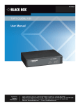
Model 7160 HD/SD/ASI/310 Protection DA
Model 7160
HD/SD/ASI/310
Protection DA
Data Pack
ENSEMBLE
D
E
S
I
G
www.ensembledesigns.com
N
Revision 1.0 SW v2.2.10
S
7160-1
Model 7160 HD/SD/ASI/310 Protection DA
Contents
MODULE OVERVIEW
4
SDI Signal Evaluation
4
DVB-ASI and SMPTE 310M Signal Evaluation
5
Block Diagram
6
APPLICATIONS
9
Auto-Switched Trouble Slide Application
9
Auto-Switched Upconversion Application
10
3RU and 1RU Backplane Diagrams
11
Status and Alarm Cabling
12
MODULE CONFIGURATION AND CONTROL
13
7160 Parameter Table
14
Front Panel Controls and Indicators
16
AVENUE PC REMOTE CONFIGURATION
17
7160 Avenue PC Menus
17
Status Menu
17
Config Menu
19
Black Detect Menu
20
Audio Detect Menu
21
Freeze Menu
22
ASI Config Menu
23
ASI Status Menu
24
Pri Errors Menu
25
GPI Menu
26
Inputs Menu
27
Memory Menu
28
www.ensembledesigns.com
7160-2
Model 7160 HD/SD/ASI/310 Protection DA
AVENUE TOUCH SCREEN REMOTE CONFIGURATION
29
7160 Avenue Touch Screen Menus
30
Status Menu
30
Config Menu
31
Black Detect Menu
32
Audio Detect Menu
33
Freeze Menu
34
ASI Config Menu
35
ASI Status Menu
36
Pri Errors Menu
37
GPI Menu
38
Inputs Menu
39
Memory Menu
40
TROUBLESHOOTING
41
SOFTWARE UPDATES
41
WARRANTY AND FACTORY SERVICE 42
Warranty
42
Factory Service
42
SPECIFICATIONS
www.ensembledesigns.com
43
7160-3
Model 7160 HD/SD/ASI/310 Protection DA
MODULE OVERVIEW
The 7160 Serial Digital Protection DA module is a fail-safe bypass protection switch for monitoring and
switching critical SD and HD paths in broadcast and satellite applications. When a fault is detected in
the Primary input, the switch will activate, causing the Secondary (backup) input to be switched to the
module’s distributed outputs. The switch can operate in two modes; automatic or nonresetting.
The 7160 monitors the integrity of the Primary serial digital input stream and analyzes the audio
and video content. Signal health and fault detection is determined by monitoring any or all of the
following parameters: Closed Caption Data, Timing Reference Signal (TRS), Black, Embedded Audio,
Error Detection and Handling (EDH), CRCs, and Freeze.
A sophisticated Black detection system is employed to activate the switch in the event signal is lost.
It allows the user to select not only the threshold and percentage of non-black pixels, but also the
portion of the picture to be considered.
The Freeze detection system can be set to detect a clean or noisy source. Freeze Time sets the number
of seconds that can elapse before the 7160 switches to the secondary input after a video freeze
condition is detected in the primary input.
SDI Signal Evaluation
The 7160 monitors the integrity of the serial digital input stream and analyzes its audio and video
content. Signal health and fault detection of SD SDI and HD SDI signals is determined by monitoring
any or all of the following parameters, in order of increasing complexity:
•
Timing Reference Signal (TRS) – This parameter checks for the persistent loss of digital sync
by looking for the correct Timing Reference Signal carried in the serial video stream. When this
digital sync format is correct, the signal is considered good.
•
Black – Black detection is based on three configurable parameters: black level threshold, black
pixel count, and black duration time. All of these parameters can be set using the menu system
to meet the needs of specific video signal inputs.
•
Embedded Audio – This parameter will look for correctly configured embedded audio
packets in the horizontal intervals of the signals. The actual audio content of the packets is
further analyzed to detect silence. Specific audio parameters, such as audio group, silence
threshold level, and audio silence duration can be configured in the Avenue PC and Touch
Screen menus.
•
Freeze – This parameter checks for a freeze condition as determined by the settings selected
in the Freeze menu.
A sophisticated black detection system is employed to activate the switch in the event signal is lost.
It allows the user to select not only the threshold and percentage of non-black pixels, but also the
portion of the picture to be considered. The area of the picture checked is determined by selecting
Small Window which is approximately two thirds of the picture width and height, or Big Window
which covers approximately 90% of the width and height. This allows a corner Bug to be either
excluded or included in the detection process.
www.ensembledesigns.com
7160-4
Model 7160 HD/SD/ASI/310 Protection DA
Black detection is performed on a pixel-by-pixel basis within the selected window, with user selectable
Detect Level and Blk Frac adjustments. Pixels above the Detect Level are considered as being nonblack. Blk Frac sets the percentage of pixels which must be non-black. If Detect Level is set to 12 IRE
and Blk Frac is set to 10% then the 7160 expects there to be pixel levels above 12 IRE for more than
10% of each frame. For example, if Blk Time is set to 3 seconds, if less than 10% of the pixels in each
frame are above the selected 12 IRE level for a period of 3 seconds, a switch will occur.
Pri Valid and Sec Valid are dynamic values based on incoming video. In the above example, if Pri
Valid fell below Blk Frac continuously for 3 seconds there would be a switch, provided that there
is valid secondary video. Note however, that the display may not keep pace with short duration
transitions of actual video. In the example, an excursion above 12 IRE for a single frame every 2
seconds would not cause a switch to take place, since the 3 second count would be reinitialized by
these valid frames.
DVB-ASI and SMPTE 310M Signal Evaluation
For DVB-ASI and SMPTE 310M signals, there are two levels of signal analysis available: Simple or
Advanced. Use the ASI Test control in the Config menu to choose between these.
When ASI Test is set to Simple, the 7160 looks for:
•
Input signal presence and digital clock lock
•
Presence of non-null (blank) packets
•
Presence of Program Allocation Table (PAT) PIDs occurring at least two per second
When ASI Test is set to Advanced, the 7160 looks for the above conditions, plus the following:
•
The presence of at least one program stream being called for in the PAT. The 7160 can
automatically look for the first one, or the user can tell it which of the first four it should look
for. This selection is made with the Pgm Target control in the ASI Config menu. The 7160
expects at least one Program Management Table (PMT) PID per second.
•
The targeted Program must contain at least one elementary Video Stream and one elementary
Audio Stream.
•
A user-defined minimum number of video packets each second in the Video PID.
•
A user-defined minimum number of audio packets each second in the Audio PID.
www.ensembledesigns.com
7160-5
Model 7160 HD/SD/ASI/310 Protection DA
The Pri ASI Status indicator show what has been detected in the incoming DVB-ASI or SMPTE 310M
stream.
Possible indications are:
•
Good – The DVB-ASI or SMPTE 310M signal passes all tests (either Simple or Advanced)
•
No ASI – No DVB-ASI or SMPTE 310M signal has been detected
•
No Packets - All of the packets in the stream are null. There are no actual program packets
•
No PAT - There are non-null packets, but no Program Allocation Table can be found
•
No PMT - No Program Management Table can be found
•
No Video - The user-defined minimum number of video packets per second has not been met
•
No Audio - The user-defined minimum number of audio packets per second has not been met
The ASI Status menu shows a breakdown of these elements of analysis with a display of live results.
The displayed values for the rate (in PIDs per second) for the video and audio can be used as a guide to
setting the Min Vid Rate and Min Aud Rate values for a particular system or installation.
Whenever the DVB-ASI test generates a result other than Good, a timer begins running. If that timer
reaches the ASI Time value set in the ASI Config menu, the channel will be marked as faulted and the
switch will move to the Secondary input.
When the program assignments in a DVB-ASI stream change, it can take up to a second for the 7160
detector to re-acquire all of the table information needed to show that the signal is good. For this
reason, a setting of between 2 - 5 seconds is recommended for the ASI Time parameter.
The Pri Errors menu shows error-seconds counters for all tests performed by the 7160. The ASI Vid
ErrSec control shows the cumulative number of seconds where the minimum packet rate was not
met. Depending on how the ASI Time control is set, these errors may or may not have actually caused
a program switch to occur. To reset the error-seconds counters, click them.
Block Diagram
The block diagram on the following page illustrates the signal flow of the 7160. Note that in the event
of power failure, the passive relay passes the primary input to the Relay Protected Output.
The Primary and Secondary inputs pass through serial digital receiver/equalizers for buffering. When
a fault is detected in the Primary input, and the Secondary input is seen as not faulted, the electronic
solid state switch will activate, switching the Secondary input to the output.
www.ensembledesigns.com
7160-6
Model 7160 HD/SD/ASI/310 Protection DA
Each of the signals is fed to identical detection circuits which evaluate multiple parameters and
characteristics of the signal in order to arrive at a fault decision. Detection of TRS errors is done in a
Receiver/Reclocker circuit which produces a reclocked serial output feeding a Deserializer circuit. The
output of this section then feeds a Field Programmable Gate Array (FPGA) where the signals are vetted,
or tested for configured parameters. The Signal Vetter™ process in the FPGA detects the parameters
chosen by the user using either the front panel controls or through the Avenue PC or Touch Screen
menus. Each of the chosen aspects are monitored independently, and when they fail to meet the
vetted standard, a fault condition is issued. Fault conditions can be monitored with an external alarm
system or other device through the 15-pin Control connector on the corresponding rear backplane
connector. The Form C relays status outputs from this connector can be monitored by a device to
show Primary and Secondary signal status and the current position of the protect switch (Primary or
Secondary).
Two GPI Override Inputs are available to allow changing switch position in response to triggers from
an external source. This can be used to manually reset the switch after the Primary has recovered from
a fault condition or set to respond to a signal state from an external device to trigger a switch.
The on-board CPU can monitor and report module ID information (slot location, software version
and board revision), and power status to the optional frame System Control module. This information
can be accessed by the user or set to register an alarm if desired using the remote control options
available.
Every function and parameter on the module can be controlled from an Avenue Touch Screen Control
Panel or the Avenue PC Control Application. Memory registers can be used to save the complete
configuration of the module, making it easy to change instantly between different configurations.
Modules at software version 2.2.0 or later support SNMP (Simple Network Management Protocol)
monitoring. For each applicable signal processing module, module, signal, and reference status are
reported. For complete details on using SNMP monitoring, refer to the Avenue System Overview in the
manual that accompanies each frame.
HD/SD
Primary Input
Primary
Loopback
Rcvr/EQ
Relay
Protected
Output
(Fail-safe)
Reclocker
Deserializer
& EDH Processor
Relay
Content
Analyzer
Primary Fail
Form C
Relay
Alarm Outputs
Protection
Watchdog
Protected
Outputs
(5 each)
Module Control System
Decision Arbitration
GPI Inputs
Secondary Fail
Sel Pri
Sel Sec
Switch Position
Common
GPI Override Inputs
Serial Port
Status Logging
Backplane
Interface
Avenue System Control
HD/SD
Secondary Input
Secondary
Loopback
Rcvr/EQ
Reclocker
7160 HD/SD/ASI/310 Protection DA, portrait layout
www.ensembledesigns.com
7160-7
Model 7160 HD/SD/ASI/310 Protection DA
HD/SD
Primary Input
Relay
Protected
Output
(Fail-safe)
Protected
Outputs
(5 each)
HD/SD
Secondary Input
Relay
Rcvr/EQ
Rcvr/EQ
Reclocker
Protection
Watchdog
Reclocker
Deserializer
& EDH Processor
Content
Analyzer
Module Control System
Decision Arbitration
7160 HD/SD/ASI/310 Protection DA, landscape layout
Form C
Relay
Alarm Outputs
Primary
Loopback
Primary Fail
Secondary Fail
Switch Position
Common
GPI Override Inputs
Status Logging
Sel Pri
Sel Sec
Serial Port
Avenue System Control
GPI Inputs
Backplane
Interface
Secondary
Loopback
7160-8
www.ensembledesigns.com
Model 7160 HD/SD/ASI/310 Protection DA
APPLICATIONS
Auto-Switched Trouble Slide Application
In the example below, the main program feed is input to the 7160’s primary input. The secondary
input is from a logo inserter and is a “Please stand by” graphic.
In the event that the provider’s program feed is not present, the 7160 automatically switches to the
secondary “Trouble slide” feed.
Feed from program
provider or network
SDI
Primary
7160
Protect Switch
Avenue
7420
“Trouble
Slide”
SDI
Program feed to air
SDI
Secondary
Auto-switching “trouble slide” feed with 7160 Module
www.ensembledesigns.com
7160-9
Model 7160 HD/SD/ASI/310 Protection DA
Auto-Switched Upconversion Application
The diagram below shows a typical use for the 7160 module, where it is used in conjunction with the
7900 Up/Down/Cross Converter module to form a fully-redundant, auto-switched conversion chain.
The Primary input is backed up with a Secondary input from a video server.
The 7160 Protection Switch can accept different types of signals on its two inputs. The 7160 autosenses and reports what type of signal it is receiving: HD SDI, SD SDI, ASI or SMPTE 310M.
Here, an HD SDI signal is fed to the Primary input while an SD SDI signal is fed to the Secondary input.
If the HD SDI signal is bad, and the 7160 switches to the SD SDI signal, SD SDI will be output.
The 7900 Up/Down/Cross Converter shown above accepts an SD SDI or HD SDI signal. The user
sets the 7900 to the desired output type. In this example, the 7900 is set to output HD 720p. If the
incoming signal is 720p, the signal simply passes to the output. If the incoming signal is 1080i, the
7900 cross-converts the signal and outputs 720p. If the incoming signal is SD SDI, the 7900 upconverts
the signal and outputs HD 720p.
Relay circuits accessible from the 15-pin D Control connector on the rear backplane can be connected
to alarms for monitoring Primary status and switch position.
Master
Control
HD SDI
Primary
7160
Protect Switch
Video
Server
(Backup)
SD SDI
HD SDI
or
SD SDI
7900
Up/Down/
Cross
Converter
HD SDI
or
SD SDI
Secondary
Control
Alarm Outputs
Redundant Auto-Switched Conversion with 7160 Module
www.ensembledesigns.com
7160-10
720p
To Transmitter
Model 7160 HD/SD/ASI/310 Protection DA
3RU and 1RU Backplane Diagrams
7160 PDA
Secondary In
Sec Loop Out
Out 6
Control
5
1
10
15
Out 5
6
11
Connect the Protect Out
BNCs to destinations.
Out 4
PIN
FUNCTION
1
Pri NC
2
Pri NO
Out 3
3
4
Out 2
Connect Fail-safe Out to the
final destination.
Pri Com
5
Fail-safe Out
6
7
Connect the primary digital
signal to the Primary In BNC
and loop the Pri Loop Out
BNC to another destination in
the facility if necessary.
Pri Loop Out
8
9
Prot NC
10
Prot NO
11
Prot Com
12
Pri Sel
Primary In
Pinouts for the 15-pin Control
connector for status monitoring
and GPI inputs appear in the table
at left.
Control
13
14
Connect the secondary (backup)
digital signal to the Secondary In
BNC and loop the Sec Loop Out
BNC to another destination in the
facility if needed.
Sec Sel
15
Sec Loop Out
Out 5
Out 3
Fail-safe Out
Primary In
Secondary In
Out 6
Out 4
Out 2
Pri Loop Out
1RU Backplane
www.ensembledesigns.com
7160-11
Control
7160 PS
3RU Backplane
Model 7160 HD/SD/ASI/310 Protection DA
Status and Alarm Cabling
In addition to full monitoring and access through the control system, the 7160 module provides
contact closure status indications through the 15-pin D Control connector on the corresponding rear
slot of the frame. These connections can drive an alarm system or other external monitoring devices,
including LEDs. Two override GPI Inputs can also be accessed through the connector. Pinouts for the
status monitoring are given in the preceding illustration.
Form C relay contacts provide both NO (Normally Open) and NC (Normally Closed) switching to
indicate fault status of the Primary and Secondary inputs and the protection switch output. Both
the NO and NC contacts are simultaneously available on the Control connector. Each output is
independently strappable to provide Ground, current limited +5V (1k resistor), or a Common which
appears on the D connector.
The three relay contacts provide the following status reporting:
•
Primary Good or Failed – indicates Primary input status as Good when NO contact is active
(switched to Common).
•
Secondary Good or Failed – indicates Secondary input status as Good when NO contact is
active (switched to Common).
•
Switch Position – indicates the position of the protect switch as either Primary or Secondary
selected. The normal position corresponds to the Primary feeding the input.
An individual common is provided to each of the relays. For each of the three status relays there is a
3-position jumper on the module which configures the common signal that will be used by that relay.
The choices are as follows:
•
COM – uses the user-provided common signal from the Control connector.
•
+5 – provides a +5V signal through a 1k resistor to the relay common.
•
Gnd – uses ground as the relay common.
Because both the NO and NC connections are provided, it is possible to have independent status lines
for each of the two states of a status signal. For example, if the jumper is set to +5V, the Primary NO
output will source +5V when the relay is in the normal position (Signal Failed) and the Primary NC
output will source the +5V when the relay is closed (Signal Good). Additionally, in the case of selecting
+5V as the common, the 1k resistor on the module will act as a current limiter, allowing the direct
connection of ordinary LEDs to each of these output pins. A green LED could be connected to the NC
output and a red LED to the NO output. This would provide complete and explicit indication to the
operator as to the signal status.
Also available through the Control connector are two Override GPI inputs that when closed to ground,
will force the switch to either Primary or Secondary. The GPI inputs are edge-triggered on a negative
pulse, or simply a falling edge. These inputs may also be used to switch back to the Primary after a
fault has cleared.
www.ensembledesigns.com
7160-12
Model 7160 HD/SD/ASI/310 Protection DA
MODULE CONFIGURATION AND CONTROL
The configuration parameters for each Avenue module must be selected after installation. This can
be done remotely using one of the Avenue remote control options or locally using the module front
panel controls. Each module has a REMOTE/LOCAL switch on the front edge of the circuit board
which must first be set to the desired control mode.
The configuration parameter choices for the module will differ between Remote and Local modes.
In Remote mode, the choices are made through software and allow more selections. The 7160
Parameter Table on the following page summarizes and compares the various configuration
parameters that can be set remotely or locally and the default/factory settings. It also provides the
default User Levels for each control. These levels can be changed using the Avenue PC application.
If you are not using a remote control option, the module parameters must be configured from the
front panel switches. Parameters that have no front panel control will be set to a default value. The
Local switches are illustrated in the Front Panel Controls and Indicators section following the 7160
Parameter Table.
Avenue module parameters can be configured and controlled remotely from one or both of the
remote control options, the Avenue Touch Screen or the Avenue PC Application. Once the module
parameters have been set remotely, the information is stored on the module CPU. This allows
the module be moved to a different cell in the frame at your discretion without losing the stored
information. Remote configuration will override the switch settings on the front edge of the module.
For setting the parameters remotely using the Avenue PC option, refer to the Avenue PC Remote
Configuration section of this document.
For setting the parameters remotely using the Avenue Touch Screen option, refer to the Avenue
Touch Screen Remote Configuration section of this document.
www.ensembledesigns.com
7160-13
Model 7160 HD/SD/ASI/310 Protection DA
7160 Parameter Table
CONTROL
LOCAL
REMOTE
DEFAULT
USER LEVEL
Auto Reset
On
On
Off
On
Admin
Reset Time
15 seconds
0 - 60 seconds
15 seconds
Admin
TRS Test
Switch 1:
On
Off
Off
Lenient
Strict
Lenient
Admin
ASI Test
Switch 2:
Off
Simple
Pgm Specific
PID Specific
Off
Simple
Pgm Specific
PID Specific
Off
Admin
Audio Detect
Switch 3:
On
Off
On
Off
On
Admin
Black Detect
Switch 4:
On
Off
On
Off
On
Admin
Freeze Test/Mode
Switch 5:
On
Off
Off
Clean Source
Noisy Source
Off
Admin
Window
Big
Small
Big
Big
Admin
Black Time
3 sec
0 - 300 sec
3 sec
Admin
Detect Level
10 IRE
0 - 100 IRE
10 IRE
Admin
Black Fraction
5%
0 - 100%
5%
Admin
Audio Group
Group 1
Group 1
Group 2
Group 3
Group 4
Group 1
Admin
Audio Threshold
-20 VU
0VU
-5 VU
-10 VU
-15 VU
-20 VU
-25 VU
-30 VU
-35 VU
-40 VU
-20 VU
Admin
Audio Time
3 sec
.5 - 300 sec
3 sec
Admin
Audio Channel
enable
Enabled
Enabled
Disabled
Disabled
Ch1 enable/disable
Ch2 enable/disable
Ch3 enable/disable
Ch4 enable/disable
Enabled
Enabled
Disabled
Disabled
Admin
Freeze Mode
Noisy Source
Clean Source
Noisy Source
Clean Source
Clean Source
Admin
Freeze Time
3 sec
0 - 300 sec
3 sec
Admin
www.ensembledesigns.com
7160-14
Model 7160 HD/SD/ASI/310 Protection DA
CONTROL
LOCAL
REMOTE
DEFAULT
USER LEVEL
ASI Time
2 sec
0.1 to 300 sec
2 sec
Admin
Min Vid Rate
100 PIDs
1 to 10,000 PIDs
100 PIDs
Admin
Min Aud Rate
20 PIDs
1 to 10,000 PIDs
20 PIDs
Admin
PRI GPI Mode
Neg Edge Switch
Off
Neg Edge Switch
Ext Fault Low
Ext Inhibit Low
Neg Edge Reg 1
Neg Edge Switch
Admin
Pgm Target
Any
Any
Pgm 1
Pgm 2
Pgm 3
Pgm 4
Any
Admin
Memory Registers
Last Saved
1–5
Last Saved
Level 1
www.ensembledesigns.com
7160-15
Model 7160 HD/SD/ASI/310 Protection DA
Front Panel Controls and Indicators
Each front edge indicator and switch setting of the 7160 is shown in the diagram below:
Pri In OK green LED:
ON when Primary input passes
all enabled tests.
OFF when Primary input fails an
enabled test.
Pri Active green LED:
ON when Primary input is
feeding the output.
OFF when Primary input is not
feeding the output.
Control Switch:
Momentary switch to set output
to Primary (Up) or Secondary
(Down).
Auto green LED:
ON when Auto is active.
OFF when Auto is turned off.
7160
Serial
Protect
DA
Pri
Active
Auto
Sec
Active
Control
Remote
Local
Remote/Local switch:
Set to the mode you will use.
Run green LED:
OFF A power fault or halted CPU
ON A halted CPU
FAST BLINK CPU Run error
SLOW BLINK System OK. (If SPI
control is active from the main
frame System Control Module, all
Run indicators will be
synchronized.).
In OK
TRS
EDH/CRC
Audio
Black
Freeze
CC
Auto Reset
On/Off
Sec Active red LED:
ON when Secondary input is
feeding the output.
OFF when Secondary input is
not feeding the output.
TRS switch:
Select On (left) to monitor for
TRS error condition as fault or
Off (right) for no TRS testing.
EDH/CRC switch:
Select On (left) to monitor for
EDH error condition as fault or
Off (right) for no EDH testing.
Audio switch:
Select On (left) to detect audio
silence condition as fault or Off
(right) for no audio detection.
Run
Pwr
Black switch:
Select On (left) to detect black
condition as fault or Off (right)
for no black detection.
Freeze switch:
Select On (left) to detect freeze
condition as fault or Off (right)
for no freeze detection.
Pwr green LED:
Indicates the presence (ON) or
absence (OFF) of power (+5V).
CC switch:
Select On (left) to enable
detection of closed caption data
or Off (right) for no closed
caption detection. (Note: not yet
implemented.)
Auto Reset switch:
Select On (left) to enable module to auto reset when Primary
input is restored or Off (right) for
manual reset when Primary input
is restored.
www.ensembledesigns.com
7160-16
Model 7160 HD/SD/ASI/310 Protection DA
AVENUE PC REMOTE CONFIGURATION
The Avenue PC remote control status menus for the 7160 module are illustrated and explained below.
Refer to the 7160 Parameter Table for a summary of available parameters that can be set remotely
through the menus illustrated. For more information on using Avenue PC, refer to the Avenue PC
Control Application Software data pack that came with the option.
Parameter fields that are grayed out can indicate one of the following conditions:
• An option is not installed.
• The function is not active.
• The module is locked.
• The User Level set with Avenue PC is not accessible from the current User Level.
7160 Avenue PC Menus
Status Menu
The Status menu screen shown below displays overall status of selected parameters on both the
Primary and Secondary inputs as Green = Good, Red = Bad, Gray = Not enabled. It allows you to set the
Auto Reset and Reset Time controls for the switching function.
•
Pri Status – shows the status of the Primary Timing Reference Signal (TRS), embedded audio
present and correct (Aud), black detected as defined in the Black Detect menu (Blk), and if
frozen video is detected as defined in the Freeze menu (Frz).
•
The Pri Status window on the right will display the status of the Primary and can be
monitored with the Avenue PC alarm function.
•
Pri – lights green when the Primary input is selected to the output. Click this control to select
the Primary as the output.
•
Auto – lights green when Auto is turned on. Switch Auto on and off with this switch control.
When Auto is on, the module will automatically switch to the Secondary input if the Primary
fails and the Secondary is good.
•
Sec – lights red when the Secondary input is selected to the output. Press this switch control
to select the Secondary as the output.
•
Switch Pos – the status window will indicate the current position of the protect switch. This
window can be monitored by the Avenue PC alarm function.
•
Auto Reset – set to On or Off to determine if the switch will automatically switch back to the
Primary after it recovers.
•
Reset Time – set the amount of time the Primary signal must be good before the auto reset
switches back to Primary from Secondary.
www.ensembledesigns.com
7160-17
Model 7160 HD/SD/ASI/310 Protection DA
www.ensembledesigns.com
7160-18
Model 7160 HD/SD/ASI/310 Protection DA
Config Menu
The Config menu shown below allows you to configure the various condition detectors:
•
TRS Test – enables the test for any Timing Reference Signal (TRS) errors. Off sets the input for
no TRS test, Lenient allows occasional TRS errors to be ignored (10 frames in a row), or Strict
detects any TRS error as a fault.
•
ASI Test – enables the test for ASI or SMPTE 310M signals. On detects ASI or SMPTE 310M
present as determined by the settings made in the ASI Config menu, or Off sets the input for
no ASI or SMPTE 310M test.
•
Audio Detect – enables the test for embedded audio. On detects an audio condition as
determined by the settings made in the Aud Detect menu, or Off sets the input for no audio
test.
•
Black Detect – enables the test for black detection. On detects black present as defined by the
settings made in the Blk Detect menu, or Off sets the input for no black test.
•
Freeze Test – On enables the test for a freeze condition as determined by the settings chosen
in the Freeze menu. Set to Off for no freeze test.
www.ensembledesigns.com
7160-19
Model 7160 HD/SD/ASI/310 Protection DA
Black Detect Menu
The Blk Detect menu shown below allows you to configure the following black detector parameters:
•
Window – select Big or Small. Big examines nearly the entire raster. Small limits the test to a
smaller portion of the raster (somewhat smaller than Safe Title limits).
•
Blk Time – select the amount of time from one frame to 300 seconds that the signal must be
continuously in black before the protect switch (and alarm) is generated.
•
Detect Level – set the video value from 0 to 100 IRE, below which a pixel is considered to be
black.
•
Blk Frac – set the percentage of pixels in the detection window that must satisfy the detection
level parameter.
The following status displays are also provided and can be monitored with Avenue PC alarms:
•
Pri Valid – shows the portion of the Primary input which currently exceeds the Detect Level
parameter. This display tracks the actual video content.
www.ensembledesigns.com
7160-20
Model 7160 HD/SD/ASI/310 Protection DA
Audio Detect Menu
The Aud Detect menu shown below allows you to configure the following audio parameters:
•
Audio Group – select which embedded audio group (Group 1 – 4) to detect.
•
Aud Thrsh – select the silence detection level from 0 VU to –40 VU.
Note: An audio signal level of 0 VU corresponds to -20dBFs and is the generally accepted
digital reference level for AES audio. The 7160 uses the standard weighting and ballistics of VU
(Volume Unit) measurement rather than decibel-based measurement in order to more closely
represent audio levels as perceived by the listener.
•
Audio Time – set the time that the channels must be continuously silent before an alarm is
trigged (0 – 20 seconds). Note that a loss of embedded audio will cause an immediate switch,
regardless of this setting.
•
Ch1, Ch2, Ch3, Ch4 – enable or disable Channels 1 – 4. Each embedded group contains four
audio channels. Sensing for each channel can be enabled separately.
The following status displays are also provided:
•
Pri Status – shows the status of the four audio channels embedded in the Primary signal.
Green indicates Channel OK, red indicates silence, and gray indicates channel not enabled. An
OK indicator shows the overall result of the test for all the channels enabled.
•
Pri Aud Status – shows the overall status of the audio channels embedded in the Primary
signal. This window can be monitored by the Avenue PC alarm function.
www.ensembledesigns.com
7160-21
Model 7160 HD/SD/ASI/310 Protection DA
Freeze Menu
The Freeze menu shown below allows you to configure the following parameters for a video freeze
condition:
•
Freeze Mode – set the freeze detection to Clean Source, Noisy Source, or Off.
•
Freeze Time – set the amount of time that can elapse in seconds before the protect switch
switches to the Secondary input after a video freeze condition is detected.
The following status indicators can be monitored by Avenue PC alarm functions.
•
Pri Frz Status – indicates the freeze status of the Primary as Frozen or Un-Frozen.
Note: If either Noisy Source or Clean Source are selected, and Freeze test is set to Off in the
Configuration menu, use of Avenue PC alarms is allowed without activating a switch to the
Secondary Source. Primary Freeze Error Counts are then active.
www.ensembledesigns.com
7160-22
Model 7160 HD/SD/ASI/310 Protection DA
ASI Config Menu
The ASI Config menu is used for both DVB-ASI and SMPTE 310M signals. The ASI Config menu shown
below allows you to configure the following parameters:
•
Pgm Target – looks for PMTs in the ASI or SMPTE 310M stream. Select Any, Pgrm 1, Pgrm 2,
Pgrm 3, or Pgrm 4. When Any is selected, a PMT in any program stream will define the input
as good.
•
PID Target – looks for PIDs in the ASI or SMPTE 310M stream. This control looks for the
presence of Program Allocation Table (PAT) PIDs occurring on a per second basis. Use the
arrow controls or enter a numeric value in this field ranging from 0 to 8191.
•
ASI Time – select the amount of time from 0.1 to 300 seconds that any enabled ASI or SMPTE
310M errors are continuously undetected before the protect switch (and alarm) is generated. A
setting of between 2 - 5 seconds is recommended for most applications.
•
Min Vid Rate – set the video value from 1 to 10,000 video PIDs, below which the protect
switch (and alarm) is generated.
•
Min Aud Rate – set the audio value from 1 to 10,000 audio PIDs, below which the protect
switch (and alarm) is generated.
The following status display is also provided:
•
Pri ASI Status – displays the status of the Primary and can be monitored with the Avenue PC
alarm function.
www.ensembledesigns.com
7160-23
Model 7160 HD/SD/ASI/310 Protection DA
ASI Status Menu
The ASI Status menu is used for both DVB-ASI and SMPTE 310M signals. The ASI Status menu shown
below displays the status of the following parameters:
•
Pri ASI Status – displays the status of the Primary input and can be monitored with the
Avenue PC alarm function.
•
PAT per Sec – displays the number of Program Allocation Tables detected per second for the
Primary input.
•
PMT per Sec – displays the number of Program Management Tables detected per second for
the Primary input.
•
PCR per Sec – displays the number of Program Clock References detected per second for the
Primary input.
•
Vid per Sec – displays the number of video PIDs detected per second for the Primary input.
•
Aud per Sec – displays the number of audio PIDs detected per second for the Primary input.
•
Packet Length – displays the detected packet length per second for the Primary input.
www.ensembledesigns.com
7160-24
Model 7160 HD/SD/ASI/310 Protection DA
Pri Errors Menu
The Pri Errors menu shown below displays the amount of time in seconds that each of the error
conditions have been present after detection on the Primary as well as the number of times the
Primary feed has switched to the Secondary feed (Sec Sw Cnt).
The error counters display the number of cumulative errors that have occured since a counter was
last reset. Errors may occur as a single event, or as multiple events over a period of time. Refer to the
Avenue PC manual to learn how to use the alarms and logging capabilities of Avenue PC to obtain
more detailed information on errors.
The upper limit for cumulative errors is 10,000. If an error counter reaches this upper limit, it will
repeatedly cycle between 10,000 and 9,990. To reset the error counter, double-click it. ASI error
counters apply to DVB-ASI or SMPTE 310M signals.
www.ensembledesigns.com
7160-25
Model 7160 HD/SD/ASI/310 Protection DA
GPI Menu
The 7160 can be set up to allow an external device to trigger a switch through the GPI interface. The
GPI menu screen shown below allows configuration of the two external GPI inputs to the module.
The Primary GPI Mode can be set to one of the following:
•
Off – disables the GPI input.
•
Neg Edge Switch – switches on a low-going transition to the GPI input.
•
Ext Fault Low – acts in conjunction with the status of the input signal to the module. In this
case, a loss of proper signal to the module or a low signal detected from an external device will
close the switch.
•
Ext Inhibit Low – acts to prevent a switch regardless of the status of the input signal to the
module. In this case, a loss of proper signal will not cause a switch.
Status of the Pri GPI input is indicated as GPI is Low or GPI is High in the Pri GPI Status field.
www.ensembledesigns.com
7160-26
Model 7160 HD/SD/ASI/310 Protection DA
Inputs Menu
The Inputs menu displays the type of signal detected on the Primary and Secondary inputs.
•
Primary Input displays the signal type detected on the Primary Input connector, SD-SDI, HD
SDI, ASI or SMPTE 310M.
•
Secondary Input displays the signal type detected on the Secondary Input connector, SD SDI,
HD SDI, ASI or SMPTE 310M.
www.ensembledesigns.com
7160-27
Model 7160 HD/SD/ASI/310 Protection DA
Memory Menu
The Memory menu allows you to save and recall up to 5 different setups for the 7160 module as
follows:
•
Click Save, then one of the five memory registers Reg 1 – 5. The box will turn green. The entire
module setup is now saved in the selected register.
•
To recall a setup, click the register box. If there is information saved, the box will turn green.
The saved setup will load into the module.
www.ensembledesigns.com
7160-28
Model 7160 HD/SD/ASI/310 Protection DA
AVENUE TOUCH SCREEN REMOTE CONFIGURATION
The Avenue Touch Screen remote control status menus for this module are illustrated and explained
below. Refer to the 7160 Parameter Table for a summary of available parameters that can be set
remotely through the menus illustrated. For more information on using Avenue Touch Screen, refer to
the Avenue Touch Screen data pack.
Parameter fields that are grayed out can indicate one of the following conditions:
• An option is not installed.
• The function is not active.
• The module is locked.
• The User Level set with Avenue PC is not accessible from the current User Level.
www.ensembledesigns.com
7160-29
Model 7160 HD/SD/ASI/310 Protection DA
7160 Avenue Touch Screen Menus
Status Menu
The Status menu screen shown below displays overall status of selected parameters on both the
Primary and Secondary inputs as Green = Good, Red = Bad, Gray = Not enabled. It allows you to set the
Auto Reset and Reset Time controls for the switching function.
•
Pri Status – shows the status of the Primary Timing Reference Signal (TRS), embedded audio
present and correct (Aud), black detected as defined in the Black Detect menu (Blk), and if
frozen video is detected as defined in the Freeze menu (Frz).
•
Pri – lights green when the Primary input is selected to the output. Click this control to select
the Primary as the output.
•
Auto – lights green when Auto is turned on. Switch Auto on and off with this switch control.
When Auto is on, the module will automatically switch to the Secondary input if the Primary
fails and the Secondary is good.
•
Sec – lights red when the Secondary input is selected to the output. Press this switch control
to select the Secondary as the output.
•
Auto Reset – set to On or Off to determine if the switch will automatically switch back to the
Primary after it recovers.
•
Reset Time – set the amount of time the Primary signal must be good before the auto reset
switches back to Primary from Secondary.
www.ensembledesigns.com
7160-30
Model 7160 HD/SD/ASI/310 Protection DA
Config Menu
The Config menu shown below allows you to configure the various condition detectors:
•
TRS Test – enables the test for any Timing Reference Signal (TRS) errors. Off sets the input for
no TRS test, Lenient allows occasional TRS errors to be ignored (10 frames in a row), or Strict
detects any TRS error as a fault.
•
ASI Test – enables the test for ASI or SMPTE 310M signals. On detects ASI or SMPTE 310M
present as determined by the settings made in the ASI Config menu, or Off sets the input for
no ASI or SMPTE 310M test.
•
Audio Detect – enables the test for embedded audio. On detects an audio condition as
determined by the settings made in the Aud Detect menu, or Off sets the input for no audio
test.
•
Black Detect – enables the test for black detection. On detects black present as defined by the
settings made in the Blk Detect menu, or Off sets the input for no black test.
•
Freeze Test – On enables the test for a freeze condition as determined by the settings chosen
in the Freeze menu. Set to Off for no freeze test.
www.ensembledesigns.com
7160-31
Model 7160 HD/SD/ASI/310 Protection DA
Black Detect Menu
The Blk Detect menu shown below allows you to configure the following black detector parameters:
•
Window – select Big or Small. Big examines nearly the entire raster. Small limits the test to a
smaller portion of the raster (somewhat smaller than Safe Title limits).
•
Blk Time – select the amount of time from one frame to 300 seconds that the signal must be
continuously in black before the protect switch (and alarm) is generated.
•
Detect Level – set the video value from 0 to 100 IRE, below which a pixel is considered to be
black.
•
Blk Frac – set the percentage of pixels in the detection window that must satisfy the detection
level parameter.
The following status displays are also provided and can be monitored with Avenue PC alarms:
•
Pri Valid – shows the portion of the Primary input which currently exceeds the Detect Level
parameter. This display tracks the actual video content.
www.ensembledesigns.com
7160-32
Model 7160 HD/SD/ASI/310 Protection DA
Audio Detect Menu
The Aud Detect menu shown below allows you to configure the following audio parameters:
•
Audio Group – select which embedded audio group (Group 1 – 4) to detect.
•
Aud Thrsh – select the silence detection level from 0 VU to –40 VU.
Note: An audio signal level of 0 VU corresponds to -20dBFs and is the generally accepted
digital reference level for AES audio. The 7160 uses the standard weighting and ballistics of VU
(Volume Unit) measurement rather than decibel-based measurement in order to more closely
represent audio levels as perceived by the listener.
•
Audio Time – set the time that the channels must be continuously silent before an alarm is
trigged (0 – 20 seconds). Note that a loss of embedded audio will cause an immediate switch,
regardless of this setting.
•
Ch1, Ch2, Ch3, Ch4 – enable or disable Channels 1 – 4. Each embedded group contains four
audio channels. Sensing for each channel can be enabled separately.
The following status display is also provided:
•
Pri Status – shows the status of the four audio channels embedded in the Primary signal.
Green indicates Channel OK, red indicates silence, and gray indicates channel not enabled. An
OK indicator shows the overall result of the test for all the channels enabled.
www.ensembledesigns.com
7160-33
Model 7160 HD/SD/ASI/310 Protection DA
Freeze Menu
The Freeze menu shown below allows you to configure the following parameters for a video freeze
condition:
•
Freeze Mode – set the freeze detection to Clean Source, Noisy Source, or Off.
•
Freeze Time – set the amount of time that can elapse in seconds before the protect switch
switches to the Secondary input after a video freeze condition is detected.
The following status indicators can be monitored by Avenue PC alarm functions.
•
Pri Frz Status – indicates the freeze status of the Primary as Frozen or Un-Frozen.
Note: If either Noisy Source or Clean Source are selected, and Freeze test is set to Off in the
Configuration menu, use of Avenue PC alarms is allowed without activating a switch to the
Secondary Source. Primary Freeze Error Counts are then active.
www.ensembledesigns.com
7160-34
Model 7160 HD/SD/ASI/310 Protection DA
ASI Config Menu
The ASI Config menu is used for both DVB-ASI and SMPTE 310M signals. The ASI Config menu shown
below allows you to configure the following parameters:
•
Pgm Target – looks for PMTs in the ASI or SMPTE 310M stream. Select Any, Pgrm 1, Pgrm 2,
Pgrm 3, or Pgrm 4. When Any is selected, a PMT in any program stream will define the input
as good.
•
PID Target – looks for PIDs in the ASI or SMPTE 310M stream. This control looks for the
presence of Program Allocation Table (PAT) PIDs occurring on a per second basis. Use the
arrow controls or enter a numeric value in this field ranging from 0 to 8191.
•
ASI Time – select the amount of time from 0.1 to 30 seconds that any enabled ASI or SMPTE
310M errors are continuously undetected before the protect switch (and alarm) is generated. A
setting of between 2 - 5 seconds is recommended for most applications.
•
Min Vid Rate – set the video value from 1 to 10,000 video PIDs, below which the protect
switch (and alarm) is generated.
•
Min Aud Rate – set the audio value from 1 to 10,000 audio PIDs, below which the protect
switch (and alarm) is generated.
The following status display is also provided:
•
Pri ASI Status – displays the status of the Primary and can be monitored with the Avenue PC
alarm function.
www.ensembledesigns.com
7160-35
Model 7160 HD/SD/ASI/310 Protection DA
ASI Status Menu
The ASI Status menu is used for both DVB-ASI and SMPTE 310M signals. The ASI Status menu shown
below displays the status of the following parameters:
•
Pri ASI Status – displays the status of the Primary input and can be monitored with the
Avenue PC alarm function.
•
PAT per Sec – displays the number of Program Allocation Tables detected per second for the
Primary input.
•
PMT per Sec – displays the number of Program Management Tables detected per second for
the Primary input.
•
PCR per Sec – displays the number of Program Clock References detected per second for the
Primary input.
•
Vid per Sec – displays the number of video PIDs detected per second for the Primary input.
•
Aud per Sec – displays the number of audio PIDs detected per second for the Primary input.
•
Packet Length – displays the detected packet length per second for the Primary input.
www.ensembledesigns.com
7160-36
Model 7160 HD/SD/ASI/310 Protection DA
Pri Errors Menu
The Pri Errors menu shown below displays the amount of time in seconds that each of the error
conditions have been present after detection on the Primary as well as the number of times the
Primary feed has switched to the Secondary feed (Sec Sw Cnt).
The error counters display the number of cumulative errors that have occured since a counter was
last reset. Errors may occur as a single event, or as multiple events over a period of time. Refer to the
Avenue PC manual to learn how to use the alarms and logging capabilities of Avenue PC to obtain
more detailed information on errors.
The upper limit for cumulative errors is 10,000. If an error counter reaches this upper limit, it will
repeatedly cycle between 10,000 and 9,990. To reset the error counter, press it on the touch screen. ASI
error counters apply to DVB-ASI or SMPTE 310M signals.
www.ensembledesigns.com
7160-37
Model 7160 HD/SD/ASI/310 Protection DA
GPI Menu
The 7160 can be set up to allow an external device to trigger a switch through the GPI interface. The
GPI menu screen shown below allows configuration of the two external GPI inputs to the module.
The Primary GPI Mode can be set to one of the following:
•
Off – disables the GPI input.
•
Neg Edge Switch – switches on a low-going transition to the GPI input.
•
Ext Fault Low – acts in conjunction with the status of the input signal to the module. In this
case, a loss of proper signal to the module or a low signal detected from an external device will
close the switch.
•
Ext Inhibit Low – acts to prevent a switch regardless of the status of the input signal to the
module. In this case, a loss of proper signal will not cause a switch.
Status of the Pri GPI input is indicated as GPI is Low or GPI is High in the Pri GPI Status window.
www.ensembledesigns.com
7160-38
Model 7160 HD/SD/ASI/310 Protection DA
Inputs Menu
The Inputs menu displays the type of signal detected on the Primary and Secondary inputs.
•
Primary Input displays the signal type detected on the Primary Input connector, SD-SDI, HD
SDI, ASI or SMPTE 310M.
•
Secondary Input displays the signal type detected on the Secondary Input connector, SD SDI,
HD SDI, ASI or SMPTE 310M.
www.ensembledesigns.com
7160-39
Model 7160 HD/SD/ASI/310 Protection DA
Memory Menu
The Memory menu allows you to save and recall up to 5 different setups for the 7160 module as
follows:
•
Click Save, then one of the five memory registers Reg 1 – 5. The box will turn green. The entire
module setup is now saved in the selected register.
•
To recall a setup, click the register box. If there is information saved, the box will turn green.
The saved setup will load into the module.
www.ensembledesigns.com
7160-40
Model 7160 HD/SD/ASI/310 Protection DA
TROUBLESHOOTING
As a troubleshooting aid, reference signal status and presence, as well as power and CPU status can be
easily monitored from the front panel of the 7160 module using the front panel indicators.
Refer to the troubleshooting tips below:
Can’t control module
•
Check status of CPU Run green LED. Should be blinking slowly and in unison with other
modules if System module is present. If not, try removing it and plugging it in again to be sure
it is seated properly.
•
System module may not be working properly if installed.
Module remote controls are grayed out
•
Module is locked or access to module controls is restricted by User Level.
No signal out of module
•
Check status of Active LEDs. Primary or Secondary should be lit. If not, check the inputs for
signal presence and quality.
•
Check cabling to input of the module.
Please also refer to the technical support section of the Ensemble Designs web site for the latest
information on your equipment at the URL below:
http://www.ensembledesigns.com/support
SOFTWARE UPDATES
Software updates for each module can be downloaded remotely if the optional System Control
module is installed. These can be downloaded onto your PC, then Avenue PC will distribute the update
to the individual module. (Refer to the Avenue PC documentation for more information) Updates are
periodically posted on the Ensemble Designs web site. If you do not have the required System Control
Module and Avenue PC, modules can be sent back to the factory for software upgrades.
www.ensembledesigns.com
7160-41
Model 7160 HD/SD/ASI/310 Protection DA
WARRANTY AND FACTORY SERVICE
Warranty
This product is covered by a five year limited warranty. If you require service (under warranty or not),
please contact Ensemble Designs and ask for customer service before you return this product. This
will allow the service technician to provide any other suggestions for identifying the problem and
recommend possible solutions.
Factory Service
If you return equipment for repair, please get a Return Material Authorization Number (RMA) from the
factory first.
Ship the product and a written description of the problem to:
Ensemble Designs, Inc.
Attention: Customer Service RMA #####
870 Gold Flat Rd.
Nevada City, CA. 95959 USA
(530) 478-1830
Fax: (530) 478-1832
[email protected]
http://www.ensembledesigns.com
Be sure to put your RMA number on the outside of the box.
www.ensembledesigns.com
7160-42
Model 7160 HD/SD/ASI/310 Protection DA
SPECIFICATIONS
Input Signal
Number Two
Signal Type HD Serial Digital 1.485 Gb/s
SMPTE 274M, 292M or 296M
or SD Serial Digital 270 Mb/s
SMPTE 259M
DVB-ASI 270 Mb/s or
SMPTE 310M
Impedance
75 Ω
Return Loss
>15 dB to 1.485 GHz
Automatic Cable Input Equalization
Standards Supported (auto-detected)
1080i (SMPTE 274M -4, 5, 6) 50, 59.94 or 60 Hz
720p (SMPTE 296M -1, 2, 3) 59.94 or 60 Hz
1080p (SMPTE 274M -9, 10, 11) 23.98, 24, 25 Hz
1080sF (RP211 -14, 15, 16) 23.98, 24, 25 Hz
625i 50
525i 59.94
DVB-ASI
SMPTE 310M
Serial Digital Loopback
Number
Signal Type
Impedance
Two total
One primary
One secondary
Follows input
75 Ω
Serial Output Signal
Number
Signal Type
Impedance
Six
Includes One Fail-safe bypass output
Follows selected input
75 Ω
General Specifications
Connectors
Power Consumption Temperature Range Relative Humidity Altitude Fusing
BNC
<5 watts
0 to 40°C ambient
(all specs met)
0 to 95% noncondensing
0 to 10,000 ft
1.5 Amp PTC resettable fuse
www.ensembledesigns.com
7160-43