1
Technical Reference
For Allen-Bradley PLCs
Merrick Industries, Inc.
10 Arthur Drive
Lynn Haven, FL 32444
(850) 265-3611
Revision 1.18, Jan 2004
Revision Notes
0.70
10/02/95;LTM
First complete issue
0.70A 11/08/95;LTM
Typos, 20.00.K, 30.00.D, 11.00.HP Registers
0.71
01/29/96;BPM,LTM
Upgraded for version 0.71
0.72
9/11/96;LTM
Upgraded for version 0.72
0.73
10/04/96;RWM
Upgraded for version 0.73
0.74
01/13/97;LTM
Upgraded for version 0.74
0.99
03/07/98;LTM
Upgraded for version 0.99
0.99
03/13/98;LTM
Upgraded for version 1.10
1.11
08/31/98:RSS
Added SB/MC Compatibility table
1.12
05/18/99:ldd
Update Table
1.16
05/18/01:ldd
Updated Table
1.18
01/23/04:ldd
Updated Table
All trademarks referenced are the property of their respective owners.
PROPRIETARY NOTE
The information in this manual, including technical data and copies of drawings, embodies
information proprietary to Merrick Industries, Inc. and this manual is provided to the user of equipment
purchased from Merrick Industries, Inc. for use only in operation or maintenance of such equipment.
Such information in this manual is not to be used, disclosed, copied, or reproduced in whole or part
for any use other than that indicated above, or for any other purpose detrimental to the interests of
Merrick Industries, Inc. Patents owned by Merrick Industries, Inc. have been issued or are pending
on at least some of the information in this manual, and unauthorized use of this subject matter of such
patents is a violation of such patents and is prohibited.
A-B SuperBridge Technical Reference
INTRODUCTION ..............................................................................................................................1
PLC connectivity........................................................................................................................1
Control Room software connectivity .........................................................................................1
MC Controllers connectivity ......................................................................................................1
Hardware Requirements ...........................................................................................................2
SETTING UP A SYSTEM.................................................................................................................3
INSTALLING SB SOFTWARE AND HARDWARE.......................................................................4
Install the KT Card, if used........................................................................................................4
Install the KTX Card, if used .....................................................................................................4
Install RS-422 converter or adapter, if needed .........................................................................4
Install RS-422 multiport adapter, if needed...............................................................................5
Modify PC configuration ............................................................................................................5
Assign Station Numbers............................................................................................................9
Verify SB startup .......................................................................................................................9
SETTING UP COMMUNICATIONS WITH THE MCS ................................................................10
MC Physical Connection .........................................................................................................10
MC Communication Parameters .............................................................................................10
SB Configuration for MCs .......................................................................................................11
Verify MC communication .......................................................................................................11
SETTING UP PLC CONTROLLERS FOR FILE COPY..............................................................12
Allocating A-B files ..................................................................................................................12
SB Configuration for File Copy................................................................................................12
Connecting SB to DH+ ............................................................................................................13
Verify A-B File Copy ................................................................................................................13
SETTING UP PLC-2 COMPATIBLE PARAMETERS.................................................................13
PLC FILE SPECIFICATION ...........................................................................................................14
Integer Report File, N12..........................................................................................................14
MC Status Word, N12:0,8,16..(x_STATUS) ........................................................................14
MC Internal State, N12:1,9,17..(x_INTSTA)........................................................................15
MC Digital I/O, N12:2,10,18..(x_DIGIO) ..............................................................................15
MC General Alarms or Warnings, N12:3,11,19..(x_ALARMS) ...........................................16
Request Done Bits, N12:4,12,20..(x_REQDONE) ..............................................................16
Request Error Bits, N12:5,13,21..(x_REQERR)..................................................................16
Request Integer Result, N12:6,14,22..(x_INTRES) ............................................................16
External Outputs, N12:7,15,23.. ..........................................................................................16
Integer Control File, N13 .........................................................................................................16
Fast Tag Register Number, N13:0,7,14..(x_FTAG) ............................................................17
Slow Tag Register Number 1 - 3 N,13:1-3,8-10,15-17..(x_STAG1, x_STAG2, x_STAG3) 17
MC Control Word, N13:4,11,18..(x_CONTROL) .................................................................17
MC Request Integer Parameter N13:5,12,19..(x_RINTPAR) .............................................18
External Inputs, N13:6,13,20.. .............................................................................................18
Floating Point Report File, F14 ...............................................................................................18
Fast tagged value, F14:0,8,16..(x_FTAGV) ........................................................................19
Slow tagged values 1 - 3, F14:1-3,9-11,17-19..(x_STAG1V, x_STAG2v, x_STAG3V)......19
Process Value, F14:4,12,20..(x_PROCV) ...........................................................................19
Total, F14:5,13,21..(x_TOTAL)............................................................................................19
Request Float Result F14:6,14,22..(x_FLTRES) ................................................................19
Reserved, F14:7,15,23.. ......................................................................................................19
Floating Point Control File, F15...............................................................................................19
SetPoint, F15:0,3,6..(x_SETPT) ..........................................................................................19
MC Request Float Parameter, F15:1,4,7..(x_FLTPAR) ......................................................19
Secondary SetPoint, F15:2,5,8..(x_SECPT) .......................................................................19
UNSOLICITED MESSAGES SPECIFICATION .............................................................................20
A-B SuperBridge Technical Reference
PLC TYPED MESSAGES...........................................................................................................20
PLC Typed Read.....................................................................................................................20
PLC Typed Write .....................................................................................................................20
PLC WORD RANGE MESSAGES .............................................................................................20
PLC Word Range Read ..........................................................................................................20
PLC Word Range Write...........................................................................................................20
PLC Read-Modify-Write ..........................................................................................................21
PLC-2 UNPROTECTED MESSAGES ........................................................................................21
PLC-2 Unprotected Read........................................................................................................22
PLC-2 Unprotected Write ........................................................................................................22
ERROR CODES RETURNED ....................................................................................................22
MODEL SPECIFIC INFORMATION...............................................................................................23
SUPPORTED FUNCTIONS .......................................................................................................23
PROCESS VALUE......................................................................................................................24
SETPOINT ..................................................................................................................................24
GENERAL ALARMS AND WARNINGS .....................................................................................24
DIGITAL I/O ................................................................................................................................25
INTERNAL STATE......................................................................................................................27
30.00.HP .................................................................................................................................27
35.00.HP .................................................................................................................................27
30.00.EX..................................................................................................................................27
31.51.EX..................................................................................................................................28
35.00.EX..................................................................................................................................28
USEFUL REGISTERS ................................................................................................................29
DIAGNOSTIC SCREENS...............................................................................................................30
THE HOME SCREEN .................................................................................................................31
MC DATA SCREEN....................................................................................................................32
Numerical Error Values ...........................................................................................................36
A-B FILE COPY DIAGNOSTIC SCREEN...................................................................................37
A-B UNSOLICITED MESSAGES DIAGNOSTIC SCREEN........................................................39
CONFIGURATION .........................................................................................................................41
[SIZES] SECTION.......................................................................................................................41
ComPorts.............................................................................................................................41
Controllers ...........................................................................................................................41
Segments.............................................................................................................................41
[IRQ] SECTION...........................................................................................................................41
PortVector............................................................................................................................41
PIDMask ..............................................................................................................................41
[PORTN] SECTIONS ..................................................................................................................41
UartBase..............................................................................................................................42
DLABReg.............................................................................................................................42
Retries .................................................................................................................................42
[MCN] SECTIONS ......................................................................................................................42
Used ....................................................................................................................................42
Timeout................................................................................................................................42
WatchDog ............................................................................................................................42
ReviveTime..........................................................................................................................42
ControllerNumber ................................................................................................................42
Port ......................................................................................................................................43
[ABDATA] SECTION...................................................................................................................43
[PLCDEFAULT] SECTION..........................................................................................................43
DefaultStation ......................................................................................................................43
MCPerSegment ...................................................................................................................43
DefaultProcessor .................................................................................................................44
[SEGMENTN] SECTION.............................................................................................................44
A-B SuperBridge Technical Reference
SourceAddress ....................................................................................................................44
DestAddress ........................................................................................................................44
Elements..............................................................................................................................45
DataTypes ...........................................................................................................................45
Access .................................................................................................................................45
PortID...................................................................................................................................45
Station..................................................................................................................................45
Processor.............................................................................................................................45
TimePeriod ..........................................................................................................................45
AlwaysReport.......................................................................................................................45
[PLC2DATA] Section...............................................................................................................45
PLC2Base............................................................................................................................46
PLC2ReverseFloat ..............................................................................................................46
SAMPLE SUPERB.INI ................................................................................................................46
REFERENCES ...............................................................................................................................48
A-B SuperBridge Technical Reference
INTRODUCTION
SuperBridge (SB) is a software application that provides two-way communications between
Merrick MC²/MC³ controllers (MCs) and the Allen-Bradley (A-B) communication networks Data
Highway Plus (DH+) and Data Highway 485 (DH485). Serial communication (DF1) between
SuperBridge and a PLC is also supported. Status and variables in MCs will appear on the A-B
networks as integer and floating point files in a PLC-5 or SLC500.
SB will run on an industrially hardened personal computer compatible platform (PC), such as the
Allen-Bradley 1771-DSX2 or 1771-EIP Information Processor, under MS-DOS. Connectivity to
the DH+ network requires the addition of a DH+ communication adapter board or PC card. Up to
128 MC² controllers can be connected to one SB. On the DH+ network, SuperBridge will support
PLC-2 and PLC-5 type DH+ unsolicited messages, such as Typed Read and Write, Word Range
Read and Write, and Read-Modify-Write. In addition, MC data can be automatically exchanged
with one or more PLC-5’s and SLC5/04’s on DH+ along with supporting multiple DH485
compatible SLC500’s over the DH485 network.
This concept is far superior to the traditional method of Allen-Bradley connectivity (1771 Remote
I/O), where the MCs have to mimic an existing Allen-Bradley I/O device, and an Allen-Bradley
PLC has to be present.
PLC connectivity
The ladder programmer can access MC data in two different ways:
•
Copy data to PLC. SuperBridge maintains MC data in one or more PLCs. This imposes
minimal burden on the ladder programmer and PLC memory resources. Files are
continuously updated in the PLCs by the SuperBridge with MC general status, status of
digital inputs and outputs, feedrates, totals, alarms and other parameters. The ladder
programmer can access an MC² keyboard and tag specific data items for monitoring and
manipulation. The MCs are completely accessible to the PLC. This also means that the PLC
can act as an advanced version of MasterSet and as a sophisticated sub-system to weighing
controllers, all at the same time.
•
Unsolicited messages. The PLC requests MC data from SB. This imposes minimal burden
on the Data Highway communications bandwidth and on the PLC performance. The ladder
programmer creates message rungs to read or write data to or from SB. This method gives
the same level of control as does the copy method above, but the ladder logic programming
effort is greater. For very large systems, this method has an advantage.
It is also possible to use a combination of the two methods.
Control Room software connectivity
Most modern control room or on-line QA monitoring software packages (MMIs) such as Rockwell
Software’s RSView, WinView and WinLinx, and Intellution’s Fix Dmacs for Windows support A-B
connectivity over DH+. This support is available regardless of the presence of an Allen-Bradley
PLC system. The MMI accesses MC data just as any PLC data, normally using the “Unsolicited
messages” method described above. This makes a MC/SB installation open to almost all
modern, powerful control and QA systems. For older MMIs, SB can also impersonate a PLC-2.
MC Controllers connectivity
Up to 128 MC² or MC³ controllers can be connected to a SB, using up to four RS-485, four-wire
connections. MC² controllers must be equipped with a serial port option. A serial port can easily
be added to an existing controller. Some older software versions of the MC² controller must be
A-B SuperBridge Technical Reference
1
upgraded. See Model Specific Information (page 23). The system response time will improve with
decreasing number of MCs connected. If very fast response times are required, more than one
SB can be installed on a DH+ or DH485 network.
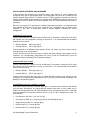
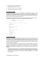
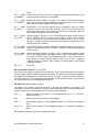
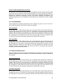
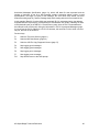
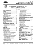
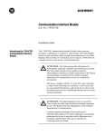
Hardware Requirements
If a PLC-5 is to be used, SB can run on an Allen-Bradley 1771-DXS2 Information Processor
using a PC Flash EPROM card. If SB is to operate on the DH+ network, the 1771-DXS2 must be
connected to a 1771-DXKT adapter, see figure 1 (a). The adapter includes an 1784-KT/B DH+
interface and a 1784-CP8 adapter for the DH+ cable. This hardware and software package can
be supplied, configured and ready to go, from Merrick. To utilize the DH485 network, an AllenBradley 1747-PIC module must be purchased. This can also be supplied by Merrick.
SB also runs on the Allen-Bradley 1771-EIP, using two PC cards: a Flash EPROM card and a
PCMK/B DH+/DH485 adapter. Also this hardware and software package can be supplied from
Merrick. This configuration has the advantage of taking up only one slot in the PLC-5.
A general version is also available, which will run on a personal computer, at least 386/25, with 2
Mbytes of RAM, 5 Mbytes of Hard Disk space and two available serial ports. This is shown in
figure 1 (d). One serial port must either be a RS-422 port, or an adapter must be used to convert
RS-232C signal levels to RS-422. To operate on the DH+ network, the PC has to be equipped
with an Allen-Bradley 1784-KT/B or 1771 KTX adapter, serving as an interface between the PC
ISA bus and DH+, and an Allen-Bradley 1784-CP8/A adapter, connecting the DH+ cable to the
1784-KT/B. This configuration is demonstrated in figure 1 (c).The DH+ equipped computer only
requires one serial port, COM1 or COM2. To operate on the DH485 network, a 1747-PIC module
must be purchased, see figure 1 (b).
Some common arrangements can be seen below.
possible combinations.
Please note that these are not the only
MMI Package
(optional)
PLC-5 chassis
P
L
C
5
D
X
S
2
K
T
SLC500
PIC
DH+
IBM compatible
w/ KT Card
RS-422
DH485
IBM compatible
PLC
RS-422
M
C
M
C
M
C
M
C
M
C
M
C
M
C
(a)
M
C
(b)
PLC-5
or
SLC5/04
DH+
IBM compatible
w/ KT Card
PLC
RS-422
PLC-5
or
SLC500
DF1
IBM compatible
PLC
RS-422
M
C
M
C
M
C
M
C
(c)
A-B SuperBridge Technical Reference
M
C
M
C
M
C
M
C
(d)
2
SETTING UP A SYSTEM
Setting up a SB system includes the following steps:
1. Verify that existing MCs are equipped with a RS-485 Serial Ports and have software
application versions listed in Model Specific Information (page 27). If not, complete and/or
upgrade.
2. If an A-B 1771-DXS2 processor is used, locate a PLC-5 to serve as a host for the 1771DXS2 Information Processor and 1771-DXKT adapter (if applicable). Two slots must be free,
and the power supply must be able to handle an additional 5V load of 1.6 A, -12V load of
0.04 A, and a +12V load of 0.04A. Install according to instructions in [1], page 2-2.
3. If an A-B 1771-EIP processor is used, locate a PLC-5 to serve as a host for the 1771-EIP
Information Processor. One slot must be free, and the power supply must be able to handle
an additional 5V load of 2.2 A, -12V load of 0.04 A, and a +12V load of 0.04A. Install
according to instructions in [8].
4. If a generic personal computer (PC) will be used, make sure all required hardware is
installed. This may include a 1784-KT/B or 1784-KTX card, and a RS-422 adapter. See
Install the KT Card (page 4), or Install the KTX Card, if used (page 4) and Install RS-422
converter or adapter, if needed (page 4).
5. Copy the SB software files to the PC hard disk and modify the PC configuration files if
necessary. See Modify PC configuration (page 5).
6. Assign a DH+ or DH485 station number for SB. See Assign Station Numbers (page 9).
7. Verify that SB starts up properly in the PC. See Verify SB startup (page 9).
8. Connect all MCs to SB. See MC Physical Connection (page 10).
9. Set up communication parameters in all MCs connected. See Setting Up communications
with the MCs (page 10).
10. Configure SB for the number of MCs connected. See SB Configuration for MCs (page 11).
11. Verify that communications with the MCs work properly. See Verify MC communication (page
11).
12. If data is to be copied from SB to one or more PLC, the file copy scheme must be set up and
verified. Use the steps 13..16.
13. Allocate memory files in the PLC(s) to hold SB data. See Allocating A-B files (page 12).
14. Configure SB to read and write the A-B files. See SB Configuration for File Copy (page 12).
15. Connect SB to your DH+ or DH485 network. See Connecting SB to DH (page 13).
16. Verify that the file copy process works properly. See Verify A-B File Copy (page 13).
17. If SB is to service PLC-2 type Unsolicited Messages, that is, act as a PLC-2 with respect to a
MMI or other PLCs on the DH+ network, some PLC-2 parameters have to be set-up. See
Setting up PLC-2 Compatible parameters (page 13).
18. Verify that the Superbridge version is compatible with the MC application software version.
See Superbridge /MC Software Version Compatibility Table in Error! Reference source not
found. on page Error! Bookmark not defined..
A-B SuperBridge Technical Reference
3
INSTALLING SB SOFTWARE AND HARDWARE
If SB hardware and software are purchased entirely from Merrick, it comes installed and
configured along with a specification sheet. The configuration may have to be altered as the
system changes. When an A-B 1771-DXS2 or A-B 1771-EIP Information Processor is used, the
software and configuration files resides on a PCMCIA Flash EPROM card. Merrick has to do the
installation for the 1771-DXS2, since a BIOS upgrade in the 1771-DXS2 Information Processor is
necessary.
SB will run on a generic PC according to Hardware Requirements (page 2). If configuration data
was available to Merrick before the time of shipment, the configuration file has already been
prepared. In any case, a specification sheet is always shipped, indicating the current
configuration.
Install the KT Card, if used
Configure and install the 1784-KT/B card in the SB host PC, according to instructions in [2]. Since
SB normally is the only application running on the host PC, it is recommended that the default
settings are used, that is,
•
Memory address:
D400 ([2], page 8)
•
Interrupt Setting:
IRQ 5. ([2], page 9)
This corresponds to an address switch setting of {Down, Up, Down, Up, Down, Down}, and the
Interrupt jumper in the center position.
If there are other devices that may cause a conflict with these settings, other settings can be
examined. The corresponding configuration files (CFG_KT.INI and CONFIG.SYS) must me
altered accordingly. See Modify PC configuration (page 5).
Install the KTX Card, if used
Configure and install the 1784-KTX card in the SB host PC, according to instructions in [9]. Since
SB normally is the only application running on the host PC, it is recommended that the default
settings are used, that is,
•
Memory address:
D700 ([9], page 2-3)
•
Interrupt Setting:
IRQ 5. ([9], page 2-7)
If there are other devices that may cause a conflict with these settings, other settings can be
examined. The corresponding configuration file (CFG_KT.INI) must me altered accordingly. See
Modify PC configuration (page 5).
Install RS-422 converter or adapter, if needed
If the host PC does not have a RS-422 serial port, a converter between RS-232 and RS-422
must be used. Alternatively, an internal RS-422 adapter board may be used. Make sure to
disable the corresponding RS-232 COM port!Merrick has successfully tested the ULTRA-485
serial port adapter from Industrial Computer Source, (619) 677 0877. Strappings for COM 1 for
this board are:
•
Port Adress to 3F8. SW1 = {On, On, On, Off}
•
IRQ Jumper to IRQ4. E1 = {Jumper @ 4} Do not use IRQs higher than 7.
•
Single Interrupt mode. E2 = {Jumper @ N}
•
RS-422 mode. E5 = {Jumper @ 422}
•
RS-422 mode. E3 = {Jumper @ 422}
A-B SuperBridge Technical Reference
4
•
SIO-485 Mode. E4 = {Dip Shunt @ SIO-485}. This is not the default setting.
•
Line terminations on. SW-2 = {(T,P,P,L,L) = (On, On, On, Off, Off)}.
For COM2, the following strappings would change to:
•
Port Adress to 2F8. SW1 = {On, On, Off, On}
•
IRQ Jumper to IRQ3. E1 = {Jumper @ 3}.
Install RS-422 multiport adapter, if needed
If more than 32 MCs are connected to the host PC serial port, or to increase performance, a
multi-port RS-422 adapter must be used. Up to 4 serial ports, sharing a single interrupt (IRQ), are
supported.
Merrick has successfully tested the FASTCOM422/4 serial multiport adapter from Industrial
Computer Source, (619) 677 0877. Strappings tested for this board were:
•
Port Adress Base to 280. SW1 = {On, On, Off, On, Off, On, On, On}
•
IRQ 3, No IRQ Sharing. SW2 = {On, Off, On, Off, Off, Off, Off, Off}, SW3 = {Off, Off, Off, Off}.
This is not the factory default setting. The factory default is IRQ5. In the test computer, IRQ5
was used by the A-B KT adapter. No COM2 port, which uses IRQ3, was installed in the test
computer. Do not use IRQs higher than 7.
•
CTS Handshaking disabled, No RTS Tx driver control. SW4 = {On, On, On, On, Off, Off, Off,
Off}.
An example of the configuration file for this multiport adapter an be found in Sample
SUPERB.INI, page 46.
Modify PC configuration
The SB software files are distributed as a complete directory structure, including all configuration
files. If a 1771-DXS2 or 1771-EIP information processor is used, all files reside on a PCMCIA
Flash EPROM card, drive C:. For a pre-configured system, the files are installed along with MSDOS on the PC hard drive. In all other cases, the SB files are shipped on a 3½” floppy, and the
files have to be copied onto the PC hard drive. MS-DOS, versions 5 or 6, must already be
installed. To copy the SB files onto the hard drive insert the distribution diskette in the floppy drive
(assumed to be drive A:), boot the PC, and at the C:\> prompt, type
XCOPY A:*.* /S /E /V
and hit return. The existing AUTOEXEC.BAT and CONFIG.SYS files will be overwritten and the
following directories will be created:
\SUPERB
SB executable and configuration files
\ABIC\BIN
KT card executables and configuration files
\IPDS\SYMBOLS
A-B 6200 programming software symbol files for SB, if configured
\DOC
Specific release or configuration text files.
MS-DOS files are assumed to reside in \DOS.
Four files deals with the SB configuration and are referenced below as
CFG_KT.INI
\ABIC\BIN\CFG_KT.INI
SUPERB.INI
\SUPERB\SUPERB.INI
AUTOEXEC.BAT
\AUTOEXEC.BAT
A-B SuperBridge Technical Reference
5
CONFIG.SYS
\CONFIG.SYS
They can all be edited with the MS-DOS editor ‘EDIT’.
The default CFG_KT.INI file is seen below. It is configured for DH+ communication using a KT
Card.
;
CFG_KT.INI
;
SuperBridge Default KT Configuration
;
10/10/95/LTM
[DTL_KT.1]
DEVICE=KT
MEMORY=D400
IRQ=5
STATION=71
NAME=SUPERB
TERMINATION=OFF
Entries in CFG_KT.INI are
[DTL_p.n]
Device definition statement. Protocol designators (p) can be KT, 485, or
DF1 depending on communication method used. Pushwheel numbers
(n) may range from 1 to 8. Each communication interface module must
have a unique pushwheel number.
DEVICE=KT
Must be present if KT Card is used to interface with DH+.
MEMORY=D400
Must correspond to the memory address DIP switch setting on the KT
card. D400 is the default. See Install the KT Card (page 4).
IRQ=5
Must correspond to the position of the IRQ jumper on the KT card. 5 is
the default. See Install the KT Card (page 4).
STATION=71
This is the station number for SB. See Assign Station Numbers (page 9)
NAME=SUPERB
This is the name that will appear on DH+ for SB. Running a DH+
interrogation software, such as A-B ‘WHO’ will show this name. If more
than one SB is connected to DH+, it is a good idea to edit this name.
TERMINATION=OFF
If SB is connected at the end of the DH+ network and no terminating
resistor in installed, set this entry to “YES”. See [3], page 11-1.
The following is an example of a CFG_KT.INI file that is configured for DH+ communication using
a KTX Card.
;
CFG_KT.INI
;
SuperBridge Default KTX Configuration
;
03/07/98/LTM
[DTL_KT.1]
DEVICE=KTX
PROTOCOL=DHPLUS
MEMORY=D700
IRQ=5
STATION=71
NAME=SUPERB
TERMINATION=OFF
Entries in CFG_KT.INI are
[DTL_p.n]
Device definition statement. Protocol designators (p) can be KT, 485, or
DF1 depending on communication method used. Pushwheel numbers
(n) may range from 1 to 8. Each communication interface module must
have a unique pushwheel number.
A-B SuperBridge Technical Reference
6
DEVICE=KTX
Must be present if KTX Card is used to interface with DH+.
MEMORY=D700
Must correspond to the memory address DIP switch setting on the KTX
card. D700 is the default. See Install the KTX Card, if used (page 4).
IRQ=5
Must correspond to the position of the IRQ jumper on the KTX card. 5 is
the default. Install the KTX Card, if used (page 4).
STATION=71
This is the station number for SB. See Assign Station Numbers (page 9)
NAME=SUPERB
This is the name that will appear on DH+ for SB. Running a DH+
interrogation software, such as A-B ‘WHO’ will show this name. If more
than one SB is connected to DH+, it is a good idea to edit this name.
TERMINATION=OFF
If SB is connected at the end of the DH+ network and no terminating
resistor in installed, set this entry to “YES”. See [3], page 11-1.
The following is an example of a CFG_KT.INI file that is configured for DH485 communication
using a PIC Module.
;
CFG_KT.INI
;
SuperBridge DH485 Configuration
;
11/30/95/BPM
[DTL_485.2]
DEVICE=PIC
BAUD=19200
IRQ=4
COM_PORT=1
STATION=22
MAXNADDR=037
NAME=SB_485
Entries in CFG_KT.INI are
[DTL_p.n]
Device definition statement. Protocol designators (p) can be KT, 485, or
DF1 depending on communication method used. Pushwheel numbers
(n) may range from 1 to 8. Each communication interface module must
have a unique pushwheel number.
DEVICE=PIC
Must be present if DH485 network, which requires PIC Module, is to be
used.
BAUD=19200
The transmission rate of the DH485 link. The choices available are:
300, 1200, 2400, 4800, 9600, and 19,200 bps.
IRQ=4
Must correspond
communication.
COM_PORT=1
COMM port to be used for DH485 communication.
STATION=22
This is the station number for SB. See Assign Station Numbers (page 9)
MAXNADDR=037
The maximum node address is the highest station number used on the
DH485 link. The number can range from 000 to 037 octal.
NAME=SB_485
This is the name that will appear on DH485 for SB. Running a DH485
interrogation software, such as A-B ‘WHO’ will show this name. If more
than one SB is connected to DH485, it is a good idea to edit this name.
to
the
COMM
port
being
used
for
DH485
The following is an example of a CFG_KT.INI file that is configured for DF1 communication.
;
CFG_KT.INI
A-B SuperBridge Technical Reference
7
;
SuperBridge DF1 Configuration
;
11/30/95/BPM
[DTL_DF1.3]
DEVICE=DF1
BAUD=19200
IRQ=4
COM_PORT=1
NAME=SB_DF1
ERROR=0
PARITY=0
DUPLEX=1
Entries in CFG_KT.INI are
[DTL_p.n]
Device definition statement. Protocol designators (p) can be KT, 485, or
DF1 depending on communication method used. Pushwheel numbers
(n) may range from 1 to 8. Each communication interface module must
have a unique pushwheel number.
DEVICE=DF1
Must be present if DF1 communication is to be used.
BAUD=19200
The transmission rate of the DF1 link. The choices available are: 300,
1200, 2400, 4800, 9600, and 19,200 bps.
IRQ=4
Must correspond to the COMM port being used for DF1 communication.
COM_PORT=1
COMM port to be used for DF1 communication.
NAME=SB_DF1
The name of the communication interface module that appears in the
active nodes list.
ERROR=0
Specifies the type of error detection used by the DF1 protocol. Choices
are: 0 (BCC) and 1 (CRC).
PARITY=0
Specifies the parity for the DF1 protocol. Choices are: 0 (None) and 1
(Even).
DUPLEX=1
Specifies full duplex. Do not edit.
For more detailed information on the configuration of CFG_KT.INI, see [7], pages 3-3 & 3-4.
SUPERB.INI, with its many configuration entries, is described in detail in Configuration (page 41).
The default AUTOEXEC.BAT is shown below, it is configured for DH+ communication using a KT
Card.
REM
AUTOEXEC.BAT
REM
SuperBridge Default KT Configuration
REM
10/10/95/LTM
PATH=C:\DOS;C:\ABIC\BIN;C:\SUPERB
SET ABIC_CONFIG=C:\ABIC\BIN
C:\ABIC\BIN\DTL_KT
C:\ABIC\BIN\CFG_KT
C:\ABIC\BIN\RNATSR
C:\ABIC\BIN\RNA -a8
CD SUPERB
ABDRV
There is normally no reason to alter this file if DH+ communication is to be used.
The following is an example of AUTOEXEC.BAT configured for DH485 communication.
REM
AUTOEXEC.BAT
REM
SuperBridge DH485 Configuration
REM
11/30/95/BPM
PATH=C:\DOS;C:\ABIC\BIN;C:\SUPERB
SET ABIC_CONFIG=C:\ABIC\BIN
C:\ABIC\BIN\DTL_485
A-B SuperBridge Technical Reference
8
C:\ABIC\BIN\CFG_485
C:\ABIC\BIN\RNATSR
C:\ABIC\BIN\RNA -a8
CD SUPERB
ABDRV
There is normally no reason to alter this file if DH485 communication is to be used.
The following is an example of AUTOEXEC.BAT configured for DF1 communication.
REM
AUTOEXEC.BAT
REM
SuperBridge DF1 Configuration
REM
11/30/95/BPM
PATH=C:\DOS;C:\ABIC\BIN;C:\SUPERB
SET ABIC_CONFIG=C:\ABIC\BIN
C:\ABIC\BIN\DTL_DF1
C:\ABIC\BIN\CFG_DF1
C:\ABIC\BIN\RNATSR
C:\ABIC\BIN\RNA -a8
CD SUPERB
ABDRV
There is normally no reason to alter this file if DF1 communication is to be used.
This is the default CONFIG.SYS
REM
CONFIG.SYS
REM
SuperBridge Default 0.99
REM
01/07/97/LTM
BUFFERS=15,0
FILES=8
DEVICE=C:\DOS\INTERLNK.EXE
The INTERLNK driver load (last line) is always attempted. It will fail if no Interlink server PC is
connected to COM1 or COM2. This is for the benefit of PC card Flash EPROM disk installations.
The intersvr/interlnk utilities is the only way to transfer files to and from the SB host PC.
SB will always start at boot, showing its home screen. To be able to edit configuration files, exit
SB by pressing F10.
Assign Station Numbers
SB will act as a PLC-5 or SLC500 on Data Highway communication networks. As such, it must
be assigned an A-B style octal station number. The station number is defined in CFG_KT.INI.
Default is 71 (octal), which is for DH+ communication. The DH485 network is limited to address
37 octal. Check that there are no station number conflicts on the Data Highway network, and edit
CFG_KT.INI if needed. If more than one SB resides on the Data Highway network, at least one if
the station numbers have to be altered. See Modify PC configuration (page 5).
Verify SB startup
Connect a VGA monitor and PC keyboard to the SB host PC and reboot. Watch for error
messages as the communication drivers load and SB starts up. The load process can be made to
run step-by-step by holding down the F8 key immediately after boot. If SB starts successfully, the
SB home screen will appear.
If possible, run “WHO” or “SUPER WHO” on another device on the DH+ network. With the default
settings, SB should appear as a “TERM” device with Station Number 71, name SUPERB.
A-B SuperBridge Technical Reference
9
SETTING UP COMMUNICATIONS WITH THE MCS
The MC network is a four wire RS-485 Master-Slave polled communications loop. All MCs are
slaves on the network, and are required to have a RS-485 serial port and a unique address,
called “Controller Number” (CN). The CN is set up, along with other serial communications
parameters, in each MC. SB is the master, and must have either a four wire RS-485 or a RS-422
serial port.
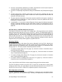
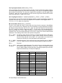
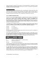
MC Physical Connection
Use a RS-422 type two pair shielded cable like Belden 9368. One pair is used to carry signals
from the SB transmitter to all MC receivers. The other pair is used to carry signals from all MC
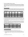
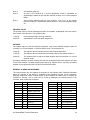
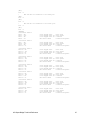
transmitters to the SB receiver. The following table lists connections, using an A-B 1771 DXS2
Information Processor port, strapped for RS-422 communications. Other RS-422 adapters may
have other pinouts.
SB
Signal
Tx+
TxRx+
RxShield
SB 1771
DXS2 Pin #
(DE-9 P)
1
9
2
6
5
ULTRA
-485 Pin #
(DB-25P)
24
25
12
13
7
FASTCOM
422/4 Pin #
(DE-9 S)
4
5
8
9
1
MC³
Controller
Terminal #
3
4
1
2
N.C.
MC² Controller
Pin #
(DB-25S)
22
23
24
25
11
MC
Signal
Rx+
RxTx+
TxShield
Be careful when running the cable. Avoid power lines and other devices that might cause
electrical disturbances. Maximum cable length is 1230 m (4000 ft). See also [1], pages 3-2 and
D-1. SB does not have to be connected at one end of the cable. Remove all termination resistors
in the MC² serial ports. Add a 150Ω terminating resistor between the + and - lines for each pair at
each end of the cable.
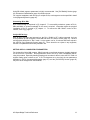
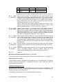
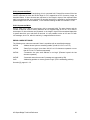
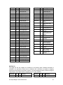
If only one MC² is used, it is possible to use a RS-232 interface instead. This is useful for benchtesting SB, using a regular office PC, which normally has no RS-422 interface. The cable should
have a DE-9S, for a 9 pin connector in the PC or a DB-25S, for a 25 pin connector in the PC in
the PC end and a DB25P in the MC end. Use the following table for the pinout, and keep the
cable length less than 25 feet at 19200 baud.
Signal, PC side.
Rxd (PC Receiver)
Txd (PC Transmitter)
Ground
Shield
PC COM port,
9 pin (DE-9P)
2
3
5
1
PC COM port,
25 pin (DB-25P)
3
2
7
1
MC² Serial port
(DB-25S)
15
12
7
1
MC Communication Parameters
MC Communication parameters are set in the controllers themselves. They are:
1. Controller Number. Must be different for each controller. Start with 1 and continue up.
2. Baud Rate. Must be the same for all controllers. Set to the highest possible, normally 19200.
Some older software versions only support up to 9600 baud. See Model Specific Information
(page 23).
A-B SuperBridge Technical Reference
10
3. Parity. Must be set to “NO Par” in all MCs.
4. Data Bits. Must be set to 8 in all MCs.
5. Start character. Must be set to 10 in all MCs.
6. End character. Must be set to 13 in all MCs.
SB Configuration for MCs
SB configuration parameters are set in SUPERB.INI. See Configuration (page 41) At least
Controllers in the [Sizes] Section (page 41) must be set. The rest of the parameters could
normally be left at their default settings. Note that the CN is defaulted to Controller Index + 1.
Controller Index always starts at zero and increments up by one per connected controller. CNs
start at 1 and can have any numerical value up to 57.
See examples in [PortN] Sections (page 41) on how to use different COM ports and how to
change the default baudrate from 19200. The default SUPERB.INI looks like this:
;
;
;
SUPERB.INI
SuperBridge for Allen-Bradley Default
09/11/96/LTM
[SIZES]
;
One serial port, five MCs, no file copy to PLC
ComPorts = 1
Controllers = 5
Segments = 0
[IRQ]
;
Settings for COM2
PortVector = 0B
PIDMask = 08
[PORT0]
;
COM2, 19200 Baud
UartBase = 2F8
DlabReg = 0006
[PLCDEFAULT]
DefaultStation = 60
[PLC2DATA]
PLC2ReverseFloat = 0
Verify MC communication
With all MCs connected and powered up, reboot SB and check The Home Screen (page 31). All
MCs should be in “Run” mode and identified by model and version. An “Unknown” MC in the
home screen has never been successfully contacted by SB. Let the system run for 15 minutes
and check communications error statistics for each MC in the MC Data Screen (page 32). There
should be no fatal errors and less than 100 communication errors. If the error rates are higher,
check your cable and connections.
MC² controllers have indicators on the serial ports that can help troubleshoot communication
problems. A yellow light blinks as telegrams are received by the MC². A green light blinks as
telegrams are transmitted back to SB. Newer MC models also have serial communications
diagnostic screens, usable for troubleshooting. Here is a checklist that can be used if there are
problems:
1. If a regular PC COM port is used, it can be tested by disconnecting the cable and short pins 2
and 3 (for both 9 pin and 25 pin connectors), while looking at the MC Combined Diagnostic
Screen (page 34). While the pins are shorted, the “CsumErrs” parameters in row 7 should
increment rapidly. When the short is opened, the “Timeouts” parameter in row 7 should
increment slowly.
A-B SuperBridge Technical Reference
11
2. Check all communication parameters in all MCs. All parameters must be equal except the
“Controller Number”, which must be different for all MCs.
3. Check the corresponding line parameter settings in SUPERB.INI. See [PortN] Sections (page
41).
4. All MC²s should show a blinking yellow light on the serial port, indicating that they are
receiving telegrams from SB. If it does not blink at all, there are problems with the cable, SB
serial port or RS-422 converter.
5. The green light should also blink. If there are more than one MCs in the system, it should not
blink as often as the yellow light. If it does not blink at all, there are problems with the line
parameters or controller number.
6. A LastFatalErr of -13 in the MC Combined Diagnostic Screen (page 34) indicates that the MC
actually is returning telegrams, but the model and/or version is not supported by SB. An
upgrade of either SB or the MC software version may be necessary. See Supported functions
(page 23).
SETTING UP PLC CONTROLLERS FOR FILE COPY
If MC data in SB files are to be used in PLC ladder logic, a file copy scheme can be enabled,
where SB writes and reads files from one or more PLCs. See PLC File Specification (page 14).
Typically, one PLC is the host for SB, holding master versions of the two control files that are red
by SB (N13 and F15). The host PLC normally also holds copies of the two report files that are
written by SB (N12 and F14). In some installations several PLCs serve as hosts for MCs, and
the files are split between them. File copy is always attempted, solicited from SB, when the
Segments entry in the [Sizes] Section (page 41) is greater than zero.
Allocating A-B files
For successful file copy to take place, files must be allocated in the host PLCs. Normally two
integers (N) and two floating points (F) files are created. File sizes are dependent on the number
of MCs connected, see Controllers entry in the [Sizes] Section (page 41). To allocate PLC files,
See [4], page 10-1. File sizes (number of elements) should be at least
•
For copies of Integer Report File, N12 (page 14), 8 times the number in Controllers entry in
the [Sizes] Section (page 41).
•
For master versions of Integer Control File, N13 (page 16), 7 times the number in Controllers
entry in the [Sizes] Section (page 41).
•
For copies of Floating Point Report File, F14 (page 18), 8 times the number in Controllers
entry in the [Sizes] Section (page 41).
•
For master versions of Floating Point Control File, F15* (page 19), 3 times the number in
Controllers entry in the [Sizes] Section (page 41).
*Note: Only SLC5/03 and SLC5/04 versions support floating point files and data transfer.
The PLC host files do not have to be N12, N13, F14 and F15, but they have to be the same
category (N and F files). It is a good idea to use the SB file names (N12, N13, F14 and F15) if
they are free in the host PLC; it makes PLC programming easier, using this manual.
SB Configuration for File Copy
File copy is enabled by setting entries in SUPERB.INI. A Segments entry in the [Sizes] Section
(page 41) greater than zero enables file copy. Normally, four segments per five MCs are used.
A-B SuperBridge Technical Reference
12
Using SB default segment parameters is highly recommended. See [PLCDefault] Section (page
43). At least the DefaultStation (page 43) needs to be set.
For complex installations with file copy to multiple PLCs, each segment can be specified in detail
in the [SegmentN] Section (page 44).
Connecting SB to DH+
DH+ network design is explained in [5], chapter 5. To successfully maintain a system of PLCs,
SBs and MMIs, a general knowledge in this area is required. Information about the physical
installation of DH+ is covered in [3], chapter 11. To connect the SB 1784-KT card to a DH+
network, refer to [2], page 12.
Verify A-B File Copy
With all MCs connected and powered up, the DH+, DH485 or DF1 cable connected, the host
PLCs powered up and configured, reboot SB and check The Home Screen (page 31). All MCs
and segments should be in “Run” mode. Let the system run for 15 minutes and check rejects in
the A-B File Copy Diagnostic Screen (page 37). There should be no rejects in any segments,
and the Time parameter should stay less than 160.
SETTING UP PLC-2 COMPATIBLE PARAMETERS
For the benefit of older MMI systems, SB will respond to unsolicited telegrams originally designed
for the A-B PLC-2 controller. Some parameters need to be set to cover compatibility issues,
using this method. Especially handling floating point numbers is difficult, since the PLC-2 did not
support floating point numbers at all. If PLC-2 telegrams are to be used, the two parameters
described in PLC-2 Unprotected Messages (page 21) and the [PLC2DATA] Section (page 45)
may have to be changed from their defaults.
A-B SuperBridge Technical Reference
13
PLC FILE SPECIFICATION
MC Data in SB is available in PLC style files. They are:
•
N12, containing read-only bit or integer oriented data from the MCs, such as inputs, outputs,
alarms and communication status. In N12, there are eight words per connected MC.
•
N13, containing read-write bit or integer oriented data for the MCs, containing parameter tags
and function requests. In N13, there are seven words in per connected MC.
•
F14*, containing read-only floating point data from the MCs, such as tagged parameters,
feedrates and totals. In F14, there are eight floats per connected MC.
•
F15*, containing read-write floating point data for the MCs, such as setpoints. In F15, there
are three floats per connected MC.
*Note:
Only SLC5/03 and SLC5/04 versions support floating point files and data
transfer.
Note:
Italic names indicate recommended symbol names in A-B ladder logic. x is a
representation of the controller index, starting with A for the MC with controller
index 0, continuing with B for controller index 1 etc. Under certain circumstances,
Merrick will supply a RxLogix programming software symbol table file with the
distribution diskette.
Integer Report File, N12
SuperBridge will maintain a PLC type integer file, with 8 integers per connected MC. The purpose
of this file is to make bit or integer data available to the PLC ladder or MMI programmer. The file
is read only. The file name is N12.
The following is a specification of the 8 words belonging to a certain MC.
MC Status Word, N12:0,8,16..(x_STATUS)
The MC Status word indicates the operative status of the controller. Any bit set indicates a
potential problem. The bits are mapped as follows:
Bit 0 (0001)
(x_OFFLINE)
Off-line. The MC is taken off-line by the Off-line bit in the MC Control Word. If
the Off-line bit in the MC Control Word, N13:4,11,18.. (page 17) is cleared (by
the PLC or Control Room Software) this bit is cleared and the MC Status will
change to "Reviving".
Bit 1 (0002)
(x_COLDST)
Coldstart. The MC has been cold-started, and is in the process of being brought
on-line for normal operation.
Bit 2 (0004)
(x_COMERR)
Communications failure. The MC fails to respond to communications. Attempts
are made periodically to revive the MC. During the revival attempt time, this bit
is cleared and the MC status changes to "Reviving".
Bit 3 (0008)
(x_REVIVE)
Reviving. An attempt is made to make the MC go on-line, either by a revival
attempt from a communications failure or a change of state to 0 of the MC
Control Word Off-line bit. When the revival attempt is concluded, this bit is
cleared and the MC state changes to either "Coldstart", "Communications
failure" or "On-line".
Bit 4 (0010)
(x_SETON)
Always on. This bit is set every time a file copy takes place. It coulb be
periodically cleared by the ladder logic and then checked to see that it is set by
SB. This would ensure that communication between SB and the PLC has not
A-B SuperBridge Technical Reference
14
failed.
Bit 5 (0020)
(x_INMENU)
In menu. The MC menu system is engaged. This means that the effect of any
remote keycode requests are unpredictable.
Bit 6 (0040)
(x_STARVE)
Material starvation condition. The MC is in a state of low feedrate deviation
alarm. Only MCs that supports feedrate can have this bit set. It can be used to
take action on a feeder material starvation condition.
Bit 7 (0080)
(x_RECAL)
Recalibration. The MC has possibly been re-calibrated, since the rerate,
calibrate or service menu has been accessed. This bit is set until the MC has
been interrogated about scale factors and decimal point settings. When the
interrogation is completed, the bit is cleared.
Bit 8 (0100)
(x_INTSP)
Internal Setpoint. The MC is not in communications setpoint mode. Setpoint
values in SetPoint, F15:0,3,6.. (page 19) is ignored by the MC. This bit is never
set for MCs that do not support external setpoint, such as the 11.00.HP.
Instead, a “setpoint” setting us used for other purposes for these models. See
Setpoint (page 24) for details.
Bit 9 (0200)
(x_TAGERR)
Tag Access problem. A register, tagged for continuous reporting, is either nonexistent or read protected. Also, indication of difficulties downloading setpoints
to the controller.
Bit 10 (0400)
(x_INTSEC)
Internal Secondary Setpoint. The MC is not in communications setpoint mode
for the secondary setpoint. Secondary setpoint values in Secondary SetPoint,
F15:2,5,8..(x_SECPT) (page 19) is ignored by the MC. This bit is never set for
MCs that do not support external setpoint, such as the 11.00.HP. Instead, a
“setpoint” setting us used for other purposes for these models. See Setpoint
(page 24) for details.
Bit11 - 15
Reserved.
MC Internal State, N12:1,9,17..(x_INTSTA)
MCs with an internal state machine, such as 30.00.HP, 30.10.EX and 35.00.HP have an internal,
numeric integer variable, describing its operational state. The value of this variable is available in
this integer. For models that are continuous, such as 10.00.HP, 11.00.HP, 20.00.HP and 22.00,
this value is always 0. The interrogation of this variable is a part of the fast loop. To find out about
the internal state values, see Internal State, (page 27).
MC Digital I/O, N12:2,10,18..(x_DIGIO)
The states of the physical inputs and outputs of the MC are available in this integer. The
interrogation is a part of the fast loop. To find out about digital input and output designations, see
Digital I/O (page 25). The MC physical I/O is mapped to the following bits:
Bit 0 - 6
State of physical (relay) outputs 1..7 at backplane board #1. A "1" indicates a
closed relay output.
Bit 7
Reserved. The state of this bit is unpredictable.
Bit 8 - 11
State of physical inputs 1..4 at backplane board #1. A "1" indicates a closed input
circuit.
Bit 12 - 15
State of physical inputs 1..4 at backplane board #2. A "1" indicates a closed input
circuit.
Note that MC² controllers only have one backplane board.
A-B SuperBridge Technical Reference
15
MC General Alarms or Warnings, N12:3,11,19..(x_ALARMS)
Any current general alarms or warnings in the MC is visible as a bit in this integer. MCs have a
maximum of 16 general alarms or warnings. There is one bit per alarm. The interrogation is a part
of the fast loop. To find out about MC general alarms and warnings, see General Alarms (page
24).
Request Done Bits, N12:4,12,20..(x_REQDONE)
This integer contains the "Done" bits for requests set by the user in the MC Request Word. The
Done bits are always set when a request has been completed. If the request caused an error, the
Request Error Bits, N12:5,13,21..(x_REQERR) will indicate what kind of errors that were
encountered. The bits are mapped in the same way as the bits in the MC Control Word,
N13:4,11,18.., (page 17). The done bits for Download Setpoint, and Download Secondary
Setpoint are set at the first successful setpoint download, and remain set until the request bit is
cleared, or a problem occurs. Setpoints are continuously downloaded, when they change.
Request Error Bits, N12:5,13,21..(x_REQERR)
This integer contains the "Error" bits for the last request executed in the MC Request Word. If no
errors were encountered, all bits are cleared. The bits are mapped as follows:
Bit 0 (0001)
(x_RQEOFL)
MC is off-line or in communications failure. Request could not be performed.
Bit 1 (0002)
(x_RQENOS)
The request is not supported for this MC model.
Bit 2 (0004)
(x_RQEACC)
No access. The requested function could not be performed because of access
restrictions.
Bit 3 (0008)
(x_RQEKEY)
Keyboard problems. A remote keyboard request was issued when the MC was
not in root node. No remote keystroke was sent.
Bit 4 (0010)
(x_RQEREG)
A register number is addressed that does not exist in the MC model.
Bit 5 (0020)
(x_RQEVAL)
The value used for updating a register is too large to fit in the actual register
type.
Bit 6 - 15
Reserved.
Request Integer Result, N12:6,14,22..(x_INTRES)
This integer contains the result of a request for integer data. Data is valid when the
corresponding Request Done bit is set and all Request Error Bits are cleared. Interpretation is
dependent on which request was posted. See MC Control Word, N13:4,11,18.. (page 17), for
details.
External Outputs, N12:7,15,23..
Logical outputs in some MC³ controllers can be mapped to up to 16 external outputs. They
appear as bits in this word. External output 1 corresponds to bit 0 etc. This is useful when a
physical output is not needed at the MC location, but must be monitored by the PLC.
Integer Control File, N13
SuperBridge will maintain another PLC type integer file, with 7 integers per connected MC. The
purpose of this file is to make it possible for the PLC ladder or MMI programmer to control the
SuperBridge or MC operation. The file has read and write access. The file name is N13.
The following is a specification of the 7 words belonging to a certain MC.
A-B SuperBridge Technical Reference
16
Fast Tag Register Number, N13:0,7,14..(x_FTAG)
This is a numerical value of a register number in the MC. To find out about MC register numbers,
see Useful Registers (page 29). If the value of this integer is not zero, the corresponding register
will be polled in the fast loop. The value of the register will be available in the Fast tagged value,
F14:0,8,16.. (page 19), as long as the MC is on-line and the Tag Access Problems bit in the MC
Status Word, N12:0,8,16.. (page 14) is not set.
Slow Tag Register Number 1 - 3 N,13:1-3,8-10,15-17..(x_STAG1, x_STAG2, x_STAG3)
These integers work just like the Fast Tag Register Number, but the corresponding registers will
be polled in the slow loop. The value of the register will be available in Slow tagged values 1 - 3,
F14:1-3,9-11,17-19.. (page 19), respectively.
MC Control Word, N13:4,11,18..(x_CONTROL)
The bits in this integer are used to control status and issue function requests to SuperBridge.
There is one function per bit. Requests may be accompanied by request parameters located in
MC Request Integer Parameter N13:5,12,19.. (page 18) and/or MC Request Float Parameter,
F15:1,4,7.. (page 19). Setting a Request bit (Bit 4 - 15) will result in the corresponding bit in
Request Done Bits, N12:4,12,20.. (page 16) being set, when the request either has completed or
caused an error. Only one request should be run at a time, in order not to confuse done bits and
parameters. The following control status and requests are supported:
Bit 0 (0001)
(x_ROFFL)
MC Off-line. Setting this bit will take the corresponding MC off-line. When done,
the MC Status Word, N12:0,8,16.. (page 14), Bit 0, Off-line, will be set. Clearing
this bit bill bring the MC on-line again. It is a good idea to set a MC that is
currently not used off-line, since this speeds up the polling loops.
Bit 1 (0002)
(x_RDLSET)
Download setpoints. This bit will cause any value (including zero) in SetPoint,
F15:0,3,6.. (page 19) to be continuously downloaded as a setpoint to the MC.
Bit 2-3
Reserved.
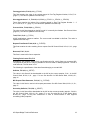
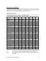
Bit 4 (0010)
(x_RKEY)
Send remote keyboard keycode. The code for the key must be present in the
MC Request Integer Parameter N13:5,12,19.., (page 18). Multiple keycodes
can be "added" together, having the effect of pressing multiple keys on the MC²
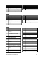
keyboard simultaneously. The keyboard mapping is
Bit
0
1
2
3
4
5
6
7
8
9
10
MC² keyboard key
"1"
"2"
"3"
"4"
"5"
"6"
"7"
"8
"9"
"0"
"↑"
Hex Code
0001
0002
0004
0008
0010
0020
0040
0080
0100
0200
0400
Binary Code
0000 0000 0000 0001
0000 0000 0000 0010
0000 0000 0000 0100
0000 0000 0000 1000
0000 0000 0001 0000
0000 0000 0010 0000
0000 0000 0100 0000
0000 0000 1000 0000
0000 0001 0000 0000
0000 0010 0000 0000
0000 0100 0000 0000
11
"←"
0800
0000 1000 0000 0000
12
"→"
1000
0001 0000 0000 0000
"↓"
2000
0010 0000 0000 0000
13
A-B SuperBridge Technical Reference
17
Bit
14
15
MC² keyboard key
"X"
"ENT"
Hex Code
4000
8000
Binary Code
0100 0000 0000 0000
1000 0000 0000 0000
Possible errors bits are 0 and 3. See Request Error Bits, N12:5,13,21.. (page 16)
Bit 5
(0020)
(x_RGETREG)
Request register contents. The numerical value of the register number must be
present in the MC Request Integer Parameter N13:5,12,19.. (page 18). Upon
completion, bit 5 of Request Done Bits, N12:4,12,20.. (page 16), will be set. If
no errors occurred, the content of (value in) the register will be present in
Request Float Result F14:6,14,22.. (page 19). Possible errors bits are 0 and 2.
See Request Error Bits, N12:5,13,21.. (page 16).
Note. An easier and more efficient method of getting the content of a MC
register is to tag it. See Fast Tag Register Number, N13:0,7,14.. (page 17) and
Slow Tag Register Number 1 - 3 N,13:1-3,8-10,15-17.. (page 17)
Bit 6
(0040)
(x_RPUTREG)
Update register contents. The numerical value of the register number to
update must be present in the MC Request Integer Parameter N13:5,12,19..
(page 18). The numerical value of new register content must be present in MC
Request Float Parameter, F15:1,4,7.. (page 19) Upon completion, bit 6 of the
Request Done Bits, N12:4,12,20.. (page 16), will be set. Possible errors bits
are 0 and 2. See Request Error Bits, N12:5,13,21.. (page 16)
Bit 7
(0080)
(x_RCLRLRM)
Clear all general alarms or warnings. This has the same effect as pressing the
‘Clear General Alarms’ button on the MC² or the ‘ACK ALL’ touchpad on the
MC³. The MC General alarm or warning output will go to OFF state, and the
MC general alarm or warning indicator will go off. Note that Fault indicators,
existing in the MC³ models 30.10.EX and 24.10.EX will not be cleared, using
this request bit.
Bit 8
(0100)
(x_RCLRSUB)
Clear the subtotal. This has the same effect as pressing the ‘Clear Subtotal’
button on the MC. Possible error bit is 2. See Request Error Bits, N12:5,13,21..
(page 16)
Bit 9
(0200)
(x_RDLSEC)
Download secondary (batch) setpoints. This bit will cause any value (including
zero) in Secondary SetPoint, F15:2,5,8..(x_SECPT) (page 19) to be
continuously downloaded as a secondary (batch) setpoint to the MC.
Bit 10..15
Reserved
MC Request Integer Parameter N13:5,12,19..(x_RINTPAR)
This integer is used to hold request parameters. See MC Control Word, N13:4,11,18.. (page 17).
External Inputs, N13:6,13,20..
Logical inputs in some MC³ controllers can be mapped to up to 16 external inputs. They appear
as bits in this word. External input 1 corresponds to bit 0 etc. This is useful when the PLC
controls the MC inputs directly.
Floating Point Report File, F14
SuperBridge will maintain a PLC type floating point file, with 8 floats per connected MC. The
purpose of this file is to make floating point data available to the PLC ladder or MMI programmer.
The file is read only. The file name is F14.
The following is a specification of the 8 floats belonging to a certain MC.
A-B SuperBridge Technical Reference
18
Fast tagged value, F14:0,8,16..(x_FTAGV)
This float contains the value of the register tagged in Fast Tag Register Number, N13:0,7,14..
(page 17). The value is updated in the fast loop.
Slow tagged values 1 - 3, F14:1-3,9-11,17-19..(x_STAG1V, x_STAG2v, x_STAG3V)
These float contains the values of the registers tagged in Slow Tag Register Number 1 - 3
N,13:1-3,8-10,15-17.. (page 17) The values are updated in the slow loop.
Process Value, F14:4,12,20..(x_PROCV)
The value in this float depends on the MC model. It is normally the feedrate. See Process Value
(page 24). The value is updated in the fast loop.
Total, F14:5,13,21..(x_TOTAL)
All MC applications support a totalizer. The current total is available in this float. The value is
updated in the fast loop.
Request Float Result F14:6,14,22..(x_FLTRES)
This float contains the value resulting from a request. See MC Control Word, N13:4,11,18.., page
17
Reserved, F14:7,15,23..
This float is reserved for future expansion.
Floating Point Control File, F15
SuperBridge will maintain another PLC type floating point file, with 3 floats per connected MC.
The purpose of this file is to make it possible for the PLC ladder or MMI programmer. The file is
read and write. The file name is F15.
The following is a specification of the three floats belonging to a certain MC.
SetPoint, F15:0,3,6..(x_SETPT)
The value in this float will be downloaded to the MC as the current setpoint, if bit 1 in the MC
Control Word, N13:4,11,18.., page 17 is set. See also Bit 8 of MC Status Word, N12:0,8,16..,
page 14
MC Request Float Parameter, F15:1,4,7..(x_FLTPAR)
The value in this float is used to hold request parameters. See MC Control Word, N13:4,11,18..,
page 17.
Secondary SetPoint, F15:2,5,8..(x_SECPT)
The value in this float will be downloaded to the MC as the current secondary setpoint, if bit 9 in
the MC Control Word, N13:4,11,18.., page 17 is set. See also Bit 10 of MC Status Word,
N12:0,8,16.., page 14 Only MC³ 24.96.EX.D or later or 30.20.EX.Beta or later supports
secondary (batch) setpoints.
A-B SuperBridge Technical Reference
19
UNSOLICITED MESSAGES SPECIFICATION
SB will act as a PLC when receiving unsolicited messages that request reading and writing data
to and from the four data files. Control files (N13 and F15) can be read from and written to.
Report file (N12 and F14) can only be read. Some PLC-2 unsolicited messages are also
supported for backwards compatibility. A-B DH+ and DH485 messages are specified in [6].
Issuing messages that are not supported by SB will generate an extended error return message
0xF00E.
PLC TYPED MESSAGES
These messages are typically generated by a PLC message rung, that is, in a PLC to PLC or
PLC to SB conversation, where the PLC solicits the message.
PLC Typed Read
See [6], page 3.6-11. With A-B terminology, this is command 0x0F, function 0x68. Data will be
returned if any element of N12, N13, F14 or F15 is requested, and the last element requested is
within the SB file range for the requested file. If other files are requested, extended error code
0xF006 is returned. If the last element requested is beyond the last element in the requested SB
file, extended error code 0xF00A is returned. If too many (more than 100 for N12 and N13, 50 for
F14 and F15) elements are requested, extended error code 0xF009 is returned.
PLC Typed Write
See [6], page 3.6-12. With A-B terminology, this is command 0x0F, function 0x67. Data will be
accepted to any N13 or F15 element if the last element requested is within the SB file range for
the requested file. If other files are requested, extended error code 0xF006 is returned. If the last
element requested is beyond the last element in the SB requested file, extended error code
0xF00A is returned. If too many (more than 100 for N13, 50 for F15) elements are requested,
extended error code 0xF009 is returned.
PLC WORD RANGE MESSAGES
These messages are typically generated by a MMI software packages, such as WinView and FIX
DMACS for Windows, that is, in a MMI to PLC or MMI to SB conversation, where the MMI solicits
the message.
PLC Word Range Read
See [6], page 3.6-15. With A-B terminology, this is command 0x0F, function 0x01. Data will be
returned if any element of N12, N13, F14 or F15 is requested, and the last element requested is
within the SB file range for the requested file. If other files are requested, extended error code
0xF006 is returned. If the last element requested is beyond the last element in the requested SB
file, extended error code 0xF00A is returned. If too many (more than 100 for N12 and N13, 50 for
F14 and F15) elements are requested, extended error code 0xF009 is returned.
PLC Word Range Write
See [6], page 3.6-16. With A-B terminology, this is command 0x0F, function 0x00. Data will be
accepted to any N13 or F15 element, if the last element requested is within the SB file range for
the requested file. If other files are requested, extended error code 0xF006 is returned. If the last
A-B SuperBridge Technical Reference
20
element requested is beyond the last element in the SB requested file, extended error code
0xF00A is returned. If too many (more than 100 for N13, 50 for F15) elements are requested,
extended error code 0xF009 is returned.
PLC Read-Modify-Write
See [6], page 3.6-5. With A-B terminology, this is command 0x0F, function 0x26. Data in N13
(only) will be modified if the last element requested to be modified is within the SB file range for
N13. If other files are requested, extended error code 0xF006 is returned. If the last element
requested is beyond the last element in N13, extended error code 0xF00A is returned.
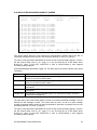
PLC-2 UNPROTECTED MESSAGES
A PLC-2 is, from a data message standpoint, a contiguous block of memory. One element of
memory is one byte long. Address notation is typically octal. The SB files are mapped into a
virtual PLC-2 memory with an associated start address, settable in SUPERB.INI, see
[PLC2DATA] Section, PLC2Base entry (page 45). The mapping order is N12, N13, F14, F15.
There are two bytes per element in N files, and four bytes per elements in F files. There are no
spaces between the files. Since the smallest element in SB are integers (two consecutive bytes),
requests to odd addresses are rejected.
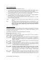
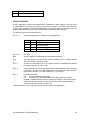
To calculate an PLC-2 address for a SB PLC-5 file element, use the following formulas, where A
is the PLC-2 address, O is the PLC2Base entry in SUPERB.INI (page 45), converted to a decimal
value, E is the element number and M is the Controllers entry in SUPERB.INI (page 41):
For N12:
For N13:
For F14:
For F15:
A
A
A
A
= O+E
= O + M⋅ 8 + E
= O + M ⋅ 15 + E ⋅ 2
= O + M ⋅ 31 + E ⋅ 2
Most MMI applications, as well as message rungs, take an octal value for the PLC-2 address, so
A normally has to be converted to octal.
PLC-2 did not support floating point numbers. Most MMIs do, however, so when data in F14 or
F15 is manipulated, measures has to be taken to re-create the floating point numbers properly in
the MMI. Floats are accepted or transmitted as IEEE 32 bit format (4 bytes), with the least
significant byte sent or accepted first. The IEEE 32 bit floating point format looks like this:
Bit:
Content:
31
S
30...
E7...
23
E0
22...
M1...
0
M23
S:
sign bit (1 = negative number, 0 = positive number)
E7-E0
8-bit exponent (bias 127)
M1-M23
23-bit mantissa with implied M0 = 1
In some instances, the word order for the floating point number has to be reversed, most notably
when using a message rung in a PLC-5. This can be done by setting the PLC2ReverseFloat
entry in the [PLC2DATA] Section (page 45) in SUPERB.INI to 1.
For older MMI system, that does not support floating point numbers, an alternate encoding is
available. The first of the two words contains the integer part of the number, maximized to 32767
and minimized to -32767. The second number contains the fractional part represented by an
positive integer, with an implied four decimal places. This encoding is enabled by setting the
PLC2ReverseFloat entry in the [PLC2DATA] Section (page 45) in SUPERB.INI to 2.
A-B SuperBridge Technical Reference
21
PLC-2 Unprotected Read
See [6], page 3.2-8. With A-B terminology, this is command 0x01. Data will be returned if the last
element requested is within the SB file range for F15, mapped into a PLC-2 memory image, as
described above. If other elements are requested, or the length in bytes of the requested data
table is greater than 244, error code 0x50 is returned. Note that it is possible to request data that
passes mapped PLC-5 file boundaries, i.e. the element following the last N13 element is F14:0.
PLC-2 Unprotected Write
See [6], page 3.2-9. With A-B terminology, this is command 0x08. The start element and the
number of elements must be entirely within the PLC-2 mapped image of N13 or F15 in order to
be accepted. If other elements are requested, or the length in bytes of the transmitted data table
is greater than 244, error code 0x50 is returned. It is not possible to write to N13 and F15 with
one message, since F14, which is read only, is mapped between the two.
ERROR CODES RETURNED
The following error codes are returned if there is a problem with an unsolicited message:
0xF006
“Address doesn’t point to something usable” (Not N12, N13 F14 or F15).
0xF009
“Data file is too large” (more than 100 N12 or N13 elements requested or more
than 50 F14 or F15 elements requested).
0xF00A
“Transaction size plus word address is too large” (Element beyond the last
element requested).
0xF00E
“Command cannot be executed” (message not supported by SB).
0x50
“Addressing problem or memory protect rungs” (PLC-2 addressing problem)
See also [6], pages 4.1-3..5
A-B SuperBridge Technical Reference
22
MODEL SPECIFIC INFORMATION
SuperBridge was released years after the MC² weighing controller. For some older versions of
the controller software applications, full support is not available. This chapter explains limitations
and application specific information that relates to specific MC² models.
SUPPORTED FUNCTIONS
The following table lists any limitations of SuperBridge operation in relation to different MC²
models and versions. Models not listed here are not supported at all.
MC² Models
20.00.K
22.00.B
30.00.D
10.00.HP.O,A,B
10.00.HP.C, D
11.00.HP.A
20.00.HP.O,A,B
20.00.HP.C
30.00.HP.O,A-D
35.00.HP.O,A
MC³ Models
20.00.EX.Beta O,A
20.10.O,A-F
20.20.EX.O,A
24.10.EX.Beta
24.10.EX.O,A-I
24.96.EX.O,A
24.96.EX.B-C
24.95.EX.D-G
30.00.EX.O-E
30.10.EX.Beta
30.10.X.O-E
30.20.EX.Beta
31.51.EX.Beta
35.00.EX.O,A-B
40.10.EX.O,A
External
I/O
Set
Points
Pacing
Req.
Reg
Update
register
Max
Baud
No
No
No
No
No
No
No
No
No
No
One
One
One
No
Note 3
Note 3
Note 4
One
One
One
Yes
Yes
Yes
No
No
No
Yes
Yes
Yes
Yes
Yes
Yes
Yes
No
Yes
Yes
Note 5
Yes
Yes
Yes
Yes
Yes
Yes
No
Yes
Yes
Note 5
Yes
Yes
Yes
9600
19200
9600
9600
19200
19200
9600
19200
19200
19200
Yes
Yes
Yes
Yes
Yes
No
Yes
Yes
Yes
Yes
Yes
Yes
Yes
Yes
Yes
One
One
Two
One
One
One
One
Two
One
One
One
Two
Note 3
Note 3
One
Yes
Yes
Yes
Yes
Yes
Yes
Yes
Yes
Yes
Yes
Yes
Yes
Yes
Yes
Yes
Yes
Yes
Yes
Yes
Yes
Yes
Yes
Yes
Yes
Yes
Yes
Yes
Yes
Yes
Yes
Yes
Yes
Yes
Yes
Yes
Yes
Yes
Yes
Yes
Yes
Yes
Yes
Yes
Yes
Yes
19200
19200
19200
19200
19200
19200
19200
19200
19200
19200
19200
19200
19200
19200
19200
Notes
Note 1
Note 2
Note 2
Note 2
Note 1:
An error in the 30.00.D application makes it impossible for SuperBridge to detect
the fact that the scale is rerated, calibrated or altered in the diagnostics menu.
Note 2:
This application should be updated to the latest version when used with
SuperBridge.
A-B SuperBridge Technical Reference
23
Note 3:
See Setpoint (page 24).
Note 4:
An error in the 20.00.HP.O, A and B applications makes it impossible for
SuperBridge to detect the fact that the controller is taken out of “Comm Setpoint
Mode”.
Note 5:
Some scaling problems exist for some registers. If bit 6 or 7 in the register
property word is set, unpredictable results can occur. See Useful Registers, page
29.
PROCESS VALUE
The process value is, with the following exceptions, the feedrate, as displayed in the root node or
main screen of the controller. The exceptions are:
11.00.HP
Current Gross Weight, with high resolution.
35.00.HP
Actual Batch Total for last batch weighed out.
SETPOINT
The setpoint value is, with the following exceptions, used as the feedrate setpoint, when the
controller is in “Comm Setpoint” or “Remote Serial” mode. The exceptions are:
10.00.HP
The setpoint value is transferred to the High Feedrate alarm limit.
11.00.HP
The setpoint value is transferred to the weight value for limit switch number 3.
35.00.HP
The setpoint value is used as the batch setpoint when the controller is in “Comm
Setpoint” mode.
Secondary setpoints, normally used for MCs that has a feedrate and a batch setpoint, are used
for the batch setpoint. The batch setpoint mode has to be “Remote Serial”. Currently, secondary
setpoint is only supported by MC³ 24.96.EX.D and 30.20.EX.Beta.
GENERAL ALARMS AND WARNINGS
The General Alarm bits are mapped out according to the following table. Detailed information
about the meaning of the alarms is available in the operations manual for the controllers.
Warnings mapped in all MC³ models except 24.96.EX depend on which inputs or outputs are
qualified for warning. The bit order can be found by displaying the warning screen in the
controller, when it has been configured
Controller
20.00.K
30.00.D
Bit
1
2
3
4
6
7
0
1
2
3
4
Meaning
Overflow
A/D Overrange
Auto-Tare Reject
Master Comm Lost
Display Failure
Display Failure
A/D Overrange
Hopper Empty
Slow Fill
Over Fill
Master Comm Lost
A-B SuperBridge Technical Reference
Controller
22.00
10.00.HP
Bit
6
7
4
6
7
1
2
3
4
5
6
Meaning
Display Failure
Display Failure
Master Comm Lost
Display Failure
Display Failure
A/D Overrange
Auto-Tare Reject
Master Comm Lost
A/D Underrange
Display Failure
Display Failure
24
Controller
11.00.HP
20.00.HP
30.00.HP
35.00.HP
Bit
7
8
1
2
3
4
5
7
8
9
1
2
3
4
5
6
7
8
1
2
3
4
5
6
7
8
9
11
14
1
2
3
4
5
Meaning
HPAD Not Set-Up
Test OverFlow
Scale Overload
Scale Underload
A/D Underrange
A/D Overrange
Bad Tare
HPAD Not Set
Bad Low Display
Comm Lost
A/D Overrange
Auto-Tare Reject
Master Comm Lost
A/D Underrange
Display Failure
Display Failure
HPAD Not Set-Up
Test OverFlow
Scale Overload
Scale Underload
A/D Underrange
A/D Overrange
Slow Fill
Hopper Empty
HPAD Not Set
Bad Low Display
Comm Lost
Overfill
No HPAD Data
Scale Overload
Scale Underload
A/D Underrange
A/D Overrange
Stable Timeout
Controller
24.96.EX
Bit
6
7
8
9
10
11
14
1
2
3
4
5
6
7
8
9
10
11
12
13
14
Meaning
Batch Timeout
HPAD Not Set
Bad Low Display
Comm Lost
Slow Fill
Fill When Batch
No HPAD Data
Belt Load Over
Limit
Belt Load Under
Limit
PCAD Near Zero
PCAD Near Full
Zero Tracking off
Limits
PCAD discrepancy,
load cells do not
agree
PCAD not setup
Tachos do not
comply
Comm Lost
Remote Setpoint
Out Of Range
No Speed Detected
Analog input out of
range.
MC³ Display Not
Responding
No Data from
PCAD
DIGITAL I/O
The Digital I/O bits are mapped out according to the following table. Detailed information is
available in the operations manual for the controllers. MC³ controllers are capable of mapping
logical inputs and outputs to physical I/O points. The actual mapping must be examined using the
‘Digital Inputs’ and ‘Digital Outputs’ mapping screens on the controller.
Controller
20.00.K
I/O
O
Bit
0
Meaning
High Alarm
A-B SuperBridge Technical Reference
Controller
I/O
O
Bit
1
Meaning
Low Alarm
25
Controller
30.00.D
22.00
10.00.HP
11.00.HP
20.00.HP
I/O
O
O
O
I
I
Bit
2
4
6
8
9
O
O
O
O
O
O
O
I
I
0
1
2
3
4
5
6
8
9
I
O
O
O
O
I
I
10
0
1
4
6
8
9
O
O
O
O
O
O
O
O
O
O
O
O
I
I
I
I
O
O
O
O
0
1
2
4
6
0
1
2
3
4
5
6
8
9
10
11
0
1
2
4
Meaning
Low Speed Cut off
In Control
General Alarm
Soft Start
Control Master
Reset
High Alarm
Low Alarm
Filling
Slow Fill
In Control
Feeder Running
General Alarm
Soft Start
Control Master
Reset
Remote Fill
High Alarm
Low Alarm
In Control
General Alarm
Soft Start
Control Master
Reset
High Alarm
Low Alarm
Low Speed Cut off
Calibration
General Alarm
In Center Zero
Scale Stable
Print Complete
Limit Switch 1
Limit Switch 2
Limit Switch 3
General Alarm
Print String A
Print String B
Clear Sub-Total
Tare
High Alarm
Low Alarm
Low Speed Cut off
In Control
A-B SuperBridge Technical Reference
Controller
I/O
O
I
I
Bit
6
8
9
30.00.HP
O
O
O
O
O
O
O
I
I
0
1
2
3
4
5
6
8
9
I
O
O
O
O
10
0
1
2
3
O
O
O
I
I
I
O
O
O
O
O
O
O
O
I
I
I
I
I
I
I
I
4
5
6
8
9
10
0
1
2
3
4
5
6
7
8
9
10
11
12
13
14
15
35.00.HP
MC³
Meaning
General Alarm
Soft Start
Control Master
Reset
High Alarm
Low Alarm
Filling
Slow Fill
In Control
Feeder Running
General Alarm
Soft Start
Control Master
Reset
Remote Fill
Fast Feed
Fine Feed
Fill valve open
Batch Out Of
Tolerance
Ready For Start
Batch Complete
General Alarm
Remote Print
Start Batch
Stop / Reset Batch
Rack 1 Output 1
Rack 1 Output 2
Rack 1 Output 3
Rack 1 Output 4
Rack 1 Output 5
Rack 1 Output 6
Rack 1 Output 7
Rack 1 Output 8
Rack 1 Input 1
Rack 1 Input 2
Rack 1 Input 3
Rack 1 Input 4
Rack 2 Input 1
Rack 2 Input 2
Rack 2 Input 3
Rack 2 Input 4
26
Note that the status of unused digital inputs in MCs are reported to the MC Digital I/O,
N12:2,10,18.. (page 15), even if they are not used by he MC application. They can be used as
remote inputs for the ladder logic.
INTERNAL STATE
Some cyclic controller applications have an internal state variable, useful for indication of what’s
going on in. The state variable is numerical, and can not be used for bit monitoring.
30.00.HP
State
0
1
2
3
4
5
6
7
Meaning
Check for fill requirement at startup
Prepare for normal feed
Wait for filter values to stabilize
Norma LIW feed
Prepare for a fill cycle
Filling
Ceck for auto-fill condition
Preparations after fill cycle
State
8
9
10
11
12
12
Meaning
Stabilization time after filling
Prepare for normal feed after filling
Prepare for cleanout cycle
Run cleanout cycle to low weight
Run Cleanout cycle (time) after low
weight
Waiting for fill after cleanout complete
35.00.HP
State
0
1
2
3
4
Meaning
Test for autofill
Stopped by button 7, "STOP BATCH"
Ready for start of new batch
Preparing for a batch
Prepare for mandatory wait before
stable
Wait before stable, before batching
Stable check before batching
Check if fast feed needed
Start fast feed
Fast feeding
Check if skip fine feed
Start fine feed
Fine feeding
Init wait after feed
State
14
15
16
17
18
19
20
21
22
23
24
Meaning
Wait before stable after batching
Wait for stable after batching
Calc weight batched out so far
Calculate new preact
Prepare for filling
Arm timer before filling
Wait before fill
Wait for stability for filling
Start filling
Filling, check for overfill, done
Stop filling
State
Meaning
State
Meaning
0
Prepare for normal feed
1
Wait for filter values to stabilize
5
6
7
8
9
10
11
12
13
30.00.EX
A-B SuperBridge Technical Reference
27
State
Meaning
2
3
4
5
6
Normal LIW feed
Filling
Stabilization time after filling
Run cleanout cycle to low weight
Run Cleanout cycle (time) after low
State
7
8
Meaning
weight
Feeder Stopped
A Blocking condition occurred
31.51.EX
State
Meaning
State
Meaning
0
1
2
3
4
5
Waiting for next Batch
Preparing for a batch
Wait to become stable
Zero scale
Fill bucket
Wait to become stable and check
weight
Open batch gate
7
8
9
10
11
12
Wait to empty
Close Batch Gate
Aborted Batch
A Blocking Condition occured
A Fault Occurred
Restart batching
6
35.00.EX
State
0
Meaning
Test for autofill
1
Stopped
BATCH"
2
ready for start of new batch,waiting
for "START BATCH" or LOIN)
3
Batchout starts here
4
Prep for mandatory wait before
stable, before batching
by
button
7,
"STOP
State
13
Meaning
Arm timer for mandatory wait
14
Wait before stable after batching
15
Wait for stable after batching
16
Calc weight batched out so far
17
Calculate new preact
18
Prepare for filling
19
Arm timer before filling
5
Wait before stable, before batching
20
Wait before fill
6
Stable check before batching
21
Wait for stability for filling
7
Check if coase feeding or skip to
finefeed
22
start filling
23
Filling, check for overfill, done
8
Start coarse feed
24
Stop filling
9
Coarse feeding, check for empty,
coarse done, pause, net increasing
25
Initialize for Cleanout
10
Check if skip fine feed, anr set dirty
= NO
26
Run cleanout
27
Run cleanout for empty time
11
Start fine feed
28
hopper weight past empty weight
12
Fine feeding, check for empty, fine
done, pause, increasing net
29
check for rerun or return
A-B SuperBridge Technical Reference
28
State
30
Meaning
Clearing the current Batch
USEFUL REGISTERS
All MC² applications contains a numbered table of parameters, called registers. They are useful
in a SuperBridge environment for monitoring and control purposes. In the following sections, the
content of the registers for the different applications are listed, along with the property word. The
property word describes access rules, decimal places and scaling of the registers.
The property word has the following layout:
Bit 15..14
Internal storage format, according to the following table:
Bit 15
0
0
1
1
Bit 14
0
1
0
1
Storage format
long (32 bit integer)
char (8 bit integer)
int (16 bit integer)
float (32 bit IEEE floating point)
Bit 13..10
Not used
Bit 9
Set if the register is initialized to zero at controller cold start.
Bit 8
Set if the register is included in the register checksum, that is, is safely retained
when the controller is powered down.
Bit 7..6
At least one of the bits are set if the register is scaled. SuperBrigde will unscale
the register and convert it into a float.
Bit 5..4
Access mask. 00: Read and write permitted. 01: Read permitted. Write permitted
if dip switch 1 is open on the MC² display board, or the ‘Extended Access’ logical
input is ON in the MC³. 10: Read access only. 11: No access.
Bit 3..0
Decimal place codes.
0..4:
0..4 decimal places, respectively.
5..9
according to the values in registers 005..009, respectively, with the
exception of models 20.00.K and 22.00, where the number of decimal places for
code 009 is found in register 170, and 30.00.D, where the number of decimal
places for code 009 is found in register 134.
Contact Merrick for a list of registers used by the controllers in your application.
A-B SuperBridge Technical Reference
29
DIAGNOSTIC SCREENS
If a VGA compatible monitor and a PC keyboard is connected to the SB host PC, several
diagnostic screens are available. They are usable for verification, troubleshooting, checking
ladder and MMI programming, and for editing data in N13 and F15. Note that with the exception
of the Home Screen, there is a SB performance penalty associated with the diagnostic display.
For all screens in this section, the following SUPERB.INI was used:
;
;
SUPERB.INI
09-29-95/LTM Manual Example Setup
[SIZES]
;
Only one port supported
ComPorts = 1
Controllers = 5
Segments = 6
[IRQ]
;
Settings for COM1
PortVector = 0C
PIDMask = 10
[PORT0]
;
COM1, 19200 Baud
UartBase = 3F8
DlabReg = 0006
[PLCDEFAULT]
DefaultStation = 60
[PLC2DATA]
PLC2ReverseFloat = 1;
[SEGMENT4]
SourceAddress = N12:16
DestAddress = N12:0
Elements = 24
Station = 1
Access = MODIFY
Processor = SLC500
[SEGMENT5]
SourceAddress = F14:16
DestAddress = F14:0
Elements = 24
Station = 1
DataTypes = RAW
Access = MODIFY
Processor = SLC500
•
COM1 is used for communications, instead of COM2, which is default.
•
There are five MCs in this system; one of them, MC Index 3, is set off-line.
•
SB reports to and is being controlled by a PLC-5, station number 60. In this PLC, bit
N13:25/0 is set, taking controller index 3 offline. See MC Control Word, N13:4,11,18.. (page
17).
•
Data in the report files N12 and F14 for the last three controllers are also reported to a SLC500/04 with station number 1.
•
A WinView MMI with station number 41 is constantly interrogating SB for floating point data
for the first four MCs, maintaining a graph.
•
Some message rungs exist in the PLC-5, station number 60, one of which causes an error
return.
A-B SuperBridge Technical Reference
30
THE HOME SCREEN
1
2
3
4
5
6
7
8
9
10
11
12
13
14
15
16
17
18
19
20
21
22
23
24
25
SuperBridge Home Screen
Merrick - Allen-Bradley SuperBridge
Copyright (C) 1996 Merrick Industries
All Rights Reserved
Ver 0.99 Built May 13 1998, 16:15:52
0: Run/30.00.HP.A
4: Run/11.00.HP.A
0: Run/N12:0
4: Run/N12:16
F2
MC Data
Time:
Started:
MCs:
Segments:
Thu May 14 14:08:26 1998
Thu Ma4 14 14:05:24 1998
5
6
MC Status map
Run/20.00.HP.C
Run/30.00.HP.A
A-B Segments map
Run/N13:0
Run/F14:0
Run/F14:16
F3
A-B Msgs
Ofl/Unknown
Run/F15:0
F10
Exit
This screen show overview status for SB. It is also the default and preferred screen during
normal operations, since the SB performance penalty is minimal.
Displayed information:
Line
3..6
Left
3
4
5
6
8f
Keyword
Explanation
Revision, copyright and build data for the SB software application.
Time:
Started:
MCs:
Segments:
MC Status
map
11f
A-B Segments
map
Current time in the SB host PC.
The time in SB host PC at which SB was booted.
Number of configured MCs.
Number of configured A-B file copy segments.
Communication status and application models/versions for all configured
MCs. Possible status are Run (running, no communication problems),
Ofl (taken off-line), Not Used, Rev (communications reviving attempt in
progress) and Err (Communication problems). Four MCs are shown per
screen line.
Communication status and first source element for all configured A-B
File Copy segments. Possible status are Run (running, no
communication problems) and Err (Communication problems). Four
segments are shown per screen line.
Function keys:
F2
Switch to MC Data Screen (page 32)
F3
Switch to A-B Unsolicited Messages Diagnostic Screen (page 39)
F10
Stop SB and return to the DOS prompt
A-B SuperBridge Technical Reference
31
MC DATA SCREEN
1
2
3
4
5
6
7
8
9
10
11
12
13
14
15
16
17
18
19
20
21
22
23
24
25
MC Data, Controller Index 2
Number of MCs configured
MC in use (1 = YES, 0 = NO)
MC WatchDog (0.1 s ticks)
MC Revive Time (ms)
MC Controller Number
5
1
200
20000
3
Comm Errors logged
Fatal Comm Errors
State Machine Index
MC Model/Version
MC Current Status
WI Elems N12:016 Stat MCSt DI/O LRMS RDON RERR RRES XOUT
Pending:
0120 0003 0730 0000 0000 0000 0000 0000
Completed:
0120 0003 0730 0000 0000 0000 0000 0000
RI Elems N13:014 FTag Stg1 Stg2 Stg3 MCCT RINT EXIN
Pending:
002C 0090 0093 00D9 0002 00CD 0000
Completed:
0000 0000 0000 0000 0000 0000 0000
Edit Ints (hex): [
][
][
][
][
][
][
]
WF Elems F14:016
FTag
Stg1
Stg2
Pending:
7.863
0.000
15.000
WF Elems F14:020
ProcessVal
Total
ReqFResult
Pending:
10.500
885.600
0.000
RF Elems F15:006
SetPoint
ReqFParam Sec SetPoint
Pending:
6.395
7000.000
0.000
Edit Floats:
[
][
][
]
F1
Home Screen
F2
MC Diags
F3
A-B Msgs
0
0
19
30.00.HP.A
Running
Stg3
2.180
RSRV
0.000
F6
F7
Next MC Prev MC
F10
Exit
The MC Data Screen shows status information and current A-B file data for one MC. It is also
possible to edit the local SB content of the two control files N13 and F15. If A-B file copy is
enabled for these files, editing is meaningless, since the edited data item will be overwritten by
the next A-B file read.
Line
1
3
4
5
6
7
3
4
5
6
Keyword
Number of
MCs
configured
In Use
MC
WatchDog:
MC Revive
Time
MC Controller
Number
Comm Errors
logged
Fatal Comm
Errors
State Machine
index
MC
Model/Version
Explanation
MC Controller index for data currently displayed
Number of configured MCs.
A 0 indicates the data for the MC is allocated, but never used. There is
normally no controller at all with this index.
The value of the local MC watchdog timer in 0.1 s. See WatchDog (page
42)
How often (in ms) SB will attempt to re-establish communication with a
MC that has had a fatal (non-recoverable) communication error. See
ReviveTime (page 42)
The local MC controller Number setting. See MC Communication
Parameters (page 10) and ControllerNumber (page 41)
How many recoverable (non-fatal) communication errors that have
occurred for this MC since SB was started.
How many fatal (non-recoverable) communication errors that have
occurred for this MC since SB was started.
Used for telephone support. This value rapidly scans through a
seemingly random number of values.
MC application program model and version. “Unknown” if the no
successful communication has taken place with the MC or if the model
A-B SuperBridge Technical Reference
32
Line
Keyword
7
MC Current
Status
9-11
IR Elems
1215
IC Elems
1619
1215
FR Elems
FC Elems
Explanation
and version is unknown to SB (not supported)
Possible status are Running (running, no communication problems),
OffLine (taken off-line), NotUsed, Reviving (communications reviving
attempt in progress) and CommErr (Communication problems).
Integer Report data from N12. Integer Report File, N12 (page 14).
Hexadecimal representation. “Pending” means actual current data in SB.
Completed means the last data successfully copied to a PLC.
Integer Control data from N13. See Integer Control File, N13 (page 16).
Hexadecimal representation. “Pending” means actual current data in SB.
Completed means that the action required by the data has been initiated.
It is possible to edit N13, using tab/backtab to move the cursor to the
field to edit, enter digits (Hex) and hit return.
Floating Point Report data from F14. See Floating Point Report File, F14
(page 18). “Pending” means actual current data in SB.
Floating Point Control data from F15. See Floating Point Control File,
F15 (page 19). “Pending” means actual current data in SB. It is possible
to edit F15, using tab/backtab to move the cursor to the field to edit,
enter digits (including minus sign and decimal point) and hit return.
Function keys:
F1
Switch to The Home Screen (page 31)
F2
Switch to MC Combined Diagnostic Screen (page 34)
F3
Switch to A-B Unsolicited Messages Diagnostic Screen (page 39)
F6
Switch to the MC with the next controller index
F7
Switch to the MC with the previous controller index
F10
Stop SB and return to the DOS prompt
A-B SuperBridge Technical Reference
33
MC Combined Diagnostic Screen
1
2
3
4
5
6
7
8
9
10
11
12
13
14
15
16
17
18
19
20
21
22
23
24
25
MC Combined Diagnostic Port 0 Controller Index 0
RxPtr:
0
TxPtr:
6
Used
ParErrs
Timeouts
BadataErrs
ErrErrs
MaxRetries
RxData: 30000000000000000006d
TxData: 2d6a
1¦State
3¦LastErr
0¦OvrErrs
1¦FrameErrs
6¦CsumErrs
0¦BusyErrs
0¦FormatErrs
0¦RFrmErrs
0¦CurrSlave
1¦CurrTelegram
2¦PortIndex
0¦ActiveMC
0¦FatalErrs
0¦BreakErrs
0¦AccessErrs
0¦RLimErrs
7¦TimerTicks
1¦UART IIR
1¦LastFatErr
0¦BufOverrs
0¦BadFncErrs
0¦NotSupErrs
0¦RetryCount
1¦UART LSR
-7
0
0
0
0
0
Used
1¦State
0¦TgmState
26¦SlowState
29¦TagIndex
1
LastAck
0¦AccessNakOK
0¦Rescaled
0¦TimeOut
6¦WatchDog
200
IdNum
38¦VerNum
67¦ModelIdx
17¦Pacing
0¦RegProp
0000
RegNum
150¦Port
0¦StartChar
A¦EndChar
D¦ControllerNr 1
Errors
3¦LastErr
-7¦FatalErrs
0¦LastFatalErr 0¦DownTime
0
RevTime
20¦InPuts
0003¦OutPuts
0078¦Alarms
0260¦NumRegs
313
RQRobin
3¦SetDlsa
1¦SetDlsc
1¦LastSp
6.395¦KeyLocked
0
Decimal Points 2 2 3 0 0
¦RegValue
3¦Scalef
21885
Total
1119.3000¦ProcV
994.0000¦
Bezel [
994] [Feedrate g/min ] Yled:40 Gled:FD
F1
Home Screen
F2
A-B Copy
F3
MC Data
F4
Next Port
F5
Prev Port
F6
F7
Next MC Prev MC
F10
Exit
This screen shows communications related data for one communications port (Serial port in the
SB host PC) and for one MC. The upper part of the screen shows port data, the lower MC data.
The port index is related to the serial port 0..3. It is mostly used by Merrick for telephone support
and for SB internal trouble-shooting. Some entries are useful for general trouble-shooting. They
are listed here:
Line
5
5
Keyword
Used
Last Err
5
FatalErrs
5
LastFatErr
6-8
10
ActiveMC
12
Used
12
State
12
TgmState
13
WatchDog
14
IDNum
14
VerNum
Explanation
A 0 indicates the data for the port is allocated, but never used.
Last communication error encountered on this port. See Numerical Error
Values (page 36)
How many fatal (non-recoverable) communication errors that have
occurred for this port since SB was started.
Last fatal (non-recoverable) communication errors encountered on this
port. See Numerical Error Values (page 36)
Individual statistics for each possible communication error on the port.
See Numerical Error Values (page 36)
There is at least one MC on this port that is active, that is, not Offline or
Not Used.
A 0 indicates the data for the MC is allocated, but never used. There is
normally no controller at all with this index.
Communication status. The numerical value of “MC Current Status” in
MC Data Screen (page 32)
Used for telephone support. This value rapidly scans through a
seemingly random number of values. See also MC Data Screen (page
32)
The value of the local MC watchdog timer in 0.1 s. See WatchDog (page
42)
The numerical value of the application model. Displayed if retrieved,
even if the specific application is not supported by SB.
The numerical value of the application version. Displayed if retrieved,
A-B SuperBridge Technical Reference
34
Line
Keyword
14
ModelIdx
14
Pacing
15
UnitAddress
16
Errors
16
LastErr
16
FatalErrs
16
LastFatalErr
16
DownTime
17
RevTime
17
InPuts
17
OutPuts
17
Alarms
17
NumRegs
18
18
18
18
19
20
20
SetDlsa
SetDlsc
LastSp
Leylocked
DecimalPoints
Total
ProcV
21
Bezel
21
YLed
21
GLed
Explanation
even if the specific version is not supported by SB.
A 0 here indicates that there is no support for this application/version
combination.
The controller is in pace mode. See also Bit 6 in MC Status Word,
N12:0,8,16.. (page 14).
The local MC controller Number setting in ASCII format. Subtract 48 to
get the Controller Number. See MC Communication Parameters (page
10) and ControllerNumber (page 42)
How many recoverable (non-fatal) communication error that have
occurred for this MC since SB was started. Same as “Comm Errors
logged” in MC Data Screen (page 32)
Last communication error encountered on this MC. See Numerical Error
Values (page 36)
How many fatal (non-recoverable) communication errors that have
occurred for this port since SB was started.
Last fatal (non-recoverable) communication errors encountered on this
MC. See Numerical Error Values (page 36)
How many ms this MC has waited for revival attempt after a fatal
communication error.
How often (in ms) SB will attempt to re-establish communication with a
MC that has had a fatal (non-recoverable) communication error. See
ReviveTime (page 42)
Hexadecimal representation of the MC physical inputs. See Digital I/O
(page 25)
Hexadecimal representation of the MC physical outputs. See Digital I/O
(page 25)
Hexadecimal representation of the MC Alarm bits. See General Alarms
(page 24)
The highest possible register number in this MCs model/version. See
Useful Registers (page 29)
Number of attempts to download a setpoint to an MC
Number of successful downloads of a setpoint to an MC
Value of the last downloaded setpoint to the MC
1 if keyboard/touchpad is locked, else 0
Current values of the five MC decimal point settings.
Current value of the MC Total. See Total, F14:5,13,21.. (page 19)
Current value of the MC Process Value. See Process Value,
F14:4,12,20.. (page 19)
For a MC², First field is a copy of what is displayed in the upper (seven
segment) display. Second field is a copy of what is displayed in the lower
(alphanumeric) display.
Hexadecimal representation of the state of the yellow LEDs in the MC²
front panel.
Hexadecimal representation of the state of the green LEDs and square
red light in the MC² front panel.
Function keys:
A-B SuperBridge Technical Reference
35
F1
Switch to The Home Screen (page 31)
F2
Switch to A-B File Copy Diagnostic Screen (page 37)
F3
Switch to MC Data Screen (page 32)
F4
Switch to port data for the next serial port
F4
Switch to port data for the previous serial port
F6
Switch to the MC with the next controller index
F7
Switch to the MC with the previous controller index
F10
Stop SB and return to the DOS prompt
Numerical Error Values
This is a list of the numerical values that can appear in a communication error field:
Value
2
4
8
16
-1
-2
-3
Name
OvrErr
ParErr
FrameErrs
BreakErr
FormatErr
BusyErr
AccessErr
-4
BadataErr
-6
-5
-7
-11
-12
-13
BadFncErr
PowUp
TimeOuts
RFrmErr
RLimErr
NotSupErr
Explanation
Serial communications Overrun error
Serial communications parity error
Serial communications framing error
Serial communications break condition detected
The MC detected an telegram with a bad format
The MC can’t perform the service requested in the telegram at this time
The MC can’t perform the service requested in the telegram because of
access restrictions
The MC can’t perform the service requested in the telegram because
parameter(s) are out of the legal limit
The requested function is unknown by this MC
The controller has been rebooted and needs comm re-initialization
SB timed out waiting for a MC response
Bad format in MC return telegram
Parameter(s) in MC return telegram are out of the legal limit
The MC Model/Version combination is not supported by SB.
A-B SuperBridge Technical Reference
36
A-B FILE COPY DIAGNOSTIC SCREEN
1
2
3
4
5
6
7
8
9
10
11
12
13
14
15
16
17
18
19
20
21
22
23
24
25
A-B File Copy Diagnostics
ErrCall:
ErrMsg:
Events
ExitFlag
DTL_I_SUCCESS, Operation Successful
1|Wtrs
922|LastState
66|LastError
0|WMask 00000002|RMask 00000000|MaskBits
Seg SrcAddr DesAddr El DType Access
0
N12:0
N12:0 40 WORD MODIFY
1
N13:0
N13:0 35 WORD
READ
2
F14:0
F14:0 40 FLOAT MODIFY
3
F15:0
F15:0 15 FLOAT
READ
4 N12:16
N12:0 24 WORD MODIFY
5 F14:16
F14:0 24
RAW MODIFY
F1
Home Screen
F2
A-B Msgs
F3
MC Diags
0|Status
0|
18
St Proc
IoS Attempt Rejects LastBad Time
60
PLC5
0
8
0
0
60
60
PLC5
0
38
0
0
60
60
PLC5
0
34
0
0
60
60
PLC5
0
38
0
0
50
1 SLC500
0
5
0
0
0
1 SLC500
0
32
0
0
60
F4
Next Page
F5
Prev Page
F10
Exit
This screen shows status for some central A-B communication registers and for each segment
defined for A-B file copy. See SB Configuration for File Copy (page 12) The ErrCall field in line 3
gives a textual representation of the last error encountered while attempting to communicate over
the DH+ network. Parameters in the segment list are:
Parameter
Seg
SrcAddr
DesAddr
El
DType
Access
St
Proc
IoS
Attempt
Explanation
Segment number. “N” in [SegmentN] Section (page 44)
A-B data file source address. The first element in the SB PLC-5 file involved in file
copy. See SourceAddress (page 44). This address must be an element of N12,
N13, F14 or F15.
A-B data file destination address. The first element in the target PLC-5 file involved
in file copy. The file type (N or F) must match the file type in “SrcAddr” above. See
DestAddress (page 44)
Number of elements in the segment. Must be less than 100 for an N file and less
than 50 for an F file. See Elements (page 45)
Data type for the file transfer. DataTypes (page 45). Note that for floating point files
copied to or from a SLC-500/04, the Data Type must be “RAW”.
See Access (page 45) must be “MODIFY”, for copy to the PLC, or “READ” for copy
from the PLC.
Station number for the target PLC, octal representation. See
Station (page 45)
Processor type for the target PLC. Legal values are PLC5 or SLC500. See
Processor (page 45)
Current I/O Status for the copy transaction. Should be either 1, indication transfer
in progress, or 0, indicating success. Other values indicate error conditions. The
ErrCall field in line 3 gives more information of the nature of the error.
How many file transfer attempts that has been made since SB was started.
A-B SuperBridge Technical Reference
37
Parameter
Explanation
Rejects
How many file transfer attempts that has been rejected since SB was started.
LastBad
I/O status for the latest rejected file transfer attempt.
Time
Transfer time in ms for the last file transfer
Function keys:
F1
Switch to The Home Screen (page 31)
F2
Switch to A-B Unsolicited Messages Diagnostic Screen (page 39)
F3
Switch to MC Combined Diagnostic Screen (page 34)
F4
Switch to next page of segment information. No effect if all segment lines fit on
one page.
F5
Switch to previous page of segment information. No effect if all segment lines fit
on one page.
F10
Stop SB and return to the DOS prompt
A-B SuperBridge Technical Reference
38
A-B UNSOLICITED MESSAGES DIAGNOSTIC SCREEN
1
2
3
4
5
6
7
8
9
10
11
12
13
14
15
16
17
18
19
20
21
22
23
24
25
A-B Unsolicited Messages Diagnostics
Telegrams
ExitFlag
Stn
Stn
Stn
Stn
Stn
Stn
Stn
Stn
Stn
Stn
Stn
Stn
Stn
Stn
Stn
Stn
041.
041.
041.
041.
041.
041.
041.
041.
041.
060.
041.
060.
041.
060.
041.
041.
Off|ErrorMsgs
0|WMask
PLC-5
PLC-5
PLC-5
PLC-5
PLC-5
PLC-5
PLC-5
PLC-5
PLC-5
PLC-5
PLC-5
PLC-5
PLC-5
Len =
PLC-5
PLC-5
F1
Home Screen
On|Unsols
2|RMask
Range Read F14:0,
Range Read F14:0,
Range Read F14:0,
Range Read F14:0,
Range Read F14:0,
Range Read F14:0,
Range Read F14:0,
Range Read F14:0,
Range Read F14:0,
Typed Read N12:0,
Range Read F14:0,
Typed Write N13:0,
Range Read F14:0,
54, Ret = 0050 {08
Range Read F14:0,
Range Read F14:0,
F2
MC Data
F3
A-B Copy
29
29
29
29
29
29
29
29
29
24
29
21
29
00
29
29
200|BadUnsols
0|MaskBits
1|LastRetCode
0|
0
elements
elements
elements
elements
elements
elements
elements
elements
elements
elements
elements
elements
elements
41 07 F8 01 A0 41 00 00 A0 41 7B 14 A0 }
elements
elements
F4
Stop Tgm
F5
Start Tgm
F6
F7
F10
Stop Er Start Er Exit
This screen shows status for some central A-B communication registers and for the last 16
unsolicited messaged received by SB. See Secondary SetPoint, F15:2,5,8..(x_SECPT)
The value in this float will be downloaded to the MC as the current secondary setpoint, if bit 9 in
the MC Control Word, N13:4,11,18.., page 17 is set. See also Bit 10 of MC Status Word,
N12:0,8,16.., page 14 Only MC³ 24.96.EX.D or later or 30.20.EX.Beta or later supports
secondary (batch) setpoints.
Unsolicited Messages Specification (page 19). The upper part of the screen contains some status
information:
Parameter
Telegrams
ErrorMsgs
Unsols
BadUnsols
LastRetCode
Explanation
“Off” or “On” Indicates if good messages are logged to the lower part of the
screen or not. See F4 and F5 below.
“Off” or “On” Indicates if invalid messages are logged to the lower part of the
screen or not. See F6 and F7 below.
How many good unsolicited messages that have been processed by SB since it
was started.
How many invalid unsolicited messages that have been processed by SB since it
was started.
The last return code generated by SB for an unsolicited message. See Error
Codes Returned (page 22)
The lower part of the screen shows data for the last 16 received unsolicited messages. The row
beneath the last message in blank. The screen does not scroll. A row for a good message
contains requesting station number in octal representation, what kind of message received, see
Secondary SetPoint, F15:2,5,8..(x_SECPT)
The value in this float will be downloaded to the MC as the current secondary setpoint, if bit 9 in
the MC Control Word, N13:4,11,18.., page 17 is set. See also Bit 10 of MC Status Word,
N12:0,8,16.., page 14 Only MC³ 24.96.EX.D or later or 30.20.EX.Beta or later supports
secondary (batch) setpoints.
A-B SuperBridge Technical Reference
39
Unsolicited Messages Specification (page 19), which A-B data file was requested and the
number of elements. A row for a bad message contains requesting station number in octal
representation, the length (in bytes) of the message, the error return code issued, see Error
Codes Returned (page 22), and the message body itself, starting with the A-B command in hex.
In this example (Row 20), function 0x08 was requested (PLC-2 unprotected write), the address
requested was 01F8 (hex bytes), corresponding to word address 374 (Octal), indicating an offset
of 248 (decimal bytes) in the SB PLC-2 virtual memory map, since the PLC-2 base address in
this example is set to 200 (octal). Using the information in PLC-2 Unprotected Messages (page
21) to convert the PLC-2 address to a PLC-5 file element, this would be F14:24, which is a readonly file, that can not be written to.
Function keys:
F1
Switch to The Home Screen (page 31)
F2
Switch to MC Data Screen (page 32)
F3
Switch to A-B File Copy Diagnostic Screen (page 37)
F4
Stop logging good messages
F5
Start logging good messages
F6
Stop logging error messages
F7
Start logging error messages
F10
Stop SB and return to the DOS prompt
A-B SuperBridge Technical Reference
40
CONFIGURATION
SB is completely configurable via the configuration file, SUPERB.INI. The file can be edited using
a text editor. It is loaded every time the SB application is started up. The file is divided into
sections with a format similar to Windows initializations files.
[SIZES] SECTION
The sizes section deals with the size of the SB application, such as number of connected MCs.
ComPorts
Depending on how many MCs are connected, one or more RS-422 serial ports are used for the
MC connections. If more than one port is used, a multiport adapter is installed in the SB host PC.
This entry specifies the number of ports used. Default is 1.
Controllers
This entry specifies the number of connected MCs. Default is 5.
Segments
If automatic file transfers is desired, this entry must have a non-zero value. It describes how
many file transfer segments that are to be active. In the default case of five MCs or less, this
value is normally four, since four different files are involved: N12, N13, F14 and F15. If more than
five MCs are connected each individual file must be divided up in segments, normally one
segment per five MCs. Default is calculated as
[
]
Segments = 4 ⋅ INT (Controllers + 4) / 5 ,
where INT is the integer part of the argument. See also SB Configuration for File Copy (page 12).
Default is 0, that is, no file transfer is enabled.
[IRQ] SECTION
This section deals with hardware and interrupt properties of the serial ports used for MC
communications. The ports are assumed to share one interrupt.
PortVector
This is the interrupt vector number for the port in hex. Use 0B for COM2 (default) or 0C for
COM1.
PIDMask
This is the mask word used for the Priority Interrupt Decoder interrupt request mask bit. Use 08
for COM2 (default) and 10 for COM1.
[PORTN] SECTIONS
SB communicates with MCs using a single COM port (COM 1..4) or using a multiport adapter.
The multiport adapter can have up to four serial ports, on different I/O addresses, and must share
a common IRQ line. This section specifies properties for the communication ports used for each
port. N can be 0, 1, 2 or 3, but must be less than the ComPorts entry in the [Sizes] Section, page
41.
A-B SuperBridge Technical Reference
41
UartBase
Base address for the UART, port N, hexadecimal. Default is 2F8 for section [Port0], which is the
base address for COM2 in a normal PC. COM1 has normally base address 3F8. Sections
[Port1]..[Port3] does not have a default; the base address for those ports have to be specified
when a multiport adapter is used.
DLABReg
This entry indirectly specifies the baud rate used for each port. It is possible to run different ports
with different baud rates. Old MC² applications supports baud rates up to 9,600, newer up to
19,200, and MC³ can communicate up to 38,400 baud. The entry is in hexadecimal format.
Default is 06 for 19,200 baud. Use the following table:
Baud Rate
DLABReg value
4,800
9,600
19,200
38,400
0018
000C
0006
0003
Retries
This is the number of times SB will try to recover from a MC communication error. Default is 2.
Increase this number if the communication lines are very long and noise is present. There is a
performance penalty associated with high values.
[MCN] SECTIONS
These sections define properties associated with a particular MC. N is the controller index, which
start at 0 and end at Controllers (page 41) minus one.
Used
Valid entries are 0 and 1. 1 is default. A 0 means the controller with index N is never to be used.
This is useful when data must be allocated for a growing number of controllers, and the A-B file
elements must remain the same.
Timeout
This is the time in PC ticks (Approx. 52 ms) that SB waits for responses from MCs. Default is 6.
WatchDog
An MC can be set to generate a general alarm if SB communication becomes silent for a set
time. This time (in 0.1 s increments) is set here. Default is 200, corresponding to 20s. If this value
is set to zero, the MC will never generate a general alarm for lost SB communication.
ReviveTime
If a fatal communication error occurs for a MC, SB will ignore it (to avoid performance
degradation), and later attempt to re-establish communications. This is the time (in ms) that SB
will wait. Default is 20000, corresponding to 20s.
ControllerNumber
The controller number is set in the MC. MCs on the same port may not have the same controller
number. Default is the controller index (N) plus one.
A-B SuperBridge Technical Reference
42
Port
The index of the serial port to which the controller in connected. If a single serial port is used, do
add a port entry. Valid entries are 0..ComPorts - 1.
[ABDATA] SECTION
For applications where there is no PLC-based control file, initial data can be set for every element
in N13 and F15. This is typically done for register tags, setpoints and other control information.
Default is that all elements of N13 and F15 are initialized to zero. Entries in the section have the
format
Element = Value
Element must be a valid element of N13 or F14. Values are hexadecimal for N13 and floating
point numbers (including decimal points and minus signs) for F15. Example:
[ABDATA]
N13:0 = C8
F14:0 = 12.33
N13:4 = 2
; Actual weight fast tagged in controller index 0
; Setpoint for controller index 0
; Set “download setpoint” bit for controller index 0
If A-B file copy is configured for N13 and F15, the data that are initialized will probably be
overwritten.
[PLCDEFAULT] SECTION
In this section, global defaults can be set for all A-B file copy segments. It is to avoid having to
specify every parameter for every segment. Normally, this is the only place that segment
parameters have to be specified.
DefaultStation
The default PLC station number for the target PLC. if no
Station entry exist in the [SegmentN] Section (page 44), this station number will be used. Default
is 60 (octal).
MCPerSegment
This in the number of MCs that is associated with a set of file copy segments. Default (and
maximum) is 5. For a 12 MC installation, the segments will be arranged as follows with a
MCPerSegment setting of 3 and 5, respectively:
Segment
0
1
2
3
4
5
6
7
8
9
MCPerSegment = 3
First Element
N12:0
N13:0
F14:0
F15:0
N12:24
N13:21
F14:24
F15:9
N12:48
N13:42
Elements
24
21
24
9
24
21
24
9
24
21
A-B SuperBridge Technical Reference
Segment
0
1
2
3
4
5
6
7
8
9
MCPerSegment = 5
First Element
N12:0
N13:0
F14:0
F15:0
N12:40
N13:35
F14:40
F15:15
N12:80
N13:70
Elements
40
35
40
15
40
35
40
15
16
14
43
Segment
10
11
12
13
14
15
MCPerSegment = 3
First Element
F14:48
F15:18
N12:72
N13:63
F14:72
F15:27
Elements
24
9
24
21
24
9
Segment
10
11
MCPerSegment = 5
First Element
F14:80
F15:30
Elements
16
6
DefaultProcessor
The default PLC type for the target PLC. Valid entries are PLC5 and SLC500. If no Processor
entry exist in the [SegmentN] Section (page 44), this processor type is assumed. Default is PLC5.
[SEGMENTN] SECTION
This section contains entries for the A-B file copy map. N is the segment index. A default table of
segment information is established when SB starts up. The segment composition can be
completely overwritten in this section. Some parameters in the default segment layout are
settable with entries in the [PLCDefault] Section (page 43) The following rules apply for the
default segment table:
SourceAddress
First element associated with the first controller in this segment. See
MCPerSegment (page 43). There are four segments per set of MCs
DestAddress
Same as SourceAddress
Elements
Depends on the MCPerSegment setting. Using the default (5), 40 for
N12, 35 for N13, 40 for F14 and 15 for F15.
DataTypes
WORD for N files, FLOAT for F files. If the target PLC is a SLC500/04,
this default must be overridden with RAW for F files in the DataTypes
entry in the [SegmentN] Section (page 44)
Access
READ for N13 and F15, MODIFY for N12 and F14.
PortID
Default is 1KT:0.
Station
According to the entry in DefaultStation in the [PLCDefault] Section
(page 43).
Processor
According to the entry in DefaultProcessor in the [PLCDefault] Section
(page 43).
TimePeriod
1000, corresponding to 1 s.
SourceAddress
This is the file address in SB of the first element for segment N. It must be an existing element in
N12, N13, F14 or F15.
DestAddress
This is the file address in the target PLC of the first element for segment N. It must be an existing
element in an allocated file, not necessarily N12, N13, F14 and F15. See Allocating A-B files
(page 12). The destination PLC file should be the same type as the source file.
A-B SuperBridge Technical Reference
44
Elements
Number of elements for segment N. Max 100 for N files, 50 for F files.
DataTypes
Valid entries are FLOAT, WORD and RAW. Use WORD for N files. If the target PLC is a PLC-5,
use FLOAT for F files. If the target PLC is a SLC500, use RAW for F files.
Access
Use MODIFY for source files N12 and F14. Use READ for source files N13 and F15.
PortID
This identifies the port through which the server communicates across the network. It is in the
form of:
nmm:c
-n is the pushwheel number assigned to the interface module in the
CFG_KT.INI file.
-mm identifies the module containing the port. The correct entry for this
parameter is KT and should not be changed.
-c is the channel number of the port. The correct entry for this parameter
is 0 and should not be changed
The default entry for PortID is 1KT:0.
Station
Station number for the target PLC for segment N. Different segments may have different target
PLCs. Normally the target PLC carrying the control files (N13 and F15) is set up as
DefaultStation is the [PLCDefault] Section (page 43). Other PLCs have their a station number
settings defined here.
Processor
The PLC type for the target PLC for segment N. Valid entries are PLC5 and SLC500.
TimePeriod
Minimum time between file copy attempts. The report files (N12 and F14) are subject to a file
transfer whenever the content changes. Since data in F14 is highly dynamic, a lot of network
traffic can be generated if the frequency of copy attempts are not limited. This entry is the
minimum time, in ms, between file copy attempts. Control files (N13 and F15) are read
periodically, using a time period according to this entry.
AlwaysReport
The report files (N12 and F14) are normally only copied when the contents have changed. To
force file copying regardless of the content of the report files, set this entry to 1.
[PLC2DATA] Section
This section deals with PLC-2 compatibility parameters. See PLC-2 Unprotected Messages
(page 21).
A-B SuperBridge Technical Reference
45
PLC2Base
This is the PLC-2 address, in octal format, where the first SB file element (N12:0) is located.
Default is 200 (oct). To calculate the PLC-2 address for other elements, see PLC-2 Unprotected
Messages (page 21). Use the A-B Unsolicited Messages Diagnostic Screen (page 40) to verify
that the PLC-2 address used returns the data intended.
PLC2ReverseFloat
This parameter determins the encoding of a PLC-2 representation of a floating point number.
Possible values are:
0
Default. IEEE 32 bit encoding, most significant word first.
1
IEEE 32 bit encoding, least significant word first. A message rung in a PLC-5,
using “PLC-2 unprotected read” or “PLC-2 unprotected write” requires a 1 in this
entry for correct floating point representation.
2
Integer/Fraction split. Integer part in the first word, fraction in the second, with
four decimal places implied
See also PLC-2 Unprotected Messages, page 21
SAMPLE SUPERB.INI
The following is a sample SUPERB.INI with comments that helps explain especially the entries
needed to use a multiport adapter. The adapter used was a FASTCOM422/4. See also Install
RS-422 multiport adapter, if needed, page 5.
;
;
;
SUPERB.INI
SuperBridge for Fastcom422/4 test
09/10/96/LTM
[SIZES]
ComPorts = 4
Controllers = 8
Segments = 0
; 4 serial ports used
; 8 MCs in this application
; No file copy to any PLC
[IRQ]
;
Settings for Multiport Adapter. COM2 must be disabled
PortVector = 0B
; IRQ3 Interrupt vector
PIDMask = 08
[PORT0]
;
First adapter port, 19200 Baud
UartBase = 280
; Default base address for first UART
DlabReg = 0006
; 19200 Baud
[PORT1]
;
Second adapter port, 19200 Baud
UartBase = 288
; Base address for second UART
DlabReg = 0006
[PORT2]
;
Third adapter port, 19200 Baud
UartBase = 290
; Base address for third UART
DlabReg = 0006
[PORT3]
;
Forth adapter port, 19200 Baud
UartBase = 298
; Base address for fourth UART
DlabReg = 0006
;
MC0 and MC1 are connented to the first port. No entries necessary
;
MC2 and MC3 are connented to the second port.
[MC2]
Port = 1
A-B SuperBridge Technical Reference
46
[MC3]
Port = 1
;
MC4 and MC5 are connented to the third port.
[MC4]
Port = 2
[MC5]
Port = 2
;
MC6 and MC7 are connented to the fourth port.
Port = 3
[MC7]
Port = 3
[ABDATA]
;Controller index 0
N13:0 = AD
N13:1 = 100
N13:2 = B5
N13:4 = 02
;Fast Tagged Value
= Belt Load
;Slow Tagged Value #1 = Belt Speed
;Slow Tagged Value #2 = Subtotal
;MC Control Word
= Download Setpoints
;Controller index 1
N13:7 = AD
N13:8 = 100
N13:9 = B5
N13:11 = 02
;Fast Tagged Value
= Belt Load
;Slow Tagged Value #1 = Belt Speed
;Slow Tagged Value #2 = Subtotal
;MC Control Word
= Download Setpoints
;Controller index 2
N13:14 = AD
N13:15 = 100
N13:16 = B5
N13:18 = 02
;Fast Tagged Value
= Belt Load
;Slow Tagged Value #1 = Belt Speed
;Slow Tagged Value #2 = Subtotal
;MC Control Word
= Download Setpoints
;Controller index 3
N13:21 = AD
N13:22 = 100
N13:23 = B5
N13:25 = 02
;Fast Tagged Value
= Belt Load
;Slow Tagged Value #1 = Belt Speed
;Slow Tagged Value #2 = Subtotal
;MC Control Word
= Download Setpoints
;Controller index 4
N13:28 = AD
N13:29 = 100
N13:30 = B5
N13:32 = 02
;Fast Tagged Value
= Belt Load
;Slow Tagged Value #1 = Belt Speed
;Slow Tagged Value #2 = Subtotal
;MC Control Word
= Download Setpoints
;Controller index 5
N13:35 = AD
N13:36 = 100
N13:37 = B5
N13:39 = 02
;Fast Tagged Value
= Belt Load
;Slow Tagged Value #1 = Belt Speed
;Slow Tagged Value #2 = Subtotal
;MC Control Word
= Download Setpoints
;Controller index 6
N13:42 = AD
N13:43 = 100
N13:44 = B5
N13:46 = 02
;Fast Tagged Value
= Belt Load
;Slow Tagged Value #1 = Belt Speed
;Slow Tagged Value #2 = Subtotal
;MC Control Word
= Download Setpoints
;Controller index 7
N13:49 = AD
N13:50 = 100
N13:51 = B5
N13:53 = 02
;Fast Tagged Value
= Belt Load
;Slow Tagged Value #1 = Belt Speed
;Slow Tagged Value #2 = Subtotal
;MC Control Word
= Download Setpoints
A-B SuperBridge Technical Reference
47
REFERENCES
[1]
1771 Information Processor User Manual
Allen-Bradley Publication 1771-6.5.100, December 1992
[2]
Communication Interface Module Installation Data
Allen-Bradley Publication 1784-2.31, August 1993
[3]
1785 PLC-5 Family Programmable Controllers Hardware Installation Manual
Allen-Bradley Publication 1785-6.6.1, June 1993
[4]
PLC-5 Programming Software, Software Configuration and Maintenance
Allen-Bradley Publication 6200-6.4.6, December 1994
[5]
1785 PLC-5 Programmable Controllers Design Manual
Allen-Bradley Publication 1785-6.2.1, February 1994
[6]
Data Highway/Data Highway Plus/DH-485 Communication Protocol and
Command Set
Allen-Bradley Publication 1770-6.5.16, November 1991
[7]
INTERCHANGE Software for MS-DOS, Release 6.0
Allen-Bradley Publication 5850-6.5.1, March 1995
[8]
1771-EIP users manual. Not released from Allen-Bradley yet.
[9]
1784-KTx Communication Interface Card
Allen-Bradley Publication 1784-6.5.22, December 1994.
Most manuals are available from Allen-Bradleys web page at http://www.ab.com/manuals
A-B SuperBridge Technical Reference
48