1
PRICE: $50.00
®
SLO-SYN MODEL MX2000
PROGRAMMABLE MULTI-AXIS
MOTION CONTROLLER
(with VERSION 4.0 SOFTWARE)
INSTALLATION
AND
OPERATION
MANUAL
ENGINEERING CHANGES
Warner Electric reserves the right to make engineering refinements on all its products. Such
refinements may affect information given in instructions, Therefore, USE ONLY THE
INSTRUCTIONS THAT ARE PACKED WITH THE PRODUCT.
RECORD OF REVISION
Revision
Date
A
4/30/99
Description
Initial Release
The MX2000-2 and MX2000-6 are UL recognized components, File No. E146240.
© Warner Electric 1999
Table of Contents
SECTION & TITLE
PAGE
1 – Important Safety Information
1.1 – Cautions and Warnings
1
2
2 – Introduction
5
2.1 – How To Use This Manual
2.2 – What you need to know first
2.3 – Conventions Used In This Manual
2.4 – Applications Assistance
3 – Quick Start Installation Guide
3.1 – Switch and Jumper Settings
3.1.1 Serial Communications Baud Rate switches
3.1.2 HOST RS232/485
3.1.3 Auxiliary RS232/RS485
3.1.4 Unit ID switches
3.1.5 32 bit DSP board Inputs
3.1.6 Dual Axis Inputs settings
3.1.7 Digital I/O settings
3.2 – Step-by-step Start-up Procedure
3.2.1 Bench Set Up
3.2.2 Installation into Mechanical System
3.3 – Installation
3.4 – Wiring the Controller for Operation
4 – Overview Of System Operation
4.1 – Features and Functions
4.2 – General Overview
4.2.1 Serial Communications
4.2.2 Shutdown input & Program Select Inputs
4.2.3 Expansion I/O – BCD Port
4.2.4 Digital I/O
4.2.5 Stepper Interface
4.2.6 Analog Drive
4.2.7 Encoder Interface
4.2.8 Axis I/O and Analog I/O
4.3 – Use of the Serial Ports Host and Auxiliary
5 – Specifications and Equivalent Circuits
5.1 - Mechanical Specifications
5.2 - Environment Specifications
5.3 - Input Power
5.4 - MX2000 System
5.5 - Dual Axis Interface Card
5.5.1 Stepper Drive Connections
5.5.2 Servo Drive Connections
5.5.3 Encoder Connectors
5.5.4 Axis I/O Connectors
5.5.5 Stepper Drive Connectors
5.5.6 Analog Connector
5.5.7 Dual Axis Interface Card
Table of Contents
6
6
6
7
9
10
10
10
10
10
11
11
11
11
11
13
13
14
15
16
17
17
17
17
17
17
17
17
18
19
21
22
22
22
22
24
24
24
25
26
27
28
29
i
SECTION & TITLE
5.6 – 32 bit DSP Controller Card
5.6.1 Auxiliary Serial Port
5.6.2 Host Serial Port
5.6.3 DSP Card Inputs
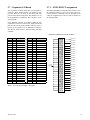
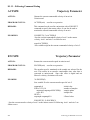
5.7 – Expansion I/O Board
5.7.1 EXIN/EXOUT assignments
5.7.2 BCD assignments
5.8 – Digital I/O Board
5.8.1 Input Connector
5.8.2 Output Connector
5.8.3 Internal Power Supply
5.9 – MX2 and MX6 Power Supply Board
5.9.1 AC Input
5.9.2 EXIN/EXOUT assignments
5.9.3 BCD assignments
5.10 – MX2A and MX6A Power Supply Board
5.10.1 AC Input
5.10.2 Input Connector
5.10.3 Output Connector
5.10.4 Internal Power Supply
5.11 – MX8 Power Supply Board
5.11.1 AC Input
5.12 – MX2 Outline
5.13 – MX6 Outline
5.14 – MX8 Outline
5.15 – MX & Servo Amplifier Connection Diagram
6 – Motion Controller Programming Interface
6.1 – Programming
6.1.1 General Description of Programming
6.1.1.1 What is Programming?
6.1.1.2 What’s in a Program
6.1.1.3 How is the Controller Programmed?
6.1.2 What are “Host Commands”?
6.1.3 Memory Types and Usage
6.1.4 References
6.2 – Multi-Tasking Operations
6.2.1 Multi-Tasking timing
6.3 – Motion Controller Programming Interface (MCPI)
6.3.1 Software Installation
6.3.2 Starting the MCPI Environment
6.3.2.1 The MCPI opening screen
6.3.3 Setting communication parameters
6.3.4 Creating a new project
6.3.5 The Task Editor
6.3.5.1 Document settings
6.3.5.2 Editor Tool Box
6.3.6 Terminal Emulation
6.3.6.1 Configuring Buttons
6.3.6.2 Configuring Fonts & colors
ii
PAGE
30
30
31
33
35
35
36
40
40
41
42
44
44
44
44
45
45
45
45
45
46
46
47
48
48
49
51
52
52
52
52
52
53
53
53
53
54
54
54
54
55
55
55
56
57
57
58
58
58
Table of Contents
SECTION & TITLE
6.3.7 Configuration & Setup Folders
6.3.7.1 Controller type Folder
6.3.7.2 System Folder
6.3.7.3 Profile Folder
6.3.7.4 Analog Inputs Folder
6.3.7.5 Encoder Folder
6.3.7.6 Open Loop Stepper Folder
6.3.7.7 Closed Loop Stepper Folder
6.3.7.8 Servo Drive Folder
6.3.7.9 Travel Limit Folder
6.3.7.10 Mechanical Home & Mark Registration Folder
6.3.7.11 I/O Folder
6.3.8 Preparing User Project for Execution
6.3.8.1 Project Source Code
6.3.8.2 Compiling a Project
6.3.8.3 Downloading a Project
6.3.8.4 Uploading Source Code
6.3.9 Downloading an Operating System
6.3.10 Other Menus
6.3.10.1 Project Menu
6.3.10.2 Utility Menu
6.3.10.3 Window Menu
6.3.10.4 Help Menu
6.3.11 Project Command Buttons
7 – Software Reference Guide
7.1 – SEBASIC Conventions
7.1.1 Arithmetic Operators
7.1.2 Logical Operators
7.1.3 Relationship Operators
7.1.4 Basic Data Types
7.1.5 Case Sensitivity in Statements & Commands
7.1.6 Program Limits
7.1.7 Numeric Formats and Range
7.1.8 Program Comments
7.1.9 Axis Related Command Syntax
7.1.9.1 Definitions Used in the Syntax Description
7.1.9.2 Syntax Descriptions
7.2 – Programming Command Grouped by Functions
7.3 – Programming Command Summary (alphabetical list)
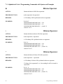
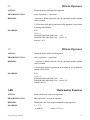
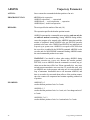
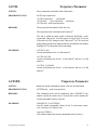
7.4 – Alphabetical List of Programming Commands with Syntax and Examples
&
|
^
>>
<<
ABS
ABSPOS
ACCEL
ACTSPD
ANALOG
AND
ARC
ASC
ATN
Table of Contents
PAGE
59
59
59
59
60
60
60
60
60
60
61
61
61
61
61
62
62
62
62
62
63
63
63
63
65
66
66
66
66
66
66
67
67
67
67
67
68
69
73
78
78
78
78
79
79
79
80
81
81
82
83
84
84
85
iii
Alphabetical List of Programming Commands with Syntax and Examples CONTINUED
SECTION & TITLE
ATN2
BCD
BOOST
BUSY
CAPPOS
CAPTURE
CHR$
COMMON
COS
DATA
DECEL
#DEFINE
DELTACAPPOS
DIM
DIST
DO … LOOP
DONE
DRVREADY
ENCBAND
ENCERR
ENCFOL
ENCMODE
ENCPOS
ENCSPD
END
ERR
ERRAXIS
ERRTRAP
EVENT1
EVENT2
EXIN
EXOUT
FEEDRATE
FOLACCDIST
FOLDCCDIST
FOLERR
FOLINPUT
FOLJOG
FOLMAXRATIO
FOLMINRATIO
FOLMOVE
FOLMOVEREG
FOLOFFSET
FOLOFFSETDIST
FOLRATIO
FOLRATIOINC
FOLSTARTDIST
FOLSYNC
FOLSYNCDIST
FOLTRIG
FORMAT
FOR … NEXT … STEP
GETCHAR
iv
PAGE
85
86
86
86
87
88
89
89
89
90
90
91
92
93
93
94
95
96
97
97
97
98
98
98
99
100
102
102
103
104
105
106
107
107
107
108
108
108
109
109
109
110
110
110
111
111
111
112
112
112
113
114
115
Table of Contents
Alphabetical List of Programming Commands with Syntax and Examples CONTINUED
SECTION & TITLE
GOSUB … RETURN
GOTO
HARDLIMIT
HARDLIMNEG
HARDLIMPOS
HEX$
HVAL
IF … THEN … ELSE IF … ELSE … END IF
IN
INCHAR
#INCLUDE
INPUT
INSTR
INTLIM
JOG
JOGSTART
JOYSTICK
KAFF
KD
KI
KP
KVFF
LCASE$
LEFT$
LEN
LINE
LOF
LOG
LOWSPD
MAXSPD
MID$
MOD
MOTIONSTATE
MOVE
MOVEHOME
MOVEREG
NOT
NVR
NVRBIT
NVRBYTE
OPTION DECLARE
OR
OUT
OUTLIMIT
PATH … PATH CLOSE … PATH END
POINT
POSERR
POSMODE
PRINT
PRINT USING
PROFILE
RADIUS
READ
Table of Contents
PAGE
115
116
117
118
118
118
119
120
121
121
122
122
123
123
124
124
125
126
126
126
126
127
127
127
127
128
129
129
129
130
130
131
131
132
133
135
137
137
138
139
139
140
141
142
143
144
144
145
146
147
150
151
151
v
Alphabetical List of Programming Commands with Syntax and Examples CONTINUED
SECTION & TITLE
REDUCE
REGLIMIT
REM ‘
RESET
RESTORE
RIGHT$
SETCOM
SHIFT
SIGN
SIN
SOFTLIMIT
SOFTLIMNEG
SOFTLIMPOS
SPEED
SQRT
STOP
STOPERR
STR$
STRING$
TAN
TIMER
TIMER2
TOLERANCE
UCASE$
VAL
VELOCITY
WAIT
WAITDONE
WARNING
WNDGS
7.5 Host Commands Grouped by Functions
7.6 Host Commands Summary (alphabetical list)
7.7 Host Commands – Alphabetical Listing
<n
?
ABSPOS
ACCEL
ANALOG
ARC
AXISBRD
AXSTAT
BACKSPACE
BCD
BUSY
CAPPOS
CAPTURE
CTRL-A
CTRL-C
DECEL
DELTACAPPOS
DIR
DRVREADY
ENCBAND
vi
PAGE
152
152
153
153
153
154
154
155
155
155
156
157
158
159
160
160
160
161
161
161
162
162
163
163
164
164
164
165
166
166
167
169
172
172
172
173
173
174
174
174
175
175
175
176
176
177
177
177
178
178
179
179
180
Table of Contents
Host Commands – Alphabetical Listing CONTINUED
SECTION & TITLE
ENCERR
ENCFOL
ENCMODE
ENCPOS
ENCRES
ENCSPD
ERASE
ERR
ERRAXIS
ERRM
ESC
EVENT1
EVENT2
EXIN
EXOUT
FILTER
FOLERR
FREE
FREEMEM
HARDLIMNEG
HARDLIMPOS
IN
INTLIM
JOG
JOGSTART
KAFF
KD
KI
KP
KVFF
LINE
LOAD
LOWSPD
MAXSPD
MOVE
MOVEHOME
MOVE REG
NVR
NVRBIT
NVRBYTE
OUT
OUTLIMIT
POSERR
POSMODE
PROFILE
REGLIMIT
RESET
REVISION
RUN
SNVR
SOFTLIMNEG
SOFTLIMPOS
SPEED
Table of Contents
PAGE
180
181
181
182
182
182
183
183
184
185
186
186
187
187
188
188
189
189
190
190
190
191
191
192
192
192
193
193
194
194
195
195
195
196
196
197
197
197
198
198
198
199
199
200
200
201
201
201
202
202
203
203
204
vii
Host Commands – Alphabetical Listing CONTINUED
SECTION & TITLE
STOP
STOPERR
UNIT
VELOCITY
WARNING
WNDGS
XON XOFF
8 – FOLLOWING
8.1 – Following Description
8.1.1 Follower Definition
8.1.1.1 Analog Following
8.1.1.2. Encoder Following
8.1.1.3 Command & Variable Following
8.1.2 Following Ratio
8.1.3 Follower Motions
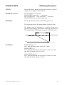
8.1.4 Basic Following States
8.1.4.1 Following Trigger
8.1.4.2 Follower Start Delay Distance
8.1.4.3 Follower Acceleration
8.1.4.4 Follower Synchronization
8.1.4.5 Follower Deceleration
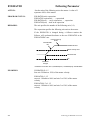
8.1.5 Advance/Recede Cycle
8.1.5.1 Offset Wait Distance
8.1.5.2 Offset Velocity Limits
8.1.5.3 Offset Distances
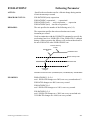
8.1.6 Following Program Template
8.1.7 Distance Measurements
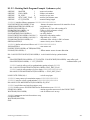
8.1.8 Cut to Length Example
8.1.8.1 Cut to Length Program Example
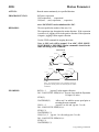
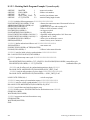
8.1.9 Rotating Knife Example
8.1.9.1 Rotating Knife Cycle
8.1.9.2 Rotating Knife Program Example (advance cycle)
8.1.9.3 Rotating Knife Program Example (recede cycle)
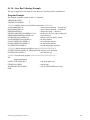
8.1.10 Gear Box Following Example
8.1.11 Following Command Listing
ACTSPD
ENCSPD
FOLINPUT
FOLTRIG
FOLSTARTDIST
FOLACCDIST
FOLDCCDIST
FOLRATIO
FOLRATIOINC
FOLJOG
FOLMOVE
FOLMOVEREG
STOP
FOLSYNC
MOTIONSTATE
FOLMAXRATIO
FOLMINRATIO
viii
PAGE
204
205
205
206
206
207
207
209
210
210
210
210
210
211
211
212
212
212
212
212
212
213
213
213
213
215
215
216
217
218
218
221
222
223
224
224
224
225
226
227
228
229
230
231
232
233
234
235
235
236
238
239
Table of Contents
Following CONTINUED
SECTION & TITLE
FOLOFFSET
FOLOFFSETDIST
FOLSYNCDIST
8.1.11 Follower Exercise
9 – Servo Drive
9.1 – Servo Control
9.1.1 Servo Tuning
9.1.1.1 System Folder
9.1.1.2 Encoder Folder
9.1.1.3 Servo Drive Folder
9.1.1.4 Servo Tuning Environment
9.1.1.5 Auto Tuning
9.1.1.6 Manual Tuning Adjustment
9.1.1.6.1 Adjustment based on auto tuning calculation
9.1.1.6.2 Fully Manual Adjustment
9.2 – Servo Drive Command Listing
FOLERR
INTLIM
KAFF
KD
KI
KP
KVFF
OUTLIMIT
STOPERR
WNDGS
10 – Stepper Drive
10.1 - Stepper Features
10.2 - Open Loop Stepper Folder
10.3 - Closed Loop Stepper Folder
10.4 - Encoder Folder
10.5 - Special Programming Notes for Closed Loop Stepper Operation
10.6 - Stepper Command Listing
BOOST
ENCMODE
FOLERR
LOWSPD
REDUCE
STOPERR
WNDGS
11 – Data Logging
11.1 – Data Logging
11.1.1 Parameter & Trigger Setup
11.1.1.1 Parameter List Descriptions
11.1.2 Data Transfer
11.1.3 View Data
Table of Contents
PAGE
240
242
243
244
249
250
250
251
251
251
252
253
256
257
257
261
261
262
262
263
264
265
266
266
267
268
269
270
270
271
271
272
273
273
274
275
275
276
277
278
279
280
280
280
281
281
ix
SECTION & TITLE
12 – Debug Environment
12.1 – Setting Project Debugging
12.2 – Task Debugging
12.2.1 Debug Program Execution
12.2.2 Breakpoint Setting/Clearing
12.2.3 Terminal Window
12.2.4 Watch Variables
12.2.5 Exit Debug Environment
PAGE
279
280
280
281
281
281
281
281
13 – Application Examples
283
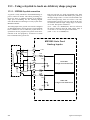
13.1 – Using Joystick to Teach an Arbitrary Shape Program
13.1.1 MX2000 Joystick Connection
13.1.2 Example Description
13.1.3 Main Section
13.1.4 Teach Section
13.1.5 Print Program Section
13.1.6 Execute Program Section
13.2 – Arbitrary Continuous Motion
13.2.1 Example Program
13.3 – Changing Velocity During Motion
13.3.1 Example Program
13.4 – Glue Application on a Gasket
13.4.1 Example Program
13.5 – Spring Winding Machine
13.5.1 Example Program
13.6 – Two Axis Conveying System
13.6.1 Example Program
13.7 – Optional Programming Environments
13.7.1 MX2000 CAD-To-Motion
284
284
285
285
285
285
285
289
290
291
291
292
292
294
295
296
296
296
296
14 – Troubleshooting Guide
297
14.1 – Status Indicator Lights
14.1.1 Power LED
14.1.2 Fault LED
14.1.3 Busy LED
14.2 – Serial Communications
14.3 – If you can not access Axis I/O
398
398
398
398
398
398
15 – Glossary
299
x
Table of Contents
List of Illustrations
Illustration or Chart
Section
PC receiver Baud Rate Chart
3
General Application Overview
4
MX 2000 System Block Diagram
5
Dual Axis Board
Dual Axis Interface board selection chart
5
Stepper Drive Connection Diagram
5
Servo Drive Connection Diagram
5
Encoder Connector signal description & electrical specification chart
5
Encoder Equivalent Circuit Diagram
5
Encoder Pulse and Direction connection Diagram
5
Axis I/O Connector signal description & electrical specification chart
5
Axis I/O Equivalent Circuit Diagram
5
Axis I/O Connection Diagram
5
Stepper Drive Connector signal description & electrical specification chart 5
Stepper Drive Equivalent Circuit Diagram
5
Analog Drive Connector signal description & electrical specification chart 5
Analog Drive Equivalent Circuit Diagram
5
Dual Axis Interface Panel and Card Diagram
5
32 bit DSP Board
Auxiliary Serial Port signal description chart
5
Auxiliary Serial Port Equivalent Circuit Diagram
5
Auxiliary Serial Port RS485 connections to a control panel
5
Auxiliary Serial Port RS232 connections to a control panel
5
Host Serial Port dip switch setting chart
5
Host Serial Port signal description chart for RS485 connector
5
Host Serial Port signal description chart for RS232 connector
5
Host Serial Port Equivalent Circuit Diagram RS232/RS485 position
5
Daisy Chaining MX2000 Controllers Diagrams
5
Auto Execute selection chart (SEL inputs)
5
DSP Card Inputs signal description & electrical specification chart
5
DSP front Panel Diagram
5
DSP Input connections for Sinking & sourcing chart
5
DSP card Inputs equivalent Circuit Diagram
5
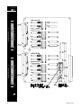
Expansion I/O Board
Expansion I/O assignment chart
5
Expansion I/O Connector pin outs Diagram
5
Expansion I/O connection to OPTO-22 Module rack Diagram
5
OPTO-22 Manufacturer’s chart
5
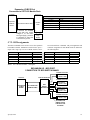
Expansion I/O BCD bank assignment chart
5
Expansion I/O BCD bank Connection diagram (Warner Electric Interface) 5
Expansion I/O BCD bank Connection diagram (BCD switch banks)
5
Expansion I/O BCD bank Signal Description & Electrical Specification chart 5
Expansion I/O Equivalent Circuit Diagram
5
Expansion I/O front Panel & Card Diagram
5
Digital I/O Board
Digital I/O Sink/Source Jumper Position Diagram
5
Digital I/O Input Signal Description & Electrical Specification chart
5
Digital I/O Input Sink/Sourcing Connection Diagrams
5
Digital I/O Output Signal Description & Electrical Specification chart
5
Digital I/O Output Sink/Sourcing Connection Diagrams
5
Digital I/O Internal Supply Signal Description chart
5
Digital I/O Equivalent Circuit Diagram
5
Digital I/O Panel and Circuit Card
5
Table of Contents
Page
10
18
23
24
24
24
25
25
25
26
26
26
27
27
28
28
29
30
30
30
30
31
31
31
31
32
33
33
34
34
34
35
35
36
36
36
36
37
38
38
39
40
40
40
41
41
42
42
43
xi
Illustration or Chart
MX2 & MX6 Power Supply Board
MX2 & MX6 panel
AC input Description and Lead color chart
EXIN & EXOUT assignments chart
BCD assignment chart
MX2 outline
MX6 outline
MX2A & MX6A Power Supply Board
MX2A & MX6A panel
AC input Description and Lead color chart
Input connector description and electrical specification chart
Output connector description and electrical specification chart
Internal Power Supply description chart
MX2 outline
MX6 outline
MX8 Power Supply Board
MX8 panel
AC input Description and Lead color chart
MX8 outline
MX & Servo Amplifier Connection Diagram
MCPI
Multi Tasking diagram
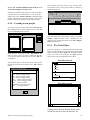
MCPI Opening Screen
New Project Screens
Task Editor Screens
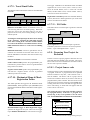
Document setting Screen
Editor Tool Box diagram
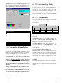
Terminal Emulation setup screen
Button configuration screens
Font & color configuration screen
System Folder screen
Profile Folder screen
Analog Inputs Folder screen
Travel Limit Folder screen
Mechanical Home & Mark Registration Folder screen
I/O Folder screen
System Folder screen
Encoder Folder screen
Servo Drive Folder
Open Loop Stepper Folder screen
Closed Loop Stepper Folder screen
Source Code selection screen
Upload Source Code screen
Download Operating System screen
Project Menu screen
Utility Menu Screen
Window Menu Screen
Help Menu Screen
Software Reference Guide
Arithmetic Operators
Logical Operator
Relationship Operator chart
Case sensitivity chart
Program limit charts
Numeric Format and Ranges
xii
Section
Page
5
5
5
5
5
5
44
44
44
44
47
48
5
5
5
5
5
5
5
45
45
45
45
45
47
48
5
5
5
5
46
46
48
49
6
6
6
6
6
6
6
6
6
6
6
6
6
6
6
9
9 & 10
9
10
10
6
6
6
6
6
6
6
54
55
55 & 56
56
57
57
58
58
58
59
59
60
60
61
61
251
251 & 271
251
270
271
61
62
62
62
63
63
63
7
7
7
7
7
7
66
66
66
66
67
67
Table of Contents
Software Reference Guide Continued
Illustration or Chart
ANALOG input chart
AND operator truth table chart
CAPTURE trigger chart
JOG Cycle diagram
LINE Cycle diagram
MOVE Cycle diagram
MOVEHOME Cycle diagram
MOVEREG Cycle diagram
NOT operator truth table chart
OR operator truth table chart
PROFILE velocity response diagram
SPEED change during motion diagram
Following
Basic Following States diagram
Basic Advance/Recede Velocity Profile diagram
Following Program Template chart
Cut to Length Cycle Velocity Profile Diagram
Cut to Length Cycle Positional Profile Diagram
Rotary Knife Cycle diagram
Rotary Knife advance cycle diagram
Rotary Knife recede cycle diagram
FOLTRIG diagram
FOLSTARTDIST diagram
FOLACCDIST diagram
FOLDCCDIST diagram
FOLRATIO diagram
FOLRATIOINC diagram
FOLMOVE Cycle diagram
FOLMOVEREG Cycle diagram
MOTIONSTATE diagram
FOLMAXRATIO diagram
FOLMINRATIO diagram
FOLOFFSET diagrams
FOLSYNCDIST diagram
Follower Exercise chart & diagram
Exercise Answers
Servo Drive
Servo Block Diagram
System Folder screen
Encoder Folder screen
Servo Drive Folder screen
Servo Tuning Environment screen
Auto Tuning screen
Stable response with integration during motion disabled diagram
Stable response with integration during motion disabled diagram
Response with different KVFF values diagrams
Stable and Unstable response diagrams
Manual adjustment response diagrams
Stepper Drive
Open Loop Stepper Folder screen
Closed Loop Stepper Folder screen
Encoder Folder
Table of Contents
Section
Page
7
7
7
7
7
7
7
7
7
7
7
7
82
83
88
124
128
132
133
136
137
140
150
159
8
8
8
8
8
8
8
8
8
8
8
8
8
8
8
8
8
8
8
8
8
8
8
212
214
215
216
216
219
220
220
226
227
228
228
230
231
233
234
236
238
239
240 & 241
243
244 & 245
246 & 247
9
9
9
9
9
9
9
9
9
9
9
250
251
251
251
253
253
255
255
255 & 256
256
258-260
10
10
10
270
271
271
xiii
Illustration or Chart
Data Logging Environment
Data Logging entry screen
Parameter & Trigger Setup screen
Data Transfer screen
View Data screen
Debug Environment
Debug setup screen
Debug Environment screen
Watch Variable screens
Application Examples
Joystick connection diagram
Arbitrary Continuous Motion machine diagram
Arbitrary path Positional Profile diagram
Changing Velocity during Motion diagram
Glue Application diagram
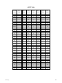
Glossary
ASCII Table chart
xiv
Section
Page
11
11
11
11
280
280
281
281
12
12
12
284
284
285
13
13
13
13
13
288
294
295
296
297
15
307
Table of Contents
Section 1
Important
Safety Information
Cautions & Warnings
1
1.1 – Cautions and Warnings
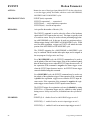
Before installing and operating your MX2000 motion
control product, it is extremely important both to you and
us here at Warner Electric that you read this section very
thoroughly and carefully. Your Slo-Syn product will deliver years of reliable, trouble-free, and most importantly,
safe operation if you heed the cautions and warnings outlined in this section, and follow the subsequent instructions in the remainder of this manual.
!
C au tio n
!
Throughout this section, and the remainder of this manual, two very important symbols will be used to identify
hazardous and potentially dangerous situations. These
symbols are the electrical shock indicator and the exclamation point. Both are always surrounded by a triangle as
shown.
C au tio n
The electrical shock symbol shown to the
left is used to indicate situations where
ELECTRICAL SHOCK hazards may
exist. These warnings must be followed to
ensure that YOU avoid electrocution that
could result in serious injury or death.
C au tio n
W arn ing
!
C au tio n
The exclamation point symbol shown to
the left is used to indicate situations other
than electrical hazards that may be potentially dangerous to either YOU or to the
product. Follow these warnings carefully
to avoid injury to you and damage to the
product.
The following is a partial list of precautions that must be
followed to ensure safe operation of the unit. Other more
specific precautions are indicated in the appropriate sections of this manual. As you read through the manual, pay
particularly close attention to these cautions and warnings
as they could save your life.
W arn ing
!
C au tio n
!
C au tio n
!
C au tio n
2
High voltages are present inside this unit.
An Electrical shock hazard exist that may
cause serious injury or death if this unit is
operated without its protective cover in
place.
Be certain the power has been removed
for a minimum of 5 minutes before any
service work or circuit board configuration changes are performed. This assures
that the power supplies are at zero.
Do not exceed the voltage or current ratings of the various inputs and outputs;
Please read the electrical specification in
Section 5. This will protect the circuitry
and components from accidental damage.
In order to provide the correct level of
protection in the unit, replacement fuses
must be the same exact style and ratings
as those originally installed in the unit.
!
!
C au tio n
!
C au tio n
!
C au tio n
Secure mounting and proper grounding of
both the MX2000 controller and the motors are essential for proper operation of
the system.
Be sure to mount the unit so there is adequate space around it for cooling airflow,
and observe the environmental limitations
for temperature and humidity.
The 24-volt dc power supply is limited to a
total current output of 0.75 amperes. Do
not exceed this rating, or the Controller
may shut down or work erratically as
the power supply’s current limiting circuitry operates to protect the unit from
overload.
Please follow good wiring practices and
keep low-level signal lines away from
power and motor wiring. It is best to use
shielded, twisted-pair cables for signal
lines, being sure to ground the shields at
one end. Doing this will help to avoid electrical noise interference problems.
If the unit is opened or disassembled, be
sure to treat the circuit cards as staticsensitive components to avoid damage due
to electrostatic discharge (ESD). Work
only in ESD protected areas, and it is best
not to touch the circuit conductors or
components unless you are wearing an
ESD-protective grounding strap.
It is your responsibility to follow the appropriate federal, state, and local electrical
and occupational safety codes in the application of this product.
NEVER wire the unit with the
power on! Serious injury as
well as damage to the unit may
result.
!
C aution
!
C au tio n
W arn in g
NONE of the inputs to the unit are to be
used as an EMERGENCY STOP in ANY
application. Although activation of certain
inputs will discontinue motion or disable
motor current, these are NOT designed as
fail-safe E-STOP inputs. Relying exclusively on inputs to the unit to cease motion
that could cause dangerous conditions is a
violation of Machine Safety Code (ref,
IEC204-1). Other measures such as mechanical stops and fail-safe brakes must be
used in these situations.
Cautions & Warnings
Section 2
Introduction
Introduction
3
2.1 - How To Use This Manual
Congratulations on the purchase of your new Warner
Electric MX2000 motion control product! Your programmable motion controller is a full-featured and flexible
product, yet it is fairly simple to apply it to your machine
control application. This manual is designed to guide and
assist you through the installation, programming, and operation of the controller. If you’re reading this, you understand the importance of familiarizing yourself with how
this product should be installed and operated. We strongly
recommend that you read through this manual until you are
comfortable with electrical connections and operating concepts of this unit.
Section 1, Important Safety Information, has cautions
and warnings information. This section should be read first
and the cautions and warnings should be followed.
Section 2, Introduction, has user prerequisite requirements, conventions used in the manual and Applications
Assistance information.
Section 3, Quick Start Installation Guide, contains the
minimum steps necessary to get up and running. The references to the appropriate manual sections where further
details can be found are included.
Section 4, Overview of System Operation, contains features and functions, along with a general overview of the
MX2000 system.
Section 5, Specification and Equivalent Circuits, has
specifications, setup requirements, connection diagrams,
and equivalent circuits for each board in the MX2000 system.
Section 6, Motion Control Programming Interface,
contains general Programming information. PC software
installation and execution, communications with the
MX2000 controller, and user project creation.
Section 7, Software Reference Guide, contains the basic
command conventions used and a listing with descriptions
of the Basic Program commands and Host Commands.
Section 8, Following, contains detailed information on
following, description of follower commands, application
examples, and listing and descriptions of the individual
follower commands.
Section 9, Servo Drive, contains general information on
servos, tuning, testing performance. Also a listing and descriptions of the individual servo commands.
Section 10, Stepper Drive, contains general information
on stepper drives, closed and open loop stepper setups.
Also a listing and descriptions of the individual stepper
commands.
Section 11, Data Logging, describes how to data log
MX2000 parameters.
Section 12, Debug Environment, describes how to debug
a user’s task.
4
Section 13, Application Examples, contains descriptions of applications with example programs for them.
Section 14, Troubleshooting Guide, has helpful hints
on troubleshooting problems.
Section 15, Glossary, contains a glossary of terms used
in the manual.
2.2 – What you need to know first
This manual is written in a simple and easy to follow
format that should be suitable for both new and experienced motion control users. In order to get the most out
of your SLO-SYN Programmable Motion Controller, we
assume the user will be knowledgeable in the following
areas:
Basic electrical and electronics skills, including preparing and following an equipment wiring diagram or
schematic.
The basics of motion control system applications, such
as torque, speed, move distance, and how to structure a
motion task into move segments and input/output control.
Some familiarity with elementary computer programming, including defining the problem to be solved and
coding it in a computer language.
2.3 – Conventions used in this manual
Motor rotation direction (CW and CCW) is properly
oriented when viewing the motor from the end opposite
the mounting flange.
Please refer to the Glossary section for detailed descriptions of terms such as sink and source I/O, various motion terms, etc.
2.4 - Applications Assistance
Although this manual represents a detailed compilation
of information regarding your SLO-SYN control product, sometimes questions may arise which will require
that you contact us, You now have a few options available to you when you need information regarding your
product or its application.
On the Internet at www.warnernet.com. Our multimedia enabled web site offers you information such as:
Free Software
TechFax fax on demand documents (1-800-234-3369)
HTML Product Selector, HTML Brand Selector
Product News and Links
Sales and Distribution Information
Product information and specifications
Many more features
2. By Phone. You may reach us by phoning our Motion
Control Application Engineering Department at telephone (800)787-3532 ext. 4751. Or call our main number at (860)585-4510. Both may be reached between the
hours of 8:00 AM and 5:00 PM (Eastern Time), Monday
through Friday. Technical personnel are available to assist you in getting your application up and running.
Introduction
Section 3
Quick Start
Installation Guide
Quick Start Installation Guide
5
3.1 – Switch and Jumper Settings
Before mounting and installing the MX controller, it is
best to set the switches and internal jumpers that govern
various operating features.
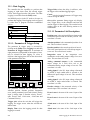
3.1.1 – Serial Communication
Baud Rate switches
The "BAUD" DIP switch located on the 32 bit DSP controller panel needs to be set to match the baud rate of the
host computer or terminal to which it is connected. The
factory default is 9600 baud; if this is not what is desired,
then set the switches toward one of the appropriate values
shown on the label. Valid selections are "9.6" (9600),
"19.2" (19,200), and "38.4" (38,400). If all switches are
"off" (toward the right), then the baud rate is set to 4800.
These switches are only read at power-up, hence changing
the baud rate requires a power-down, power-up cycle before the change takes effect.
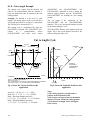
Although the controller's serial ports are configurable for
up to 38.4K baud, the serial communications may be limited by the PC. A PC may not be able to receive data
from the controller at baud rates above 9600. This limitation is due to the PC's inability, at the higher baud rates,
to read the received character in time, before another
character is received. If this happens, an OVERRUN
ERROR will occur. This problem will not exist if the
serial port's UART has hardware buffering. The following is a list of UART’ s commonly used on PC serial port
cards. The UART’ s marked with an * are buffered.
UART’ s:
8250, 16450, 16451, 16452, *16550, *16552
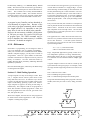
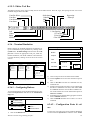
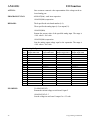
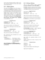
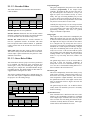
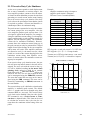
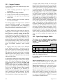
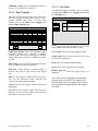
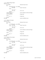
The following is a table of controller operations vs.
Maximum PC receiver baud rate.
OPERATION
UART
(no buffer)
UART
(buffer)
Load operating system
38400*
38400
Load user program
38400*
38400
Extract source code
9600
38400
Host commands
9600
38400
* The unbuffered UART will perform the first two
operations at the higher baud rate, since during these
operations, the controller does not transmit multiple
characters in succession.
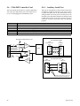
3.1.2 – Host RS232/RS485
The RS232/RS485 switch located on the 32 bit DSP controller panel needs to be set to match the communication
protocol of the host device, RS-232 or RS-485, to which
the Controller is connected. The factory default is for
"232" (RS-232); if RS-485 is desired, set the switch toward "485".
Serial communications format for the host port is "N-8-1",
or No parity, 8 data bits, and 1 stop bit.
6
3.1.3 – Auxiliary RS232/RS485
The communication protocol (RS232 or RS485) for the
Auxiliary Serial Port on the 32 bit DSP Card is selected
via a jumper on the card, immediately behind the port
connector. The factory default is for RS485; if RS232 is
desired, the DSP Card must be removed and the jumper
setting changed to the RS232 setting. Baud rate for this
port is set at 9600; if another Baud rate is desired, select it
via software using the "SETCOM" command. See Section 7 for further details on this command.
Serial communications format for the auxiliary port is "N8-1", or No parity, 8 data bits, and 1 stop bit.
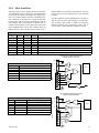
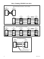
3.1.4 – Unit ID switch
The Controller is capable of being operated in a
"daisy-chain" fashion, with up to 9 units connected to a
single host. A connection diagram is depicted in Section
5.6.2 of this manual. Each unit in the chain requires a
unique identification number (ID #); this value is selected
by the "UNIT ID" selector switch on the DSP controller
board. The unit is shipped from the factory with 1 selected (the first unit in the chain). If needed, set the selector switch to a different value by using a small screwdriver. Set the pointer on the switch to the desired value, 1
to 9.
The controller scans the Unit ID switch during power up
or when a system Reset command is issued.
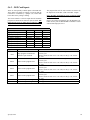
3.1.5 – 32 bit DSP Board Inputs
The four optically isolated inputs can either be sinking or
sourcing. A jumper on the card controls the selection,
located behind the DSP input connector. The factory setting is sinking; if sourcing is desired, the DSP card must
be removed and the jumper setting changed to the Source
position.
Hint: A CLR to COM jumper is required for motion
to occur.
3.1.6 – Dual Axis Inputs settings
The eight dedicated inputs on the Dual Axis Interface
Card can either be sinking or sourcing. A jumper on the
card controls the selection, located behind the AXIS I/O
connector. The factory setting is sinking; if sourcing is
desired, the Dual Axis card must be removed and the
jumper setting changed to the Source position.
3.1.6.1 – Dual Axis I.D. switches
Each axis card must be assigned a unique ID (1-4) and ID
1 must always be assigned to one of the boards. The axis
ID switch settings assign this ID. A table for the different
assignments is illustrated in Section 5.5 of this manual.
3.1.7 – Digital I/O settings
Setup & Installation
The digital I/O board inputs and outputs can either be
sinking or sourcing. Two jumpers on the card controls the
selection, located in the lower left corner of the board.
The factory setting is sinking; if sourcing is desired, the
Digital I/O card must be removed and the jumpers setting
changed to the Source position.
HINT: The Drive type for each axis must be selected in the System folder. Now the axes must be
assigned to a specific task. The Task assignment
item in the System folder is used for this purpose.
3.2 - Step-by-Step Start-Up Procedure
HINT: If the axis is a servo drive or closed loop
stepper the line count of the encoder must be entered
into the Encoder folder.
The MX2000 stepper/servo motor positioning system is a
sophisticated and versatile product. Setting up the system,
however, can be simple and straight-forward if the proper
steps are followed. Please use the step-by-step set up
guide below.
3.2.1 - Bench Set Up.
Before connecting your MX2000 and motors to your mechanical system or machine, we recommend that you
“bench test” the system. This will allow you to become
familiar with the wiring, programming and operation of
the system before installing it into your machine. This
may also prevent inadvertent damage to your mechanical
system if you make programming errors that cause unexpected motion. The bench set up can be used to perform
simple motions with an unloaded motor. To perform a
bench test, do the following:
1) Wire it up. Connect the servo drives as illustrated in
section 5.5.2, connect the stepper drives as illustrated
in section 5.5.1, connect the AC power, I/O and other
required signals per the wiring diagrams and instructions in section 5. BE SAFE!! Do not apply AC
power to the unit until you are sure of all connections. Initially, there is no need to connect all of the
wiring of your system together. Wire the AC line input, drives, motors and HOST communication ports.
This will be all you need to establish communications
to the unit and perform simple motion.
HINT: Don’t forget to wire the Enable and Ready
signals to the servo drive, see section 5.5.6 Analog
Drive Connector .
2) Load Software. You will need to use a PC to program the unit according to your requirements. First
you must load the MCPI software onto the PC from
the floppy disks provided with your unit. Simply in sert disk #1 and run the file SETUP.EXE. Once the
software is loaded, run it by double clicking on the
MCPI icon. See Section 6.3.1 for more details on the
MCPI installation process.
3) Create your Project. You can now create your new
Project. Your Project will contain Configuration information for your particular system, and also your
program Task’s that holds the user program written
in BASIC-like language. Read section 6 of this manual, and then step through the Configuration folders
and enter the appropriate data for your system, saving
the configuration when you are done. Don’t forget to
set up the serial port for your PC to the correct port
number and baud rate.
Setup & Installation
HINT: Motion is commanded in User Units. The
User Units per motor revolution item in the System
folder allows you to enter the value. Initially, it is
easiest to set this to 1. This will mean that move distances are in motor revolutions (e.g. move=1 moves
one revolution), speeds will be in revs/sec, and accelerations will be in revs/sec/sec. Later this can be
changed (e.g. to allow programming in inches on a
lead screw) to allow ease of programming once the
motor is installed into the mechanical system. All
move distances, speeds, and accelerations (or
decelerations), and encoder information are provided
in User Units, so be sure you understand this before
continuing.
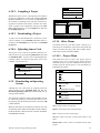
4) Compile and Download the project into the controller using the command buttons of the MCPI. Note
that initially, you can leave the Task blank and command motion using the Host Commands. Host
commands are entered in Terminal Mode from the
MCPI. Enter the terminal mode by clicking on the
Terminal command button on you screen. If your
system consists of stepper drives only go to step 8.
See Section 6.3.8.2 of this manual.
5) Tune the Servo axes. Before running the motor, the
controller compensation parameters (gains) must be
set. To aid in this task an automatic servo tuning
procedure is available. To enter the servo tuning
screen click on the servo tuning button. The default
values for auto-tuning procedure should work fine for
now. The motor may be tuned on the bench with no
load. Ensure that the motor is properly secured to
your work surface (bench). Note: Do not clamp the
motor anywhere except at the mounting flange.
Begin the auto-tuning process by selecting the servo
axis you desire to tune and then by clicking on the
Auto Tune button. A screen with the default values
will appear. Click on the OK button to use these settings. Next, click on the Measure System Gain button. The motor should bump , then the System Gain
value should update on the screen. Now click on the
Calculate Servo Gains button and the calculated
servo gain values will be displayed on the screen.
Click the Update Gains button, the servo should now
be locked in position. Verify this by manually trying
to turn the motor shaft. The servo should fight to stay
in position.
It’s now time to try a test move by entering profile
parameters. First click the Motion Setup button and
enter the desired Acceleration, Deceleration, Speed
and Move Distance in user units (e.g. revolutions by
7
default). When finished click the Done button. Now
make the motor move by clicking the Move Response button. The motor should complete the programmed profile and the position error plot should
appear on the screen. You may have to adjust the display time in order to see the whole move.
6) Repeat step 5 for all servo axes. Then click on the
Exit command button and OK when save parameter
screen appears.
7) Compile and Download the project into the unit by
clicking on the Compile and then the Download
command buttons of the MCPI. This will save the new
servo parameters to the MX2000 controller. Note that
initially, you can leave the Task blank and command
motion using the HOST Commands . Host commands
are entered in the Terminal Mode from the MCPI.
Enter the terminal mode by clicking on the Terminal
command button.
8) Make it move! Now that you have compiled and
downloaded your project into the unit, you are ready to
make the motor move. First you must enter the speed
at which you wish the motor to turn, such as 1 rev/sec.
Do this by typing speed(axis)=1<CR> (<CR> means
the Return or Enter key). Now enter the acceleration,
for example 50 revs/sec/sec by typing accel(axis)=
50<CR>. Set the deceleration to match by typing decel(axis)=50<CR>. Make sure to connect CLR to
COM for sinking I/O or CLR to +24V for sourcing
I/O on the DSP board or no motor motion will occur.
With the motor secured to the bench, you can now
command a move. If the axis you want to move is a
servo drive you must enable the drive first. This is accomplished by typing wndgs(axis)=1<CR>. To command an incremental move of 10 revolutions type
move(axis)=10<CR>. The designated axis motor
should now move 10 revolutions. If it does not, check
your wiring. Also verify your configuration settings.
In addition, check the motor direction to insure it
meets your requirements. The motor direction can be
reversed in the System folder if necessary.
Note: Axis is the desired axis you want to address.
9) Write a BASIC Program. Now that you have made
a simple move, you are ready to write your Task in
the MCPI BASIC-like language. Refer to Section 7
for a complete description of all of the Program
Commands. You can start by opening your Task and
entering the commands. First, let’s enter the exact
same commands that you used in the Terminal HOST
mode.
Enter
speed(axis)=1<CR>, accel(axis)=
50<CR>, decel(axis)=50<CR>, and move(axis)=10
<CR> commands as you did in step 8). If the axis is a
servo drive enter the WNDGS(axis)= 1<CR> command before the move command as you did in step
8). You must enter two more commands to tell the
unit that the program is done after it performs the
move.
Type
WAITDONE(axis)<CR>
and
END<CR> as the last lines of the program. Since
your program has changed, you must compile and
8
download it into the unit again for the changes to take
effect. If you receive compilation errors, check your
spelling and syntax with the information in Section 7.
10) Execute the Program. From the Terminal Host
Mode, click on the RUN button to make the motor
move 10 revolutions. If desired you can now add
lines to the program to perform more sophisticated
motion. For example, type x=10 <CR>. This assigns
the REAL variable “x” a value of 10. Change the
MOVE(axis)=10 line to MOVE(axis)=x. Now the
motor will move the designated axis whatever distance has been assigned to x. Recompile and download your program, then run it. It should operate the
same as before, but now the program is now using x
as the move distance in place of 10 as before. Change
the value of x to different distance values to verify
that it works correctly.
11) Expand the Program and Debug it. Now that you
have written a simple program, you can add more
complexity by adding more commands. You can do
complex looping, access I/O, and motion functions as
required. It will be helpful now to use the DEBUG
feature of the MCPI environment. Again, refer to
Section 12 for a detailed description of the debug
mode. If you compile your program in Debug Mode,
you can enter the debug screen as your program runs
and step through your code to verify proper operation. Once the code is functioning correctly, you
should re-compile in Release Mode as this will speed
up program execution.
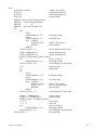
3.2.2 - Installation into Mechanical
System
Once you have tested everything out in a controlled environment, you may complete the installation into your
system. This will require making all the necessary wiring
connections for limit switches, additional I/O, analog in puts, encoder, etc. The first thing that must be done is to
retune your servo axes, repeat steps 5 to 7. Start simple!!
Just as you started with a simple move on the bench, you
should start simple here as well, slowly adding comple xity as you debug your code and gain more confidence in
programming. You may use the Debug Mode to help in
this process. See Section 12 Debug Environment for
more information.
Setup & Installation
3.3 - Installation
Ÿ
Ÿ
Ÿ
Ÿ
Ÿ
Ÿ
Ÿ
Ÿ
Ÿ
Ÿ
Ÿ
It is important to select a mounting location for you controller that will meet the environmental specifications
listed in Section 5.2. Avoid locations that expose the unit
to extremes of temperature, humidity, dirt/dust, or vibration.
Also, it is best to avoid areas with high "electrical noise."
This will help to prevent misoperation due to electromagnetic interference. Please refer to Section 3.4.1 for general guidelines on selecting a location for your controller
where it will be less susceptible to EMI/RFI problems.
When mounting the unit near other apparatus, such as
inside an electrical cabinet or enclosure, please leave at
least 2 inches of space on all sides for proper cooling.
Mounting brackets are supplied to attach the controller to
a vertical surface. The MX2000-8 can also be mounted in
a standard 19 inch rack configuration by removing the
mounting brackets and rotating them 180E. Please refer
to section 5.12, 5.13, and 5.14 for overall dimensions and
mounting hole locations for the MX2000-2, -2A, -6, -6A,
and -8 respectively.
3.4 - WIRING THE CONTROLLER
FOR OPERATION
Section 5 Specifications and Equivalent Circuits shows
how to wire up the individual connectors, depicts equivalent circuits for each connector, describes connector labels, defines connector signal characteristics, defines AC
electrical ratings of the System, and defines mechanical
and environmental specifications. Be sure to observe the
listed electrical ratings of the ac input and the various I/O
circuits; this will ensure proper, reliable operation of your
controller.
3.4.1 – General Wiring Guidelines
SLO-SYN 2000 controls and drives use modern solidstate digital electronics to provide the features needed for
advanced motion control applications. Some user equipment may produce electromagnetic interference (EMI, or
electrical noise) that can cause inappropriate operation of
the digital logic used in the control, drive, or other computer-type equipment in the user’s system.
In general, any equipment that causes arcs or sparks or
that switches voltage or current at high frequencies can
cause interference. In addition, ac utility lines are often
polluted with electrical noise from sources outside a
user’s control (such as equipment in the factory next
door). Some of the more common causes of electrical
interference are:
Setup & Installation
power from the utility ac line
relays, contactors and solenoids
light dimmers
arc welders
motors and motor starters
induction heaters
radio controls or transmitters
switch-mode power supplies
computer-based equipment
high frequency lighting equipment
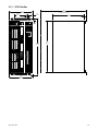
dc servo and stepper motors and drives
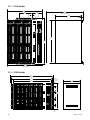
The following wiring practices should be used to
reduce noise interference.
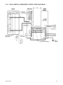
1 ) Solid grounding of the system is essential. Be sure
that there is a solid connection to the ac system earth
ground. Bond the drive case to the system enclosure.
Use a single-point grounding system for all related
components of a system (a “hub and spokes” arrangement). Keep the ground connections short and direct.
2) Keep signal and power wiring well separated. If
possible, use separate conduit or ducts for each. If the
wires must cross, they should do so at right angles to
minimize coupling.
Note: Power wiring includes ac wiring, motor wires,
etc. Signal wiring is inputs and outputs (I/O), encoder
wiring, serial communications (RS232 lines), etc.
3) Use shielded, twisted-pair cables for the drive to
motor wiring.
BE SURE TO GROUND THE
SHIELD AT THE DRIVE END.
4)
Suppress all relays to prevent noise generation.
Typical suppressors are capacitors or MOV‘s. (See
manufacturer’s literature for complete information).
Whenever possible, use solid-state relays instead of
mechanical contact types to minimize noise generation.
In some extreme cases of interference, it may be necessary to add external filtering to the ac line(s)
feeding affected equipment, or to use isolation
transformers to supply their ac power.
NOTE: Superior Electric makes a wide range of ac
power line conditioners that can help solve electrical
interference problems. Contact 1-800-SUP-ELEC
(1-800-787-3532) for further assistance.
9
(This page intentionally left blank)
10
Setup & Installation
SECTION 4
OVERVIEW OF
SYSTEM OPERATION
Overview
11
4.1 – Features and Functions
The controller is based on the Texas Instruments
TMS320C31 32 bit, 33MHZ Digital Signal Processor
(DSP). It can control from 2 to 8 stepper or servo drives,
plus 350 I/O points. Each pair of axes is supervised by a
powerful Application Specific Integrated Circuit (ASIC) that
is custom programmed for the controller. This state-of-theart computer hardware gives the controller plenty of
processing power to coordinate motion and simultaneously
execute multi-tasks up to seven complex motion and inputoutput (I/O) user tasks. The basic two-axis system consists
of three major circuit cards that communicate via a passive
back plane and are housed in a rugged enclosure.
MX2 or MX6 system
!
!
!
!
!
90 to 265 VAC 50/60 Hz input.
Built-in AC line filter and MOV’s.
Power-on LED.
Built in 24-volt dc @ 750 ma. supply for I/O.
50-pin header for interfacing to as many as 24 OPTO22 style I/O, or up to 4 BCD switch banks.
MX2A or MX6A system
!
!
!
!
!
!
90 to 265 VAC 50/60 Hz input.
Built-in AC line filter and MOV’s.
Power-on LED.
Built in 24-volt dc @ 750 ma. supply for I/O..
16 optically isolated inputs.
8 optically isolated outputs.
MX8 system
!
!
!
!
!
!
Dual Ac voltage range.
90 to 132 VAC 50/60 Hz input.
175 to 264 VAC 50/60 Hz input.
Built-in AC line filter and MOV’ s
Power-On LED
Built in 24-volt dc @ 750 ma. supply for I/O.
DSP Controller Card
! 256 Kbytes of Flash memory available for user
program storage.
! Two serial ports configurable as an RS232 or RS485
device.
! 4 optically isolated inputs.
12
Dual Axis Card
! 2 analog outputs capable of a ±10 volt DC swing.
! 4 analog inputs capable of a ±10 volt DC swing.
! 8 dedicated optically isolated inputs for limits and
triggers.
! 2 servo or stepper drive interfaces.
! 2 encoder interfaces.
Digital I/O Card
!
!
!
!
24 optically isolated inputs.
16 optically isolated inputs.
Removable connectors with screw terminals.
24 volt power supply access.
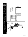
Expansion I/O Card
! 50-pin header for interface to as many as 48 OPTO-22
style I/O, or up to 8 BCD switch banks.
Programming Features
! English language, BASIC-like coding.
! Full math capability, including trig functions, logs, and
square root.
! Boolean logic functions (and, or, xor, not).
! Complex motions (arc, path, line).
! Simple Motions (move, jog).
! Trigger motions (movehome, movereg).
! Position Following.
! Changing Velocity during motion.
! Position Capture from a trigger.
! Subroutines , nested up to 16 levels.
! Multi-tasking of up to 7 concurrent tasks.
! String manipulation (for message handling).
! Program control functions (for-next, if-then-else ifelse, goto, do-while, etc).
! Macro substitution (#define) for user-friendly text
naming of I/O, etc.
! Complex expressions (using parentheses).
! Multi dimension Arrays.
! 2 Timers per task.
! Complete error handling and warning messages.
Overview
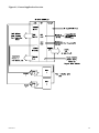
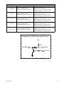
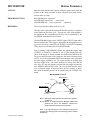
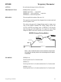
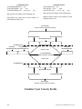
4.2 - General Overview
The Programmable Motion Controller is a powerful, DSPbased machine controller that is capable of far more than
simply moving motors. This section is intended to give the
user an overview of the controller's many capabilities
including all the functions and features users expect for
controlling motion. There are a wide variety of inputs and
outputs and software features that, in many cases, allow the
controller to operate an entire sophisticated machine. Figure
4.1 shows a typical 2-axis application. Section 5 has details
on setting up and wiring the unit.
Of special note is the ease of communication with either
"intelligent" or "dumb" operator interfaces. The controller
does not require the use of any operator interface panel or
host computer to operate as a stand-alone system. Simple
switch interfaces via axis I/O or expansion I/O will often
suffice for controlling a machine that does not need
extensive interaction with the operator for setup information
or message display. BCD switches are often used to enter
numeric data for simple setup. However, using a panel with
a keypad and display gives more flexibility and sometimes
easier and more "user-friendly" machine operation.
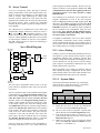
4.2.1 - Serial Communications
Communication with the MX2000 controller is via two
serial ports on the DSP Card. These serial ports can be
operated as an RS232 or RS485 device. The Host port is
used for programming and operating the unit. The Auxiliary
Port is used to communicate with an external serial device
during program execution. Use of these ports is covered in
more detail in Sections 5.6.1 and 5.6.2.
4.2.2 - Shutdown Input & Program
Select Inputs
The 32 bit DSP interface has four optically isolated inputs.
One of these inputs is used as a system shutdown or "motion
clear" input. The 3 remaining inputs allow selection of any
one of up to seven user programs that will be executed at
power-up or when a Reset command is issued. These inputs
can be sinking or sourcing. See Section 5.6.3 for more
details.
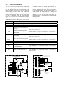
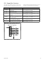
4.2.3 - Expansion I/O - BCD Port
An expansion I/O port is provided on the MX2 or MX6
Power Supply or optional Expansion I/O board. The I/O is
designed to interface to industry-standard "OPTO-22" style
high-power inputs and outputs.
(seven digits plus sign per bank). Warner Electric provides
standard switch banks for use with the controller. Users may
also combine BCD's and expansion I/O. See Sections 5.7
and 5.9 for more details.
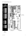
4.2.4 – Digital I/O
A digital I/O port is provided on the MX2A or MX6A
Power Supply or optional Digital I/O board. The I/O is
designed to operate with switches and relays. These inputs
and outputs can be sinking or sourcing. See Sections 5.8 and
5.10 for more details.
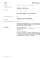
4.2.5 - Stepper Interface
Standard pulse and direction signals are provided on the
Axis Card for controlling most types of stepper drives.
Signals are compatible with drives up to 50,000 pulses per
revolution (1/250 micro-stepping), since the maximum pulse
rate is 1.99 MHz. See Sections 5.5.1 and 5.5.5 for more
details.
It is important to note that the controller can be easily
programmed in user units, such as inches or revolutions,
based on the motor/drive resolution and the machine's
characteristics. This is possible because of the controller's
extensive math functions. See Section 7 Software
Reference Guide for more details.
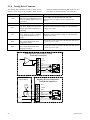
4.2.6 – Analog Drive
The analog outputs can be used as the torque command for
a servo drive. In addition a pair of drive enable output and
drive ready inputs have been provided.
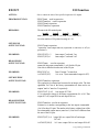
4.2.7 - Encoder Interface
Inputs from two incremental encoders are provided on the
Axis Card. The maximum count rate is 2 MHz. There is
5Vdc power available on this connector to power the
encoders. Wiring to this port is covered in Section 5.5.3.
4.2.8 - Axis I/O and Analog I/O
Inputs are provided on the Axis Card for two axes worth of
limit switches, home switches, and mark registration sensors.
(The latter two are connected to the "Event 1" and "Event
2" pins.) These can be configured for sink or source
operation. Also, there are two sets of analog inputs that can
be read under program control. These inputs may be used
for reading various types of sensors (temperature, pressure,
etc.) and then controlling index distance or motor speed
based on the value read. See section 5.5.4 for more details.
Alternatively, this port can be used to read BCD switches
Overview
13
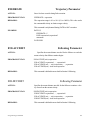
4.3 - Use of the Serial Ports,
"HOST" and "AUXILIARY"
The controller has two serial ports, which are identified as
"HOST" and "AUXILIARY". The "HOST" port, as its name
implies, is typically connected to a host computer such as an
IBM PC or compatible. The "AUXILIARY" port is intended
for use with an operator interface panel such as Warner
Electric's IWS series product line.
The "HOST" port is used for downloading the user's
application program and for direct control of the controller.
When using the MCPI programmable Interface, all
communication with the controller is via the "HOST" port.
In addition, all on-line debugging is accomplished using this
port. The "HOST" port also has the capability to "DAISY
CHAIN" to other controllers; this requires only one serial
port on a user's host computer to communicate to multiple
controllers. While the user's program could use the "HOST"
port for communication with any device that has a serial
port, it is recommended that the "HOST" port be reserved
for debugging the user's program and for communication
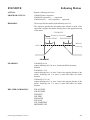
with the host computer.
Example:
PRINT #2,"Enter 6 digit part number"
INPUT #2, PART$
A message is displayed on the OIP screen prompting the
machine operator to enter a part number. The string variable
PART$ can now be examined (by the controller program) to
determine what type of process to perform. The information
provided by the operator can then be used to control the
process flow, ie. move distance, velocity, dwell, etc., for the
desired part number that the machine is processing.
While the process is in operation, messages can also be sent
back to the OIP, telling the operator the status of the
process. For example,
PRINT #2, "Coarse grind"
PRINT #2, "Finish grind"
will display the indicated messages on the OIP regarding the
grinding operation that is occurring.
The "AUXILIARY" port, while intended for use with an
operator interface panel (O.I.P.), can in fact communicate
with any device that has a serial port, such as counter units,
etc. The "AUXILIARY" port can send and receive standard
ASCII characters. The user's application program can
transmit a prompt or message using the "PRINT" statement
and wait for a response using the "INPUT" statement.
14
Overview
Figure 4.1, General Application Overview
Overview
15
This page left intentionally blank
16
Overview
Section 5
Specifications
And
Equivalent Circuits
Specifications
17
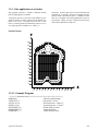
5.1 – Mechanical Specification
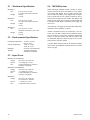
5.4 – MX2000 System
MX2000-2
Size:
When ordering an MX2000 system a number of factors
must be taken into account. The number of axes, number
of I/O points and whether the I/O requires optical isolation. The MX-2 and MX-6 power supplies have 24 expansion I/O points that are not optically isolated but can be
interfaced to an OPTO-22 rack module. The MX-2A and
MX-6A power supply has 16 optically isolated inputs and
8 optically isolated outputs. The MX-8 power supply has
no I/O on it.
Weight:
MX2000-6
Size:
Weight:
MX2000-8
Size:
Weight:
5.34” X 10.63” X 7.48”
135.6 mm X 270 mm X 190 mm
8.25 lbs
3.75 Kg
9.34” X 10.63” X 7.48”
237.3 mm X 270 mm X 190 mm
11.0 lbs
5.0 Kg
19.0” X 10.63” X 7.54”
482.6 mm X 270 mm X 191.6 mm
12.0 lbs
5.45 Kg
5.2 – Environmental Specification
Operating Temperature:
Storage Temperature:
Humidity:
Altitude:
+32° F to +122° F
0° C to +50° C
-40° F to +167° F
-40° C to +75° C
95% max. non-condensing
10,000 feet maximum
3048 meters maximum
An Isolated 24 volt supply has been provided which has a
maximum current capability of 750 ma.
Another consideration for the I/O connections is the connector style. The MX-2, MX-6 and any additional expansion I/O cards have 50 pin mass termination connections
and are not optically isolated. The MX-2A, MX-6A and
any additional digital I/O card have plug-in screw terminations and are optically isolated.
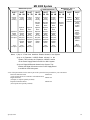
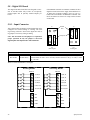
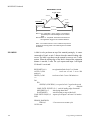
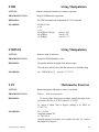
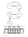
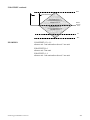
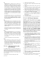
A System Block diagram with all the different combination to make up an MX2000 controller has been provided
on the next page.
5.3 – Input Power
MX2000-2 or MX2000-2A
voltage:
90 to 265 VAC, 50/60 hz
current:
< 0.5 Amps @ 115 VAc
fuse:
2 Amp (normal blow), 250VAC,
3AG type (2 required)
MX2000-6 or MX2000-6A
voltage:
90 to 265 VAC, 50/60 hz
current:
< 0.5 Amps @ 115 VAc
fuse:
2 Amp (normal blow), 250VAC,
3AG type (2 required)
MX2000-8
voltage:
90 to 132 VAC, 50/60 hz
175 to 254 VAC, 50/60 hz
current:
< 3 Amps @ 115 VAc
fuse:
3 Amp (slow blow), 250VAC
18
Specifications
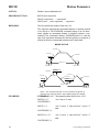
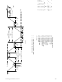
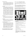
MX 2000 System
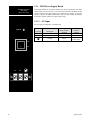
MX2000-8 Expansion
MX2000-2(A), -6(A), -8
Base System
MX2000-6(A) Expansion
SLOT
8C
SLOT
8A 8B
SLOT
7A 7B
SLOT
6A 6B
SLOT
5A 5B
SLOT
4A 4B
SLOT
3A 3B
SLOT
2
SLOT
1
Contains:
1 of the
following
Contains:
1 of the
following
Contains:
1 of the
following
Contains:
1 of the
following
Contains:
1 of the
following
Contains:
1 of the
following
Contains:
Contains:
Dual-Axis
Interface
Board
Dual-Axis
Interface
Board
Dual-Axis
Interface
Board
Dual-Axis
Interface
Board
MX-2 and
MX-6
Contains:
Power Supply
Board
Including
I/O-BCD
Interface
Expansion
I/O-BCD
Board
and 1 inch
filler panel
1 Inch
filler panel
Digital I/O
Board
Digital I/O
Board
Digital I/O
Board
Digital I/O
Board
Digital I/O
Board
Expansion
I/O-BCD
Board
and 1 inch
filler panel
Expansion
I/O-BCD
Board
and 1 inch
filler panel
Expansion
I/O-BCD
Board
and 1 inch
filler panel
Expansion
I/O-BCD
Board
and 1 inch
filler panel
Expansion
I/O-BCD
Board
and 1 inch
filler panel
2 Expansion
I/O-BCD
Boards
2 Expansion
I/O-BCD
Boards
2 Expansion
I/O-BCD
Boards
2 Expansion
I/O-BCD
Boards
2 Expansion
I/O-BCD
Boards
2 Inch
filler panel
2 Inch
filler panel
2 Inch
filler panel
2 Inch
filler panel
32 Bit DSP
Controller
MX-2A &
MX-6A
Contains:
Power
Supply Board
Including
Digital I/O
Interface
MX-8
Contains:
Power Supply
Notes: 1) Up to 4 Dual Axis Interfaces Boards allowed in the System.
2) Up to 4 Expansion I/O-BCD Board allowed in the
System. This includes the Expansion I/O-BCD section
on the Power Supply Board in an MX-2 or MX-6 system.
3) Up to 4 Digital I/O Boards allowed in the System. This
includes the Digital I/O section on the Power Supply Board
in an MX-2A or MX-6A system.
A list of the part numbers for the discrete part of the system has been provided for your convenience.
Dual-Axis Interface board
222420-001
(2 axis stepper and or servo interface with dedicated I/O)
Digital I/O board
222421-001
(24 inputs, 16 outputs optically isolated)
Expansion I/O-BCD board
222642-001
(48 I/O points non-optically isolated)
Specifications
19
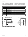
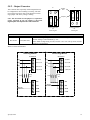
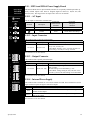
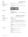
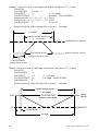
5.5 -Dual Axis Interface Card
This card contains the interfaces necessary to connect 2
motor drives to the MX2000 controller. A stepper drive
or servo drive can be interfaced to the controller. In addition 4 dedicated inputs and up to 2 analog inputs can
be interfaced to each axis.
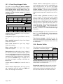
Up to four Axis cards can be plugged into an MX2000-8
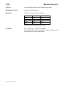
back plane. Each axis card must be assigned a different
id (1-4) and id 1 must always be assigned to one of the
boards. The factory setting is board Id 1. For proper operation, a Dual Axis board must always be plugged into
SW1 switch positions
C
B
A
On
On
On
On
On
Off
On
Off
On
On
Off
Off
Board
Id
1
2
3
4
Axes
Assigned
1&2
3&4
5&6
7&8
the MX2000 controller. The ID switches are located
behind the Analog output connector on the Dual Axis
card.
The 4 dedicated inputs for each axis are optically isolated and can be either sinking or sourcing inputs. This
selection is made on the Dual Axis Interface card by
plugging the select jumper into the desired position. See
the card layout diagram to locate the jumper. The factory
setting is Sink.
MX2000-2
System
Yes
Not available
Not available
Not available
MX2000-6
System
Yes
Yes
Yes
Not available
MX2000-8
System
Yes
Yes
Yes
Yes
Note: The “A” side is the odd axis connector and the “B” side is the even axis connector.
5.5.1 – Stepper Drive Connections
5.5.2 – Servo Drive Connections
The stepper drive connections are made to the STEPPER
DRIVE connector. If an encoder is attached to the stepper motor the Encoder connections are made to the ENCODER connector. An illustration of this is provided.
The signal descriptions and equivalent circuits of each
connector will be covered later on in this section.
The servo drive connections are made to the ANALOG
DRIVE connector. The encoder connections from the
motor are made to the ENCODER connector. An illustration of this is provided. The signal descriptions and
equivalent circuits of each connector will be covered
later on in this section.
Dual Axis Interface
Card
OPTO
OUT
PULSE
AGND
D IR
AW O
RDCE
D R IV E
BO OST
S te p p e r
D riv e
WNDGS
S te p p e r
M o to r
ANALOG DRIVE
STE PP ER D R IVE
D u a l A x is In te rfa c e
C a rd
Command
EN +
EN RDY +
Sensors
Servo
Drive
Windings
Servo
Motor
Control
RDY -
READY
100 milliamps maximum
1 0 0 m illia m p s m a x im u m
+5V
+5V
EN C O D ER
SHLD
A +
A B +
GND
O n ly R e q u ire d F o r
C lo s e d L o o p S te p p e r
ENCODER
SHLD
ENCODER
GND
A+
A-
Encoder
B+
B -
B-
B -
I+
B -
I-
Customers
Control
Scheme/Circuit
Thermal Switch +
Thermal Switch*
Thermal Switch -
* If the Servo Motor has thermal switches included it is recommended that these connections be made to a control circuit (Stop)
to indicate when a Motor Overtemp condition exists.
20
Specifications
5.5.3 –Encoder Connectors
The Encoder connector provides a means to interface an
encoder or pulse and direction input to the controller.
There are two identical connectors provided, one for
each axis. The encoder 5 volt output is restricted to 100
milli-amps of current per axis. We highly recommend
the use of twisted-pair (approximately 6 twists per foot)
shielded cable for all encoder wiring to minimize interference problems. The following signal should be
twisted together A+ with A-, B+ with B-, I+ with I- and
+5V with GND.
Encoder Connector
Signal Name
+5V
GND
SHLD
Description
+5 volts for the encoder
Signal ground for encoder
Connection to shield
A+
Encoder channel A+ input
A-
Encoder channel A- input
B+
Encoder channel B+ input
B-
Encoder channel B- input
I+
Encoder channel I+ input
I-
Encoder channel I- input
Electrical Specification
5 ±0.2 volts @ 100 ma per encoder
Not applicable
Not applicable
7.3 ma @ +5 volts
7.3 ma @ 0 volts
0 ma @ +5 volts
7.3 ma @ 0 volts
7.3 ma @ +5 volts
7.3 ma @ 0 volts
0 ma @ +5 volts
7.3 ma @ 0 volts
7.3 ma @ +5 volts
7.3 ma @ 0 volts
0 ma @ +5 volts
7.3 ma @ 0 volts
E n co d er C o n fig ere d as P u lse & D ire ctio n
P u ls e an d D irectio n In p u t
E n co d e r E q u iv ale n t C irc u it
D u al A xis In terface
+5V
+5V
D ua l A x is In terface
GND
+5V
SHLD
680
A +
A -
680
680
75175
+
I+
GND
SH LD
-
B +
B -
GND
A +
P u lse
A B +
1 o f 6 id e n tic a l c irc u its
D ir
B I+
II-
Specifications
21
5.5.4 – Axis I/O Connectors
The Axis I/O connectors provides a means of interfacing
4 dedicated digital signals and an analog input for each
axis. The dedicated inputs are opto-isolated and can be
selected as sinking or sourcing on the axis card. The
dedicated inputs are labeled +LIM, -LIM, EVNT1 and
EVNT2. The two limit inputs can be configured as hard
limits or general purpose inputs. The two event inputs
are used for mechanical home and mark registration
triggers. The COM and 24V terminals have been provided as return paths for the optical isolator circuits. The
COM terminal is used for sinking and the +24V terminal
Description
Return for input sinking mode.
Return for input sourcing mode.
Connection to Shield .
+LIM
Positive travel limit or general purpose input.
-LIM
Negative travel limit or general
purpose input.
EVNT1
Home, mark registration or general
purpose input.
EVNT2
Home, mark registration or general
purpose input.
10V
AGND
+10 volt reference
Analog Ground
IN+
Analog non-inverting differential
or single ended input
IN-
Analog inverting differential or
single ended input
T h is c o n n e c tio n is o n ly o n th e
"A " co n n e cto r sid e . T h is 2 4 v o lts
is u s e d fo r b o th s id e s A a n d B .
COM
+24
+ L IM
+ L IM
- L IM
- L IM
EVNT1
24V COM
EVNT2
10V
+10V
24V
COM
+ L IM
+ L IM
- L IM
- L IM
2K
EVNT1
EVNT2
EVNT2
AGND
IN + 15K
IN -
IN +
IN -
IN -
A N A LO G
A N A LO G
IN P U T S
A N A LO G
A N A LO G
OUTPUTS
S H LD
I/O s e t fo r S in k in g M o d e
(F a c to ry s e ttin g )
10V
IN -
AGND
1 o f 8 id e n tica l circu its
IN +
SHLD
EVNT2
IN +
S H LD
EVNT1
T h is c o n n e c tio n is o n ly o n th e
"B " co n n e cto r sid e . T h is c o m m o n
is u s e d fo r b o th s id e s A a n d B .
EVNT1
A X IS I/O
sink
source
A x is I/O E q u iv ale n t C ircu it
D u al A x is In te rfa ce
+24V
Electrical Specification
Not Applicable
Not Applicable
Not applicable
Sink mode: 10.5 ma @ 0v, 0v to +3v on state, 24v off state.
Source mode: 10.5 ma @ 24v, 4.5 ma @ 12v, +12v to +24v on
state, 0v to +3v off state.
Sink mode: 10.5 ma @ 0v, 0v to +3v on state, 24v off state.
Source mode: 10.5 ma @ 24v, 4.5 ma @ 12v, +12v to +24v on
state, 0v to +3v off state.
Sink mode: 10.5 ma @ 0v, 0v to +3v on state, 24v off state.
Source mode: 10.5 ma @ 24v, 4.5 ma @ 12v, +12v to +24v on
state, 0v to +3v off state.
Sink mode: 10.5 ma @ 0v, 0v to +3v on state, 24v off state.
Source mode: 10.5 ma @ 24v, 4.5 ma @ 12v, +12v to +24v on
state, 0v to +3v off state.
10 ± .07 volt @ 20 ma maximum load.
Not applicable
12 bit resolution, 1950 samples/sec, ± 10 volt range, 20K ohms
input impedance, ±0.1 volt full scale accuracy, ±0.035 volt zero
input accuracy.
12 bit resolution, 1950 samples/sec, ± 10 volt range, 20K ohms
input impedance, ±0.1 volt full scale accuracy, ±0.035 volt zero
input accuracy.
OUT
OUT
15K
SHLD
5K
5K
5K
5K
AGND
1 2 b it
A /D
EN +
EN RDY +
RDY -
A N A LO G D R IV E
Signal Name
COM
24V
SHLD
is used for sourcing. The analog input terminals, IN+
and IN-, can be configured as single ended or differential input. If configured as single ended these signal become independent inputs with the AGND signal as a
signal common. The voltage range for the analog input
is ±10 volts. The 10V, AGND and SHLD terminals are
intended to be used with the analog inputs. The 10V
terminal provides a +10 volt reference output signal for
the analog inputs.
AGND
EN +
EN RDY +
RDY -
C a n O n ly B e U s e d If
A x is is d e fin e d a s a
S te p p e r D riv e
15K
15K
22
D u a l A x is In te rfa c e
C a rd
Specifications
5.5.5 – Stepper Drive Connectors
The stepper drive connector provides a means of connecting the controller to a stepper drive. There are two
Signal Name
OPTO
PULSE
DIR
RDCE
BOOST
AWO
READY
Description
5 volt source for opto-isolators.
0 to 1.99 Mhz square wave when motion
is commanded.
Motor direction control.
Reduce motor current by 50% at standstill. A Low level output reduces the motor current.
Increase motor current by 50% when running. A low level output increases motor
current during motion.
Turns winding off when at standstill. A
low level output turns windings off.
Indicates the status of drive. A high level
input indicates a drive ready condition.
identical connectors provided for this means, one for 1st
axis (Side “A”) and one for the 2nd axis (Side “B”).
Electrical Specification
100 ma maximum load
Open drain output, +30v maximum high level voltage,
+0.7v @ 40 ma low level voltage.
Open drain output, +30v maximum high level voltage,
+0.7v @ 40 ma low level voltage.
Open drain output, +30v maximum high level voltage,
+0.7v @ 40 ma low level voltage.
Open drain output, +30v maximum high level voltage,
+0.7v @ 40 ma low level voltage.
Open drain output, +30v maximum high level voltage,
+0.7v @ 40 ma low level voltage.
Input loading 10K ohms, low level voltage 0v to +0.9v,
high level voltage +3.5v to +5.0v
S tep p er D rive E q u ivale n t C ircu it
D u al A xis In terfac e
+5V
O PTO
P U LS E
74 06
D IR
74 06
AWO
74 06
RDCE
74 06
BOOST
74 06
READY
74 H C 14
10 K
Specifications
23
5.5.6 – Analog Drive Connector
identical connectors provided for this means, one for 1st
axis (Side “A”) and one for the 2nd axis (Side “B”).
The Analog drive connector provides a means of connecting a servo drive to the controller. There are two
Signal Name
OUT
AGND
EN+
EN-
RDY+
RDY-
Description
Analog output voltage that can be
used as a torque command for a servo
drive or an analog output if axis is not
a servo drive.
Analog Ground.
Collector output of an optically isolated device. When servo drive is enabled the opto-isolator transistor is
conducting.
Emitter output of an optically isolated
device. When servo drive is enabled
the opto-isolator transistor is conducting.
+ side of an opto-isolated input. The
drive is ready when current flows
through opto-isolator.
- side of an opto-isolated input. The
drive is ready when current flows
through opto-isolator.
Electrical Specification
± 10v output @ 5 ma maximum (2K ohm load).
Output accuracy: 0v output ±0.03v, Full scale error
±0.11v.
Not applicable
Maximum Collector–Emitter voltage 70 volts, Saturation
voltage .4v @ 15ma
Maximum Collector–Emitter voltage 70 volts, Saturation
voltage .4v @ 15ma
On current 11.5 ma @ 24 volts (2 K ohm load), Off current
< 40 ua @ 0 to 1.3 volts
On current 11.5 ma @ 24 volts (2 K ohm load), Off current
< 40 ua @ 0 to 1.3 volts
A n a lo g D riv e E q u iv alen t C irc u it
D u a l A x is In terfac e
+
OUT
AGND
-
EN +
EN RDY +
2K
RDY -
S ervo D rive
D rive
E n a b le
A n alo g D rive C o n n ecto r
D u al A xis In terface
OUT
AGND
EN +
D rive
Ready
+
Vext
-
24
EN RDY +
2K
RDY -
Specifications
5.5.7 – Dual Axis Interface Card
S L OS-S
YYN
L O -S
N
2000
2000
D u al A xis In terface
D ual A xis Interface
A A BB
BBUU
SS
YY
A
B
+5
GND
ENCODER
SHLD
A+
AB+
BI+
I-
24V
COM
+L IM
Sink/Source
Select Jumpers
-L IM
EVNT1
EVNT2
10V
AGND
IN +
IN SHLD
A X IS I/O
S T E P P E R D R IV E
OPTO
PULSE
D IR
AWO
RDCE
BOOST
A N A L O G D R IV E
READY
OUT
AGND
EN+
ENRDY+
RDY-
A
B
Board ID
Setup Table
Board ID
Dip Switches
User
Axis Labels
Specifications
25
5.6 – 32 bit DSP Controller Card
5.6.1 – Auxiliary Serial Port
This card contains the interfaces to serially communicate
with a host port and auxiliary port, and controls the entire set of cards plugged into the MX2000 system.
This port can communicate serially with an external port
as an RS232 or RS485 serial device. The type of device
is jumper selectable (J10) on the board and the factory
setting is RS485. The serial protocol for this port can be
modified by the SETCOM command. The default setting
is 9600 baud, no parity, 8 bit and 1 stop bit. This port is
referred to as Port #2 when used in the user generated
program.
Signal Name
GND
RX+
RXTX+
TXSHLD
Description
Signal Ground reference
Differential receiver non-inverting input.
Differential receiver inverting input or RS232 receiver input.
Differential transmitter non-inverting output.
Differential transmitter inverting output or RS232 transmitter output.
Connection to Shield
H O S T C O N TR O L P A N E L R S48 5
M X A U X P O R T R S 485
A uxiliary P ort Equ ivalen t Circu it
+5V
U SE R
C O N T R O L P A N EL
R S485
20K
GND
R S 4 85
D e vic e
100
2 .2 K
IN
GN D
1
GN D
TX +
2
R X+
TX -
3
RX+
2 .2 K
RX-
2 .2 K
MX
A U X PO R T
R S485
UART
120
R X-
TX+
R X+
R S 4 85
D e vic e
TX-
120
OUT
4
TX +
5
TX -
R X6
SHLD
R S 2 32
R S 4 85
J um p e r
S HLD
U S ER C O N TR O L P A N E L R S23 2
M X A U X P O R T R S 232
R S 2 32
D e vic e
U SE R
C O N T R O L P A N EL
R S232
GND
TX
RX
MX
A U X PO R T
R S232
1
GND
2
R X+
3
R X4
T X+
5
T X6
SH L D
N O T E: M X A u x Po rt
Pin s 2 & 4 no t u sed
N O T E: P lease referen ce you r U ser
C o ntro l P an el m anu al fo r p in o u t .
26
Specifications
5.6.2 – Host Serial Port
This serial port is used to program the unit or communicate with the host device. There are two serial interfaces
for the host port, RS232 and RS485. The RS232 interface uses a 9-pin D female connector. The RS485 interface connection is provided on a 6-position removable
terminal strip. The device that communicates with the
host computer can be either RS232 or RS485. This selection is made with the 232/485 dip switch on the front
panel. MX2000 units can be daisy chained using the
RS485 interface. The Unit ID switch is used to set a
unique number for each unit for this purpose. This port
is referred to as Port #1 when used in a user generated
program.
The data format for serial communications is no parity, 8
data bits and 1 stop bit. The baud rate is switch selectable for 4800, 9600, 19200 or 38400. The baud rate
switches and host device selection are only read on
power turn-on or when a RESET command is issued.
Dip switch Setting
232/485
switch
232
232
232
232
485
485
485
485
9.6
switch
ON
OFF
OFF
OFF
ON
OFF
OFF
OFF
19.2
switch
OFF
ON
OFF
OFF
OFF
ON
OFF
OFF
38.4
switch
OFF
OFF
ON
OFF
OFF
OFF
ON
OFF
Comments
Host communicates RS232, Daisy chaining is RS485, 9600 baud
Host communicates RS232, Daisy chaining is RS485, 19200 baud
Host communicates RS232, Daisy chaining is RS485, 38400 baud
Host communicates RS232, Daisy chaining is RS485, 4800 baud
Host communicates RS485, Daisy chaining is RS485, 9600 baud
Host communicates RS485, Daisy chaining is RS485, 19200 baud
Host communicates RS485, Daisy chaining is RS485, 38400 baud
Host communicates RS485, Daisy chaining is RS485, 4800 baud
H ost S e rial P ort E quiva lent C ircuit
R S 4 85 P osition s ele cted
Host RS485 Connector
Description
Signal Ground reference
Differential receiver non-inverting input.
Differential receiver inverting input.
Differential transmitter non-inverting output.
Differential transmitter inverting output
Connection to Shield
TX
5
2
R S 232
OUT
UART
RX
3
R S 232
IN
GND
100
RX+
RS485
Signal Name
GND
RX+
RXTX+
TXSHLD
RS232
GND
RX-
R S 485
TX+
R S 485
TXSH LD
TXEN
H ost S e ria l P ort E quiv alent C ircuit
R S 232 P os ition selec ted
GND
RS232
Pin
1
2
3
4
5
6-9
Host RS232 Connector
Signal Name
Description
GND
Signal Ground reference
TX
MX2000 Transmitter terminal
RX
MX2000 Receiver terminal
GND
Signal Ground reference
GND
Signal Ground reference
NC
No connection
TX
5
OUT
2
R S 232
UART
RX
3
R S 232
GND
IN
100
RS485
RX+
RX-
R S 485
TX+
TX-
R S 485
SHLD
Specifications
27
Daisy Chaining MX2000 Controllers
HO ST C O NTRO LL ER R S232
M X C O N TR O LLER S (ID 1 R S 232) ( ID 'S 2-9 R S 485)
H O ST
C O N T R O L L ER
R S 232
MX
H O ST R S232
ID 1
9 P in 'D "
MX
H O ST R S485
ID 3
MX
H O ST R S485
ID 2
MX
H O ST R S485
ID 1
MX
H O ST R S485
ID 9
GND
GND
GND
RX+
RX+
RX+
RX+
RX-
RX-
RX-
RX-
TX+
TX+
TX+
TX+
TX-
TX-
TX-
1 20
GND
1 20
TX-
HO ST C O NTRO LL ER R S485
M X C O N TR O LLER S ID 1-9 R S485
H O ST
C O N T R O L L ER
R S 485
MX
H O ST R S485
ID 1
GND
GND
GND
GND
GND
TX+
RX+
RX+
RX+
RX+
TX-
RX-
RX-
RX-
RX-
RX+
TX+
TX+
TX+
TX+
TX-
TX-
TX-
TX-
1 20
MX
H O ST R S485
ID 2
MX
H O ST R S485
ID 3
MX
H O ST R S485
ID 9
1 20
RX-
U S E R C O N T R O LL E R R S232
M X CO N TRO LLER RS232
U S ER
C O N T R O L L ER
R S 232
RX
TX
GND
MX
H O ST R S232
ID 1
2
3
5
TX
RX
GND
9 Pin 'D ' C ab le
N O T E: P lease referen ce yo u r u ser
co n tro ller m an u al fo r p in o u t .
28
Specifications
5.6.3 – DSP Card Inputs
There are four optically isolated inputs to the DSP card.
These inputs can either be sinking or sourcing and the
selection are controlled by a jumper (J11) on the DSP
board. The factory setting is sinking.
The CLR terminal is a fail safe input that will terminate
program execution and or motion if open circuited. This
input must be active to allow auto-execution to occur
on power turn-on or if a RESET command is issued.
Auto-Execute selection Chart
Project selected
SEL 4
SEL 2
1st Project (Project 0)
Inactive
Inactive
2nd Project (Project 1)
Inactive
Inactive
3rd Project (Project 2)
Inactive
Active
4th Project (Project 3)
Inactive
Active
5th Project (Project 4)
Active
Inactive
6th Project (Project 5)
Active
Inactive
7th Project (Project 6)
Active
Active
1st Project (Project 0)
Active
Active
Signal Name
Description
CLR
Stop program execution and
motion if open circuited.
SEL 4
Auto-execute program select
SEL 2
Auto-execute program select
SEL 1
Auto-execute program select
+24
COM
Return for input sourcing mode
Return for input sinking mode
Specifications
The program that will be auto-executed is selected by
the input states of the SEL 4, SEL 2 and SEL 1 inputs.
Note: In Order for motion to occur, a CLR to COM
jumper is required.
Projects are loaded sequentially into the MX2000 controller memory after an ERASE DIR command is issued
and are labeled projects 0 to 6.
SEL 1
Inactive
Active
Inactive
Active
Inactive
Active
Inactive
Active
Electrical Specification
Sink mode: On state 0 to +12 volts, 3.2 ma @ +12v,
6.8 ma @ 0v
Source mode: On state +12 to +24 volts, 3.2 ma @ +12v, 6.8 ma
@ +24v
Sink mode: On state 0 to +12 volts, 3.2 ma @ +12v,
6.8 ma @ 0v
Source mode: On state +12 to +24 volts, 3.2 ma @ +12v, 6.8 ma
@ +24v
Sink mode: On state 0 to +12 volts, 3.2 ma @ +12v,
6.8 ma @ 0v
Source mode: On state +12 to +24 volts, 3.2 ma @ +12v, 6.8 ma
@ +24v
Sink mode: On state 0 to +12 volts, 3.2 ma @ +12v,
6.8 ma @ 0v
Source mode: On state +12 to +24 volts, 3.2 ma @ +12v, 6.8 ma
@ +24v
Not applicable
Not applicable
29
SL O -S YN
20 00
32 b it D SP co n tro lle r
FA U L T
DS P C ard
Ju m p er in SO U R C E Positio n
1
CLR
GND
A U XIL IA R Y
R X+
R X-
2
T X+
3
T XSH L D
U N IT ID
4
1
0
9
2 3
8 7
4
5
6
5
6
23 2
9.6
19 .2
38 .4
48 5
H O ST
B A UD
R A TE
SE L 2
SE L 1
+24
COM
DS P C ard
Ju m p er in SIN K P osition
1
2
GND
H O ST R S4 85
SE L 4
3
R X+
R X-
4
T X+
CLR
SE L 4
SE L 2
SE L 1
T X-
5
SH L D
H O ST R S2 32
6
+24
COM
D S P Inp u t E qu ivalent C ircu it
3.3K
IN PU T
O U TP U T
+24V
CLR
SIN K
SE L 4
SE L 2
+24V
Ju m p er
SE L 1
+24
COM
COM
SOURCE
+24V C O M
30
Specifications
5.7 – Expansion I/O Board
5.7.1 – EXIN/EXOUT assignments
The Expansion I/O-BCD board has been designed to
interface to BCD switches and/or to an OPTO 22 module rack. There are two ports on each board and each
port has 24 bi-direction I/O points. The odd pins 1-47 on
the 50-pin header are signal pins. The even pins 2-50 are
signal grounds.
The EXIN and EXOUT commands can be used to access
the expansion board I/O. Up to 48 I/O pins can be accessed with these commands. The pin assignment and
connector assignment for each I/O point is depicted in
the following table.
If the MX2000 controller is an MX2 or MX6 the first
expansion I/O board is on the Power supply board and
there are only 24 I/O points available (100-124). Up to 4
boards can be interfaced to an MX2000-8 controller.
The ID for each board is selected using two dip
switches.
E xp a n sio n I/O -B C D C on n e cto r P in O u ts
I/O
B00
B01
B02
B03
B04
B05
B06
B07
B08
B09
B10
B11
B12
B13
B14
B15
B16
B17
B18
B19
B20
B21
B22
B23
Pin
47
45
43
41
39
37
35
33
31
29
27
25
23
21
19
17
15
13
11
9
7
5
3
1
Connector
Top
Top
Top
Top
Top
Top
Top
Top
Top
Top
Top
Top
Top
Top
Top
Top
Top
Top
Top
Top
Top
Top
Top
Top
I/O
B24
B25
B26
B27
B28
B29
B30
B31
B32
B33
B34
B35
B36
B37
B38
B39
B40
B41
B42
B43
B44
B45
B46
B47
Pin
47
45
43
41
39
37
35
33
31
29
27
25
23
21
19
17
15
13
11
9
7
5
3
1
Where: “B” is the board number, 1 through 4.
Specifications
Connector
Bottom
Bottom
Bottom
Bottom
Bottom
Bottom
Bottom
Bottom
Bottom
Bottom
Bottom
Bottom
Bottom
Bottom
Bottom
Bottom
Bottom
Bottom
Bottom
Bottom
Bottom
Bottom
Bottom
Bottom
S ign al
C om m o n
50
49
N ot U sed
48
47
I/O 0 0/2 4
46
45
I/O 0 1/2 5
44
43
I/O 0 2/2 6
42
41
I/O 0 3/2 7
40
39
I/O 0 4/2 8
38
37
I/O 0 5/2 9
36
35
I/O 0 6/3 0
34
33
I/O 0 7/3 1
32
31
I/O 0 8/3 2
30
29
I/O 0 9/3 3
28
27
I/O 1 0/3 4
26
25
I/O 1 1/3 5
24
23
I/O 1 2/3 6
22
21
I/O 1 3/3 7
20
19
I/O 1 4/3 8
18
17
I/O 1 5/3 9
16
15
I/O 1 6/4 0
14
13
I/O 1 7/4 1
12
11
I/O 1 8/4 2
10
9
I/O 1 9/4 3
8
7
I/O 2 0/4 4
6
5
I/O 2 1/4 5
4
3
I/O 2 2/4 6
2
1
I/O 2 3/4 7
31
P IN 1
32
I/O E X P A N S IO N 25 - 4 8
B C D IN T E R F A C E 5 - 8
P IN 1
I/O E X P A N S IO N 1 - 24
B C D IN T E R F A C E 1 - 4
S L O -S Y N
2000
I/O E X P A N S IO N
BANK
Specifications
Expansion I/O-BCD Port
Connection to OPTO-22 Module Rack
Controller
OPTO-22
OPTO-22
Expansion
I/O-BCD
Board
Manufacturer
Crydom
Gordos
Grayhill
Potter & Brumfield
OPTO-22
Module
Rack
50 conductor ribbon cable
I/O modules are available
for use with Logic supply
voltages 5, 15, and 24V.
The logic supply (-) terminal
is connected to even pins
2-50 which are ground.
+
Part Number
PB-24
PB-24
7ORCK24, 7OMRCQ24 series
ZIO24, ZIOM24 series
PB-24, PB-24Q, PB-24HQ
-
Logic
Supply
5.7.2 - BCD assignments
The BCD commands can be used to access the expansion
board BCD switches. Each BCD switch can have up to 7
digits with a sign. Up to 8 sets of BCD switches can be
BCD
B04
B03
B02
B01
B01-B04
Pin
47,45,43,41
39,37,35,33
31,29,27,25
23,21,19,17
15,13,11,9,7,5,3,1
Connector
Top
Top
Top
Top
Top
accessed with these commands. The pin assignments and
connector assignment for each BCD switch are defined in
the following table.
BCD
B08
B07
B06
B05
B05-B08
Pin
47,45,43,41
39,37,35,33
31,29,27,25
23,21,19,17
15,13,11,9,7,5,3,1
Connector
Bottom
Bottom
Bottom
Bottom
Bottom
Where: “B” is the board number, 1 through 4.
EXPANSION I/O - BCD PORT
CONNECTION TO BCD SWITCH BANKS
W.E P/N 221157-002
BCD BANK #
7 DIGITS + SIGN
Controller
W.E. P/N 223263-001
W.E P/N 221157-002
BCD BANK #
7 DIGITS + SIGN
EXPANSION
I/O-BCD
BOARD
50 CONDUCTOR
RIBBON CABLE
BCD
SWITCH
INTERFACE
W.E P/N 221157-002
BCD BANK #
7 DIGITS + SIGN
W.E P/N 221157-002
BCD BANK #
7 DIGITS + SIGN
14 CONDUCTOR
RIBBON CABLE
18 INCHES LONG
INCLUDED
Specifications
33
34
Specifications
Pins
41,43,45,47
33,35,37,39
25,27,29,31
17,19,21,23
1,3,5,7,9,11,13,15
I/O Expansion Board
Description
Specification
Input: On state 0 to +1.5 volts, 1 ma @ 0v,
BCD 4 or BCD 8 strobes
Off state +2.9 to +30 volts.
EXIN/EXOUT B03/27 to B00/24
Output: open circuit +30 volt maximum,
saturation voltage +0.5 volts @ 15 ma.
Input: On state 0 to +1.5 volts, 1 ma @ 0v,
BCD 3 or BCD 7 strobes
Off state +2.9 to +30 volts.
EXIN/EXOUT B07/31 to B04/28
Output: open circuit +30 volt maximum,
saturation voltage +0.5 volts @ 15 ma.
Input: On state 0 to +1.5 volts, 1 ma @ 0v,
BCD 2 or BCD 6 strobes
Off state +2.9 to +30 volts.
EXIN/EXOUT B11/35 to B08/32
Output: open circuit +30 volt maximum,
saturation voltage +0.5 volts @ 15 ma.
Input: On state 0 to +1.5 volts, 1 ma @ 0v,
BCD 1 or BCD 5 strobes
Off state +2.9 to +30 volts.
EXIN/EXOUT B15/39 to B12/36
Output: open circuit +30 volt maximum,
saturation voltage +0.5 volts @ 15 ma.
Input: On state 0 to +1.5 volts, 1 ma @ 0v,
BCD 1-4 or BCD 5-8 data bus
Off state +2.9 to +30 volts.
EXIN/EXOUT B23/47 to B16/40
Output: open circuit +30 volt maximum,
saturation voltage +0.5 volts @ 15 ma.
E xpansion I/O B C D E quivalent C ircuit
+5V
4.7K
I/O P O IN T
IN P U T
O UTPUT
Specifications
35
5.8 – Digital I/O Board
The Digital I/O-BCD board has been designed to interface to switches and/or relays. There are 24 optically
isolated inputs and 16 optically isolated outputs per
board.
If the MX2000 controller is an MX2A or MX6A the first
digital I/O board is the Power supply board and there are
16 inputs and 8 outputs available (101-116). Up to 4
boards can be interfaced to an MX2000-8 controller. The
ID for each board is selected via 2 dip switches located
on the board.
5.8.1 – Input Connector
J7
H eader
Pins
This connector has 24 optically isolated inputs that can be
configured for current sinking or sourcing. The sinking/sourcing selection is done on the digital I/O card using jumpers. The factory setting is sinking.
J7
Jum p ers
Note: The movement of both jumpers is required for
proper operation. If only one jumper is moved the
digital inputs and outputs modes will be different.
Jum p er Positio ns
for
Sourcing I/O
Jum p er Positio ns
for
Sinking I/O
Inputs
Signal Name
Description
B01 to B24
IN (B01-B24)
Electrical Specification
Sink Mode: On state 0 to +12 volts, On state current 2.3 ma @ +12v, 6.5 ma @ 0v.
Source Mode: On state +10 to +24 volts, On state current 2.3 ma @ +10 volts, 6.5 ma
@ +24 volts.
Where: B is the board number, 1 through 4.
S in kin g M o d e
IN P U TS
36
S o u rc in g M o d e
IN P U TS
1,2,13 ,14
1,2,13 ,14
3,4,15 ,16
3,4,15 ,16
5,6,17 ,18
5,6,17 ,18
7,8,19 ,20
7,8,19 ,20
9,10 ,2 1,22
9,10 ,2 1,22
11 ,1 2,23 ,2 4
11 ,1 2,23 ,2 4
24 V
24 V
24 V
24 V
COM
COM
COM
COM
Specifications
5.8.2 – Output Connector
J7
J7
H eader
Pins
This connector has 16 optically isolated outputs that can
be configured for current sinking or sourcing. The sinking/sourcing selection is done on the digital I/O card using a jumper. The factory setting is sinking.
Jum pers
Note: The movement of both jumpers is required for
proper operation. If only one jumper is moved the
digital inputs and outputs modes will be different.
Jum per Position s
for
So urcing I/O
Jum per Position s
for
Sinking I/O
Outputs
Signal Name
Description
B01 to B16
OUT (B01-B16)
Electrical Specification
Sink Mode: Voltage rating 24 volts, On state 0 to +2 volts @ 50 ma,
Off state leakage 0.6 ma maximum @ +24v.
Source Mode: Voltage rating 24 volts, On state +20 to +24 volts @ 50 ma, Off state
leakage 0.6 ma maximum.
Where: B is the board number.
S in king M o d e
S ou rcing M o d e
O U TP U TS
O U TP U TS
OUT
1,2,9,10
OUT
1,2,9,10
OUT
3,4,11,12
OUT
3,4,11,12
OUT
5,6,13,14
OUT
5,6,13,14
7,8,15,16
Load
R elay
co il
7,8,15,16
Load
24V
24V
Signal
C om m on
Specifications
R elay
co il
24V
Signal
C om m on
24V
COM
COM
COM
COM
37
5.8.3 – Internal Power Supply
This connector has 4 terminals for +24V @ .75 amps and
4 terminals for COM. These terminals are used as signal
returns for inputs and signal common for outputs.
Internal Power Supply
Description
The COM terminals are used as the return source for the inputs and the signal common for the outputs.
The +24 terminals are used as the return source for the inputs and the signal common for the outputs.
Mode
Sink
Source
D ig ital I/O E q u ivale n t C ircu it
1K
3 .3 K
+2 4V
O ut
IN
S o u rce
+2 4V
1K
S in k
OUT
1 0K
COM
COM
38
Specifications
S L O -S Y N
2000
D igital I/O
N
IN P U T SSL O -SY
2 00 0
1
D u al A x is In te rfac e
2
3
4
5
7
6
A
B
BUSY
8
9
10
11
12
13
14
15
16
17
18
19
20
21
22
23
24
2 4V
2 4V
2 4V
2 4V
COM
COM
COM
COM
O U T P U TS
1
2
3
4
5
6
7
8
9
10
11
12
13
14
15
16
User
Label
Specifications
39
5.9 – MX2 and MX6 Power Supply Board
W a rn e r E lec tric
S L O -S Y N
P o w e r S u p p ly
This board contains the AC input terminals and interface for 24 non-isolated bi-directional
I/O. This board is assigned Expansion I/O board #1, EXIN(100-123) and EXOUT(100,123) .
The range for the AC input is 90 to 265 VAC at 50/60 hz.
5.9.1 – AC Input
PO W ER
A C IN P U T
The AC input is connected to a terminal strip.
Terminal
Description
L1
N
Line or Hot
Common or Neutral
Ground
Lead Color
North America
Standard
Black
White
Green
Lead Color
European
Standard
Brown
Blue
Green with Yellow Stripe
L1
N
5.9.2 – EXIN/EXOUT assignments
The EXIN and EXOUT commands can be used to access the expansion board I/O. Up to 24
I/O pins can be accessed with these commands.
I/O
100
101
102
103
104
105
106
107
108
109
110
111
Pin
47
45
43
41
39
37
35
33
31
29
27
25
I/O
112
113
114
115
116
117
118
119
120
121
122
123
Pin
23
21
19
17
15
13
11
9
7
5
3
1
I/O E X P A N S IO N 2 5 - 48
P IN 1
B C D IN T E R F A C E 1 - 4
See Section 5.7.1 for more details.
5.9.3 – BCD assignments
The BCD command can be used to access the expansion BCD switches. Each BCD switch
can have up to 7 digits with a sign. Up to 4 sets of BCD switches can be accessed with this
command.
BCD
104
103
102
101
101-104
Pin
47,45,43,41
39,37,35,33
31,29,27,25
23,21,19,17
15,13,11,9,7,5,3,1
See Section 5.7.2 for more details.
40
Specifications
5.10 – MX2A and MX6A Power Supply Board
Warner Electric
SLO-SYN
POWER SUPPLY
This board contains the AC input terminals, interface for 16 optically isolated input and 8 optically isolated outputs. This board is assigned digital I/O board #1, IN(101-116) and
OUT(101,108) . The range for the AC input is 90 to 265 VAC at 50/60 hz.
5.10.1 – AC Input
POWER
The AC input is connected to a terminal strip.
AC INPUT
L1
N
Terminal
Description
L1
N
Line or Hot
Common or Neutral
Lead Color
North America
Standard
Black
White
Ground
Green
Lead Color
European
Standard
Brown
Blue
Green with Yellow Stripe
5.10.2 – Input Connector
This connector has 16 optically isolated inputs.
Inputs
Signal Name
Description
Electrical Specification
Sink Mode: On state 0 to +12 volts, On state current 2.3
ma @ +12v, 6.5 ma @ 0v.
101 to 116
IN (101-116)
Source Mode: On state +10 to +24 volts, On state current 2.3 ma @ +10 volts, 6.5 ma @ +24 volts.
See Section 5.8.1 for more details.
24V
24V
5.10.3 – Output Connector
COM
COM
INPUTS
1
3
5
7
9
11
This connector has 8 optically isolated outputs.
Outputs
Signal Name
Description
Electrical Specification
Sink Mode: Voltage rating 24 volts, On state 0 to +2
volts @ 50 ma,
101 to 108
OUT (101-108) Off state leakage 0.6 ma maximum @ +24v.
Source Mode: Voltage rating 24 volts, On state +20 to
+24 volts @ 50 ma, Off state leakage 0.6 ma maximum.
See Section 5.8.2 for more details.
13
15
5.10.4 – Internal Power Supply
OUTPUTS
1
3
5
7
This connector has 4 terminals for +24V and 4 terminals for COM. These terminals are used as
signal returns for inputs and signal common for outputs.
Internal Power Supply
Mode
Description
The COM terminals are used as the return source for the inputs and the signal
Sink
common for the outputs.
The +24 terminals are used as the return source for the inputs and the signal comSource
mon for the outputs.
See Section 5.8.3 for more details.
Specifications
41
5.11 – MX8 Power Supply Board
W A R N ER ELEC TR IC
S L O -S Y N
M X8 Pow er Supply
This board contains the AC input terminals with no I/O connections. The input
voltage range is 90 to 132 VAC or 175 to 264 VAC 50/60 hz. The MX8 will not
operate correctly if the input voltage is not within the two ranges. No operator
action is required, the MX8 automatically senses the input voltage and configures itself to operate at either AC input voltage range.
A C IN PU T
5.11.1 – AC Input
The AC input is connected to a terminal strip.
Terminal
Description
L1
N
Line or Hot
Common or Neutral
Lead Color
North America
Standard
Black
White
Ground
Green
POW ER
L1
1
ON
0
O FF
Lead Color
European
Standard
Brown
Blue
Green with
Yellow Stripe
N
1
3
5
7
42
Specifications
5.12 – MX2 Outline
9.84
250.03
O V ER C O N N E C T O R S
5.14
[130.58]
0.93
[23.74]
3.250
[82.55]
S L O -S Y N
20 00
S L O -S Y N
D u a l A x is In te rfa ce
2 00 0
D u a l A x is In terfa ce
A
7.48
189.88
0.219
[5.56] T YP
S L O -S Y N
S L O -S Y N
2 00 0
2 0 00
M X 2 P o w eMr2 P o w e r
S u p p ly S u p p ly
S L O -S Y N
20 00
3 2 b it D S P co n tro ller
0.37
9.35
0.50
[12.70]
B
A
B US Y
POW ER
FAULT
BUSY
B
GND
+5
GND
SHL D
EN C O D ER
A+
RX+
A U XILIA R Y
A
RX-
A C INP U T
TX+
TXSHL D
A-
L1
L1
N
N
BI+
U N IT ID
B+
1
0
9
2 3
8 7
4
5
6
I2 32
9 .6
1 9.2
3 8.4
2 4V
COM
4 85
HO ST
BAUD
RATE
+ L IM
-L IM
EV NT1
GND
AGND
RX+
IN +
IN SHL D
H O ST R S4 8 5
1 0V
EV NT2
12.00
[304.80]
10.63
269.88
RXTX+
TXSHL D
AWO
RDCE
BO OST
READY
I/O E X P A N S IO N 2 5 - 48
ST EPP ER D R IVE
D IR
H O ST R S2 3 2
O PTO
PUL SE
B C D IN T E R F A C E 1 - 4
AXIS I/O
CLR
SE L 2
AGND
SE L 1
EN+
+24
EN-
COM
P IN 1
A N A LO G D R IV E
SE L 4
OUT
RDY+
RDY-
A
B
5.34
[135.66]
O V ER H A R D W A R E
Specifications
43
5.13 – MX6 Outline
9.14
[232.18]
3.250
[82.55]
0.219
[5.56]
TY P
SL O-SYN
B
A
B
A
A
B U SY
2000
SL O-S YN
D ual A xis In terface
2000
D ual A xis In terface
B
GN D
+5
+5
GN D
GN D
GN D
SH L D
SH L D
SH L D
A+
A+
A+
B+
B-
I+
I+
I+
I-
I-
I-
C OM
R X-
TX SH L D
24V
1
0
9
2 3
8 7
L1
N
N
485
H OS T
BAUD
R A TE
232
9.6
19.2
38.4
C OM
+L IM
-L IM
-L IM
EV N T1
EV N T1
EV N T1
EV N T2
EV N T2
EV N T2
+L IM
GN D
A GN D
R X+
10V
IN +
IN +
IN +
IN -
IN -
IN -
SH L D
SH L D
SH L D
H O S T R S4 8 5
-L IM
A GN D
10V
L1
4
5
6
+L IM
A GN D
A C IN P UT
TX +
B+
B-
24V
R X+
A-
U N IT ID
A-
B-
C OM
10V
A
EN C O D E R
EN C O D E R
24V
B
+5
B+
PO W E R
FAULT
BU SY
A
A-
SL O-S YN
SLO -S YN
2000
2000
M 2 Pow er
M X2 Po wer
Sup ply Su pply
SL O-SYN
2000
32 bit D S P con tro ller
B U SY
BU SY
B
0.37
9.35
B
A
B U SY
BU SY
A
EN C O D E R
A
A
SL O-SYN
2000
SL O-S YN
D ual A xis In terface
2000
D ual A xis In terface
7.48
189.88
0.500
[12.70]
A U XIL IA R Y
SL O-SYN
2000
SL O-S YN
D ual A xis In terface
2000
D ual A xis In terface
9.84
250.03
O V ER C O N N EC TO R S
2.935
[ 74.54 ]
10.63
269.88
R X-
12.00
[304.80]
TX +
TX SH L D
AWO
RDCE
B OO ST
D IR
AWO
RDCE
B OO ST
B C D INT E R F A C E 1 - 4
OP TO
PU L SE
ST EPP ER D R IVE
OP TO
PU L SE
D IR
ST EPP ER D R IVE
OP TO
PU L SE
D IR
AWO
RDCE
B OO ST
R EA D Y
R EA D Y
R EA D Y
OU T
OU T
OU T
I/O E X P A N S IO N 25 - 48
AX IS I/O
H O S T R S2 3 2
AX IS I/O
ST EPP ER D R IVE
AX IS I/O
C LR
EN R D Y+
EN +
EN R D Y+
SE L 1
EN +
A
+24
EN -
C OM
R D Y+
R D Y-
B
SE L 2
A GN D
P IN 1
A GN D
R D Y-
A
A N A L O G DR IV E
EN +
A N A L O G DR IV E
A N A L O G DR IV E
SE L 4
A GN D
R D Y-
B
A
B
9.34
[237.26]
O VE R H AR D W AR E
5.14 – MX8 Outline
19.00
[482.6]
18.3
[465.1]
.2 8 x .5 3
M o u n tin g H o le
8 p la c es
16.99
[431.5]
S LO -SYN
S LO -SYN
2000
SLO- SYN
2000
Digit al I/O
A
A
Dua l Axis Interfa ce
B
A
BUSY
BUSY
SLO- SYN
Dual Axis Int erface
2000
Dua l Axis Interfa ce
B
A
BUSY
2000
SLO- SYN
Dual Axis Int erface
2000
Dua l Axis Interfa ce
B
S LO -SYN
2000
SLO- SYN
Dual Axis Int erface
2000
Dua l Axis Interfa ce
A
A
S LO -SYN
2000
SLO- SYN
Dual Axis Int erface
2000
SLO- SYN
2000
Digit al I/O
A
S LO -SYN
WARNER E LE CTRIC
SLO-S2000
YN
2000
32 bit DSP cont
roller
32 bit DS P controller
SLO- SYN
MX8 Powe r S upply
B
A
BUSY
BUSY
7.5 4
[191 .6]
BUSY
BUSY
FAULT
PO WER
BUSY
FAULT
A
S LO -SYN
INPUTS
B
A
B
B
A
B
GND
2000
BUSY
10
12
9
10
11
12
14
13
14
15
16
15
16
17
18
17
18
19
20
19
20
21
22
21
22
23
24
23
24
A-
B+
A-
B+
I+
B+
COM
10V
COM
I+
I-
24V
COM
+LIM
+LIM
+LIM
-LIM
-LIM
-LIM
-LIM
EVNT1
AGND
EVNT2
10V
AGND
10V
EVNT1
EVNT1
EVNT2
EVNT2
AGND
10V
IN+
24V
24V
24V
COM
COM
COM
COM
COM
COM
COM
IN+
IN-
2
3
4
4
3
5
6
5
6
7
8
7
8
9
10
9
10
11
12
11
12
13
14
13
14
15
16
15
16
IN-
SHLD
SHLD
AXIS I/O
OP TO
OP TO
OP TO
PULSE
PULSE
PULSE
AWO
RDCE
DIR
AWO
RDCE
DIR
AWO
RDCE
2 3
4
485
HOST
485
HOS
T
BAUD
BAU
D
RATE
RATE
10.63
[269.9]
1
ON
0
OFF
GND
RX+
RX
+
RXRX
TX+
3.00
[76.2]
TX+
TXTXSHLD
S HLD
OP TO
DIR
1
2 3
5
10
4
6
0 9 8 75
6
9
8 7
GND
AXIS I/O
PULSE
ST EPP ER DR IVE
1
ST EPP ER DR IVE
2
IN+
IN-
SHLD
AXIS I/O
OUTPUTS
1
IN+
IN-
SHLD
AXIS I/O
2329.6
19.2
9.6
38.4
19.2
38.4
AGND
24V
24V
COM
TX-SHLD
S HLD
I-
24V
2.25
[57.2]
TX+
TX+
TX-
B+
B-
I+
I-
24V
RXRX+
RX -
A-
B-
232
COM
EVNT1
OUTPUTS
SHLD
A+
+LIM
EVNT2
24V
A-
I+
I-
GND
SHLD
A+
B-
GND
RX+
+5
GND
SHLD
A+
B-
24V
24V
+5
GND
SHLD
A+
A U XILIA R Y
6
8
A U XI LIA R Y
BUSY
9
11
+5
GND
4
B
U N IT ID
+5
2
A
UNIT ID
7
HOS THRS
485
OST R S485
5
DIR
HOS T RS 232
3
6
8
EN C OD ER
1
4
13
24V
A
S LO -SYN
Dual Axis Int erface
2
ST EPP ER DR IVE
B
EN C OD ER
A
ST EPP ER DR IVE
7
EN C OD ER
5
H OST R S232
2000
Dual Axis Int erface
3
EN C OD ER
INPUTS
1
AWO
RDCE
BOO ST
BOO ST
BOO ST
BOO ST
READY
READY
READY
READY
OUT
OUT
OUT
OUT
AGND
AGND
A C IN P UT
CLR
CLR
SEL 4
S el 4
L1
N
2.25
[57.2]
SEL 2
A
B
EN-
EN+
EN-
AGND
A N AL O G D RIVE
EN+
A N AL O G D RIVE
EN+
EN-
A N AL O G D RIVE
A N AL O G D RIVE
S el 2
AGND
SEL 1
S
el 1
EN+
+24
+
24
EN-
RDY+
RDY+
RDY+
RDY+
RDY-
RDY-
RDY-
RDY-
A
B
A
B
A
COM
COM
B
1.64
[41.7]
44
Specifications
5.15 – MX & SERVO AMPLIFIER CONNECTION DIAGRAM
Specifications
45
This page left intentionally blank
46
Specifications
SECTION 6
Motion Controller
Programming Interface
Motion Controller Programming Interface
47
6.1 - Programming
6.1.1 - General Description of
Programming
This section provides an overview to the process of programming a Controller. Once the "logic" behind the various commands are understood, programming your Controller will be seen as a straightforward process.
Programming of any sort requires planning and forethought. Programming your Controller is no exception.
This section will provide aids to facilitate your planning
process. Be patient! Allow time for mis takes, adjustments
("debugging"), and experimentation.
6.1.1.1 - What is Programming?
At its most basic level, a computer program is a means of
using electronic digital signals (simple ON and OFF) to
produce certain results from a machine. A line of code, or
"command string," is built up from the presence (On) or
absence (Off) of electrical signals. On or Off signals,
called "Bits," are bunched together to form "Bytes", or
groupings that are coded into what we recognize as alphabetical characters or numbers. (This character coding
is accomplished via the ASCII code - see Glossary Section
for further details.
timing commands are easy to understand, remember,
and apply.
In addition to program lines, the controller needs and
stores (separate from the commands) a series of set-up
parameters in a "header file". The MCPI compiler program
automatically creates this file.
6.1.1.3 - How is the Controller
Programmed?
There are two primary ways to set up and program your
Controller. Both involve the use of a personal computer
(PC). One is a programming environment called "MCPI",
and is supplied on diskette with your unit. Section 6.3 of
this manual gives detailed instructions on installing and
using this tool to develop your application. A second way
is to create your program using any standard text editor or
word processor. Write the SEBASIC commands, save the
file as an ASCII format then use the MCPI to compile your
code and download it.
The types of commands your Controller can accept
are pre-set. Thus each command is assigned a
"name". These commands are explained in detail in
the Software Reference Section of this Manual.
A program is a list of discrete lines or command strings
that, taken together in sequence, provide the information
needed to get a machine to perform your predetermined
sequence of instructions. These instructions can, in the
case of a Programmable Motion Controller, cause the motor to move at certain speeds and for given distances, read
various inputs or set outputs, or send and receive messages from an operator interface panel, all used to accomplish different machine-related tasks.
Commands are performed via the statement lines in your
program. The program is a sequence of commands that
control the motor and motion-related events you want to
happen in a particular period of time. Thus, the sequence
of commands is critical to the proper operation of your
system.
6.1.1.2 – What’s in a Program?
There are also "Host Commands" available for certain
programming needs. These commands go straight from
your input device (computer or terminal, for example), to
the Controller, and override the normal sequence of operation directed by your program. These are useful for manually controlling a machine that normally operates under
program control.
A program consists of many individual lines organized in a
prescribed sequence. The Controller uses an English language, BASIC-type computer programming language
("SEBASIC"). This makes it easy and intuitive to
write and read machine control programs. The la nguage we have designed supports many higher-levellanguage features, such as statement labels, subroutines, for-next and do-while loops for program flow
control. This makes it easy to write concise, wellorganized, easily debugged programs. Also, there
are built-in mathematical, Boolean, array, and trigonometry functions to perform complex calculations.
The rich string-handling functions allow easy data
input and message writing when using external operator interface panels. Finally, the motion, I/O, and
48
6.1.2 - What are "Host Commands"?
6.1.3 – Memory Types and Usage
A program is stored in Memory. There are two kinds of
memory. RAM (Random Access Memory) is called "Volatile Memory" because when power is removed from the
Controller, all the electrical signals in that memory are lost,
and accordingly, the information stored in that memory is
lost. The Controller, for example, stores some transient
information in RAM.
The second kind of memory is "Non-Volatile Memo ry",
such as Flash memory, EEPROM (Electrically ProgrammaMotion Controller Programming Interface
ble Read-Only Memory), or a BBRAM (Battery Backed
RAM). The electrical codes stored in this type of memory
are not lost when external power is removed from the Controller. The Controller uses a battery backed RAM for
storing NVR variables (1-2048). The controller stores the
operating system as well as user programs in Flash memory. This memory is located on the DSP Controller card.
A program in your Controller can have hundreds, or
even thousands of program lines. Because of the
wide variety of program commands, and the variable
line lengths allowed, it is impossible to state how
many lines of code can be stored in the controller.
However, the user memory available is 2044 sectors
of 128 bytes per sector, for a total of 261,632 bytes
of program space. The FREE command may be
used to determine how much memory is available;
see Section 7 for details on using this.
6.1.4 - References
Newcomers to programming are encouraged to obtain a
copy of an elementary text on computer programming.
Since your Controller uses a modified form of the familiar
"BASIC" computer language, you may refer to a book on
using BASIC. There are a great number of such books
available in the technical or computer section of your local
library or bookstore. We have found that books by
SAM's, Microsoft Press particularly ΑRunning MS DOS
QBASIC,≅ by Michael
Haverson & David Rygmyr, and those by the Waite Group
are among the most helpful.
Section 6.2 - Multi-Tasking Operations
A single computer can only do one thing at a time. However, a complex motion control system needs to have
many tasks done, all at once. An effective way to do this
is with a very fast microprocessor (or DSP), running a preemptive multi-tasking operating system. This causes a
single computer to appear to be doing several things simultaneously. The computer works on one program for a
while, then switches to another program for a while, and
after all programs have been serviced, goes back to the
first, and repeats the cycle.
The Controller uses this approach to give the user up to 7
"virtual" motion controllers in a single package. An additional advantage of multi-tasking is that information can
be easily shared among the 7 virtual controllers. The Controller runs 1 system task and up to 7 user tasks. Task 0 is
a system task, which always runs. It processes commands
received over the Host serial port. Up to 7 user, SEBASIC,
BASIC programs (Task 1 - Task 7) may be running in addition to Task 0.
Every 256 microseconds, task execution is interrupted in
order to perform the time-critical functions associated with
motion control. Execution of the next task is resumed
upon completion of the interrupt routine. The execution
sequences for a 1-user-task system and for a 7-user-task
system are shown below.
If an application uses 7 tasks, then each task will be serviced once every 2.048 ms. If fewer tasks are used, then the
service time decreases. A one-task system would be
serviced every 512 us. The service time can be calculated
by the following formula:
Tservice = (n + 1) x 256 microseconds
where n is the number of user tasks.
Large, complicated applications typically consist of several independent operations occurring simultaneously.
Multi-tasking allows the user to program the application
as a collection of several smaller and hence simpler applications.
A typical example of the use of tasks is to break up the
system functions into logical groups. For example, control
of a large machine might assign functions to tasks as follows:
Task 1 - Motion on axes 1 and 2
Task 2 - Handling all inputs and outputs
Task 3 - Communicating with operator interface panel
Using tasks and multi-tasking allows programs to be more
modular, hence they are easier to write, debug, and maintain.
Interrupt
Task 0
With a fast computer, the time slice for each program can
be small and the outward appearance is that a separate
computer is running each program.
Interrupt Interrupt
Task 0
Task 1
Interrupt Interrupt Interrupt Interrupt Interrupt Interrupt Interrupt Interrupt
Task Interface
0 Task 1
Motion Controller Programming
Task 2
Task 3
Task 4
Task 5
Task 6
Task 7
49
6.2.1 – Multi-Tasking timing
6.3.2.1 – The MCPI opening screen
The Tasks are switched by the interrupt routine every 256
micro-seconds. The number of tasks being switched is
dependent on the number of tasks that are loaded for the
user project and on project execution. If program execution
is not taking place only Task 0, Host command execution
is taking place. If program execution is taking place the
active user project tasks and Task 0 will be switched by
the interrupt every 256 micro-seconds. The diagrams on
the right illustrate the timing for no program execution,
single task program execution and a seven-task project
being executed. If a task is stopped during program execution, that task will no longer be serviced.
When it is required to poll I/O through out program execution, either dedicate a task to accomplish this or poll the
I/O in a program loop.
6.3 - Motion Controller
ming Interface (MCPI)
Program-
6.3.1 - Software Installation
The Motion Controller Programming Interface (MCPI)
provides the means by which an application can be fully
developed and the controller can be operated using a personal computer (PC). The application can be written, compiled and downloaded to the controller, using the Motion
Controller Programming Interface.
In addition, a
ΑTerminal Mode≅ is provided for operating the controller
from your computer.
1)
2)
3)
4)
5)
6)
7)
8)
Installation Instructions
If Windows ® is not already running, type WIN at the
DOS prompt, and press ENTER.
Insert the MCPI Program Disk into drive A: (or B:).
For Windows 3.1 Click on the FILE menu in the Program Manager.
For Windows 95/98 Click on the Start button on the
desk top.
Select RUN... to display the Run Dialog box.
Type A:setup (or B:setup) and click OK.
The installation program will display the MCPI File
Manager Setup screen. Follow the prompts on the
screen to complete the installation.
After the program files have been installed, the in stallation will create a new Windows group.
Remove the installation disk. This concludes the installation.
6.3.2 - Starting the MCPI
Environment
1)
2)
3)
50
If Windows is not already running, type WIN at the
DOS prompt, and press ENTER.
Double click on the MCPI Icon.
The opening screen will appear.
Warner Electric
Motion Controller
Programming Interface
Version 4.00
WARNER ELECTRIC
MOTORS AND CONTROLS DIVISION
Motion Controller Programming
DANA CORPORATION
Interface
383 Middle Street
Bristol Ct. 06010
TEL: (860) 585-4500 FAX: (860) 589-2136
copyright 1997 DANA
Open existing project
Create new project
Continue
Open existing project opens up an existing project.
Create new project creates a new project.
Continue enters the MCPI with no selection.
6.3.3 - Setting Communication
Parameters
The MCPI uses the computer serial port to communicate
with the Controller. The MCPI supports the use of four
serial ports, (Com 1, Com 2, Com 3 or Com 4). To communicate, an XON - XOFF protocol is used. This protocol
needs only three wires to establish a communication link
between the computer and the controller. These wires
should be connected to transmit (TX), receive (RX) and
common (V0) as follows:
Computer
Controller
TX -------------------------------- RX
RX -------------------------------- TX
V0 --------------------------------- V0
Note 1: The 9-conductor cable supplied in the Controller
accessory kit (shipped with your unit) should allow easy
connection to your PC’s serial port. A 25-to-9 pin
adapter is required (user supplied) if the PC port is a 25pin style.
Note 2: Consult your computer manual for the correct pin
out of it’s serial port.
The MCPI supports four-baud rates: 4800, 9600, 19200 and
38400. To set up the serial port, baud rate and Terminal
Emulation Mode used for communications, select the Configure Com Port item under the System menu. The serial
word length, parity, and number of stop bits are fixed
at 8, none, 1 respectively. The baud rate for the
Controller can be set via switches on the front panel.
Both the Controller and the MCPI are set to default
to a baud rate of 9600 when shipped. The MCPI
will also default to Com 1.
Motion Controller Programming Interface
Note 3: The Terminal Emulation Mode should be set to
TTY on the Configure Com Port screen.
The controller type folder screen is now accessed. This
screen allows access to the project folders by clicking on
the desired folder tab.
Axis Configuration
Selecting the Terminal item under the Utility menu allows
testing of the serial communications to the Controller.
Simply click on the Software Revision command button
and the Controller will return the software revision information, which will be displayed on the terminal screen.
Mechanicalhome
Mark registation
Controller Type
I/O
System
Profile
Analog
inputs
Encoder
OpenLoop
Closed loop
Servo
Stepper
Stepper
Drive
Travellimits
MX 2 axis servo/stepper controller
Exit configuration
S
avechanges
6.3.4 – Creating a new project
To create a new project either click on the Create new project command button on the Opening screen or the New
item on the Project pull down menu.
Select New Project Name - use .PRJ extension
?
X
F olders:
*.prj
OK
c:\mcpi
c:\
mcpi
Cancel
Network ...
Save each folder that is changed by clicking on the Save
changes command button. After completing all the
changes to the configuration click on the Exit configuration command button.
6.3.5 – The Task Editor
Save file as type:
Drives:
Project (*.PRJ)
c:ms-dos_6
Enter the name of the project with a .prj extension. The
directory of the project can also be selected at this time.
To accept the name and directory click on the OK command button.
The controller type can now be selected by clicking on the
desired selection and then clicking on the OK command
button.
The Project program is created and edited using the Task
Editor. To select the project to be edited click on the Task
menu and either the New or Open item. The New selection
allows a new task to be developed. The Open selection
allows a previously developed task to be edited.
Task Menu Screen
Task
New
Open
Select Controller Type
MX - 2 axis servo/stepper control
MX
2 axis servo/stepper control
MX
4 axis servo/stepper control
MX
6 axis servo/stepper control
MX
8 axis servo/stepper control
DCS
2 axis servo/stepper control
X
Close
S ave
Ctrl+S
S ave as
P rint
Ctrl+P
MX-1C 2 axis servo/stepper control
TDC
1 axis servo control
SS2000D6I
PDC
1 axis stepper control
1 axis stepper control
Task Editor Screen
_
X
OK
Clicking on the Edit menu and then clicking on the
desired item can access the Edit functions. The
Motion Controller Programming Interface
51
Items and Actions for the Edit menu are listed below.
Edit Menu
E dit
6.3.5.1 – Document settings
Clicking on the System Menu and then selecting the
Document setting item can modify the document settings
for the task editor.
Undo
Ctrl+Z
Cut
Ctrl+X
Save source code
Copy
Ctrl+C
Key word checking
P aste
Ctrl+V
Delete
Del
Find
Ctrl+F
Find next
F3
P aragraph format
Replace
Shift+F3
T ab bar
S ystem
T erminal settings
Document settings
F onts and colors
Document format
Ruler
Insert
Inch
V iew line
Select All
M etric
Ctrl+A
On the menu above:
Undo (Ctrl+Z) undoes the latest deletion
Cut (Ctrl+X) cuts the selected text and place it on the clip
board.
Copy (Ctrl+C) copies the selected text and place it on the
clip board.
Paste (Ctrl+V) pastes the contents of the clip board into
the file.
Delete
(Del) deletes the selected text.
Find (Ctrl+F) finds the occurrence of the selected text in
the file.
Find next (F3) finds the next occurrence of the selected
text in the file.
Replace (shift+F3) replaces one set of text with another
set of text .
Insert
Insert a selected file at the current position.
View line go to the selected line number.
Select all (Ctrl+A) selects all text.
Repaginate
Save source code allows the users to save the project in
the MX2000 controller. When checked the user project
text will be compressed and sent to the controller during a
download project sequence. This text can now be retrieved from the controller.
Keyword checking enables or disables Keyword checking.
If Enabled it Capitalizes keywords such as program commands and uses the selected colors for keywords and
comments.
Fonts and colors selects the Font name, Font Style, Font
size, background color, foreground color, Keyword color
and Comment color. Some of these functions can be duplicated on the Editor Tool Box.
Document format selects the document width, height,
margins and Tab spacing. Some of these settings can be
duplicated on the Editor Tool Box.
Paragraph format selects the document margins, Alignment, line spacing, Tabulator type and Tab spacing. These
settings can be duplicated on the Editor Tool Box.
Tab Bar displays the Tab bar when checked.
Ruler displays the ruler when checked.
Inch selects the inch ruler when checked.
Metric selects the metric ruler when checked.
Repaginate repaginates the current task.
52
Motion Controller Programming Interface
6.3.5.2 - Editor Tool Box
The Editor Tool Box can be used to modify the text on the Editor Screen. The Font, Type, line spacing and text color can be
modified using the Editor Tool Box.
Font Size Select
Font Size
Font Name Select
Font Name
Strike through
Underline
Italic
Bold
Left
Center
Right
Justified
Superscript
Subscript
1 Line Spacing
1.5 Line Spacing
2 Line Spacing
Color Palette
6.3.6 – Terminal Emulation
Button Configuration
Before entering the Terminal Emulation environment, set
up the communication port parameters by clicking on the
System menu, Terminal settings item and then the Com
port item. Choose the appropriate Com port, baud rate,
terminal emulation, echo mode and RTS control from the
Com Port Screen by clicking on one of the circles in each
section.
Com Port Settings & Terminal Emulation Mode
Com Port
Baud Rate
X
Emulation
Button
1 - RUN
Caption
RUN
Text
RUN
add CR
x
X
Cntrl C
Echo
Com Port 1
4800 Baud
TTY
Echo
Com Port 2
9600 Baud
ANSI
No Echo
Com Port 3
19200 Baud
VT52
Com Port 4
38400 Baud
VT100
add ESC
Cntrl A
Quit
RTS Control
Always On
Always Off
On during transmit
2)
CAUTION: Some PC's will support baud rates over 9600. Unless yours does, then use 9600;
otherwise, some characters may be lost during transmission.
OK
Cancel
6.3.6.1 – Configuring Buttons
To program the buttons on the Terminal Emulation screen,
Click on the System Menu and then on the Terminal settings item.
System
4)
5)
6)
7)
Save source code
Click on drop list arrow and select button number.
3) Click on Caption text box and enter the button caption
text.
Click on Text box and enter the command line text,
command sent.
If motion and program execution is to be stopped after
the button’s command is executed, click on the Cntrl
C or Cntrl A check box. See the Host Command section of this manual for a more detailed description of
Cntrl A and Cntrl C.
If command is to be allowed during program execution
click on Add ESC check box.
Click on Add CR check box if not a Cntrl C or Cntrl A
command.
Keyword checking
Terminal settings
Com port ....
Document settings
Buttons ....
6.3.6.2 – Configuration Fonts & colors
Fonts and colors ....
1)
Click on the Buttons item.
Motion Controller Programming Interface
To select the Font and Colors for the Terminal Emulation
screen Click on the System Menu and then on the Termi53
6.3.7.1 – Controller Type Folder
nal settings item. Click on the Fonts and colors item. Select the desired Font, Style, Font size, Background color
and Foreground color for the Terminal Emulation environment. When finished, click on the O.K. button.
This folder allows the controller type to be defined for the
user program. The choices are: MX 2 axis servo/stepper
control, MX 4 axis servo/stepper control, MX 6 axis
servo/stepper control, MX 8 axis servo/stepper control,
DCS 2 axis servo/stepper control, MX1C 2 axis servo/
stepper control, TDC 1 axis servo control, and SS2000D6I
1 axis stepper control.
6.3.7.2 – System Folder
This folder defines the axis assignments for a task, Drive
type, motor direction for a + motion and the units per motor revolution.
System
Task assignment
To enter the Terminal Emulation environment click on the
Terminal command button.
TTY Terminal com1: 9600,n,8,1
_
X
Drive Type
Motor Direction
Units per motor
resolution
Axis 1 c:\mcpi\name.tsk
open loop stepper
+ = cw motor direction 1.0
Axis 2 c:\mcpi\name.tsk
open loop stepper
+ = cw motor direction 1.0
The Task assignment allows an axis to be assigned to a
project task.
The Drive Type defines the type of drive operation. The
choices are: open loop stepper, closed loop stepper and
servo. Open loop steppers do not have encoders.
Run Program
Directory
Software Revision
Error Message
Stop Program
Reset
6.3.7 Configuration & Setup Folders
The Motor Direction sets the motor direction for a +
move. The choices are: += cw motor direction or += ccw
motor direction. The motor direction is as viewed from the
rear of the motor.
Note: Clicking on the Save changes command button
saves the current folder data.
The desired Units per motor revolution value
should be entered. A unit is the method of measurement to
be used, ie. inches, mm, degrees, etc. This sets the number
of user units for one motor revolution. Move distances
and position values are in units, Speeds are in
units/second and Acceleration and Deceleration values
are in units/second2.
Clicking on the Exit Configuration command button can
be used on any folder to exit the Configuration setup. If
any of the items in the folder have been changed, a query
will occur which will give the user the option of saving the
folder data.
Example:
If a motor is directly coupled to a lead screw, which has a
0.8” pitch, the units per motor revolution should be set to
0.8. The user may now write his program with distances in
inches.
Clicking on the Configuration command button accesses
the folders for the configuration & setup screens. These
folders allow project setup conditions to be programmed.
Clicking on its folder tab can access a specific folder.
Clicking on another folder tab will allow changes to the
newly selected folder. The changes, which have already
been made, will not be affected. This allows you to click
between folders, set up the necessary parameters, and
save only once before exiting the configuration screen. A
description of each folder follows.
54
Motion Controller Programming Interface
6.3.7.3 – Profile Folder
This folder selects the motion profile, maximum acceleration rate, maximum speed and Delay after motion. The
Speed, Acceleration and Deceleration item are program
execution default values that can be altered with basic
commands during program execution.
Profile
Motionprofile
Speed
(units/sec)
Acceleration Deceleration Max. accel Max. speed Delay after
(units/sec2)
(units/sec2) (units/sec2) (units/sec) motion(sec)
Axis1
trapezoidal
20.0
100.0
100.0
200.0
124.0
0.05
Axis2
trapezoidal
20.0
100.0
100.0
200.0
124.0
0.05
Velocity Response, "s" = 16
14
Analog inputs
Input type
Filter 1 time
constant (sec)
Filter 2 time
constant (sec)
Axis 1
differential
0.005
0.005
Axis 2
differential
0.005
0.005
Input type defines the analog input configuration of an
axis. The choices are differential or single ended.
Filter 1 time constant defines the filter time constant for
analog input 1 of the axis.
6.3.7.5 – Encoder Folder
12
10
This folder allows the Encoder for a Servo drive or closed
loop stepper drive. This folder is described in further detail
in the Servo Drive and Stepper Drive sections of the manual.
8
6
4
6.3.7.6 – Open Loop Stepper Folder
2
0
6.3.7.4 – Analog Inputs Folder
Filter 2 time constant defines the filter time constant for
analog input 2 of the axis.
16
Velocity
(rev/
sec)
Delay after motion sets the minimum time, in seconds,
between two moves.
This folder defines the analog input configuration and its
filter time constant for an axis.
Motion Profile determines how the motor's speed
changes. Speed changes require a period of acceleration/deceleration to increase/decrease the motor's speed.
The "Motion Profile" determines how this rate is applied.
There are 32 choices, and a profile setting of 1 results in a
"Trapezoidal" profile, this profile yields the minimum move
time. Settings 2 - 32 yields "S-curve" profiles with varying
degrees of smoothing. The higher the profile setting, the
more "S" like the profile becomes. Move times with profile
settings 2 - 32 are from 2 to 62 ms longer respectively than
those executed with a setting of 1. The "S-curve" profiles
usually results in smoother motion at the expense of
longer move times. Move times can be shortened, however, by raising the acceleration, deceleration, and/or
speed of the move.
18
Max. Speed sets the maximum allowed target speed in
units/second. Speed, Acceleration and Deceleration values can be reset within a program as long as the value
used is less than or equal to the max speed and max accel
respectively.
0
50
100
150
Samples (mS)
200
250
300
Speed sets the non-coordinated speed of an axis in
units/sec.
This folder sets up the parameters used by an open loop
stepper and is described in more detail in the Stepper
Drive section of this manual.
6.3.7.7 – Closed Loop Stepper Folder
Acceleration sets the acceleration rate of an axis in
units/sec2.
This folder sets up the parameters used by a closed loop
stepper and is described in more detail in the Stepper
Drive section of this manual.
Deceleration sets the deceleration rate of an axis in
units/sec2.
6.3.7.8 – Servo Drive Folder
Max. accel sets the maximum allowed acceleration or deceleration rate in units/sec2. This value is also used to
decelerate motion to a stop when a fault such as a travel
limit occurs.
This folder sets up the parameters used by a servo drive
and is described in more detail in the Servo Drive section
of this manual.
Motion Controller Programming Interface
55
6.3.7.9 - Travel Limit Folder
The hardware limits and software limits are controlled from
this folder.
The trigger combination for mechanical home and Mark
registration are: event 1 active, event 1 inactive, event 1
active & encoder marker, event 1 inactive & encoder
marker, encoder marker active, encoder marker inactive,
event 2 active and event 2 inactive.
Travel limits
Hardware travel limits
Hard limit
deceleration
(units/sec2)
Software travel
Positivesoftware
Negativesoftware
limit (units)
limit (units)
limits
Axis 1
active on switch closing
0.0
disabled
0.0
0.0
Axis 2
active on switch closing
0.0
disabled
0.0
0.0
Hardware travel limits choices are disabled, active on
switch closing and active on switch opening. Hard limit
inputs are used to stop the motor before it runs into a
physical end of travel, thus avoiding damage to the mechanical system.
Activating the +limit input stops the motor if it is rotating
in the + direction. Activating the –limit input stops the
motor if it is rotating in the – direction. A fault condition
is a result of the hardware travel limit activation. See the
ERR command in Section 7 to create an error handling
routine.
Hard limit deceleration, if non-zero, specifies the axis deceleration if a hard limit is activated. If the value is zero
than the Maximum Acceleration value will be used to stop
the motor.
Software travel limits can be enabled or disabled.
Positive software limit specifies the programmable position limit for a positive motion. An error is generated when
this position is exceeded.
Negative software limit specifies the programmable position limit for a negative motion. An error is generated
when this position is exceeded.
6.3.7.10 – Mechanical Home & Mark
Registration Folder
This folder specifies the trigger for the mechanical home
(MOVEHOME), mark registration cycle (MOVEREG) and
specifies the maximum distance allowed for a mark registration cycle.
Mark registration
Mark registration trigger
6.3.7.11 – I/O Folder
This folder allows an external input to generate a controller
system reset.
I/O
Input assignment
Reset
none
Input assignment allows an external input to generate a
controller system reset. The choices are none, Expansion
board 1 – input 1 and Digital board 1 – input 1.
6.3.8 – Preparing User Project for
Execution
In order to execute a project program it must first be Compiled and then Downloaded to the controller. The project
source code can be recovered from the controller as well if
the save source option is utilized.
6.3.8.1 – Project Source code
The Project Source Code is the English version of the user
=s program. If the user =s program needs to be uploaded
from the controller at any time, Α Save Source Code ≅
must be enabled. The Source code of a project can be
saved in the controller. However, the source code uses up
program memory in the controller. The selection for source
code saving is accessed by clicking on the System menu.
Clicking on the Save source code item can toggle the Save
source code setting. A check mark will appear when the
source code is to be saved.
Note: Saving the source code in the controller requires a
lot of program memory. If the user = s program is extremely long it may not be possible to save the source
code. See the FREEMEM command for more information.
Mechanical home
Mechanical home trigger
Registration travel limit specifies the maximum distance,
in units, allowed for a mark registration cycle. If the value
is zero a travel limit is not limited.
Registration
travel limit
(Units)
Axis 1
event1 active
event2 active
0.0
Axis 2
event1 active
event2 active
0.0
System
Save source code
Keyword checking
Mechanical Home trigger & Mark Registration trigger
specifies the trigger for the cycle. There are two trigger
inputs EVENT1 and EVENT2 that can be used as a trigger.
56
Terminal settings
Document settings
Motion Controller Programming Interface
D ownload
6.3.8.2 – Compiling a Project
Download Project
Upload S ource ...
Whether the project is new, or changes have been made to
the task or configuration, it MUST be compiled BEFORE
DOWNLOADING for it to be stored and implemented in
the controller. Compiling converts the users task and configuration to machine code that the controller can understand. A project can be compiled by clicking on the Compile Command button or on the Compile menu and then
the Compile project item.
6.3.8.3 – Downloading a Project
A project can be downloaded with or without its source
code by clicking on the Download command button or
clicking on the Download menu and then the Download
project item.
6.3.8.4 – Uploading Source Code
The projects source code can be uploaded from the controller to the PC by selecting the Upload Source item from
the Download menu. A project can be uploaded from the
controller ONLY if it had previously been saved in the
controller. See section 6.3.8.1.
Download
Download Project
Download Operating S ystem ...
Operating system download - use .BIN extension
File name:
*.bin
? X
Folders:
OK
c:\mcpi
c:\
mcpi
Mx4_00.bin
List files of type:
Operating system (.*BIN)
Cancel
Network ...
Drives:
c:
6.3.10 – Other Menus
The MCPI menus are pull down menus. Clicking on a
menu shows an itemized list of operations allowed for that
menu. The menus are Project, Task, Edit, Compile, Download, Utility, System, Window and Help.
6.3.10.1 – Project Menu
This menu allows you to create a new project, open an
existing project, save a current project, add or remove a
task from a project, open the configuration & setup environment, print the current project, or exit the MCPI programming environment.
Project
Upload Source ...
New
Download Operating System
Open
Save
6.3.9 – Downloading an Operating
System
Save as ...
Remove task
Add task
Although the unit comes with an operating system ni stalled. Clicking on the Download menu and then the
Download Operating System item will download new operating system software.
Ctrl+D
Configuration & setup
Print project
Export project
The operating system file, with an extension .bin, can now
be selected by clicking on the desired file name. To start
the operating system download procedure click on the OK
command button.
Note: The file names for the different controllers start with
the following letters: mx for the MX2000 controller, dcs for
the DCS controller , tdc for the TDC controller and dxI for
the SS2000D6i controller.
Import project
Exit
New is used to create a new project.
Open is used to open up an existing Project.
Save is used to save the current project.
Save as is used to save the current project under a new
name.
Remove task is used to remove a task file from an open
project.
Motion Controller Programming Interface
57
Add task is used to add a file to a current project. Up to
seven tasks may be added to one project.
6.3.10.4 – Help Menu
Configuration & setup is used to edit the Configuration &
setup folders.
This menu provides help on program commands, technical
assistance and displays the MCPI software version.
Print project is used to print a current project’s information.
Export project is used to export a current project to another drive or directory.
Import project is used to import a selected project from
another drive or directory into the MCPI Environment.
Exit is used to exit the MCPI programming Environment.
Contents list the help topics.
Search for help on lists the help items and descriptions.
Obtaining technical support provides application assistance telephone numbers.
Help on using help provides help on how to use Help.
About MCPI provides the MCPI version number.
Help
Contents
6.3.10.2 – Utility Menu
Search for help on ...
This menu allows reselection of terminal mode emulation,
data logging, servo tuning, or program debugging.
Obtain technical support ...
Help on using help ...
U tility
About MCPI
Terminal ...
S ervo Tuning ...
6.3.11 – Project Command Buttons
Logging ...
D ebug ...
Terminal starts terminal emulation mode. This allows direct communication with the controller.
Servo Tuning allows the tuning of a servo system.
Logging allows data logging of specific parameters by the
controller.
Debug starts program task debugging.
The MCPI command buttons allow the selection of the
Configuration & Setup folders, compilation of a current
project, downloading of a current user project, selecting
the Terminal Emulation environment, selecting the servo
tuning environment, or selecting the program debugger
environment.
Configuration enters the configuration & setup environment.
Compile project compiles the current project.
Download project downloads the current project.
6.3.10.3 – Window Menu
Terminal enters the Terminal emulation environment.
This menu selects the windows format for the open windows.
Servo tuning allows the tuning of a servo motor.
Debug enters the Program Debugger Environment.
Cascade cascades the open windows.
Tile Horizontal tiles the open windows Horizontally.
Tile Vertical tiles the open windows Vertically.
Window
Cascade
Tile Horizontal
Tile Vertical
Configuration
58
Compile project
Download project
Terminal
Servo tuning
Debug
Motion Controller Programming Interface
Section 7.0
Software Reference
Guide
Programming Commands
59
7.1 SEBASIC Conventions
7.1.3 Relationship Operators
A basic-like language conforms to most of the rules and
conventions of modern implementations of the BASIC
programming Language, such as “QuickBasic”, etc. Following is a summary of the considerations to be used in
writing your programs.
Relationship operators are used to compare two values.
The result of the comparison is either “true” (one) or
“false” (zero). This result can then be used to make a decision regarding program flow.
7.1.1 Arithmetic Operators
The SEBASIC arithmetic operators are listed in order of
precedence.
Operator
Function
Negation.
*,/
Multiplication and division.
+,Addition and subtraction.
Parentheses changes the order in which arithmetic operations are performed. Operations within parentheses are
performed first. Inside parentheses, the usual order of operation is maintained.
Note: Squaring and exponentiation are not supported; use
multiplication to perform these operations.
3
Example: to calculate X , use X*X*X.
Operator Relation
Expression
=
Equality *
X = Y
<>
Inequality
X <> Y
<
Less than
X < Y
>
Greater than
X > Y
<=
Less than or equal to
X <= Y
>=
Greater than or equal to X >= Y
* The equal sign (=) is also used to assign a value to a
variable.
7.1.4 Basic Data Types
Two basic data types exist: floating point values (REAL)
and string values. All values are assumed to be floating
point unless a $ suffix is used.
x
x$
x is a floating point variable.
x$ is a string variable.
7.1.2 Logical Operators
Note: All variable names and program labels must begin
with a letter A-Z.
Logical operators perform test on multiple relations, bit
manipulations or Boolean operations and return a “true”
(one) or “false” (zero) value used in making a decision.
7.1.5 Case Sensitivity in Statements
&
Commands
These operators are used in Boolean expressions. The
logical operators in SEBASIC, listed in order of precedence, are as follows:
Operator
NOT
AND
OR
Use
NOT <term> a false term, results in the
Boolean expression being true.
<term AND <term> if both terms are true,
results in the Boolean expression being
true.
<term> OR <term> if either term is true,
results in the Boolean expression being
true.
Some programming statements and commands are casesensitive; others are not. The following table defines case
sensitivity in SEBASIC:
Basic Language
Element
Label
Variable name
String constant
Basic Keyword
Case
Sensitive?
No
No
Yes
No
Max. Length
(characters)
80
80
80
N/A
The Host commands are not case sensitive; that is, upper
and lower case letters can be used interchangeably .
60
Programming Commands
7.1.6 Program Limits
When writing an MX program please observe the following maximum values; otherwise the project will not compile.
Item
Line labels
Local Variables
Common Variables
Literal’ s
DATA Elements
Nested FOR loops
Nester DO loops
Maximum Allowed
100 total per task
100 total per task
100 total per project
100 total per project
100 total per task
100 total per task
100 total per task
7.1.7 Numeric Formats and Range
Numeric data may be represented in standard format or in
scientific notion format. The following are illustration of
each type of format.
Standard format:
1234567
-1.234567
0.1234567
1234.567
etc
Scientific notation format
2e6
(2,000,000)
2.0456e4 (20,456)
-3.14159e0
(-3.14159)
6.78e-2
(0.0678)
etc
The largest number that can be used is 3.4e38. The smallest number that can be used is 2.9e-39. The numeric resolution is 1 part in 8,388,608 or 1.2e-7.
7.1.8 Program Comments
An apostrophe (‘) in a program line prevents a line from
executing and allows program comments /documentation.
All text to the right of the ‘ to the end of line is not considered part of the command during execution.
Examples:
‘MOVE=10 The program will not execute this line
MOVE=100 ‘The program will execute this line
7.1.9 Axis Related Command Syntax
The syntax for programming commands has numerous
choices. Some are I/O related and some are axis related.
The I/O related syntax’s are covered in detail for that specific command. However, the axis related commands are so
numerous that they will be covered in this section of the
manual.
Programming Commands
7.1.9.1 Definitions Used in Syntax
Descriptions
COMMAND represents an arbitrary axis command.
Expression
One or more constants, variables or commands that return
data operated on by mathematical operators or mathematical functions. Expressions can be very simple (as in the
case of a single constant or variable) or quite complex (as
shown in the last example below). The compiler will indicate an error if an expression is too complex. For all practical purposes it is not possible to write an expression that
is too complex.
The following are all valid expressions:
5.2
(single constant)
X
(single variable)
SPEED(2)
(command)
X+3 (addition of variable and constant)
SIN(X-3)
(sine function of the difference of a
variable and constant)
(X+3)*SIN(Y)/(Z+SQRT(X)) (complicated
expression)
axis
Specifies the axis on which the command is performed.
Axis is specified as an expression that evaluates to the
desired axis number. If the expression evaluates to a nonwhole number, then the nearest whole number less than
the expression value is used. Axis is most commonly
specified as a constant.
Example: COMMAND(x+2)
with x = 1.5 is equivalent to COMMAND(3)
[text]
Denotes 0 or more occurrences of what is enclosed by the
brackets. The brackets are not part of the syntax.
7.1.9.2 Syntax Descriptions
COMMAND(axis) = expression
Execute the command, on the specified axis, using the data
supplied by the expression.
Syntax example: MOVE(2) = 10
performs an index motion of 10 units on axis 2
COMMAND = expression list
Execute the command, on the 1 or more specified axes,
using the data supplied by the expression list.
expression list
1 to N expressions. Commas follow each expression in the
list except for the last one. (N = number of axes in the controller: 2,4,6 or 8) The first expression in the list is for axis
1, the next for axis 2, etc. To skip an axis, simply enter a
comma for that axis. Although these examples use con-
61
stants any expression regardless of complexity can be
used.
The following are all valid expression lists:
5.3
no comma, since a comma does not
follow the last expression in the list (axis1
value is 5.3)
,,,5.2,,6 1st comma - skip axis 1, 2nd comma –
skip axis 2, 3rd comma - skip axis 3, 4th
comma follows expression for axis 4, 5th
comma - skip axis 5
(axis 4 value is 5.2, axis 6 value is 6)
syntax example:
ABSPOS = ,0,0,0
sets ABSPOS of axes 2-4 to 0
COMMAND(n [,m] ) = expression [, expression]
Execute the command, on the 1 or more specified axes,
using the data supplied by the 1 or more expressions.
COMMAND(2,3,7)=1.1,2.2,3.3 does the same as
COMMAND=,1.1,2.2,,,,3.3 but is less prone to errors since
there is no need to put all those commas in the right place.
Syntax example:
ACCEL(3,4) = 100,200
sets ACCEL for axis 3 to 100 units and axis 4 to
200 units.
COMMAND(axis)
Execute the command on the specified axis. This command
syntax returns data and is used in an expression.
Syntax example:
X = DECEL(1)
Sets X equal to the DECEL value of axis 1.
COMMAND(n [,m] )
Execute the command, on the 1 or more specified axes.
n
Axis number, which is a whole number constant in the
range 1 to N, where N is the number of axes in the controller: 2,4,6 or 8.
n
[,m]
0 or more occurrences of axis number preceded with a
comma.
[,m]
0 or more occurrences of axis number preceded with a
comma.
[,expression] 0 or more occurrences of an expression preceded with a comma.
Syntax examples:
WAITDONE(2,3)
waits for axis 2 and 3 to finish motion
STOP(1,3)
stops motion on axes 1 & 3
For each axis number there is a corresponding expression.
The 1st (left most) expression is associated with the lowest axis number, the 2nd with the next lowest, etc.
62
axis number, which is a whole number constant in the
range 1 to N, where N is the number of axes in the controller: 2,4,6 or 8.
Programming Commands
7.2 Programming Commands Grouped By Functions
Bitwise Operator
&
|
^
>>
<<
Page
Returns the bitwise AND of the expression.
Returns the bitwise inclusive OR of the expression.
Returns the bitwise exclusive OR of the expression.
Returns the bitwise shift right of the argument.
Returns the bitwise shift left of the argument.
78
78
78
79
79
The logical AND operator is used in Boolean expressions.
The logical NOT operator is used in Boolean expressions.
83
Boolean Operator
AND
NOT
137
OR
The logical OR operator is used in Boolean expressions.
140
Following Parameter
FOLACCDIST
FOLDCCDIST
FOLINPUT
FOLJOG
FOLMAXRATIO
FOLMINRATIO
FOLMOVE
FOLMOVEREG
FOLOFFSET
FOLOFFSETDIST
FOLRATIO
FOLRATIOINC
FOLSTARTDIST
FOLSYNC
FOLSYNCDIST
FOLTRIG
Specifies the master distance traveled for the follower to catch the
master velocity after follower motion begins.
Specifies the master distance traveled for the follower to attain a
velocity of zero from the current velocity.
This command specifies the follower axes & the master velocity source.
Requests a Following axis Jog cycle.
Sets or returns the maximum allowable following axis speed during
an offset advance cycle.
109
Sets or returns the minimum allowable following axis speed during
an offset recede cycle.
Request a Following axis move.
Request a following axis move registration cycle.
Defines a following incremental offset distance from the current
position.
Sets or returns the master distance traveled for a FOLOFFSET
command.
Sets or returns the ratio of the following axis to the master.
Specifies the acceleration rate for a FOLRATIO change during motion.
Specifies a master distance which is used as a delay distance for
starting following motion.
Returns the following sync status of a follower axis.
Specifies a master distance for the follower to travel in synchronization
with the master when a FOLOFFSET command is issued.
Defines the follower starting trigger for motion.
107
107
108
108
109
109
110
110
110
111
111
111
112
112
112
I/O Function
ANALOG
BCD
EXIN
EXOUT
GETCHAR
IN
INCHAR
INPUT
OUT
Programming Commands
Sets or returns a numeric value representation on the analog port.
Returns the BCD switches value connected to an Expansion I/O port.
Returns the state of the specified expansion I/O inputs.
Sets or returns the state of the specified expansion I/O outputs.
Waits for a character on the selected serial port and returns the ASCII
code of the character.
Returns the state’s of the specified digital I/O inputs.
Returns the ASCII code of a character from the designated serial port.
Reads a line of data from the designated serial port.
Sets or returns the condition of a specified digital output.
82
86
105
106
115
121
121
122
141
63
Mathematical Function
ABS
ATN
ATN2
COS
LOG
MOD
SIGN
SIN
SQRT
TAN
Page
Returns the absolute value of an expression.
Returns the angle (in radians) whose tangent is x.
Returns the angle (in radians) whose tangent is y/x.
Returns the cosine of the angle x, where x is in radians.
Returns the natural logarithm of a numeric expression.
Returns the remainder of a number divided by the base.
Returns the sign of the expression.
Returns the sine of the angle x, where x is in radians.
Returns the square root of the expression.
Returns the tangent of the angle x, where x is in radians.
79
85
85
89
129
131
155
155
160
161
Miscellaneous Command
CAPPOS
CAPTURE
COMMON
DATA
#DEFINE
DELTACAPPOS
DIM
END
ERR
ERRAXIS
ERRTRAP
FORMAT
#INCLUDE
LOF
NVR
NVRBIT
NVRBYTE
OPTION DECLARE
READ
REM ‘
RESET
RESTORE
SETCOM
SHIFT
TOLERANCE
WARNING
Returns the last captured absolute position of an axis from a
MOVEHOME, MOVEREG or CAPTURE cycle.
Sets the position capture trigger condition or returns the position
capture status.
Allows variables to be shared by other tasks.
Stores the numeric constants used by the READ statement.
Defines a symbolic name to be a particular string of characters.
Returns the difference between the current captured position and the
previously captured position.
Declares an array variable and allocated storage space.
Signifies the end of a program.
Returns the MX controller error/warning number for a task.
Returns the MX controller axis number which created the error/warning
for a task.
Sets an error trap in the defined task.
Enables or disables the formatting of the STR$ returned string.
Includes a file name with define statements in a user task.
Returns the number of character in the designated serial port buffer.
The NVR array is used for non-volatile variable storage.
Stores or returns the bit value in NVR memory.
Stores or returns the byte value in NVR memory.
This option requires that all local variables be declared as REAL or
STRING variables.
Reads numbers from data statements and assigns them to a variable.
Allows source code comments to be inserted in the program.
Resets the system.
Allows DATA statements to be read again.
Sets the baud rate and data format for the Auxiliary serial port.
Shifts the elements of a single-dimension numeric array up or down.
Sets a tolerance on a numeric comparison.
Returns the warning number of a task.
87
88
89
90
91
92
93
99
100
102
102
113
122
129
137
138
139
139
151
153
153
153
154
155
163
166
Motion Parameter
ARC
BOOST
BUSY
DONE
DRVREADY
64
Initiates a coordinated motion to move in an arc.
Enables or Disables the Boost current feature or returns the boost enable
status of an axis.
Returns the motion status of an axis.
Returns the motion status of an axis.
Enables or disables the checking of the drive (READY) signal on the
axis card.
84
86
86
95
96
Programming Commands
Motion Parameter continued
Sets or returns the maximum position error allowed when motion is
stopped.
ENCFOL
Sets or returns the maximum position error allowed during motion.
ENCMODE
Sets or returns the operating mode of a closed loop stepper axis.
EVENT1
Returns the state of the trigger input labeled EVNT1 or sets the trigger
polarity and enable , which are used in a MOVEHOME, MOVEREG or
FOLMOVREG cycle.
EVENT2
Returns the state of the trigger input labeled EVNT2 or sets the trigger
polarity and enable , which are used in a MOVEHOME, MOVEREG or
FOLMOVREG cycle.
FOLERR
Sets or returns the maximum position error allowed during motion.
JOG
Runs the motor continuously in the specified direction.
JOYSTICK
Enables Joystick motion.
LINE
Initiates a coordinated linear move involving up to 8 axes.
MOVE
Initiates a non-coordinated move.
MOVEHOME
Runs the motor until the home input is activated, captures and records
the position of the switch activation as home.
MOVEREG
Runs the motor until the mark registration input is activated; then moves
the motor the desired registration distance.
PATH ... PATH CLOSE ... PATH END Specifies a continuous motion path.
POINT
Specifies coordinates, which the motors will move through in a path.
POSMODE
Sets or returns the position mode of an axis.
RADIUS
Sets or returns the arc radius for path blending.
REDUCE
Enable/disable the reduce current feature or return the enable/disable
status.
STOP
Stops any motion with a control stop.
STOPERR
Sets or returns the maximum position error allowed when motion is
stopped.
WAITDONE
Waits for motion to be done for the specified axes.
WNDGS
Enables or disables a motor drive.
Page
ENCBAND
97
97
98
103
104
108
124
125
128
132
133
135
143
144
145
151
152
160
160
165
166
Over Travel Limit
HARDLIMIT
HARDLIMNEG
HARDLIMPOS
REGLIMIT
SOFTLIMIT
SOFTLIMNEG
SOFTLIMPOS
Enable or disables Hard Limit switches or reads the current Hard Limit
enable/disable state of an axis.
Returns the - Limit hardware state of an axis.
Returns the + Limit hardware state of an axis.
Sets or returns the distance to be moved during a MOVEREG cycle,
while awaiting a trigger.
152
Enables/disables or returns the SOFTLIMIT enable state of an axis.
Sets or return the - direction software travel limit.
Sets or return the + direction software travel limit.
117
118
118
156
157
158
Program Flow Command
DO ... LOOP
Repeats a block of statements while a condition is true
or until a condition becomes true.
FOR ... NEXT ... STEP
Repeats a block of statements a specified number of times.
GOSUB ... RETURN
Branches to, and returns from, a subroutine.
GOTO
Branches unconditionally to the specified label.
IF ... THEN ... ELSE IF ... ELSE ... END IF Allows conditional execution based on the
evaluation of a Boolean condition.
Programming Commands
94
114
115
116
120
65
Servo Parameter
INTLIM
IXT
KAFF
KD
KI
KP
KVFF
OUTLIMIT
Page
Sets the integral limit for a servo axis.
Sets or returns the Excessive Duty Cycle Shutdown time in seconds
Sets or returns the acceleration feed forward gain of a servo axis.
Sets or returns the derivative gain of a servo axis.
Sets or returns the integral gain of a servo axis.
Sets or returns the proportional gain of a servo axis.
Sets or returns the velocity feed forward gain of a servo axis.
Sets or returns the servo axis command limit voltage.
123
123
126
126
126
126
127
142
String Manipulation
ASC
CHR$
HEX$
HVAL
INSTR
LCASE$
LEFT$
LEN
MID$
PRINT
PRINT USING
RIGHT$
STR$
STRING$
UCASE$
VAL
Returns the ASCII code for the first character in a string.
84
Returns a one character string whose ASCII code is the argument.
89
Returns the hex string equivalent of an argument.
118
Returns the decimal value of a hexadecimal string.
119
Returns the character position of the first occurrence of a specified string
in another string.
123
Converts and returns a string with lower case letters.
127
Returns the leftmost characters of a string.
127
Returns the number of characters in the designated string.
127
Returns the designated middle number of character of a string.
130
Transmits designated data via the designated serial port.
146
Transmits string characters or formatted number via the designated
serial port.
147
Returns the rightmost characters of a string.
154
Returns a string representation of a numeric expression.
161
Returns a string of characters.
161
Returns a string with all letter converted to upper case.
163
Returns the floating point value of the designated string variable. 164
Time Function
TIMER
TIMER2
WAIT
Sets or reads the timer value in seconds.
Sets or reads the timer 2 value in seconds.
Waits for the period of time (expressed in seconds) to expire before
continuing.
162
162
Sets or returns the commanded absolute position of an axis.
Sets or returns the acceleration value of the motor.
Returns the current commanded velocity of an axis in Units/seconds.
Sets or returns the deceleration value of an axis.
Returns the distance moved from the start of the last motion.
Returns the positional error of the designated axis.
Returns the encoder position of an axis.
Returns the current encoder speed in Units/second.
Sets a feed rate override during Path execution.
Sets or returns the Low Speed (starting speed) of a stepping motor axis.
Sets or returns the maximum allowed speed of an axis.
Returns the motion state of an axis.
Returns the positional error of the designated axis.
Determines how the motor’s speed changes.
Sets or returns the target velocity of an axis.
Sets or returns the path speed to be used for coordinated motion.
80
81
81
90
93
97
98
98
107
129
130
131
144
150
159
164
164
Trajectory Parameter
ABSPOS
ACCEL
ACTSPD
DECEL
DIST
ENCERR
ENCPOS
ENCSPD
FEEDRATE
LOWSPD
MAXSPD
MOTIONSTATE
POSERR
PROFILE
SPEED
VELOCITY
66
Programming Commands
7.3 Programming Command Summary (alphabetical list)
Page
&
|
^
>>
<<
Returns the bitwise AND of the expression.
Returns the bitwise inclusive OR of the expression.
Returns the bitwise exclusive OR of the expression.
Returns the bitwise shift right of the argument.
Returns the bitwise shift left of the argument.
78
78
78
79
79
Returns the absolute value of an expression.
Sets or returns the commanded absolute position of an axis.
Sets or returns the acceleration value of the motor.
Returns the current commanded velocity of an axis in Units/seconds.
Sets or returns a numeric value representation on the analog port.
The logical AND operator is used in Boolean expressions.
Initiates a coordinated motion to move in an arc.
Returns the ASCII code for the first character in a string.
Returns the angle (in radians) whose tangent is x.
Returns the angle (in radians) whose tangent is y/x.
79
80
81
81
82
83
84
84
85
85
A
ABS
ABSPOS
ACCEL
ACTSPD
ANALOG
AND
ARC
ASC
ATN
ATN2
B
BCD
BOOST
BUSY
Returns the BCD switches value connected to an Expansion I/O port.
86
Enables or Disables the Boost current feature or returns the boost enable
status of an axis.
86
Returns the motion status of an axis.
86
C
CAPPOS
CAPTURE
CHR$
COMMON
COS
Returns the last captured absolute position of an axis from a MOVEHOME,
MOVEREG or CAPTURE cycle.
87
Sets the position capture trigger condition or returns the position capture
status.
88
Returns a one character string whose ASCII code is the argument.
89
Allows variables to be shared by other tasks.
89
Returns the cosine of the angle x, where x is in radians.
89
D
DATA
DECEL
#DEFINE
DELTACAPPOS
DIM
DIST
DO ... LOOP
DONE
DRVREADY
Programming Commands
Stores the numeric constants used by the READ statement.
Sets or returns the deceleration value of an axis.
Defines a symbolic name to be a particular string of characters.
Returns the difference between the current captured position and the
previously captured position.
Declares an array variable and allocated storage space.
Returns the distance moved from the start of the last motion.
Repeats a block of statements while a condition is true or until a condition
becomes true.
Returns the motion status of an axis.
Enables or disables the checking of the drive (READY) signal on the axis
card.
90
90
91
92
93
93
94
95
96
67
Page
E
ENCBAND
ENCERR
ENCFOL
ENCMODE
ENCPOS
ENCSPD
END
ERR
ERRAXIS
ERRTRAP
EVENT1
EVENT2
EXIN
EXOUT
Sets or returns the maximum position error allowed when motion is
stopped. Same as STOPERR command.
Returns the positional error of the designated axis.
Sets or returns the maximum position error allowed during Motion.
Same as FOLERR command.
Sets or returns the operating mode of a closed loop stepper axis.
Returns the encoder position of an axis.
Returns the current encoder speed in Units/second.
Signifies the end of a program.
Returns the MX controller error/warning number for a task.
Returns the MX controller axis number which created the error/warning
for a task.
Sets an error trap in the defined task.
Returns the state of the trigger input labeled EVNT1 or sets the trigger
polarity and enable , which are used in a MOVEHOME, MOVEREG or
FOLMOVREG cycle.
Returns the state of the trigger input labeled EVNT2 or sets the trigger
polarity and enable , which are used in a MOVEHOME, MOVEREG or
FOLMOVREG cycle.
Returns the state of the specified expansion I/O inputs.
Sets or returns the state of the specified expansion I/O outputs.
97
97
97
98
98
98
99
100
102
102
103
104
105
106
F
FEEDRATE
FOLACCDIST
FOLDCCDIST
FOLERR
FOLINPUT
FOLJOG
FOLMAXRATIO
FOLMINRATIO
FOLMOVE
FOLMOVEREG
FOLOFFSET
FOLOFFSETDIST
FOLRATIO
FOLRATIOINC
FOLSTARTDIST
FOLSYNC
FOLSYNCDIST
FOLTRIG
FORMAT
FOR ... NEXT ... STEP
68
Sets a feed rate override during Path execution.
107
Specifies the master distance traveled for the follower to catch the master
velocity after follower motion begins.
107
Specifies the master distance traveled for the follower to a attain a
velocity of zero from the current velocity.
107
Sets or returns the maximum position error allowed during motion.
108
Specifies the follower axes and the master velocity source.
108
Requests a Following axis Jog cycle.
108
Sets or returns the maximum allowable following axis speed during an
offset advance cycle.
109
Sets or returns the minimum allowable following axis speed during an
offset recede cycle.
109
Request a Following axis move.
109
Request a following axis move registration cycle.
110
Defines a following incremental offset distance.
110
Sets or returns the master distance traveled for a FOLOFFSET
command.
110
Sets or returns the ratio of the following axis to the master.
111
Specifies the acceleration rate for a FOLRATIO change during motion. 111
Specifies a master distance which is used as a delay distance for starting
following motion.
111
Returns the following sync status of a follower axis.
112
Specifies a master distance for the follower to travel in synchronization
with the master when a FOLOFFSET command is issued.
112
Defines the follower starting trigger for motion.
112
Enables or disables the formatting of the STR$ returned string.
113
Repeats a block of statements a specified number of times.
114
Programming Commands
Page
G
GETCHAR
GOSUB ... RETURN
GOTO
Waits for a character on the selected serial port and returns the ASCII
code of the character.
Branches to, and returns from, a subroutine.
Branches unconditionally to the specified label.
115
115
116
Enable or disables Hard Limit switches or reads the current Hard Limit
enable/disable state of an axis.
Returns the - Limit hardware state of an axis.
Returns the + Limit hardware state of an axis.
Returns the hex string equivalent of an argument.
Returns the decimal value of a hexadecimal string.
117
118
118
118
119
H
HARDLIMIT
HARDLIMNEG
HARDLIMPOS
HEX$
HVAL
I
IF ... THEN ... ELSE IF
... ELSE ... END IF
IN
INCHAR
#INCLUDE
INPUT
INSTR
INTLIM
IXT
Allows conditional execution based on the evaluation
of a Boolean condition.
Returns the state’s of the specified digital I/O inputs.
Returns the ASCII code of a character from the designated serial port.
Includes a file name with define statements in a user task.
Reads a line of data from the designated serial port.
Returns the character position of the first occurrence of a specified
string in another string.
Sets the integral limit for a servo axis.
Sets or returns the Excessive Duty Cycle Shutdown time in seconds
120
121
121
122
122
123
123
123
J
JOG
JOYSTICK
Runs the motor continuously in the specified direction.
Enables Joystick motion.
124
125
Sets or returns the acceleration feed forward gain of a servo axis.
Sets or returns the derivative gain of a servo axis.
Sets or returns the integral gain of a servo axis.
Sets or returns the proportional gain of a servo axis.
Sets or returns the velocity feed forward gain of a servo axis.
126
126
126
126
127
Converts and returns a string with lower case letters.
Returns the leftmost characters of a string.
Returns the number of characters in the designated string.
Initiates a coordinated linear move involving up to 8 axes.
Returns the number of character in the designated serial port buffer.
Returns the natural logarithm of a numeric expression.
Sets or returns the Low Speed (starting speed) value of a stepping motor
axis.
127
127
127
128
129
129
K
KAFF
KD
KI
KP
KVFF
L
LCASE$
LEFT$
LEN
LINE
LOF
LOG
LOWSPD
Programming Commands
129
69
Page
M
MAXSPD
MID$
MOD
MOTIONSTATE
MOVE
MOVEHOME
MOVEREG
Sets or returns the maximum allowed speed of an axis.
Returns the designated middle number of character of a string.
Returns the remainder of a number divided by the base.
Returns the motion state of an axis.
Initiates a non-coordinated move.
Runs the motor until the home input is activated, captures and records
the position of the switch activation as home.
Runs the motor until the mark registration input is activated; then moves
the motor the desired registration distance.
130
130
131
131
132
The logical NOT operator is used in Boolean expressions.
The NVR array is used for non-volatile variable storage.
Stores or returns the bit value in NVR memory.
Stores or returns the byte value in NVR memory.
137
137
138
139
133
135
N
NOT
NVR
NVRBIT
NVRBYTE
O
OPTION DECLARE
OR
OUT
OUTLIMIT
This option requires that all local variables be declared as REAL or
STRING variables.
The logical OR operator is used in Boolean expressions.
Sets or returns the condition of a specified digital output.
141
Sets or returns the servo axis command limit voltage.
139
140
142
P
PATH ... PATH CLOSE ... PATH END Specifies a continuous motion path.
POINT
Specifies coordinates, which the motors will move through in a path.
POSERR
Returns the positional error of the designated axis.
POSMODE
Sets or returns the position mode of an axis.
PRINT
Transmits designated data via the designated serial port.
PRINT USING
Transmits string characters or formatted number via the designated
serial port.
PROFILE
Determines how the motor’s speed changes.
143
144
144
145
146
147
150
R
RADIUS
READ
REDUCE
REGLIMIT
REM ‘
RESET
RESTORE
RIGHT$
70
Sets or returns the arc radius for path blending.
Reads numbers from data statements and assigns them to a variable.
Enable/disable the reduce current feature or return the enable/disable
Status of an axis.
Sets or returns the distance to be moved during a MOVEREG cycle,
while awaiting a trigger.
152
Allows source code comments to be inserted in the program.
Resets the system.
Allows DATA statements to be read again.
Returns the rightmost characters of a string.
151
151
152
153
153
153
154
Programming Commands
Page
S
SETCOM
SHIFT
SIGN
SIN
SOFTLIMIT
SOFTLIMNEG
SOFTLIMPOS
SPEED
SQRT
STOP
STOPERR
STR$
STRING$
Sets the baud rate and data format for the Auxiliary serial port.
Shifts the elements of a single-dimension numeric array up or down.
Returns the sign of the expression.
Returns the sine of the angle x, where x is in radians.
Enables/disables or returns the SOFTLIMIT enable state of an axis.
Sets or return the - direction software travel limit.
Sets or return the + direction software travel limit.
Sets or returns the target velocity of an axis.
Returns the square root of the expression.
Stops any motion with a control stop.
Sets or returns the maximum position error allowed when motion is
stopped.
Returns a string representation of a numeric expression.
Returns a string of characters.
154
155
155
155
156
157
158
159
160
160
Returns the tangent of the angle x, where x is in radians.
Sets or reads the timer value in seconds.
Sets or reads the timer2 value in seconds.
Sets a tolerance on a numeric comparison.
161
162
162
163
Returns a string with all letter converted to upper case.
163
Returns the floating point value of the designated string variable. 164
Sets or returns the path speed to be used for coordinated motion.
164
Waits for the period of time (expressed in seconds) to expire before
continuing.
Waits for motion to be done for the specified axes.
Returns the warning number of a task.
Enables or disables a motor drive.
164
165
166
166
160
161
161
T
TAN
TIMER
TIMER2
TOLERANCE
U
UCASE$
V
VAL
VELOCITY
W
WAIT
WAITDONE
WARNING
WNDGS
Programming Commands
71
7.4 Alphabetical List of Programming Commands with Syntax and Examples
&
Bitwise Operator
ACTION:
Returns the bitwise AND of the expressions
PROGRAM SYNTAX:
result=expression1 & expression2
REMARK:
A 24 bit binary AND is performed on the two arguments.
EXAMPLES:
X=10 & 2
0000 0000 0000 0000 0000 1010
0000 0000 0000 0000 0000 0010
0000 0000 0000 0000 0000 0010
returns a 2 to X.
|
(10)
(2)
(result= 2)
Bitwise Operator
ACTION:
Returns the bitwise inclusive OR of the expressions.
PROGRAM SYNTAX:
result=expression1 | expression2
REMARK:
A 24 bit binary OR is performed on the two arguments.
EXAMPLES:
X=10 | 4
0000 0000 0000 0000 0000 1010
0000 0000 0000 0000 0000 0100
0000 0000 0000 0000 0000 1110
returns a 14 to X.
^
(10)
(4)
(result= 14)
Bitwise Operator
ACTION:
Returns the bitwise eXclusive OR of the expression
PROGRAM SYNTAX:
result=expression1 ^ expression2
REMARK:
A 24 bit binary eXclusive OR is performed on the two arguments.
If a binary bit in expression2 is a 1 the resulting bit will be inverted in
expression1.
EXAMPLES:
72
X= 10 ^ 6
0000 0000 0000 0000 0000 1010
0000 0000 0000 0000 0000 0110
0000 0000 0000 0000 0000 1100
returns a 12 to X.
(10)
(6)
(result= 12)
Programming Commands
>>
Bitwise Operator
ACTION:
Returns the bitwise shift right of the argument.
PROGRAM SYNTAX:
result= expression >> expression1
REMARK:
expression is shifted right by the value in expression1 and the resulting
value is returned.
A 24 bit binary shift right is performed on the argument. 0’s are shifted
in starting at the MSB bit.
EXAMPLES:
X=10
X=X>>1
0000 0000 0000 0000 0000 1010 (10)
0000 0000 0000 0000 0000 0101 (result= 5)
returns a 5 to X.
<<
Bitwise Operator
ACTION:
Returns the bitwise shift left of the argument.
PROGRAM SYNTAX:
result= expression << expression1
REMARK:
expression is shifted left by the value in expression1 and the resulting
value is returned.
A 24 bit binary shift left is performed on the argument. 0’s are shifted in
starting at the LSB bit.
EXAMPLES:
X=10
X=X<<1
0000 0000 0000 0000 0000 1010 (10)
0000 0000 0000 0000 0001 0100 (result= 20)
returns a 20 to X.
ABS
Mathematics Function
ACTION:
Returns the absolute value of an expression.
PROGRAM SYNTAX:
ABS(expression) - used in an expression
REMARK:
The absolute value is the unsigned magnitude of the expression.
EXAMPLES:
X = -57.5
A=ABS(X)
Programming Commands
‘ returns a 57.5 to A
73
ABSPOS
Trajectory Parameter
ACTION:
Sets or returns the commanded absolute position of an axis.
PROGRAM SYNTAX:
ABSPOS(axis)=expression
ABSPOS=expression1, ... , expression8
ABSPOS(axis, ... , axis)=expression, ... , expression
ABSPOS(axis) - used in an expression
REMARK:
The axis specifies the number of the axis (1-8).
The expression specifies the absolute position in units.
ABSPOS represents the commanded motor position, and can only be
set while no motion is occurring. Setting ABSPOS during motion,
causes the program to be trapped at the ABSPOS instruction until the
motion is completed. Setting ABSPOS also sets ENCPOS (encoder
position) to the same value. ABSPOS and ENCPOS are initialized to 0
at power up or system reset. ABSPOS is set equal to ENCPOS when
the servo drive is enabled by the WNDGS command. ABSPOS is also
set at the end of a MOVEHOME command. Reading ABSPOS returns
the actual commanded position in user units.
WARNING! Care should be taken when setting ABSPOS during
program execution on a servo axis. Because the encoder position,
ENCPOS, is set to ABSPOS when the command is executed, any position error at that time will be lost. If done repeatedly this may cause
an inadvertent accumulative error over time. To prevent this error, only
set ABSPOS once in the program, and make sure it is not included in a
loop of statements. Incremental moves will increment ABSPOS, and
there is no need to be concerned about rollover of the position counter,
since the counter will wraparound and continue operating without loss
of position.
EXAMPLES:
ABSPOS(3)=2
sets the absolute position of axis 3 to 2 units.
ABSPOS=1,,3
sets the absolute position of axis 1 to 1 unit, axis 2 no change and axis 3
to 3 units.
ABSPOS(1,3)=1,3
sets the absolute position of axis 1 to 1 unit and axis 3 to 3 units.
74
Programming Commands
ACCEL
Trajectory Parameter
ACTION:
Sets or returns the acceleration value of the motor.
PROGRAM SYNTAX:
ACCEL(axis)=expression
ACCEL=expression1, ... , expression8
ACCEL(axis, ... , axis)=expression, ... , expression
ACCEL(axis) - used in an expression
REMARK:
The axis specifies the number of the axis (1-8).
The expression is the acceleration rate in units/sec2.
The rate at which the motor speed is increased. Specifying a value
greater than “Max Accel” set in the system Configuration and Setup
will result in ACCEL being set to the “Max Accel”. ACCEL can be set
during motion, but the new setting will not be used until the next motion.
Reading ACCEL returns the most recent setting.
EXAMPLES:
ACCEL(3)=200
sets the acceleration of axis 3 to 200 units/sec2.
ACCEL=100,,200
sets the acceleration rate of axis 1 to 100 units/sec2 and axis 3 to 200
units/sec2.
ACCEL(1,3)=100,200
sets the acceleration rate of axis 1 to 100 units/sec2 and axis 3 to 200
units/sec2.
ACTSPD
Trajectory Parameter
ACTION:
Returns the current commanded velocity of an axis in Units/second.
PROGRAM SYNTAX:
ACTSPD(axis) - used in an expression
REMARK:
This command can be used in conjunction with a FOLINPUT command to specify the master source. It can also be used to monitor the
current commanded velocity of an axis.
EXAMPLES:
FOLINPUT(1,3)=ACTSPD(2)
Sets the current commanded velocity of axis 2 as the master source.
Axis 1 and axis 3 are follower axes.
axspd=ACTSPD(2)
Sets variable axspd to the current commanded velocity of axis 2.
Programming Commands
75
ANALOG
I/O Function
ACTION:
Sets or returns a numeric value representation of the voltage on the selected analog port.
PROGRAM SYNTAX:
ANALOG(b0n) - used in an expression
ANALOG(b0n)=expression
REMARK:
The b specifies the axis board number (1-4).
The n specifies the analog input (1-4) or output(1-2).
ANALOG(b0n)
Returns the present value of the specified analog input. The range is
+10.0 volts to -10.0 volts.
ANALOG(b0n)=expression
Sets the analog output voltage equal to the expression. The range is
+10.0 volts to -10.0 volts.
Board Analog Configuration
b0n
value
101
102
103
104
201
202
203
204
301
302
303
304
401
402
403
404
EXAMPLES:
A input differential
B input differential
board 1 A+ & Aboard 1 B+ & B-
A input single ended
B input differential
board 1 A+
board 1 B+ & Bboard 1 A-
board 2 A+ & Aboard 2 B+ & B-
board 2 A+
board 2 B+ & Bboard 2 A-
board 3 A+ & Aboard 3 B+ & B-
board 3 A+
board 3 B+ & Bboard 3 A-
board 4 A+ & Aboard 4 B+ & B-
board 4 A+
board 4 B+ & Bboard 4 A-
A input differential
B input single ended
board 1 A+ & Aboard 1 B+
board 1 Bboard 2 A+ & Aboard 2 B+
board 2 Bboard 3 A+ & Aboard 3 B+
board 3 Bboard 4 A+ & Aboard 4 B+
board 4 B-
A input single ended
B input single ended
board 1 A+
board 1 B+
board 1 Aboard 1 Bboard 2 A+
board 2 B+
board 2 Aboard 2 Bboard 3 A+
board 3 B+
board 3 Aboard 3 Bboard 4 A+
board 4 B+
board 4 Aboard 4 B-
X=ANALOG(102)
Returns the current voltage on axis board 1 input 2.
ANALOG(102)=2.5
Sets the voltage on axis board 1 output 2 to +2.5 volts.
76
Programming Commands
AND
Boolean Operator
ACTION:
The logical AND operator is used in Boolean expressions.
PROGRAM SYNTAX:
expression1 AND expression 2
REMARK:
The AND operator uses this “truth table”.
expression1
True
True
False
False
expression2
True
False
True
False
Condition Result
True
False
False
False
The result is true if both expressions are true.
EXAMPLE:
Programming Commands
IF (x>2) AND (y<3) THEN GOTO INDEX
The controller checks to see if x>2 and y<3. If both conditions are true
the program goes to a label called INDEX.
77
ARC
Motion Parameter
ACTION:
Initiates a coordinated motion to move in an arc.
PROGRAM SYNTAX:
ARC=x, y, xcenter, ycenter, ±angle
ARC=xcenter, ycenter, ±angle
REMARK:
The x specifies the axis number for one of the coordinated axes, and the
y specifies the axis number for the other axis. The lower numbered axis
is considered the master and its parameters SPEED, ACCEL, DECEL
and PROFILE are used. The SPEED of the master axis can be used to
control the speed of the ARC during motion.
Note: x and y are not required in a path, since the PATH command defines the axes used.
(normal)
(in a path)
The xcenter specifies the x axis coordinate of the arc center, and the
ycenter specifies the y axis coordinate of the arc center.
The angle specifies the direction of rotation as well as the arc angle to
be executed. The angle is specified in degrees and Clockwise rotation is
indicated by a positive sign.
EXAMPLE:
ARC=1,2,3,0,+180
‘Initiates a 180° clockwise arc rotation, using axis 1 and 2, with a 3 unit
radius.
0,0
3,0
6,0
PATH=1,2
ARC=3,0,+180
statements
PATH END
‘Initiates a 180° clockwise arc rotation, using axis 1 and 2, with a 3 unit
radius when the PATH END command is executed.
In both examples the radius is 3 if:
The controller is in Incremental positioning mode or in Absolute positioning mode and the present position is 0,0.
78
Programming Commands
ASC
String Manipulation
ACTION:
Returns the ASCII code for the first character in a string.
PROGRAM SYNTAX:
ASC(n$)
REMARK:
The ASCII code returned is for the first character in the string variable
n$. If the string is a null then a 0 will be returned.
EXAMPLE:
a$=“part#”
X=ASC(a$)
‘ sets x=112 ‘p’
ATN
Mathematics Function
ACTION:
Returns the angle (in radians) whose tangent is x.
PROGRAM SYNTAX:
ATN(x) - used in an expression
REMARK:
The arctangent returns an angle in the range -π/2 to π/2 radians. π/2
radians equals 90 degrees.
To convert values from degrees to radians, multiply the angle (in degrees) by π/180 (or 0.017453).
To convert a radian value to degrees, multiply it by 180/π ( or
57.295779).
EXAMPLE:
X=ATN(1)
ATN2
‘ returns .785398 radians, which is 45 degrees.
Mathematics Function
ACTION:
Returns the angle (in radians) whose tangent is y/x.
PROGRAM SYNTAX:
ATN2(y,x) - used in an expression
REMARK:
The arctangent returns an angle in the range -π to π radians. π radians
equals 180 degrees.
To convert values from degrees to radians, multiply the angle (in degrees) time π/180 (or .017453).
To convert a radian value to degrees, multiply it by 180/π ( or
57.295779).
EXAMPLE:
Programming Commands
X=ATN2(2.5,3)
‘ returns .694727 radians which is 39.8 degrees
79
BCD
I/O Function
ACTION:
Returns the value of the BCD switches connected to an Expansion I/O
port.
PROGRAM SYNTAX:
BCD(b0n) - used in an expression
REMARK:
The b specifies the Expansion I/O board number (1-4).
The n specifies the BCD switch bank number (1-8).
BCD(b0n)
Evaluates and returns the number set on the BCD board switch bank
“n”, connected to Expansion I/O board “b”.
EXAMPLE:
X=BCD(101)
Sets X equal to the value read on board 1, BCD switch bank 1.
X=BCD(405)
Sets X equal to the value read on board 4, BCD switch bank 5.
BOOST
Motion Parameter
ACTION:
Enables or disables the Boost Current feature or returns the boost enable status for the specified axis. When enabled the stepper drive
BOOST output turns on during motion. This causes the stepper drive
to boost the motor current by 50%.
PROGRAM SYNTAX:
BOOST(axis)=expression
BOOST=expression1, ... , expression8
BOOST(axis, ... , axis)=expression, ... , expression
BOOST(axis) - used in an expression
REMARK:
For more detail refer to Section 10 Stepper Drive of this manual.
BUSY
Motion Parameter
ACTION:
Returns the motion status of the specified axis. An axis is busy if motion
is taking place.
PROGRAM SYNTAX:
BUSY(axis) - used in an expression
REMARK:
The axis specifies the number of the axis (1-8).
If the commanded motion is incomplete a true (+1) is return otherwise a
false (0) is returned. BUSY is the complement of command DONE.
EXAMPLE:
DO
statements
LOOP UNTIL BUSY(1)=0
80
Programming Commands
CAPPOS
Miscellaneous Command
ACTION:
Returns the last captured absolute position of an axis from a
MOVEHOME, MOVEREG or CAPTURE cycle.
PROGRAM SYNTAX:
CAPPOS(axis) - used in an expression
REMARK:
The axis specifies the number of the axis (1-8).
This command can be used in conjunction with a MOVEHOME,
MOVEREG or CAPTURE command to specify the last captured absolute position in Units. The captured position is the position where the
trigger occurred during a MOVEHOME, MOVEREG or CAPTURE
cycle.
EXAMPLE:
Programming Commands
POSMODE(1)=1
‘set absolute position mode
ABSPOS(1)=0
‘set absolute position to zero
CAPTURE(1)=0
‘set capture trigger to Event 1 active
JOG(1)=1
‘start Jog cycle
DO
LOOP UNTIL CAPTURE(1)=1 ‘ wait for capture to occur
STOP(1)
‘stop Jog cycle
WAITDONE(1)
‘wait for motion to stop
MOVE=CAPPOS(1)
‘move to capture position
WAITDONE(1)
‘wait for motion to stop
END
81
CAPTURE
Miscellaneous Command
ACTION:
Sets the position capture trigger condition or returns the position capture status.
PROGRAM SYNTAX:
CAPTURE(axis)=expression
CAPTURE=expression1, … , expression8
CAPTURE(axis, … , axis)=expression, … , expression
CAPTURE(axis) – used in an expression
REMARK:
The axis specifies the number of the axis (1-8).
The expression selects the trigger condition (0-7).
Setting the capture condition arms the position capture function. When
the trigger condition is met the position capture occurs. The captured
position can be read via the CAPPOS function. If the axis is configured
as an open loop device the Absolute Position is captured. If the axis is
configured as a closed loop device the Encoder Position is captured.
The following trigger conditions can be set:
Trigger value
0
1
2
3
4
5
6
7
Trigger description
Event 1 active
Event 1 inactive
Event 1 active & encoder marker
Event 1 inactive & encoder marker
Encoder marker active
Encoder marker inactive
Event 2 active
Event 2 inactive
When reading the CAPTURE status a zero indicates no capture has
occurred. While a 1 indicates that a capture has occurred.
EXAMPLE:
82
POSMODE(1)=1
‘set absolute position mode
ABSPOS(1)=0
‘set absolute position to zero
CAPTURE(1)=0
‘set capture trigger to Event 1 active
JOG(1)=1
‘start Jog cycle
DO
LOOP UNTIL CAPTURE(1)=1 ‘ wait for capture to occur
STOP(1)
‘stop Jog cycle
WAITDONE(1)
‘wait for motion to stop
MOVE=CAPPOS(1)
‘move to capture position
WAITDONE(1)
‘wait for motion to stop
END
Programming Commands
CHR$
String Manipulation
ACTION:
Returns a one character string whose ASCII code is the argument.
PROGRAM SYNTAX:
CHR$(code)
REMARK:
CHR$ is commonly used to send a special character to the serial port.
EXAMPLE:
PRINT#1,”Input Accel”,CHR$(27)
Transmits “Input Accel <ESC>“ to the host serial port.
COMMON
Miscellaneous Command
ACTION:
Allows variables to be shared by other tasks.
PROGRAM SYNTAX:
COMMON variable[,variable][,variable]
REMARK:
If a variable defined in one task is to be used in another task, the variable name must be declared by the COMMON statements in both
tasks, COMMON statements should be placed at the start of the task.
EXAMPLE:
--------------TASK 1--------------COMMON X
‘shared variable
---------------TASK2---------------COMMON X
‘shared variable
COS
Mathematics Function
ACTION:
Returns the cosine of the angle x, where x is in radians.
PROGRAM SYNTAX:
COS(x) - used in an expression
REMARK:
To convert values from degrees to radians, multiply the angle (in degrees) by π/180 (or 0.017453).
To convert a radian value to degrees, multiply it by 180/π (or
57.295779).
EXAMPLE:
Programming Commands
PI=3.141593
A=COS(PI/3)
‘ sets A=0.5, which is the cosine of 60°
83
DATA
Miscellaneous Command
ACTION:
Stores the numeric constants used by the READ statement.
PROGRAM SYNTAX:
DATA constant, constant, etc
REMARK:
The constant is a numeric constant.
EXAMPLE:
DATA 1,2,3,4,5,6
Also see the example for the READ command.
DECEL
Trajectory Parameter
ACTION:
Sets or returns the deceleration value of an axis.
PROGRAM SYNTAX:
DECEL(axis)=expression
DECEL=expression1, ... ,expression8
DECEL(axis, ... ,axis)=expression, ... , expression
DECAL(axis) - used in an expression
REMARK:
The axis specifies the number of the axis (1-8).
The expression defines the deceleration rate is in units/sec2.
The rate at which the motor speed is decreased. Specifying a value
greater than "Max Accel" (set in Configuration and Setup) will result
in DECEL being set to "Max Accel". DECEL can be set during motion,
but the new setting will not be used until the next move. Reading
DECEL returns the most recent setting.
EXAMPLE:
DECEL(2)=50
Sets the deceleration rate for axis 2 to 50 units/sec2.
DECEL=50,,75
Sets the deceleration rate for axis 1 to 50 units/sec2 and axis 3 to 75
units/sec2.
DECEL(1,3)=50,75
Sets the deceleration rate for axis 1 to 50 units/sec2 and axis 3 to 75
units/sec2.
84
Programming Commands
#DEFINE
Miscellaneous Command
ACTION:
Defines a symbolic name to be a particular string of characters.
PROGRAM SYNTAX:
#DEFINE name@1, ... , @10 replacement text
#DEFINE replacement text
REMARK:
The name has the same form as a variable name: a sequence of letters
and digits that begins with a letter. The name is case sensitive. Typically
upper case is used for the name.
The @1, ... , @10 are the program command substitution arguments
for the replacement text.
The replacement text can be any sequence of letters or characters.
Any occurrence of the name in the program, not in quotes and not as
part of another name, will be replaced by the corresponding replacement text when the program is compiled.
EXAMPLE:
#DEFINE TRUE 1
Substitutes a 1 when the name TRUE is encountered.
#DEFINE FALSE 0
Substitutes a 0 when the name FALSE is encountered.
#DEFINE SENDPOS @1,@2 PRINT#@1,ABSPOS(@2)
Sends the absolute position of axis @2 via port @1.
SENDPOS 1,2
Sends the absolute position of axis 2 via port #1. The 1 is substituted
for the @1 argument and 2 is substituted for @2 argument.
#DEFINE CLR PRINT#2,CHR$(12);
#DEFINE LOCATE @1,@2 PRINT#@,CHR$(27);”[@1;@2H”;
CLR
LOCATE 1,2
Programming Commands
‘ clear display
‘ locate cursor at row 1 column 2
85
DELTACAPPOS
Miscellaneous Command
ACTION:
Returns the difference between the current captured position and the
previously captured position.
PROGRAM SYNTAX:
DELTACAPPOS(axis) – used in an expression
REMARK:
The axis specifies the number of the axis (1-8).
The current captured position can be read with the CAPPOS function.
The value returned by DELTACAPPOS is not valid until at least two
captures have occurred.
EXAMPLE:
86
POSMODE(1)=1
‘set absolute position mode
ABSPOS(1)=0
‘set absolute position to zero
CAPTURE(1)=0
‘ set trigger to EVENT 1 active
JOG(1)=1
‘start Jog cycle
DO
LOOP UNTIL CAPTURE(1)=1 ‘wait for capture trigger
STOP(1)
‘stop Jog cycle
WAITDONE(1)
‘wait for motion to be completed
CAPTURE(1)=0
‘ set trigger to EVENT 1 active
JOG(1)=1
‘start Jog cycle
DO
LOOP UNTIL CAPTURE(1)=1 ‘wait for capture trigger
STOP(1)
‘stop Jog cycle
WAITDONE(1)
‘wait for motion to be completed
PRINT#1,”Delta capture position”, DELTACAPPOS(1)
‘print the difference between captured positions
END
Programming Commands
DIM
Miscellaneous Command
ACTION:
Declares an array variable and allocates storage space.
PROGRAM SYNTAX:
DIM variable(dimension,dimension,etc)
DIM variable$(dimension,dimension,etc)
REMARK:
The “option base zero” for array notation is used, in which the first element of each array dimension is annotated as element “0”. Therefore,
the total number of elements in the array is: (dimension1 +
1)*(dimension2 + 1) * ... *(dimension n +1).
Example notation for a two-dimensional array:
Y0 Y1 Y2 → Yn
X0
→
X1
→
X2
→
↓
↓
↓
↓
↓
➘
Xn
→
EXAMPLE:
DIM x(10,10,10)
The variable x is three-dimensional array with 11*11*11 , or 1331
elements.
DIM a$(3,3,3)
The variable string a$ is a three-dimensional array with 4*4*4, or 64
elements.
DIM A(3,3,3)
A (3,1,2)=5.0
Programming Commands
‘ 4 * 4 * 4 or 64 elements
0,0,0
0,0,1
0,0,2
0,0,3
0,1,0
0,1,1
0,1,2
0,1,3
0,2,0
0,2,1
0,2,2
0,2,3
0,3,0
0,3,1
0,3,2
0,3,3
1,0,0
1,0,1
1,0,2
1,0,3
1,1,0
1,1,1
1,1,2
1,1,3
1,2,0
1,2,1
1,2,2
1,2,3
1,3,0
1,3,1
1,3,2
1,3,3
2,0,0
2,0,1
2,0,2
2,0,3
2,1,0
2,1,1
2,1,2
2,1,3
2,2,0
2,2,1
2,2,2
2,2,3
2,3,0
2,3,1
2,3,2
2,3,3
3,0,0
3,0,1
3,0,2
3,0,3
3,1,0
3,1,1
3,1,2
5.0
3,1,3
3,2,0
3,2,1
3,2,2
3,2,3
3,3,0
3,3,1
3,3,2
3,3,3
87
DIST
Trajectory Parameter
ACTION:
Returns the distance moved from the start of the last commanded motion.
PROGRAM SYNTAX:
DIST(axis) - used in an expression
REMARK:
The axis specifies the number of the axis (1-8).
Returns a positive number, regardless of the move direction.
EXAMPLE:
x=DIST(2)
Returns the last incremental distance moved in axis 2.
DO ... LOOP
Program Flow Command
ACTION:
Repeats a block of statement while a condition is true or until a condition becomes true.
PROGRAM SYNTAX1:
DO {UNTIL | WHILE} [condition]
[statement block]
[EXIT DO]
[statement block]
LOOP
PROGRAM SYNTAX2:
DO
[statement block]
[EXIT DO]
[statement block]
LOOP {UNTIL | WHILE} [condition]
PROGRAM SYNTAX3:
DO
[statement block]
[EXIT DO]
[statement block]
{UNTIL | WHILE} [condition]
REMARK:
Syntax1 allows the condition to be tested at the top of the loop. Syntax
2 and 3 allows the condition to be tested at the bottom of the loop
therefore the loop will always execute at least once.
EXIT DO is an alternate exit from a DO ... LOOP.
EXIT DO transfers control to the statement below the above syntax’s
and can only be used in a DO ... LOOP statement.
EXAMPLE:
88
DO
statements
WHILE EVENT1(1) <>1 ‘continue the loop while event1 does not
equal 1
Programming Commands
DONE
Motion Parameter
ACTION:
Returns the motion status of the designated axis. DONE means motion
is completed.
PROGRAM SYNTAX:
DONE(axis) - used in an expression
REMARK:
The axis specifies the number of the axis (1-8).
If the commanded motion of an axis is complete a True (1) is returned
otherwise a False(0) is returned. DONE is the complement of BUSY.
EXAMPLE:
X=DONE(1)
The motion status of axis 1 is returned to variable X.
DO
statements
UNTIL DONE(1)
Programming Commands
‘ execute do loop statements until axis 1 commanded motion is completed.
89
DRVREADY
Motion Parameter
ACTION:
Enables or disables the checking of the drive (READY) signal on the
axis card.
PROGRAM SYNTAX:
DRVREADY(axis)=expression
DRVREADY=expression1, … , expression8
DRVREADY(axis, … ,axis)=expression, … , expression
DRVREADY(axis) - used in an expression
REMARK:
Axis specifies the number of the axis (1-8).
The expression sets the enable/disable checking of the Drive READY
signal. A 0 enables checking of the axis Drive Ready signal and a 1 disables the signal checking.
Each axis has a hardware Drive Ready input and a software
DRVREADY flag. The software flag is cleared during the process of
running a project. If motion is commanded and the Drive READY input
is not active or the DRVREADY flag is not set then an error will be signaled.
The DRVREADY flag is set using the DRVREADY command, once
set the state of the Drive Ready input doesn’t matter. The DRVREADY
command also returns the DRVREADY status which is the logical OR
of the Drive Ready input and the DRVREADY flag.
EXAMPLE:
DRVREADY(3)=1
Bypasses the Drive Ready signal checking for axis 3.
DRVREADY=1,,1
Bypasses the Drive Ready signal checking for axis 1 and axis 3.
DRVREADY(1,3)=1,1
Bypasses the Drive Ready signal checking for axis 1 and axis3.
90
Programming Commands
ENCBAND
Motion Parameter
ACTION:
Sets or returns the maximum position error allowed when motion is
stopped, referred to herein as "position error band."
COMMAND SYNTAX:
ENCBAND(axis) =expression
ENCBAND=expression1, … , expression8
ENCBAND(axis, … , axis)=expression, … , expression
ENCBAND(axis) - Used in an expression
Note: STOPERR can be substituted for ENCBAND.
REMARKS:
STOPERR is a stepper drive and servo drive parameter.
STOPERR is defined in detail in both Section 9 Servo Drive and Section 10 Stepper Drive.
ENCERR
Trajectory Parameter
ACTION:
Returns the positional error of the designated axis.
COMMAND SYNTAX:
ENCERR(axis) – used in an expression.
Note: POSERR can be used in place of ENCERR
REMARKS:
Axis specifies the number of the axis(1-8).
Position error is the difference between the absolute position and the
encoder position. (ABSPOS – ENCPOS)
EXAMPLES:
ENCFOL
X=ENCERR(1)
IF X > 10 THEN
PRINT#1,”Large Error”
END IF
Motion Parameter
ACTION:
Sets or returns the maximum positional error (“following error”) allowed during motion.
COMMAND SYNTAX:
ENCFOL(axis) =expression
ENCFOL=expression1, … , expression8
ENCFOL(axis, … , axis)=expression, … , expression
ENCFOL(axis) - Used in an expression
Note: FOLERR can be substituted for ENCFOL.
REMARKS:
FOLERR is a stepper drive and servo drive parameter.
FOLERR is described in detail in both Section 9 Servo Drive and Section 10 Stepper Drive.
Programming Commands
91
ENCMODE
Motion Parameter
ACTION:
Sets or returns the operating mode of a closed loop stepper axis.
PROGRAM SYNTAX:
ENCMODE(axis)=expression
ENCMODE=expression1, ... , expression8
ENCMODE(axis, ... ,axis)=expression, expression
ENCMODE(axis) - used in an expression
REMARK:
ENCMODE is defined in detail in the Stepper Drive Section of this
manual.
ENCPOS
Trajectory Parameter
ACTION:
Returns the encoder position of an axis.
PROGRAM SYNTAX:
ENCPOS(axis) - used in an expression
REMARK:
The axis specifies the number of the axis (1-8).
The actual position of the motor. Reading the ENCPOS returns the actual position in user units. ENCPOS is initialized to 0 at power up. Setting ABSPOS sets ENCPOS to the same value.
EXAMPLE:
ENCSPD
X=ENCPOS(1)
‘returns the encoder value of axis 1.
Trajectory Parameter
ACTION:
Returns the current encoder speed in units/second.
PROGRAM SYNTAX:
ENCSPD(axis) - used in an expression
REMARK:
The axis specifies the number of the axis (1-8).
The encoder speed is monitored at the sample rate selected for the axis.
This results in an encoder count/sample time value that is converted to
units/second. Since this value is digital and not a filtered velocity, deviations will result.
EXAMPLE:
X=ENCSPD(2)
Sets variable X to the current encoder speed of axis 2.
outputspd=0
‘ initial value
FOR x=1 TO 10
‘ number of samples
outputspd=outputspd+ENCSPD(1) ‘ sample update
wait=.001
‘ sample time
NEXT x
outputspd=outputspd/10
‘ filtered value
92
Programming Commands
END
Miscellaneous Command
ACTION:
Signifies the end of a program.
PROGRAM SYNTAX:
END
REMARK:
If motion is occurring when this command is encountered the controller
will set a WARNING number and stop motion on the applicable axis.
EXAMPLE:
statements
...
END
Programming Commands
93
ERR
Miscellaneous Command
ACTION:
Returns the MX controller error/warning number for this task.
PROGRAM SYNTAX:
ERR=error number,severity
ERR - used in an expression
REMARKS:
If an error occurs while the program is running, the program jumps to
label ERROR_HANDLER if it is present, otherwise it ends. The fault
LED blinks the ERROR code or WARNING code.
If an error or warning has occurred, the axis which caused the error can
be obtained by issuing an ERRAXIS command.
The predefined error codes are:
1
Axis +Limit Input activated while moving in the + direction.
2
Axis -Limit Input activated while moving in the - direction.
3
Axis Soft Limit exceeded while moving in the + direction.
4
Axis Soft Limit exceeded while moving in the - direction.
5
Closed Loop Correction attempts exceeded.
6
Position Error exceeded during motion.
7
Distance after Movereg Trigger is insufficient to decelerate.
8
Motion was attempted when the Drive is not ready.
9
Servo axis motion attempted with the Drive disabled.
10
Program Area out of memory
26
Excessive Duty Cycle Shutdown (IXT error)
27-99 User defined
Notes: The error trap is only enabled if the error code is 0. This
can be accomplished by programming an ERR=0 statement in the
ERROR_HANDLER routine. The error code is set to 0 when the
program is started by a RUN command or auto started on power
on.
The predefined Warning codes are:
11
Command axis is not in task group.
12
Analog I/O selected is out of range.
13
BCD selected is out of range.
14
Expansion Input selected is out of range.
15
Expansion Output selected is out of range.
16
Digital Input selected is out of range.
17
Digital Output selected is out of range.
18
LOG command argument is zero or negative
19
SQRT command argument is negative.
20
NVR element is out of range.
21
READ command is out of data arguments.
22
MAXSPD command is out of range.
23
Motion occurring at program end.
24
RS232 Configuration Error.
25
Servo Parameter is out of range.
ERR - used in an expression
Returns the last task error/warning number.
94
Programming Commands
ERR continued
If an error or warning occurs during program execution the fault LED
will blink the error code. If the error code is >= 10 the fault LED blinks
on 0.25 seconds and off 0.5 seconds for each ten's digit. The LED goes
off for 1.25 seconds. If the LSB digit is 0 the LED stays on for 1 second
and then goes off for 2.5 seconds. Otherwise, the fault LED blinks on
0.25 seconds and off 0.5 seconds for each unit digit then goes off for 2.5
seconds.
ERR=error number,severity
Used as a user defined error to set an error number and severity of the
error. If the error number is a 0 the fault LED will be turned off. The severity levels are:
1
Stop motors in task at the maximum Deceleration rate.
2
Stop motors in task at the deceleration rate of each axis.
4
Stop motors in task at the maximum Deceleration rate.
16
Create an Error Trap if no other error is set.
EXAMPLES:
x = ERR
sets variable x equal to the present error number or warning number for
this task.
ERR = 0,0
clears the error number and enables the error trap.
ERR = nn,1
sets the error number at "nn" and stops all motors in task at the maximum
deceleration rate.
ERR = nn,2
sets the error number at "nn" and stops all motors in task at the deceleration rate of each axis.
ERROR HANDLING:
The MX2000 Controller will handle errors in one of two ways. The first
method is to stop execution of the task in which the error occurred; all
remaining tasks continue executing. This is the default method of handling
errors. The second method of handling errors is for the user to write an
error handler routine. The routine must use the label
ERROR_HANDLER. This routine will be called whenever an error
occurs. The user may then evaluate the condition that invoked the error
handling routine. To re-arm the error trap requires the error to be set to 0
(ERR=0,0).
EXAMPLES:
ERR=26,17
When this line of code is executed, an error trap condition is created. If
an error handling routine has been written execution will resume at the
ERROR_HANDLER routine. The error number is set to 26 and all
motors in this task will stop at the maximum deceleration rate.
ERROR_HANDLER:
This label defines the start of the code that is to be executed if an error
occurs. The last statement in the ERROR_HANDLER code should
be an END or GOTO label.
Programming Commands
95
ERRAXIS
Miscellaneous Command
ACTION:
Returns the controller axis number which created the error/warning for
the task.
PROGRAM SYNTAX:
ERRAXIS - used in an expression
REMARKS:
If a zero is returned then the error was not axis related or there is no
actual error.
To determine the error/warning use the ERR command.
EXAMPLE:
ERRTRAP
ERROR_HANDLER:
Axis = ERRAXIS
‘ returns the axis number which created the
error trap.
Error = ERR
‘ sets error to error trap number
statements
ERR = 0,0
‘ clears error number
GOTO ERROR_EXIT
Miscellaneous Command
ACTION:
Sets an Error Trap in the designated task.
PROGRAM SYNTAX:
ERRTRAP = ”Task name”, Error number
REMARKS:
Task name specifies the task to error trap in. The task name must be
enclosed in quotes. Only the name of the task is required; the complete
path and file extension is not required.
Error number sets the error number in the designated task.
EXAMPLE:
96
errorflag=0
ERRORCHECK:
If IN(101)=1 AND errorflag=0 THEN ‘error condition occurred
ERRTRAP=”Motion”,55
‘ error trap task “Motion” and set error code 55 in Task
“Motion”.
errorflag=1
ELSE IF IN(101)=0 THEN
errorflag=0
END IF
GOTO ERRORCHECK
Programming Commands
EVENT1
Motion Parameter
ACTION:
Returns the state of the trigger input labeled EVNT1 for the selected axis
or sets the trigger polarity and enable, which are used in MOVEHOME,
MOVEREG and FOLMOVEREG cycles.
PROGRAM SYNTAX:
EVENT1(axis)=expression
EVENT1=expression1, ... , expression 8
EVENT1(axis, ... , axis)=expression, expression
EVENT1(axis) - used in an expression
REMARKS:
Axis specifies the number of the axis (1-8).
The EVENT1 command is used to select the effects of the hardware
signal at the EVNT1 input on the axis card. This input is typically wired
to a switch or sensor. It may be used as a home positioning trigger during a MOVEHOME cycle. It may also be used as a position mark registration trigger during a MOVEREG or FOLMOVEREG cycle. When
used for mark registration, a trigger on EVNT1 will initiate the index
portion of the MOVEREG or FOLMOVEREG cycle.
The EVENT1 triggering for a MOVEHOME or MOVEREG cycle
may be combined with an encoder index pulse input, and is assigned in
the user program Configuration and Setup.
For a MOVEHOME cycle, the EVENT1 command may be used to
set the polarity of the move home trigger. If the expression of the command is positive the home trigger occurs when the EVNT1 input becomes active. If the expression of the command is negative the home
trigger occurs when the EVNT1 input becomes inactive. A Home cycle
trigger EVENT1 cannot be disabled using this command.
For a MOVEREG cycle, the EVENT1 command may be used to set
the polarity of the registration trigger. If the expression of the command
is positive the registration trigger occurs when the EVNT1 input becomes active. If the expression of the command is negative the registration trigger occurs when the EVNT1 input becomes inactive.
The EVENT1 trigger for a registration cycle may be disabled by setting
EVENT1=0. A registration trigger may be enabled to either polarity
during a move. It may not, however, be disabled once the cycle has begun.
EXAMPLES:
EVENT1(2)=0
EVENT1(2)=1
‘disables Event1 as a MOVEREG trigger on axis 2.
‘enables Event1 as an active input trigger on axis 2.
EVENT1(2)=-1 ‘enables Event1 as an inactive input trigger on axis 2.
Programming Commands
97
EVENT2
Motion Parameter
ACTION:
Returns the state of the trigger input labeled EVNT2 for the selected axis
or sets the trigger polarity and enable, which are used in MOVEHOME,
MOVEREG and FOLMOVEREG cycles.
PROGRAM SYNTAX:
EVENT2(axis)=expression
EVENT2=expression1, ... , expression 8
EVENT2(axis, ... , axis)=expression, expression
EVENT2(axis) - used in an expression
REMARKS:
Axis specifies the number of the axis (1-8).
The EVENT2 command is used to select the effects of the hardware
signal at the EVNT2 input on the axis card. This input is typically wired
to a switch or sensor. It may be used as a home positioning trigger during a MOVEHOME cycle. It also may be used as a position mark registration trigger during a MOVEREG or FOLMOVEREG cycle. When
used for mark registration, a trigger on EVNT2 will initiate the index
portion of the MOVEREG or FOLMOVEREG cycle.
The EVENT2 triggering for a MOVEHOME or MOVEREG cycle
may be combined with an encoder index pulse input, and is assigned in
the user program Configuration and Setup.
For a MOVEHOME cycle, the EVENT2 command may be used to
set the polarity of the move home trigger. If the of the command is positive the home trigger occurs when the EVNT2 input becomes active. If
the expression of the command is negative the home trigger occurs
when the EVNT2 input becomes inactive. An EVENT2 home trigger
cannot be disabled using this command.
For a MOVEREG cycle, the EVENT2 command may be used to set
the polarity of the registration trigger. If the expression of the command
is positive the registration trigger occurs when the EVNT2 input becomes active. If the expression of the command is negative the registration trigger occurs when the EVNT2 input becomes inactive.
The EVENT2 trigger for a registration cycle may be disabled by setting
EVENT2=0. A registration trigger may be enabled to either polarity
during a move. It may not, however, be disabled once the cycle has begun.
EXAMPLES:
EVENT2(2)=0 ‘disables Event2 as a MOVEREG trigger on axis 2.
EVENT2(2)=1 ‘enables Event2 as an active input trigger on axis 2.
EVENT2(2)=-1 ‘enables Event2 as an inactive input trigger on axis 2.
98
Programming Commands
EXIN
I/O Function
ACTION:
Returns the state of the specified expansion I/O inputs.
PROGRAM SYNTAX:
EXIN(nnn) - used in expression
EXIN(nnn,len) - used in expression
REMARKS:
The nnn is the I/O terminal point.
board1
board2
board3
board4
nnn= (100-147) or (200-247) or (300-347) or (400-447)
len is the number of I/O points. len range is 1-24.
SINGLE INPUT SYNTAX:
EXIN(nnn)
returns the state (1 or 0) of the designated input.
EXAMPLE:
x=EXIN(207) ' returns the state of board 2 input 7
MULTIPLE INPUT SYNTAX:
EXIN(nnn,len)
returns a number corresponding to the states of multiple inputs calculated from the binary weighting of inputs nnn to (nnn+len-1) nnn is the
first input and the len is the number of inputs.
EXAMPLES:
EXIN(nnn,len) is equivalent to:
EXIN(nnn),+2*EXIN(nnn+1) ,+ 4*EXIN(nnn+2) + , ... , +2len-1
*
EXIN(nnn+len-1)
EXIN(207,3) is equivalent to:
EXIN(207) + 2*EXIN(208) + 4*EXIN(209) depending on the state
of inputs 207-209 (EXIN(207,3) will return a number between 0 and
7. So, if the inputs are: 207=0ff, 208=on and 209=on. The resulting
value returned would be 6. EXIN(207,3)= 110(binary)
Programming Commands
99
EXOUT
I/O Function
ACTION:
Sets or returns the state of the specified expansion I/O outputs.
PROGRAM SYNTAX:
EXOUT(nnn) - used in expression
EXOUT(nnn,len) - used in expression
EXOUT(nnn)=expression
EXOUT(nnn,len)=expression
REMARKS:
The nnn is the I/O terminal point.
board1
board2
board3
board4
nnn= (100-147) or (200-247) or (300-347) or (400-447)
len is the number of I/O points. len range is 1-24.
SET SINGLE
OUTPUT SYNTAX:
EXAMPLES:
READ SINGLE
OUTPUT SYNTAX:
EXAMPLES:
SET MULTIPLE
OUTPUTS SYNTAX:
EXAMPLES:
READ MULTIPLE
OUTPUTS SYNTAX:
EXAMPLES:
EXOUT(nnn)=expression
"expression" turns output nnn on (expression is non-zero) or off (expression=0).
EXOUT(207)=-3
EXOUT(207)=0
EXOUT(nnn) - used in expression
returns the last output commanded (1 or 0) for this I/O pin.
Note: this is different from the state of the I/O pin.
EXOUT(207)=1
A=EXOUT(207)
'board 2 output 7 is turned on.
'A is set to 1 (last commanded output for 207).
EXOUT(nnn,len)=expression
The expression is evaluated and converted to an integer value. The least
significant "len" bits of the binary representation are then used to set
outputs "nnn" to "nnn+len-1" respectively.
EXOUT(207,3)=6.2 'sets outputs 207-209
6.2 is converted to integer 6, the binary representation of 6 is 110. Thus
output 207=off, output 208=on and output 209=on.
EXOUT(nnn,len) - used in an expression
Evaluates to a number corresponding to the last outputs commanded
(1or 0) for these I/O pins. The number is the binary weighted sum of the
last commanded outputs nnn to (nnn+len-1). Note: this is different from
the state of the I/O pins.
EXOUT(207,3)=4 'output 209=on, output 208=off and output
207=off.
A=EXOUT(208,2)
100
'turns output 7 on board 2 on
'turns output 7 on board 2 off
'A=2 since output 209=on and output 208=off.
Programming Commands
FEEDRATE
Trajectory Parameter
ACTION:
Sets a feed rate override during Path execution.
PROGRAM SYNTAX:
FEEDRATE = expression
REMARKS:
The expression range is .01 to 10.0 (1% to 1000%). This value scales
the commanded velocity to obtain a target velocity.
This command is only honored during PATH or ARC execution.
EXAMPLE:
FOLACCDIST
PATH 1,2
FEEDRATE=.5
LINE=expression1,expression2
statements
PATH END
Following Parameter
ACTION:
Specifies the master distance traveled for the follower to catch the
master velocity after follower motion begins.
PROGRAM SYNTAX:
FOLACCDIST(axis)=expression
FOLACCDIST=expression1, ... , expression8
FOLACCDIST(axis, ... ,axis)=expression, ... , expression
FOLACCDIST(axis) - used in an expression
REMARKS:
This command is defined in more detail in Section 8 Following.
FOLDCCDIST
Following Parameter
ACTION:
Specifies the master distance traveled for the follower to attain a velocity of zero from the current velocity.
PROGRAM SYNTAX:
FOLDCCDIST(axis)=expression
FOLDCCDIST=expression1, ... , expression8
FOLACCDIST(axis, ... ,axis)=expression, ... , expression
FOLDCCDIST(axis) - used in an expression
REMARKS:
This command is defined in more detail in Section 8 Following.
Programming Commands
101
FOLERR
Motion Parameter
ACTION:
Sets or returns the maximum position error allowed during motion,
herein referred to as "following error."
COMMAND SYNTAX:
FOLERR(axis)=expression
FOLERR=expression1, number2, . . . , number8
FOLERR(axis, … , axis)=expression, … , expression
FOLERR (axis) - Used in an expression
Note: ENCFOL can be substituted for FOLERR.
REMARKS:
This command is defined in more detail in Section 9 Servo Drive and
Section 10 Stepper Drive.
FOLINPUT
Following Parameter
ACTION:
This command specifies the follower axes and the master velocity
source.
PROGRAM SYNTAX:
FOLINPUT(axis, ... ,axis)= expression
REMARKS:
This command is defined in more detail in Section 8 Following.
FOLJOG
Following Parameter
ACTION:
Requests a Following axis jog cycle.
PROGRAM SYNTAX:
FOLJOG(axis)=expression
FOLJOG=expression1 , ... , expression8
FOLJOG(axis, ... , axis)= expression, ... , expression
REMARKS:
This command is defined in more detail in Section 8 Following.
102
Programming Commands
FOLMAXRATIO
Following Parameter
ACTION:
Sets or returns the maximum allowable following axis speed during an
offset advance cycle.
PROGRAM SYNTAX:
FOLMAXRATIO(axis)=expression
FOLMAXRATIO=expression1 , ... , expression8
FOLMAXRATIO(axis, ... ,axis)=expression, ... , expression
FOLMAXRATIO(axis) - used in an expression
REMARKS:
This command is defined in more detail in Section 8 Following.
FOLMINRATIO
Following Parameter
ACTION:
Sets or returns the minimum allowable following axis speed during a recede offset cycle.
PROGRAM SYNTAX:
FOLMINRATIO(axis)=expression
FOLMINRATIO=expression1 , ... , expression8
FOLMINRATIO(axis, ... ,axis)=expression, ... , expression
FOLMINRATIO(axis) - used in an expression
REMARKS:
This command is defined in more detail in Section 8 Following.
FOLMOVE
Following Parameter
ACTION:
Request a Following axis move.
PROGRAM SYNTAX:
FOLMOVE(axis)=expression
FOLMOVE=expression1 , ... , expression8
FOLMOVE(axis, ... , axis)=expression, ... ,expression
REMARKS:
This command is defined in more detail in Section 8 Following.
Programming Commands
103
FOLMOVEREG
Following Parameter
ACTION:
Request a Following axis move registration cycle.
PROGRAM SYNTAX:
FOLMOVEREG(axis)=expression
FOLMOVEREG=expression1 , ... , expression8
FOLMOVEREG(axis, ... , axis)=expression, ... , expression
REMARKS:
This command is defined in more detail in Section 8 Following.
FOLOFFSET
Following Parameter
ACTION:
Defines a following incremental offset distance to advance or recede
from the master .
PROGRAM SYNTAX:
FOLOFFSET(axis)=expression
FOLOFFSET=expression1, ... , expression8
REMARKS:
This command is defined in more detail in Section 8 Following.
FOLOFFSETDIST
Following Parameter
ACTION:
Sets or returns the master distance traveled for a FOLOFFSET command.
PROGRAM SYNTAX:
FOLOFFSETDIST(axis)=expression
FOLOFFSETDIST=expression1, ... , expression8
FOLOFFSETDIST(axis, ... , axis)=expression, ... , expression
FOLOFFSETDIST(axis) - used in an expression
REMARKS:
This command is defined in more detail in Section 8 Following.
104
Programming Commands
FOLRATIO
Following Parameter
ACTION:
Sets the ratio of the following axis to the master. A value of 1 represents
100% of the master.
PROGRAM SYNTAX:
FOLRATIO(axis)=expression
FOLRATIO=expression1, ... , expression8
FOLRATIO(axis, ... ,axis)=expression, ... , expression
FOLRATIO(axis) - used in an expression
REMARKS:
This command is defined in more detail in Section 8 Following.
FOLRATIOINC
Following Parameter
ACTION:
Specifies the acceleration rate for a folratio change during motion in ratio increment per second.
PROGRAM SYNTAX:
FOLRATIOINC(axis)=expression
FOLRATIOINC=expression1, ... , expression8
FOLRATIOINC(axis, ... , axis)=expression, ... , expression
FOLRATIOINC(axis) - used in an expression
REMARKS:
This command is defined in more detail in Section 8 Following.
FOLSTARTDIST
Following Parameter
ACTION:
Specifies a master distance which is used as a delay distance for starting
motion. The distance delay starts when the specified starting trigger of a
FOLTRIG command occurs.
PROGRAM SYNTAX:
FOLSTARTDIST(axis)=expression
FOLSTARTDIST=expression1, ... , expression8
FOLSTARTDIST(axis) - used in an expression
FOLSTARTDIST(axis, ... .axis)=expression, ... , expression
REMARKS:
This command is defined in more detail in Section 8 Following.
Programming Commands
105
FOLSYNC
Following Parameter
ACTION:
Returns the following sync status of the specified axis.
PROGRAM SYNTAX:
FOLSYNC(axis) - used in an expression
REMARKS:
This command is defined in more detail in Section 8 Following.
FOLSYNCDIST
Following Parameter
ACTION:
Specifies a master distance to travel when a FOLOFFSET command is
issued. This distance will be traveled before execution of the
FOLOFFSET command .
PROGRAM SYNTAX:
FOLSYNCDIST(axis)=expression
FOLSYNCDIST(axis)=expression1, ... , expression8
FOLSYNCDIST(axis) - used in an expression
FOLSYNCDIST(axis, ... ,axis)=expression, ... ,expression
REMARKS:
This command is defined in more detail in Section 8 Following.
FOLTRIG
Following Parameter
ACTION:
Defines the follower starting trigger for motion.
PROGRAM SYNTAX:
FOLTRIG(axis)=expression
FOLTRIG=expression1, ... , expression8
FOLTRIG(axis, ... ,axis)=expression, ... , expression
FOLTRIG(axis) - used in an expression
REMARKS:
This command is defined in more detail in Section 8 Following.
106
Programming Commands
FORMAT
Miscellaneous Command
ACTION:
Enables or disables the formatting of the STR$ returned string.
PROGRAM SYNTAX:
FORMAT=m,n,d
REMARKS:
This command is used in conjunction with the STR$ command to set the
format of the returned string.
The m specifies the format mode.
0 disable format
1 leading and trailing 0=s will be returned in the string.
2 sign followed by leading spaces and trailing 0's will be returned in
the string.
The n specifies the number of whole digits to be returned in the string.
This number does not include the sign of the returned string. If the sign is
positive a space will be inserted in place of the sign. If this value is 0 the
whole number value will be ignored.
The d specifies the number of decimal digits to be returned in the string.
If this value is 0 no decimal point will be returned and the fractional portion of the variable will be ignored.
FORMAT=0,n,d
Disables the format mode. No leading or trailing characters are inserted
in the string.
If the number converted is outside the whole number digit the returned
string will have * substitutions for the numbers.
EXAMPLES:
Programming Commands
FORMAT=1,4,2
ABSPOS(1)= -200.254
A$=STR$(ABSPOS(1))
> sign leading & trailing 0'S
FORMAT=2,4,4
ABSPOS(1)= -200.254
A$=STR$(ABSPOS(1))
> sign leading space trailing 0's
FORMAT=1,2,4
ABSPOS(1)= -200.254
A$=STR$(ABSPOS(1))
>Sign leading & trailing 0's
FORMAT=0,1,1
>Disable formatting
> A$ =Α-0200.25"
> A$ =Α- 200.2540"
> A$ =Α-**.****"
107
FOR ... NEXT ... STEP
Program Flow Control
ACTION:
Repeats a block of statements a specified number of times.
PROGRAM SYNTAX:
FOR counter=start# TO end# [STEP increment]
statements
[EXIT FOR]
statements
NEXT [counter]
REMARKS:
Counter is a variable used as the loop counter.
Start# is the initial value of the counter.
End# is the end value of the counter.
Increment is the amount the counter is changed each time through the
loop. If STEP is not specified, increment defaults to one.
If end# is greater than start# then increment must be positive. If start#
is greater than end# then increment must be negative. If these conditions are not met the loop will not execute, control is transferred to the
next statement following the NEXT statement. If start# equals end#
then the loop will execute once regardless of the increment value. If increment equals zero the loop will execute indefinitely.
EXIT FOR is an alternate exit from a FOR ... NEXT loop.
EXIT FOR transfers control to the statement following the NEXT
statement. When used within nested FOR ... NEXT statements, EXIT
FOR transfers out of the immediate enclosing loop. EXIT FOR can be
used only in a FOR ... NEXT statement.
EXAMPLES:
FOR x=1 TO 8 STEP 1
statements
NEXT x
A=2.4
FOR X =1 to A STEP 1
Statements
NEXT X
‘ This loop will execute 2 times (X=1 & X=2)
108
Programming Commands
GETCHAR
I/O Command
ACTION:
Waits for a character on the selected serial port and returns the ASCII
code of the character.
PROGRAM SYNTAX:
GETCHAR(n) - used in an expression
REMARKS:
The n specifies the serial port number (1 or 2). Port 1 is the Host Port
and Port 2 is the Auxiliary Port.
Program execution is suspended while GETCHAR waits for a character
to be received by the designated port. If a character is already in the receiver buffer the ASCII code of the character is returned immediately.
EXAMPLES:
a=GETCHAR(1)
b=GETCHAR(2)
a$=a$ + CHR$(a)
b$=b$ + CHR$(b)
‘ sets a to the ASCII code of Host Port character
‘ sets b to the ASCII code of Aux Port character
‘ add Host character to a$
‘ add Auxiliary character to b$
GOSUB ... RETURN
Program Flow Control
ACTION:
Branches to, and returns from, a subroutine .
PROGRAM SYNTAX:
GOSUB line label
REMARKS:
You can call a subroutine any number of times in a program. You can call
a subroutine from within another subroutine, this is called nesting.
How deeply you can nest is limited only by the available stack area. Subroutines that call themselves (recursive subroutines) can easily run out of
stack space.
The execution of the RETURN statement cause program execution to
continue with the line immediately following the line that called the subroutine.
Subroutines can appear anywhere in the program, but it is good programming practice to make them readily distinguishable from the main
program.
EXAMPLES:
GOSUB GET_CHAR
statements
END
GET_CHAR:
statements
RETURN
Programming Commands
109
GOTO
Program Flow Control
ACTION:
Branches Unconditionally to the specified label.
PROGRAM SYNTAX:
GOTO label
REMARKS:
The GOTO statement provides a mean for branching unconditionally to
another label.
It is good programming practice to use subroutines or structured control
statements ( DO ... UNTIL, FOR ... NEXT, IF ... THEN ... ELSE IF
... ELSE) instead of GOTO statements, because a program with many
GOTO statements can be difficult to read and debug. Try to avoid
using GOTO!
EXAMPLES:
IF x=1 THEN GOTO COOLANT_OFF
statements
COOLANT_OFF:
statements
110
Programming Commands
HARDLIMIT
Over Travel Limit
ACTION:
Enables or Disables Hard Limit Switches or returns the current Hard
limit Enable/disable state of an axis.
PROGRAM SYNTAX:
HARDLIMIT(axis)=expression
HARDLIMIT=expression1, ... , expression8
HARDLIMIT(axis, ... ,axis)=expression, ... , expression
HARDLIMIT(axis) - used in an expression
REMARKS:
The axis specifies the axis (1-8)
Hard limit inputs are used to stop the motor before it runs into a physical end of travel, thus avoiding damage to the mechanical system. A
separate hard limit input is provided for + and - motor rotation on each
axis. Activating the trigger level of the + limit input stops the motor if it is
traveling in the + direction. Activating the trigger level of the - limit input
stops the motor if it is traveling in the - direction.
A True(1) is returned is the axis HARDLIMIT is enabled. A False(0) is
returned is the axis HARDLIMIT is disabled.
EXAMPLES:
HARDLIMIT(2)=1
Enables the hard limits for axis 2.
HARDLIMIT=1,,0
Enables the hard limits on axis 1 and disables the hard limits on axis 3.
HARDLIMIT(1,3)=1,0
Enables the hard limits on axis 1 and disables the hard limits on axis 3.
Programming Commands
111
HARDLIMNEG
Over Travel Limit
ACTION:
Returns the - Limit hardware state for the selected axis.
PROGRAM SYNTAX:
HARDLIMNEG(axis) - used in an expression
REMARKS:
The axis is the specified axis (1-8).
A false(0) is returned if the designated axis - limit input is inactive. Otherwise, a true(1) will be returned which indicates that the - Limit input is
active.
EXAMPLES:
IF HARDLIMNEG(1)=1 THEN ‘ execute statements if - limit
active
statements
END IF
HARDLIMPOS
Over Travel Limit
ACTION:
Returns the + Limit hardware state for the selected axis.
PROGRAM SYNTAX:
HARDLIMPOS(axis) - used in an expression
REMARKS:
The axis is the specified axis (1-8).
A false(0) is returned if the designated axis + limit input is inactive. Otherwise, a true(1) will be returned which indicates that the + Limit input is
active.
EXAMPLES:
IF HARDLIMPOS(1)=1 THEN
‘ execute statements if + limit
active
statements
END IF
HEX$
String Manipulating
ACTION:
Returns the hex string equivalent of an argument.
PROGRAM SYNTAX:
HEX$(expression) - used with a string array
REMARKS:
The expression must be an integer value.
EXAMPLES:
a$=HEX$(255)
112
‘ a$=“FF”
Programming Commands
HVAL
String Manipulation
ACTION:
Returns the decimal value of a hexadecimal string.
PROGRAM SYNTAX:
HVAL(A$) - used in an expression
REMARKS:
A$ is the designated string variable or string literal. The string variable
format is: “0XHH” or “HH”. Where H is an ASCII 0-9 or a-f.
The converted value is returned as a decimal value.
EXAMPLES:
Programming Commands
x=HVAL(“0XFF”)
‘ x is set to 255.
A$=“1F”
x=HVAL(A$)
‘ x is set to 31
113
IF...THEN...ELSE IF...
ELSE...END IF
Program Flow Command
ACTION:
Allows conditional execution based on the evaluation of a Boolean condition.
PROGRAM SYNTAX 1:
IF condition THEN thenpart [ELSE elsepart]
PROGRAM SYNTAX 2:
IF condition THEN
statement block 1
[ELSE IF condition THEN]
statement block 2
[ELSE]
ELSE IF and statement block 2
are optional
ELSE and statement block 3
are optional
statement block 3
END IF
REMARKS:
The argument condition is an expression that is evaluated as true
(nonzero) or false (zero).
The argument statement block includes any number of statements on
one or more lines.
The argument thenpart includes the statement or branches performed
when the condition is true.
The argument elsepart includes the statement or branch performed
when the condition is false. If the ELSE IF or ELSE clause is not present, control passes to the next statement in the program following the
END IF.
EXAMPLES:
114
Start:
IF BCD(101)=0 THEN
GOTO program0
ELSE IF BCD(101)=1 THEN
GOTO program1
ELSE IF BCD(101)=2 THEN
GOTO program2
ELSE
GOTO Start
END IF
program0:
statements
END
program1:
statements
END
program2:
statements
END
Programming Commands
IN
I/O Function
ACTION:
Returns the state’s of the specified digital I/O inputs.
PROGRAM SYNTAX:
IN(bnn) - used in an expression
IN(bnn,len) - used in an expression
REMARKS:
bnn specifies the I/O point terminal.
board 1 board 2 board 3 board 4
101-124 201-224
302-324 401-424
len is the number of I/O points to return (1-24).
A true (1) is returned if the state of the input is active. Otherwise, a false
(0) is returned.
IN(bnn) - used in an expression
Returns a single input state.
IN(bnn,len) - used in an expression
Returns a number corresponding to the states of multiple inputs, binary
weighting of inputs bnn to (bnn+len-1). IN(bnn,len) is equivalent to:
IN(bnn) + (2*(bnn+1) + (4*(bnn+2) + ... +(2len-1*(bnn+len-1)
EXAMPLES:
x=IN(207)
The state of board 2 input 7 is returned to variable x.
x=IN(207,3)
The sum of the input states from board 2 inputs 7-9 is returned to x.
The value returned will be: IN(207) + (2*IN(208) + (4*IN(209).
INCHAR
I/O Function
ACTION:
Return the ASCII code of a character from the designated serial port.
PROGRAM SYNTAX:
INCHAR(n) - used in an expression
REMARKS:
The n specifies the serial port (1 or 2). Port 1 is the Host port and Port
2 is the Auxiliary port.
If no character has been received by the designated serial port a 0 is
returned. Otherwise, the ASCII code value equivalent is returned.
EXAMPLES:
DO
x=INCHAR(2)
LOOP UNTIL x > 0
A$=A$+chr$(x)
Programming Commands
‘ wait for Auxiliary port character.
‘ add character to A$
115
#INCLUDE
Miscellaneous Command
ACTION:
Includes a file name with define statements in a user task.
PROGRAM SYNTAX:
#INCLUDE drive:\subdir\...\subdir\filename.inc
REMARKS:
Drive is the root directory of the drive.
Subdir is the path required to find the file.
Filename is the include filename with extension .inc.
The include file must be a series of #DEFINE statements only and can
be used in any project task file.
The iws.inc file is included in the MCPI software. This file can be used
to control a Superior Electric IWS-127-SE, IWS-30-SE or IWS-120SE interface panel.
EXAMPLES:
#INCLUDE c:\mx2000\iws.inc
‘ include file iws.inc
#INCLUDE c:\mx2000\iws30.inc
‘ include file iws30.inc
INPUT
I/O Command
ACTION:
Reads a Line of data from the designated serial port into a string variable.
PROGRAM SYNTAX:
INPUT#1,N$
INPUT#1,N$,var1$[,var2$][, ...] [,var_n$]
INPUT#2,N$
INPUT#2,N$,var1$[,var2$][, ...] [,var_n$]
REMARKS:
This command accepts input characters until a carriage return or linefeed is received by the designated port.
Multiple arguments strings can be entered on one input line and are
separated by a comma.
INPUT#1 designates the Host port and INPUT#2 designates the Auxiliary port as the serial receiver port.
EXAMPLES:
116
PRINT#2, “enter accel value, decel value, speed value”
INPUT#2,acc$,dcc$,spd$
‘ input variable values
FOR x=1 TO 3
‘ axis numbers 1-3
ACCEL(x)=VAL(acc$)
‘ load ACCEL value
DECEL(x)=VAL(dcc$)
‘ load DECEL value
SPEED(x)=VAL(spd$)
‘ load SPEED value
NEXT x
Programming Commands
INSTR
String Manipulation
ACTION:
Returns the character position of the first occurrence of a specified
string in another string.
PROGRAM SYNTAX:
INSTR(string1$,string2$) - used in an expression
REMARKS:
Returns the starting position that string2$ matches in string1$. The
comparison is case sensitive and returns a 0 if no match is found.
EXAMPLES:
a$=“WE part#215629”
x=INSTR(a$,”part#”)
INTLIM
‘ x is set to 4 which is the starting position
of part#.
Servo Parameter
ACTION:
Sets the Integral limit for the controller. This is the limit of the contribution to the servo output from the integral of the position error.
PROGRAM SYNTAX:
INTLIM (axis)=expression
INTLIM=expression1, ... , expression8
INTLIM(axis, ... ,axis)=expression, ... ,expression
INTLIM (axis) - used in an expression
REMARKS:
This command is defined in more detail in Section 9 Servo Drive.
IXT
Servo Parameter
ACTION:
Sets or returns the Excessive Duty Cycle Shutdown time in seconds.
PROGRAM SYNTAX:
IXT(axis) = expression
IXT = expression, ... , expression
IXT(axis, ... ,axis)=expression, ... ,expression
IXT(axis) - used in an expression
REMARKS:
This command is defined in more detail in Section 9 Servo Drive.
Programming Commands
117
JOG
Motion Parameter
ACTION:
Runs the motor continuously in a specified direction.
PROGRAM SYNTAX:
JOG(axis)=expression
JOG=expression1, ... ,expression8
JOG(axis, ... ,axis)=expression, ... , expression
note: JOGSTART can be substituted for JOG.
REMARKS:
The axis specifies the number of the axis (1-8).
The expressions sign determines the motion direction . If the expression
is positive or 0, jogging will be in the positive direction. If the expression
is negative, jogging is in the negative direction.
Use the STOP command for stopping the motor.
Note: A JOG cycle will be stopped if an ARC, LINE, MOVE,
MOVEHOME or MOVEREG motion command is issued for the
same axis during a JOG command.
JOG CYCLE
STOP
SPEED
ACCEL
DECEL
JOG
BUSY=1
BUSY=0
SPEED
BUSY=0
SPEED= 0
SPEED
ACCEL
ACCEL
DECEL
JOG
SPEED > 0
BUSY=1
BUSY=0
Note:
The underlined text is the command required to
generate the velocity profile. The remaining text are related
commands.
EXAMPLES:
118
JOG(2)=-1
‘jog axis 2 in the negative direction.
DO : LOOP UNTIL EXIN(101)=1 ‘Execute Loop until the Expansion
I/O input 1 is active.
STOP(2)
WAITDONE(2)
‘Allow axis 2 to stabilize at zero speed prior to
executing the next command
JOG=1,,-1
‘jog axis 1 in +dir. and jog axis 3 in -dir.
DO : LOOP UNTIL EXIN(101)=1
STOP(1,3)
WAITDONE(1,3)
JOG(1,3)=1,-1 ‘jog axis 1 in +dir. and jog axis 3 in -dia.
DO : LOOP UNTIL EXIN(101)=1
STOP(1,3)
WAITDONE(1,3)
Programming Commands
JOYSTICK
Motion Parameter
ACTION:
Enables Joystick motion.
PROGRAM SYNTAX:
JOYSTICK=ax1, ... ,ax8
JOYSTICK(ax1, ... , ax8)
REMARKS:
The JOYSTICK command sets up to eight axes, ax1 to ax8, to move
in response to the voltage applied to their respective analog inputs. Each
axis will run at a speed proportional to the input voltage and in the direction determined by the polarity of the input voltage. There is a ±0./25
dead band.
The axis will run in the negative direction when the input voltage range is
-10.0 to -0.25 volts. The speed it will attain is:
((Vin+0.25)/10)*SPEED. The axis will run in the positive direction
when the input voltage range is +0.25 to +10.0 volts. The speed it will
attain is: ((Vin-0.25)/10)*SPEED.
The JOYSTICK mode is terminated by a STOP command.
EXAMPLES:
SPEED(1,2)=10,10
‘ set speed for axes
JOYSTICK=1,2
‘ enable joystick mode axis 1 and 2
DO: LOOP UNTIL EXIN(100)=1 ‘ stay in joystick mode until
input=1
STOP(1,2)
JOYSTICK(1,2)
‘ enable joystick mode axis 1 and 2
DO: LOOP UNTIL EXIN(100)=1 ‘ stay in joystick mode until
input=1
STOP(1,2)
Programming Commands
119
KAFF
Servo Parameter
ACTION:
Sets or returns the acceleration feed forward gain for a servo axis.
PROGRAM SYNTAX:
KAFF(axis)=expression
KAFF=expression1, ... , expression8
KAFF(axis, ... ,axis)=expression, ... ,expression
KAFF(axis) - used in an expression
REMARKS:
This command is defined in more detail in Section 9 Servo Drive.
KD
Servo Parameter
ACTION:
Sets or returns the derivative gain for the servo axis.
PROGRAM SYNTAX:
KD(axis)=expression
KD=expression1, ... , expression8
KD(axis, ... ,axis)=expression, ... ,expression
KD(axis) - used in an expression
REMARKS:
This command is defined in more detail in Section 9 Servo Drive.
KI
Servo Parameter
ACTION:
Sets or returns the integral gain of a servo axis.
PROGRAM SYNTAX:
KI(axis)=expression
KI=expression1, ... , expression8
KI(axis, ... ,axis)=expression, ... ,expression
KI(axis) - used in an expression
REMARKS:
This command is defined in more detail in Section 9 Servo Drive.
KP
Servo Parameter
ACTION:
Sets or returns the proportional gain of the servo axis.
PROGRAM SYNTAX:
KP(axis)=expression
KP=expression1, ... , expression8
KP(axis, ... ,axis)=expression, ... ,expression
KP(axis) - used in an expression
REMARKS:
This command is defined in more detail in Section 9 Servo Drive.
120
Programming Commands
KVFF
Servo Parameter
ACTION:
Sets or returns the velocity feed forward gain for the servo axis.
PROGRAM SYNTAX:
KVFF(axis)=expression
KVFF=expression1, ... , expression8
KVFF(axis, ... ,axis)=expression, ... ,expression
KVFF(axis) - used in an expression
REMARKS:
This command is defined in more detail in Section 9 Servo Drive.
LCASE$
String Manipulation
ACTION:
Converts and returns a string with lower case letters.
PROGRAM SYNTAX:
string1$=LCASE$(string2$)
REMARKS:
String2$ is copied and all upper case letters are converted to lower
case letters and the resulting string is returned to string1$.
EXAMPLES:
a$=“HELLO”
b$=LCASE$(a$)
‘ sets b$=“hello”
LEFT$
String Manipulation
ACTION:
Returns the leftmost characters of a string.
PROGRAM SYNTAX:
string2$=LEFT$(string1$,n)
REMARKS:
The n is the number of leftmost characters to return. If n is greater than
the length of string1$ then the entire string is returned to string2$.
EXAMPLES:
b$=“Hello World”
a$=LEFT$(b$,7)
LEN
‘ sets a$=“Hello W”
String Manipulation
ACTION:
Returns the number of characters in the designated string.
PROGRAM SYNTAX:
LEN(string$) - used in an expression
REMARKS:
If the input string is a null string a 0 is returned.
EXAMPLES:
A=LEN(“ABCD”)
Programming Commands
‘ sets A=4
121
LINE
Motion Parameter
ACTION:
Initiates a coordinated linear move involving up to 8 axes.
PROGRAM SYNTAX:
LINE=expression1, ... , expression8
LINE(axis, ... , axis)=expression, ... ,expression
LINE=expression1,expression2
(syntax for PATH command)
REMARKS:
The axis specifies the number of the axis (1-8).
The expression represents the move distance. All defined axes will start
and end at the same time.
The lower numbered axis is considered the master and its parameters:
SPEED, ACCEL,.DECEL, and PROFILE are used.
LINE COMMAND CYCLE
LINE = 4,2
SPEED(1)
ACCEL(1)
DECEL(1)
LINE
BUSY=1
BUSY=0
BUSY=0
LINE
BUSY=1
BUSY=0
Note:
BUSY=0
The underlined text is the command required to
generate the velocity profile. The remaining text are related
commands.
The individual axis velocity, acceleration and deceleration calculations
are based on the move distance in units. The velocity, acceleration and
deceleration vales for each axis will be a ratio of the master distance
(axis 1) to the individual axis distances, (ratio=axis distance / master
distance)
EXAMPLES:
LINE=1.0,,-2.0
‘Linear interpolated axis 1 and 3. Axis 1 moves
+1.0 units and axis 3 moves -2.0 units.
WAITDONE(1,3)
LINE(1,3)=1.0,-2.0
‘Linear interpolated axis 1 and 3. Axis 1 moves
+1.0 units and axis 3 moves -2.0 units.
WAITDONE(1,3)
PATH=1,2
LINE=1,-2.0
statements
PATH END
122
‘ linear interpolates axis 1 and axis 2
Programming Commands
LOF
Miscellaneous Command
ACTION:
Returns the number of character in the designated RS232 port.
PROGRAM SYNTAX:
LOF(port) - used in an expression.
REMARKS:
Port is the designated serial port (1 or 2). Port 1 is the Host port and
port 2 is the Auxiliary port.
EXAMPLES:
DO : LOOP UNTIL LOF(2)>=10
>wait for 10 characters in auxiliary port
A$=≅Α 'clear A$
cnt=0
DO
A$=A$+CHR$(INCHAR(2)) > load characters
LOOP UNTIL LOF(2)=0
LOG
Mathematics Function
ACTION:
Returns the natural logarithm of a numeric expression.
PROGRAM SYNTAX:
LOG(expression) - used in an expression
REMARKS:
The argument expression must be greater than zero. The natural logarithm is the logarithm to the base e. The constant e is approximately
equal to 2.718282.
You can calculate base 10 logarithm as follows: LOG 10(x)=
LOG(x)*.4342945
EXAMPLES:
LOWSPD
x=LOG(2.718282)
‘ sets x= 1
Trajectory Parameter
ACTION:
Sets or returns the Low Speed (starting speed) value of a stepping motor axis.
PROGRAM SYNTAX:
LOWSPD(axis)=expression
LOWSPD=expression1, ... ,expression 8
LOWSPD(axis, ... ,axis)=expression, ... ,expression
LOWSPD(axis) - used in an expression
REMARKS:
This command is defined in more detail in Section 10 Stepper Drive.
Programming Commands
123
MAXSPD
Trajectory Parameter
ACTION:
Sets or returns the maximum allowed speed of the specified axis.
PROGRAM SYNTAX:
MAXSPD(axis)=expression
MAXSPD=expression1, ... , expression 8
MAXSPD(axis, ... ,axis)=expression, ... , expression
MAXSPD(axis) - used in an expression
REMARKS:
The axis specifies the number of the axis (1-8).
The expression specifies the maximum speed allowed for an axis.
Motion will not be performed at speeds higher than this value, even if an
axis is programmed or commanded to do so.
EXAMPLES:
MAXSPD(3)=50
Sets the maximum speed for axis 3 to 50 units/second.
MAXSPD=50,,60
Sets the maximum speed for axis 1 to 50 units/second and axis 3 to 60
units/second.
MAXSPD(1,3)=50,60
Sets the maximum speed for axis 1 to 50 units/second and axis 3 to 60
units/second.
MID$
String Manipulation
ACTION:
Returns the designated middle number of characters of a string.
PROGRAM SYNTAX:
string1$=MID$(string2$,start,number)
REMARKS:
The start specifies the starting position of the input string string2$.
The number specifies the number of characters to return. If the number
is greater than the (length of the string - start position) the string returned
is from starting position to the end of the string.
If the string is null then a “”(no characters) will be returned.
EXAMPLES:
124
a$=“P/N 123AC”
b$=MID$(a$,5,3)
c$=MID$(a$,5,9)
‘ sets b$=“123”
‘ sets c$=“123AC”
Programming Commands
MOD
Mathematics Function
ACTION:
Returns the remainder of a number divided by the base.
PROGRAM SYNTAX:
y=x MOD base
REMARKS:
The y is the returned remainder.
The x is the number that is divided by the base.
The base is the divisor.
EXAMPLES:
MOTIONSTATE
ACTION:
y=31 MOD 16
‘ y is set to 15 which is the remainder.
Trajectory Parameter
Returns the follower motion state for an axis.
PROGRAM SYNTAX:
MOTIONSTATE(axis) - used in an expression.
REMARKS:
This command is defined in more detail in Section 8 Following.
Programming Commands
125
MOVE
Motion Parameter
ACTION:
Initiates a non-coordinated move.
PROGRAM SYNTAX:
MOVE(axis)=expression
MOVE=expression1, ... , expression 8
MOVE(axis, ... ,axis)=expression, ... , expression
REMARKS:
The axis specifies the number of the axis (1-8).
The expression represents the incremental distance or absolute position
to be moved to. The POSMODE command setting of an axis determines whether an incremental distance or absolute position is commanded. If the incremental distance, POSMODE(axis)=0, is used the
sign of the expression determines the direction (positive or negative) of
motion for the move. Incremental position mode is the default.
MOVE CYCLE
SPEED
ACCEL
DECEL
MOVE
BUSY=1
BUSY=0
SPEED
BUSY=0
SPEED= 0
ACCEL
ACCEL
MOVE
DECEL
DECEL
SPEED > 0
BUSY=1
BUSY=0
BUSY=0
Note: The underlined text is the command required to
generate the velocity profile. The remaining text are related
EXAMPLES:
commands.
POSMODE(1,3)=0,0
‘incremental position mode for axis 1 & 2
MOVE(3)=-2
‘axis 3 moves -2 units
WAITDONE(3)
MOVE=1,,3
‘axis 1 moves +1 units and axis 3 moves +3
units.
WAITDONE(1,3)
MOVE(1,3)=1,3
‘axis 1 moves +1 units and axis 3 moves +3
units.
WAITDONE(1,3)
126
Programming Commands
MOVEHOME
Motion Parameter
ACTION:
Runs the motor until the home input is activated, captures and records the
position of the switch activation as home (electrical zero), then decele rates the motor to a stop.
PROGRAM SYNTAX:
MOVEHOME(axis)=expression
MOVEHOME=expression1, ... , expression 8
MOVEHOME(axis, ... ,axis)=expression, ... , expression
REMARKS:
The axis specifies the number of the axis (1-8).
The sign of the expression determines the direction (positive or negative)
of the motion for the home cycle. The non-zero value of the number is
not significant. The commanded speed of the axis is determined by the
last SPEED command that was executed.
The MOVEHOME trigger can be EVENT1 input, EVENT2 input and/or
Encoder marker state. This trigger is defined by the user program Configuration and Setup, and also by the EVENT1 or EVENT2 commands
if they have been executed prior to the MOVEHOME.
Prior to starting a MOVEHOME motion, the appropriate trigger input
(EVENT1 or EVENT2) is checked to see if it has already been triggered. If the trigger is already enabled the ABSPOS and ENCPOS are
set to zero and no motion occurs. Otherwise, the motor accelerates at the
ACCEL rate to the commanded SPEED and continues at this speed until
the home trigger condition is met. The capture position is recorded when
the home trigger occurs. The motor decelerates to a stop at the DECEL
rate. Once at a stop, the distance traveled from the trigger becomes the
new ABSPOS and ENCPOS value. The exact position that the motor
was at when the trigger occurred becomes the zero position, or home.
The captured absolute position can be monitored by the CAPPOS command.
MOVEHOME CYCLE
Home Switch
SPEED
Note 1
ACCEL
DECEL
MOVEHOME
Note 2
BUSY=1
BUSY=0
BUSY=0
Note 1: The Home switch activates and the current position
is captured.
Note 2: Motion is completed and the Absolute and Encoder
positions are set to the difference between the
captured position and the ending position.
Note: The underlined text is the command required to
generate the velocity profile. The remaining text are related
commands.
Programming Commands
127
MOVEHOME continued
EXAMPLES:
MOVEHOME(3)=1
WAITDONE(3)
POSMODE(3)=1
MOVE(3)=0
WAITDONE(3)
MOVEHOME=-2,,3
WAITDONE(1,3)
POSMODE(1,3)=1,1
MOVE(1,3)=0,0
WAITDONE(1,3)
‘Axis 3 executes a home cycle in the positive
direction.
‘Wait for motion to stop.
‘Activates Absolute Mode for axis 3.
‘ move axis 3 to the captured home position
‘Axis 1 executes a home cycle in the negative
direction and axis 3 executes a home cycle in
the positive direction.
‘activates Absolute position mode for axis 1 & 3
‘ move axis 1 & 3 to the captured home position
MOVEHOME(1,3)=-1,1 ‘Axis 1 executes a home cycle in the negative
direction and axis 3 executes a home cycle in
the positive direction.
WAITDONE(1,3)
POSMODE(1,3)=1,1
MOVE(1,3)=0,0
‘ move axis 1 & 3 to the captured home position
WAITDONE(1,3)
128
Programming Commands
MOVEREG
Motion Parameter
ACTION:
Runs the motor until the mark registration input is activated; then moves
the motor the desired registration distance.
PROGRAM SYNTAX:
MOVEREG(axis)=expression
MOVEREG=expression1, ... , expression 8
MOVEREG(axis, ... ,axis)=expression, ... , expression
REMARKS:
The axis specifies the number of the axis (1-8).
The expression represents the incremental distance to move after a registration trigger has occurred. The sign of the expression determines the
direction (positive or negative) of motion for the registration cycle.
The registration trigger can be the EVENT1 input, EVENT2 input and/or
Encoder marker state. This trigger is defined in the user program Configuration and Setup, and also by the EVENT1 or EVENT2 command
if they have been executed prior to the MOVEREG.
The Registration Travel Limit, which is set by command REGLIMIT,
limits the distance that the motor will rotate if no trigger occurs. A
REGLIMIT setting of 0, sets no limit for motor rotation while awaiting a
trigger. THIS IS THE CONDITION AFTER POWER UP OR
RESET. The motor speed during a MOVEREG move is set by the
SPEED command. When the registration trigger occurs, the registration
distance is checked to determine if the motion can be stopped in the given
distance. If it can not, then the motion will be stopped using the project's
Configuration and Setup setting for Max. ACCEL, and an error code 7
is set. This error can be eliminated by increasing the registration distance, decreasing the speed or increasing the deceleration.
The captured absolute position can be monitored by the CAPPOS command.
Prior to starting a MOVEREG motion the appropriate trigger input
(EVENT1 or EVENT2) is checked to see if it has already been triggered. If the trigger has already occurred, an incremental move of the
distance specified by the expression to the right of the MOVEREG will
occur.
A MOVEREG can be started with its trigger disabled (except for the
two encoder index marker selections). The registration trigger may then
be enabled later by an EVENT1 or EVENT2 command.
Programming Commands
129
MOVEREG Continued
MOVEREG CYCLE
Trigger switch
SPEED
Note 1
ACCEL
DECEL
MOVEREG
BUSY=0
Note 2
BUSY=1
BUSY=0
REGLIMIT
Note 1: The registration input triggers. The distance
specified by the command begins to be counted
down.
Note 2: Motion is completed. The distance traveled from
the registration trigger is the command distance.
Note: The underlined text is the command required to
generate the velocity profile. The remaining text are related
commands.
EXAMPLE:
A label is to be put down on top of the material passing by. A sensor
connected to Event1 on axis 3 detects when the material leading edge
occurs. The label is put down on the material as soon as axis 3 starts
motion. When the trailing edge of the label is detected the registration
distance is traveled, 5 units. The cycle repeats until input 1 on Digital
I/O board 1 is activated.
REGLIMIT(3)=10
ACCEL(3)=500
units/sec2
DECEL(3)=500
‘set registration limit of axis 3 to 10 units
‘accel rate of axis 3 set to 500
‘accel rate of axis 3 set to 500 units/sec2
start:
DO
DO
SPEED(3)=ENCSPD(1) ‘set speed of axis 3 equal to the speed
of
material
LOOP UNTIL EVENT1(3)=1 ‘ wait for leading edge of material
MOVEREG(3)=2
‘start laying down label
WAITDONE(3)
‘wait for motion to stop on label roll
LOOP UNTIL IN(101)=1 ‘repeat cycle if Input 1 on board 1 is inactive
END
ERROR_HANDLER:
ERR=0,0
GOTO start
130
‘ if an error occurs restart cycle
Programming Commands
NOT
Boolean Operator
ACTION:
The logical NOT operator is used in Boolean expressions.
PROGRAM SYNTAX:
NOT expression
REMARKS:
The NOT operator uses the truth table: The result is TRUE if the expression is FALSE.
expression
TRUE
FALSE
EXAMPLES:
condition result
FALSE
TRUE
DO
statements
WHILE NOT(DONE(axis))
The controller will continue to execute the loop until the axis is done
with the motion.
NVR
Miscellaneous Command
ACTION:
The NVR array is used for non-volatile variable storage.
PROGRAM SYNTAX:
NVR(number)
NVR(number)=expression
REMARKS:
The number is the NVR element number being addressed (1-2048). In
the MX2000-2-32, (1-32768) NVR elements can be stored.
The expression is the value that will be stored at the specified NVR
element.
The NVR array has 2048 elements (1-2048) and is accessible by all
program tasks.
To set the NVR element to a default setting use the Host Command
SNVR.
EXAMPLES:
A=NVR(2)
Returns the NVR element 2 value to variable A.
NVR(2048)=10.5
Sets the NVR element 2048 to a value 0f 10.5.
NVR(3)=A
Sets the NVR element 3 to the value of variable A.
Programming Commands
131
NVRBIT
Miscellaneous Command
ACTION:
Store or return the bit value in NVR memory.
PROGRAM SYNTAX:
NVRBIT(bit)= expression
NVRBIT(bit) - used in an expression
REMARKS:
The bit value range is 1 - 65536. The expression must be a value of 0
or 1.
When using this command care must be taken not to alter elements used
by the NVR and NVRBYTE commands.
The NVR array is used for non-volatile storage. The array consist of
2048 elements, 8192 Bytes or 65536 Bits. Thus, there are 32 bits in
each word.
The bit assignments for each 32 bit word is as follows:
8 7 6 5 4 3 2 1
(Word Most Significant Byte)
16 15 14 13 12 11 10 9
24 23 22 21 20 19 18 17
32 31 30 29 28 27 26 25
(Word Least Significant Byte)
The array element (word) and bit number being addressed is calculated
as follows:
element number = ((int) (bit number + 31) / 32)
bit number = mod (bit number / 32)
EXAMPLES:
132
NVRBIT(65505)=1 ' sets Bit 1 of element 2048 = 1
NVRBIT(65536)=0 ' sets Bit 32 of element 2048 = 0
Programming Commands
NVRBYTE
Miscellaneous Command
ACTION:
Stores or returns the byte value in NVR memory.
PROGRAM SYNTAX:
NVRBYTE(byte)= expression
NVRBYTE(byte) - used in an expression
REMARKS:
The byte value range is 1 - 8192. The expression must be a value between 0 and 255.
When using this command care must be taken not to alter elements used
by the NVR and NVRBIT commands.
The NVR array is used for non-volatile storage. The array consist of
2048 elements, 8192 Bytes or 65536 Bits. Thus, there are 4 bytes in
each word.
The array element (word) being addressed is calculated as follows: element= ((int) (number + 3) / 4)
examples:
Byte 1 addresses (element 1 Byte 1) MSB
Byte 2 addresses (element 1 Byte 2)
Byte 3 addresses (element 1 Byte 3)
Byte 4 addresses (element 1 Byte 4) LSB
Byte 5 addresses (element 2 Byte 1) MSB
EXAMPLES:
NVRBYTE(8192)=255
sets MSB byte = 255 in element 2048
NVRBYTE(8189)=0
sets LSB byte= 0 in element 2048
OPTION DECLARE
Miscellaneous Command
ACTION:
This option requires that all local variable be declared as REAL or
STRING variables.
PROGRAM SYNTAX:
OPTION DECLARE
Arrays are not required to be declared since the DIM statement declare
them as REALS or STRINGS.
If this option is not used the non-arrayed local variables are not required
to be declared but simply used in the program.
EXAMPLES:
Programming Commands
OPTION DECLARE
REAL a,b,c,d,e,f
‘ variables are declared
STRING a$,b$,c$,d$,e$,f$ ‘ variable strings are declared
133
OR
Boolean Operator
ACTION:
The logical OR operator is used in Boolean expressions.
PROGRAM SYNTAX:
expression1 OR expression2
REMARKS:
The OR operator uses this truth Table: The result is TRUE, if either expression is TRUE.
Expression1
FALSE
FALSE
TRUE
TRUE
EXAMPLES:
Expression2
FALSE
TRUE
FALSE
TRUE
Condition Result
FALSE
TRUE
TRUE
TRUE
DO
statements
LOOP UNTIL (A>5 OR X=0)
‘ The controller continues to do the loop Until variable A>5 or variable
X=0
134
Programming Commands
OUT
I/O Function
ACTION:
Sets or returns the condition of a specified digital output.
PROGRAM SYNTAX:
OUT(bnn)=expression
OUT(bnn,len)=expression
OUT(bnn) - used in an expression
OUT(bnn,len) - used in an expression
REMARKS:
bnn is the board and Output number.
board 1
101-124
board 2 board 3 board 4
201-224 301-324 401-424
The expression specifies the output state’s.
The len specifies the number of Output points (1-24) involved in the instruction.
Outputs b01-b16 are physical outputs and b17-b24 are internal flags
which can be set or cleared and can be read just like the physical outputs.
OUT(bnn)=expression
Specifies one output state. If the expression is non-zero the output is on.
If the expression is zero the output state is off.
OUT(bnn,len)=expression
Specifies multiple output states (len) and the starting output point (bnn).
The expression is evaluated and converted to an integer value. The least
significant len bits of the binary representation are then used to set outputs bnn to (bnn+len-1) respectively.
OUT(bnn) - used in an expression
Return the state of the specified output point (bnn).
OUT(bnn,len) - used in an expression
Return the state of the designated outputs (bnn to (bnn+len-1)). Evaluates to a number corresponding to the last output commanded (0 or 1)
for these output pins. The returned number is the binary weighted sum
of the commanded outputs (bnn to(bnn+len-1)) respectively.
EXAMPLES:
OUT(107)=1
Digital I/O board 1 output 7 is set to a 1.
OUT(101,6)=48
digital I/O board 1 outputs 1-4 are set to a 0 and outputs 5 and 6 are
set to a 1.
x=OUT(107)
A 1 is returned to variable x since output 7 is set to a 1.
x=OUT(101,7)
A 112 is returned to variable x since outputs 1-4 are 0 and output 5-7
are 1.
Programming Commands
135
OUTLIMIT
Servo Parameter
ACTION:
Sets or returns the servo command voltage limit.
PROGRAM SYNTAX:
OUTLIMIT(axis)=expression
OUTLIMIT=expression1, ... , expression8
OUTLIMIT(axis, ... , axis)=expression, ... , expression
OUTLIMIT(axis) - used in an expression
REMARKS:
This command is defined in more detail in Section 9 Servo Drive.
136
Programming Commands
PATH ...PATH CLOSE ... PATH END
Motion Parameter
ACTION:
Specifies a continuous motion path.
PROGRAM SYNTAX:
PATH=axis1,axis2
EXOUT(bnn)=expression
EXOUT(bnn,len)=expression
OUT(bnn)=expression
OUT(bnn,len)=expression
LINE=axis distance,axis2 distance
FEEDRATE=expression
ARC=axis1 center, axis2 center, ±angle
POINT=axis1 distance, axis2 distance
RADIUS=expression
PATH CLOSE
PATH END
REMARKS:
Axis1 and axis2 are the axes used in the path.
The commands listed above are the only commands allowed in a motion
path. Path motion (LINE, ARC and POINT) proceeds from one segment to another without stopping. The path speed can be changed with
the FEEDRATE command. Outputs can be set in various segments with
standard output commands (EXOUT and OUT). When two consecutive segments are lines, then a radius is inserted if the last RADIUS
command specified is a non-zero radius.
When Path statements are used in each task, a maximum of 100 points
are allowed per PATH ... PATHEND block. Multiple, consecutive
PATH ’s are allowed within a task. However, motion stops between
PATH ’s. Up to 700 points may be used to specify a single Path if the
only task using the PATH ... PATHEND is task 1 and no other task
contains an ARC command.
The PATH CLOSE specifies that the starting points Coordinates are
the ending point Coordinates during Path motion.
EXAMPLES:
PATH=1,2
LINE=1.5,3
EXOUT(101)=1
ARC=3,0,+360
EXOUT(101)=0
PATH END
The above example will move from the present position to position
(1.5,3) using the LINE motion. EXOUT(101) is set, a 360 degree
ARC is executed and then EXOUT(101) is cleared.
Programming Commands
137
POINT
Motion Parameter
ACTION:
Specifies coordinates, which the motors will move through in a path.
PROGRAM SYNTAX:
POINT=expression1, expression2
REMARKS:
This command is only valid between a PATH and a PATHEND statement. Expression1 is the first axis coordinate, expression2 is the second
axis coordinate. The path connecting points is smooth.
EXAMPLES:
POSMODE=1,1
PATH=1,2
POINT=1.5,3
POINT=4,5
POINT=6,7
PATH END
The above example will move the axes from the present position,
through points(1.5,3) and (4,5) to position (6,7) smoothly. The points
can be incremental or absolute as set by the POSMODE command.
POSERR
Trajectory Parameter
ACTION:
Returns the positional error of the designated axis.
PROGRAM SYNTAX:
POSERR(axis) - used in an expression
Note: ENCERR can be substituted for POSERR.
REMARK:
The axis specifies the number of the axis (1-8).
Position error is the difference between the absolute position and the
encoder position (ABSPOS - ENCPOS).
EXAMPLE:
138
X=POSERR(1)
IF X > 10 THEN
PRINT#1,”Large Error”
END IF
Programming Commands
POSMODE
Motion Parameter
ACTION:
Sets or returns the positioning mode for the specified axis.
PROGRAM SYNTAX:
POSMODE(axis)=expression
POSMODE=expression1, ... , expression8
POSMODE(axis, ... , axis)=expression, ... , expression
POSMODE(axis) - used in an expression
REMARKS:
The axis specifies the number of the axis (1-8).
If the expression is TRUE (non-zero) then the absolute positioning
mode is enabled. If the expression is FALSE (zero) then the incremental
mode is enabled. Incremental positioning mode is the default mode.
EXAMPLES:
POSMODE(2)=1
Sets the positioning mode for axis 2 to absolute.
POSMODE=1,,0
Sets the positioning mode for axis 1 to absolute and axis 3 is set to incremental positioning mode.
POSMODE(1,3)=1,0
Sets the positioning mode for axis 1 to absolute and axis 3 is set to incremental positioning mode.
Programming Commands
139
PRINT
String Manipulating
ACTION:
Transmits designated data via the designated serial port.
PROGRAM SYNTAX:
PRINT#1,[expression][, or ;][expression][, or ;]
PRINT#2,[expression][, or ;][expression][, or ;]
REMARKS:
Port 1 is the Host port and Port 2 is the Auxiliary Port.
expression can be an variable, parameter, string variable or Literal
string. Literal strings must be enclosed in quotation marks.
If a comma "," is used between expressions five spaces will separate
expressions.
If a semicolon ";" is used between expressions there will be no space
between expressions.
Up to 20 expressions can be used with one PRINT command.
If a semicolon ";" is used at the end of the PRINT command, no carriage-return/line-feed sequence will be generated.
EXAMPLES:
ACCEL(2)=10.5
DECEL(2)=2.1
PRINT#1,”accel(2)= “;ACCEL(2),”decel(2)= “;DECEL(2)
‘ Host port out ”accel(2)= 10.5 decel(2)= 2.1” <cr> <lf>
ACCEL(2)=10.5
DECEL(2)=2.1
PRINT#2,”accel(2)= “;ACCEL(2),”decel(2)= “;DECEL(2)
‘Auxiliary port out ”accel(2)= 10.5 decel(2)= 2.1” <cr> <lf>
ACCEL(2)=10.5
DECEL(2)=2.1
PRINT#2,”accel(2)= “;ACCEL(2),”decel(2)= “;DECEL(2);
‘ Auxiliary port out ”accel(2)= 10.5 decel(2)= 2.1”
140
Programming Commands
PRINT USING
String Manipulation
ACTION:
Prints strings character or formatted numbers.
PROGRAM SYNTAX:
PRINT USING #1,"literal string",[exp][, or;][exp][;]
PRINT USING #1,Format$,[exp][, or;][exp][;]
PRINT USING #2,"literal string",[exp][, or;][exp][;]
PRINT USING #2,Format$,[exp][, or;][exp][;]
REMARKS :
Port 1 is the Host Port and Port 2 is the Auxiliary Port.
The numeric values are formatted only using the literal string or a designated Format$ variable string. This string can contain non-format characters that will be printed prior to the formatted number. The following
characters in the string will not be printed from the string:
"+" "#" "0" " ." "\" and ",". However, these character can be printable characters by preceding the character with a "\".
Example:
requirement to send the following ASCII string with the current state
of OUT(101) (Output #1 on board 1 is <state> which is the coolant
control)
a$="Output \#1 is #
PRINT USING #1,a$,OUT(101); “ which is the coolant control"
The resulting serial output:
Output #1 is n which is the coolant control
where: n is the state of output (101)
The comma (,) which is the delimiter for expressions, will not print spaces
like the PRINT # command. If spaces are required, between expressions,
they must be added to the literal string or format$.
Example:
ACCEL(1)=100
DECEL(1)=200
a$="Acc=0000 Dcc=0000"
PRINT USING#1,a$,ACCEL(1),DECEL(1)
The resulting serial output:
Acc= 0100 Dcc= 0200
If the numeric data is larger than the specified format than an * will
be substituted for the 0's and #'s in the output.
Example:
ABSPOS(1)=1000.54
a$="Position= +0##.##"
PRINT USING #1,a$,ABSPOS(1)
The resulting serial output:
Position= +***.**
Programming Commands
141
PRINT USING continued
The following special characters are used to format the numeric field:
+ The sign of the number will always be printed.
Only the negative sign will be printed. If the data is positive a
space will be printed in place of the sign.
# represents each digit position. If no data exist at the digit position
substitute a space. The Digit field will always be filled.
.
A decimal point may be inserted at any position in the field.
0 represents a digit position. If no data exist at the digit position substitute a 0. The Digit field will always be filled.
Any other character will be printed as encountered.
Note: if no sign is used the - sign is assumed.
The valid formats are:
Left side format
Comments
+0000
The sign with leading zero’s will be printed.
+0000. The sign with leading zero’s and decimal point will be
printed. The right side format is optional
+#### The leading spaces with a sign and digits will be printed.
+####.
The leading spaces with a sign, digits and decimal point will be printed. The right side format is optional.
0000
The - sign or a space with leading zero’s will be printed.
0000. The - sign or a space with leading zero’s and decimal
point will be printed. The right side format is optional.
#### The leading spaces with a -sign or a space and digits will
be printed.
####. The leading spaces with a -sign or a space, digits and
decimal point will be printed. The right side format is optional.
+. The sign and decimal point will be printed. This requires
the right side format also.
. The sign and decimal point will be printed. This requires
the right side format also.
Right side format
0000
####
00##
Comments
Prints digits with trailing zer’s.
Prints digits with trailing spaces
Print two digits with trailing spaces.
If the expressions are literal strings or variable strings they will be printed
as is.
If a semicolon is used at the end of the Print Using command, no carriage-return / line-feed sequence will be generated.
When numeric data is to be printed, the format string is searched from
the beginning for a format character (+0#.). The string data up to this position is sent via the serial port. The format characters (+0#.) are now
processed and the formatted value is sent via the serial port. When the
next numeric data is to be printed, this process continues from the current
position in the string. When the end of the format string is encountered
and numeric data is to be printed, a default format (PRINT # format) is
used. If the format string end is not encountered and the command is
complete the remaining characters in the format string will be printed.
142
Programming Commands
PRINT USING continued
The following example illustrates how the format string is processed.
Example:
PRINT USING#1,"Numbers are +###.##
999,"cnts" ,54," is limit"
###
0##",100.54,"mv",
The "Numbers are " is extracted from the string and sent via serial
port. The "+###.##" is extracted from the string as the data format,
which results in "+100.54" being sent via serial port. The string "mv" is
sent via serial port. The " " is extracted from the string and sent via serial port. The "###" is extracted from the string as the data format,
which results in "999" being sent via serial port. The string "cnts" is sent
via serial port. The " " is extracted from the string and sent via serial
port. The "0##" is extracted from the string as the data format, which
results in "054" being sent via serial port. The string " is limit" is sent via
serial port. A crlf is appended and sent via serial port.
Resulting string:
Numbers are +100.54mv 999cnts 054 is limit<cr><lf>
EXAMPLES :
accel(1)=10000
A$=≅accel(1)= 000000"
PRINT USING #1, Αaccel(1)= 000000", accel(1)
accel(1)= 010000 crlf
printed
PRINT USING #1, A$, accel(1)
accel(1)= 010000 crlf
printed
End
PRINT USING #1, Α +####≅, 1234.6, 234
+1235 + 234 cr lf
printed
PRINT USING #1, Α +0000≅, 1234.6, 234
+1235 +0234 cr lf
printed
PRINT USING #1, Α +####.###≅, 1234.6, 234
+1234.6
+ 234. cr lf
printed
PRINT USING #1, Α +0000.000≅, 1234.6, 234
+1234.600 +0234.000 cr lf
printed
PRINT USING #1, Α ###+.000", 23.45, 22.3515
+23.450 +22.352 cr lf
printed
Programming Commands
143
PROFILE
Trajectory Parameter
ACTION:
Determines how the motor’s speed changes.
PROGRAM SYNTAX:
PROFILE(axis)=expression
PROFILE=expression1, ... , expression8
PROFILE(axis, ... , axis)=expression, ... ,expression
PROFILE(axis) - used in an expression
REMARKS:
The axis specifies the axis number (1-8).
The expression specifies the profile setting (1-32).
Speed changes require a period of accel/decel to increase/decrease the
motor’s speed. The Profile value determines how the accel/decel is applied. The MX controller has 32 choices. A profile setting of 1 results
in a “Trapezoidal” profile. This yields the minimum move time. Settings
2-32 yields “S-curve” profiles with varying degrees of “S”. The higher
the profile setting, the more “S” like the profile. Move times with profile
settings 1-32 are from 1 to 31 ms longer respectively than those with a
setting of 1. The “S-curve” profiles usually results in smoother motion at
the expense of longer move times.
Velocity Response, "s" = 16
18
16
14
12
10
Velocity
(rev/
sec)
8
6
4
2
0
EXAMPLES:
0
50
100
150
Samples (mS)
200
250
300
PROFILE(1,3)=16,32
axis 1 profile is set to a value of 16 and axis 3 profile is set to 32.
PROFILE(2)=10
axis 2 profile is set to a value of 10.
PROFILE=16,,32
axis 1 profile is set to a value of 16 and axis 3 profile is set to 32.
144
Programming Commands
RADIUS
Motion Parameter
ACTION:
Sets or returns the ARC radius for Path blending.
PROGRAM SYNTAX:
RADIUS = expression
RADIUS - used in an expression
REMARKS:
Blending only occurs between lines in a path.
The first syntax type sets the ARC radius for Path blending equal to the
expression. The second syntax type (expression = RADIUS) returns
the current value of Radius.
EXAMPLES:
X=RADIUS
'sets X equal to the current RADIUS value
RADIUS=.25 'sets the RADIUS for Path blending to .25 units
PATH=1,2
RADIUS=.25
LINE=1, 1
LINE=2, -.5 'bending occurs
LINE=.5, .5 'bending occurs
PATH END
READ
Miscellaneous Command
ACTION:
Reads numbers from data statements and assigns them to the variables
in the list.
PROGRAM SYNTAX:
READ variable, variable, etc
REMARKS:
All numbers in the data statements are floating point numbers.
The data statements are contained in the BASIC program. Refer to the
DATA statement description for more detail.
The DATA statement must always appear ahead of the READ statement.
EXAMPLES:
DATA 1,2,3,4
READ a, b, c, d
'reads next four values from the data statement into
variables a, b, c and d
RESTORE
Programming Commands
145
REDUCE
Motion Parameter
ACTION:
Enables, disables the Reduce current or returns the enable status.
PROGRAM SYNTAX:
REDUCE(axis)=expression
REDUCE=expression1, ... , expression8
REDUCE(axis, ... , axis)=expression, ... , expression
REDUCE(axis) - used in an expression
REMARKS:
This command is defined in more detail in the Stepper Section of the
Manual.
REGLIMIT
Over Travel Limit
ACTION:
Sets or returns the distance to be moved during a MOVEREG cycle,
while awaiting a trigger.
PROGRAM SYNTAX:
REGLIMIT(axis)=expression
REGLIMIT=expression1, ... , expression8
REGLIMIT(axis, ... , axis)=expression, ... , expression
REGLIMIT(axis) - used in an expression
REMARKS:
The axis specifies the axis number (1-8)
The expression set the registration travel distance limit for the specified
axis. A value of 0 disables the registration travel distance limit.
If no trigger occurs, a MOVEREG cycle behaves like an incremental
MOVE cycle, with the distance specified by REGLIMIT. REGLIMIT
must be set prior to a MOVEREG cycle.
EXAMPLES:
REGLIMIT(2)= 10
set the MOVEREG travel distance limit on axis 2 to 10 units
REGLIMIT=0,,10
disables the REGLIMIT for axis 1 and axis 3 has MOVEREG travel
distance limit of 10 units.
REGLIMIT(1,3)=0,10
disables the REGLIMIT for axis 1 and axis 3 has MOVEREG limit of
10 units.
146
Programming Commands
REM or ‘
Miscellaneous Command
ACTION:
Allows source code comments to be inserted in the program.
PROGRAM SYNTAX:
REM or '
REMARKS:
All text to the right of REM or ' to the end of the line is not considered
part of the command during execution.
EXAMPLES:
ACCEL(1)=10.2
DECEL(1)=5.4
REM axis 1 acceleration=10.2 units
' axis 1 deceleration=5.4 units
RESET
Miscellaneous Command
ACTION:
Resets the controller system.
PROGRAM SYNTAX:
RESET
REMARKS:
This command causes the system to halt, and then restart as though
power had been recycled. This command can be used to start a different project , as selected by the SEL1 SEL2 and SEL4 inputs on the
DSP Controller card.
A hardware input reset can also be configured in the I/O folder of the
Configuration and setup.
EXAMPLES:
RESET
RESTORE
Miscellaneous Command
ACTION:
Allows DATA statements to be read again.
PROGRAM SYNTAX:
RESTORE
RESTORE(number)
REMARKS:
Sets the pointer for DATA statements to the start (0) or to a designated
position (number).
EXAMPLES:
RESTORE(10)
Sets the pointer for DATA statements to position 10, the first variable in
the next READ statement will be loaded with element 10
DATA 1,2,3,4
READ a, b, c, d
'reads next four values from the data statement into
variables a, b, c and d
RESTORE
Programming Commands
147
RIGHT$
String Manipulation
ACTION:
Returns the rightmost characters of a string.
PROGRAM SYNTAX:
string1$=RIGHT$(string2$,n)
REMARKS:
The n is the number of rightmost characters to return. If n is greater than
the length of the string2$ then the entire string is returned to string1$.
EXAMPLES:
b$=“Hello World”
a$=RIGHT$(b$,4) 'sets a$=“orld”.
SETCOM
Miscellaneous Command
ACTION:
Sets the baud rate and data format for Auxiliary serial port.
PROGRAM SYNTAX:
SETCOM#n, baud, parity, data, stop
REMARKS:
The variable "n" signifies the port number. Presently, only the second
serial port (the Auxiliary Port) is supported, therefore only a value of 2
is valid for "n".
The baud rate can be any value up to 38,400.
parity setting:
0 no parity
1 odd parity
2 even parity
data
7 7 bit data length
8 8 bit data length
stop
1 1 stop bit
2 2 stop bits
If the inputs are outside the above setting the command will be ignored
and an error warning will be issued.
EXAMPLES:
148
SETCOM#2,9600,0,8,1
Sets Auxiliary port to 9600 baud, no parity, 8 bit data and 1 stop bit.
Programming Commands
SHIFT
Miscellaneous Command
ACTION:
Shifts the elements of a single-dimension numeric array up or down.
PROGRAM SYNTAX:
SHIFT (array, n)
REMARKS:
n is the number of shifts to perform on the array. If n is a positive number, the array is shifted up and the top elements are discarded. If n is a
negative number the array is shifted down and the bottom elements are
discarded. Zeroes are shifted into the array.
EXAMPLES:
This example illustrates the effect of shift commands on a 4-element array "x".
x(0)
1
0
2
x(1)
2
1
3
x(2)
3
2
4
x(3)
4
3
0
SIGN
x before shift command
x after SHIFT(x,1)
x after SHIFT(x, -1)
Mathematics Function
ACTION:
Returns the sign of an expression.
PROGRAM SYNTAX:
SIGN(expression) - used in an expression
REMARKS:
If the expression is positive, the SIGN function returns 1.
If the expression is zero, the SIGN function returns 0.
If the expression is negative, the SIGN function returns -1.
EXAMPLES:
SIGN(-10.0) ‘ evaluates to -1
SIGN(10) 'evaluates to 1
SIGN(0) ‘ evaluates to a 0
SIN
Mathematics Function
ACTION:
Returns the sine of the angle x, where x is in radians.
PROGRAM SYNTAX:
SIN(x) - used in an expression
REMARKS:
To convert values from degrees to radians, multiply the angle (in degrees) times Pi/180 (or .017453) where Pi= 3.141593.
To convert a radian value to degrees, multiply it by 180/Pi (or
57.295779).
EXAMPLES:
Programming Commands
conv = 3.141593 / 180'converts degrees to radians
A = SIN (conv * 45)’ A = sin (45 degrees ) or .7071
149
SOFTLIMIT
Over Travel Limit
ACTION:
Enables/disables or returns the SOFTLIMIT enable state for the selected axis.
PROGRAM SYNTAX:
SOFTLIMIT(axis)=expression
SOFTLIMIT=expression1, ... , expression8
SOFTLIMIT(axis, ... , axis)=expression, ... ,expression
SOFTLIMIT(axis) - used in an expression
REMARKS:
axis selects the designated axis (1-8).
The expression sets the SOFTLIMIT state of the designated axes. A
"0" disables the SOFTLIMPOS and SOFTLIMNEG soft limits of the
designated axis. Any other value will enable the SOFTLIMPOS and
SOFTLIMNEG soft limits of the designated axis.
EXAMPLES:
SOFTLIMIT(2)=0
Disables the SOFTLIMPOS and SOFTLIMNEG soft limits of axis 2.
SOFTLIMIT=1,,0
Enables the SOFTLIMPOS and SOFTLIMNEG soft limits of axis 1
and disables the axis 3 soft limits.
SOFTLIMIT(1,3)=1,0
Enables the SOFTLIMPOS and SOFTLIMNEG soft limits of axis 1
and disables the axis 3 soft limits.
150
Programming Commands
SOFTLIMNEG
Over Travel Limit
ACTION:
Programmable software limit switch for motion in the negative direction. Sets or returns the absolute negative travel position value for the
specified axis.
PROGRAM SYNTAX:
SOFTLIMNEG(axis)=expression
SOFTLIMNEG=expression1, ... ,expression8
SOFTLIMNEG(axis, ... , axis)=expression, ... , expression
SOFTLIMNEG(axis) - used in an expression
REMARKS:
The "axis" specifies the number of the axis (1-8).
The expression sets the absolute value for the negative direction soft
limit in units.
If during motion the absolute position becomes less than its software
limit value, the motion is aborted.
Software travel limits are used to stop the motor when the commanded
position exceeds the programmed software travel limit. There are two
software travel limits, one for + and one for - motor rotation. The +
software travel limit is tested when the motor is rotating in the + direction. The - software travel limit is tested when the motor is rotating in
the - direction.
The software travel limits are checked if they are enabled and a motion
other than MOVEHOME is occurring.
The software travel limits power up disabled.
When the travel limit is exceeded, the motor is decelerated to a stop
using the Max. ACCEL value, and an error code is set.
EXAMPLES:
SOFTLIMNEG(2) =-4
Sets the negative direction soft limit of axis 2 at -4 units.
SOFTLIMNEG=-5,,-6
Sets the negative direction soft limit of axis 1 at -5 units and axis 3 is set
to -6 units.
SOFTLIMNEG(1,3)=-5,-6
Sets the negative direction soft limit of axis 1 at -5 units and axis 3 is set
to -6 units.
Programming Commands
151
SOFTLIMPOS
Over Travel Limit
ACTION:
Programmable software limit switch for motion in the positive direction. Sets or returns the absolute positive travel position value for the
specified axis.
PROGRAM SYNTAX:
SOFTLIMPOS(axis)=expression
SOFTLIMPOS=expression1, ... ,expression8
SOFTLIMPOS(axis, ... , axis)=expression, ... , expression
SOFTLIMPOS(axis) - used in an expression
REMARKS:
The "axis" specifies the number of the axis (1-8).
The expression sets the value for the positive direction soft limit in units.
If during motion the absolute position becomes greater than its limit, the
motion is aborted.
Software travel limits are used to stop the motor when the commanded
position exceeds the programmed software travel limit. There are two
software travel limits, one for + and one for - motor rotation. The +
software travel limit is tested when the motor is rotating in the + direction. The - software travel limit is tested when the motor is rotating in
the - direction.
The software travel limits are checked if they are enabled and a motion
other than MOVEHOME is occurring.
The software travel limits power up disabled.
When the travel limit is exceeded, the motor is decelerated to a stop
using the Max. ACCEL value, and an error code is set.
EXAMPLES:
SOFTLIMPOS(2) =4
Sets the positive direction soft limit of axis 2 at +4 units.
SOFTLIMPOS=5,,6
Sets the positive direction soft limit of axis 1 at +5 units and axis 3 is set
to +6 units.
SOFTLIMPOS(1,3)=-5,-6
Sets the positive direction soft limit of axis 1 at +5 units and axis 3 is set
to +6 units.
152
Programming Commands
SPEED
Trajectory Parameter
ACTION:
Sets and returns the target velocity of the motor.
PROGRAM SYNTAX:
SPEED(AXIS)=expression
SPEED=expression1, ... , expression8
SPEED(axis, ... ,axis)=expression, ... , expression
SPEED(axis) - used in an expression
REMARKS:
The axis specifies the number of the axis (1-8).
The expression sets the speed of the designated axis in units/second and
must be a positive value.
The velocity of an axis can be changed during motion by issuing a new
value for the SPEED command. The velocity change will use the
ACCEL or DECEL rate change value. A SPEED of 0 will stop the
motor but the cycle will remain busy. To resume the cycle simply
change the SPEED value from 0 and the cycle will resume motion.
SPEED Change During Motion
ACCEL
SPEED
DECEL
SPEED
ACCEL
JOG
BUSY=0
SPEED
BUSY=1
Note: The underlined text is the command required to
generate the velocity profile. The remaining text are related
commands.
EXAMPLES:
SPEED(2)=10
Sets the speed of axis 2 to 10 units/second.
SPEED=0,,5
Sets the speed of axis 1 to 0 units/second and axis 3 to 5 units/second.
SPEED(1,3)=0,5
Sets the speed of axis 1 to 0 units/second and axis 3 to 5 units/second.
Programming Commands
153
SQRT
Mathematics Function
ACTION:
Returns the square root of the expression.
PROGRAM SYNTAX:
SQRT(expression) - used in an expression
REMARKS:
The expression must greater than or equal to zero, or an warning will occur.
EXAMPLES:
x = SQRT(16)
Sets variable x equal to a value of 4.
STOP
Motion Parameter
ACTION:
Stops any motion with a control stop, uses the DECEL value for decele rating to a stop.
PROGRAM SYNTAX:
STOP(axis)
STOP=expression1 , ... , expression8
STOP(axis, ... ,axis)
note: JOGSTOP can be substituted for STOP.
REMARKS:
The axis specifies the number of the axis (1-8).
Any value for the expression will stop the designated axis.
This command will stop any motion using the DECEL value for normal
motion and FOLDCCDIST for following motion.
EXAMPLES:
STOP(2)
requests following axis 2 to stop.
STOP=1,,1
requests following axis 1 and axis 3 to stop.
STOP(1,3)
requests following axis 1 and axis 3 to stop.
STOPERR
Motion Parameter
ACTION:
Sets or returns the maximum position error allowed when motion is
stopped, referred to herein as "position error band."
COMMAND SYNTAX:
STOPERR(axis) =expression
STOPERR=expression1, … , expression8
STOPERR(axis, … , axis)=expression, … , expression
STOPERR(axis) - Used in an expression
Note: ENCBAND can be substituted for STOPERR.
REMARKS:
STOPERR is a stepper drive and servo drive parameter.
STOPERR is defined in detail in both the Servo Drive and Stepper Drive
Sections of this manual.
154
Programming Commands
STR$
String Manipulation
ACTION:
Returns a string representation of a numeric expression.
PROGRAM SYNTAX:
String1$=STR$(numeric expression)
REMARKS:
The STR$ command is the complement of a VAL command.
EXAMPLES:
ACCEL(2)=100
x=50
y=2.1
a$=STR$(ACCEL(2))
b$=STR$(x)
c$=STR$(y)
‘sets a$=“100”
‘sets b$=“50”
‘sets c$=“2.1”
STRING$
String Manipulation
ACTION:
Returns a string of characters.
PROGRAM SYNTAX:
String1$=STRING$(number, code)
REMARKS:
The number indicates the length of the string to return.
The code is the ASCII code of the character to use to build the string.
EXAMPLES:
TAN
a$ = STRING$(10,63) ‘sets a$=“??????????”
Mathematics Function
ACTION:
Returns the tangent of the angle x, where x is in radians.
PROGRAM SYNTAX:
TAN(x) - used in an expression
REMARKS:
To convert values from degrees to radians, multiply the angle (in degrees) times Pi/180 (or .017453) where Pi= 3.141593.
To convert a radian value to degrees, multiply it by 180/Pi (or
57.295779).
EXAMPLES:
Programming Commands
PI = 3.141593
'assign the constant "PI"
x = TAN (PI/4)
'calculate tangent of 45 degrees, sets x equal to the value 1.0, which is
the tangent of 45 degrees
155
TIMER
Time Function
ACTION:
Sets or read the Timer value in seconds.
PROGRAM SYNTAX:
TIMER - used in an expression
TIMER=expression
TIMER1 - used in an expression
TIMER1=expression
REMARKS:
The Timer should be set to a value at the beginning of the task in which
it is used.
The Timer is incremented every millisecond.
EXAMPLES:
TIMER=0
DO
statements
WHILE TIMER < 1.0
‘set the timer to zero
‘ do the loop for 1 second
TIMER2
Time Function
ACTION:
Sets or read the Timer2 value in seconds.
PROGRAM SYNTAX:
TIMER2 - used in an expression
TIMER2=expression
REMARKS:
The Timer should be set to a value at the beginning of the task in which
it is used.
The Timer is incremented every millisecond.
EXAMPLES:
156
TIMER2=0
DO
statements
WHILE TIMER2 < 1.0
‘set the timer to zero
‘ do the loop for 1 second
Programming Commands
TOLERANCE
Miscellaneous Command
ACTION:
Sets a tolerance on a numeric comparison.
SYNTAX:
TOLERANCE = expression
TOLERANCE - used in an expression
REMARKS:
Sets a numeric tolerance for all comparison operators (<, <=, = >=, >,
<>). If the comparison is within the bounds of a ± tolerance the comparison is true.
EXAMPLES:
TOLERANCE=.001
IF x <= 2 THEN
‘ if x <= +1.999 then comparison is true
statements
ELSE IF x >= 4 THEN ‘ if x >= +3.999 then comparison is true
statements
ELSE IF x = 3 THEN
‘ if x is 2.999 to 3.001 the comparison is
true
statements
ELSE IF x <>3 THEN ‘ if x < 2.999 or >3.001 the comparison is
true
statements
END IF
UCASE$
String Manipulation
ACTION:
Returns a string with all letters converted to upper case.
PROGRAM SYNTAX:
string1$=ucase$(string2$)
REMARKS:
String2$ is copied and all lower-case letters are converted to upper
case.
This command is useful for making the INSTR command case insensitive.
EXAMPLES:
Programming Commands
a$=“hello”
b$=UCASE(a$)
‘ b$=“HELLO”
157
VAL
String Manipulation
ACTION:
Returns the floating point value of the designated string variable.
PROGRAM SYNTAX:
VAL(n$) - used in an expression
REMARKS:
n$ is the designated string variable.
The string variable format for conversion is: [sign]digits[.digits[e or
E[sign]integer]
The sign and scientific notions are optional.
Only numeric values are returned. The first character that cannot be
part of the number terminates the string. If no digits have been processed, a value of zero is returned.
EXAMPLES:
a$=“134 Main St”
b$=“10.55 dollars”
x=VAL(a$)
‘ sets x=134
y=VAL(b$) ‘ sets y=10.55
VELOCITY
Trajectory Parameter
ACTION:
Sets or returns the path speed to be used for coordinated motion.
PROGRAM SYNTAX:
VELOCITY = expression
VELOCITY - used in an expression
REMARKS:
This velocity is used in the LINE, ARC, and PATH commands.
EXAMPLES:
VELOCITY=10.1
Sets the coordinated velocity for a LINE or ARC command to 10.1
units/sec
k1 = VELOCITY
Sets the variable k1 equal to the value of VELOCITY used in the program
WAIT
Time Function
ACTION:
Waits for the period of time (expressed in seconds) to expire before
continuing.
PROGRAM SYNTAX:
WAIT = expression
REMARKS:
The expression defines the wait delay in seconds.
Program execution is suspended until the desired time has elapsed.
EXAMPLES:
158
WAIT = 1.1
Wait 1.1 seconds and then continue
Programming Commands
WAITDONE
Motion Parameter
ACTION:
Waits for motion to be done for the specified axes. "Done" means motion is complete.
PROGRAM SYNTAX:
WAITDONE(axis)
WAITDONE=expession1, ... , expression8
WAITDONE(axis, .... ,axis)
REMARKS:
The "axis" specifies the number of the axis (1-8).
The expression specifies the axis to wait for motion complete.
An alternate way to accomplish the WAITDONE function is as follows:
DO: LOOP WHILE BUSY(1)
‘ Waits until axis 1 motion is completed.
EXAMPLES:
WAITDONE(3)
‘ Waits for axis 3 motion to be complete before continuing program
execution
WAITDONE (1,2,4,5,6,7,8)
‘ Waits for axis 1, 2, 4, 5, 6, 7, and 8 motion to be complete before
continuing program execution.
Programming Commands
159
WARNING
Miscellaneous Command
ACTION:
Returns the warning number of the task.
PROGRAM SYNTAX:
WARNING - used in expression
REMARKS:
A non-zero indicates no warnings have been encountered in the task.
The predefined Warning codes are
11 Command axis is not in task group.
12 Analog I/O selected is out of range.
13 BCD selected is out of range.
14 Expansion Input selected is out of range.
15 Expansion Output selected is out of range.
16 Digital Input selected is out of range.
17 Digital Output selected is out of range.
18 Log command argument is zero or negative
19 SQRT command argument is negative.
20 NVR element is out of range.
21 READ command is out of data arguments.
22 MAXSPD command is out of range.
23 Motion occurring at program end.
24 RS232 Configuration Error.
25 Servo Parameter is out of range.
EXAMPLES:
IF WARNING > 0 then
Warn = Warning
END IF
' warning occurred?
' set Warn to WARNING number
WNDGS
Motion Parameter
ACTION:
Enables or disable a motor drive.
PROGRAM SYNTAX:
WNDGS(axis)=expression
WNDGS=expression1, ... ,expression8
WNDGS(axis, ... , axis)=expression, ... , expression
WNDGS(axis) - used in an expression
REMARKS:
This command is defined in detail in both Section 9 Servo Drive and
Section 10 Stepper Drive.
160
Programming Commands
7.5 Host Commands Grouped By Functions
I/O Function
ANALOG
BCD
EXIN
EXOUT
IN
OUT
Page
Sets or returns a numeric value representation on the analog port.
Returns the BCD switches value connected to an Expansion I/O port.
Returns the state of the specified expansion I/O inputs.
Sets or returns the state of the specified expansion I/O outputs.
Returns the state’s of the specified digital I/O inputs.
Sets or returns the condition of a specified digital output.
174
175
187
188
191
198
Miscellaneous Command
“<n”
“?”
AXISBRD
AXSTAT
“BACKSPACE”
CAPPOS
CAPTURE
“CTRL A”
“CTRL C”
DELTACAPPOS
DIR
ERASE
ERR
ERRAXIS
ERRM
“ESC”
FILTER
FREE
FREEMEM
LOAD
NVR
NVRBIT
NVRBYTE
RESET
REVISION
RUN
SNVR
UNIT
WARNING
“XON XOFF”
This command activates/deactivates a controller from accepting
commands from a host computer.
Request the space remaining in the Host Receiver Buffer.
Sets or returns the number of axis cards in the system.
Returns the Axis Drive Type, Units/Rev, Drive resolution and Task
assigned to an axis.
Deletes one character from the host receiver buffer.
Returns the last captured position of an axis from a MOVEHOME,
MOVEREG or CAPTURE cycle.
Sets the position capture trigger condition or returns the capture status.
Stops all motion and all tasks.
Stops all motion and all tasks.
Returns the difference between the current captured position and the
previously captured position.
List the names of projects and tasks stored in non-vola tile memory.
Erases a specific project or all projects stored in non-volatile memory.
Returns the controller error/warning number for a task.
Returns the controller axis number which created the error/warning.
Returns the error/warning messages for all tasks.
Allows Host commands to be executed during program execution.
Sets or returns the filter value for the defined analog input.
Transfer the free space available in non-volatile memory.
Returns the amount of free memory for program execution allocation.
Loads the designated project from non-volatile memory into the
operating memory.
The NVR array is used for non-volatile variable storage.
Stores or returns the bit value in NVR memory.
Stores or returns the byte value in NVR memory.
Resets the system.
Returns the current revision level of the controller’s operating system.
Runs the loaded project.
Sets the default value for the designated NVR elements.
Returns the pulses/unit value of an axis.
Returns the warning number of a task.
Protocol for controlling data flow between the controller and host.
172
172
174
175
175
176
177
177
177
178
179
183
183
184
185
186
188
189
190
195
197
198
198
201
201
202
202
205
206
207
Motion Parameter
ARC
BUSY
DRVREADY
ENCBAND
Programming Commands
Initiates a coordinated motion to move in an arc.
Returns the motion status of an axis.
Enables or disables the checking of the drive (READY) signal on the
axis card.
Sets or returns the maximum position error allowed at standstill.
174
176
179
180
161
Motion Parameter continued
Page
ENCFOL
ENCMODE
ENCRES
EVENT1
Sets or returns the maximum position error allowed during motion.
Sets or returns the operating mode of a closed loop stepper axis.
Returns the encoder line count of an axis.
Returns the state of the trigger input labeled EVNT1 or sets the trigger
polarity and enable , which are used in a MOVEHOME, MOVEREG or
FOLMOVREG cycle.
Returns the state of the trigger input labeled EVNT2 or sets the trigger
polarity and enable , which are used in a MOVEHOME, MOVEREG or
FOLMOVREG cycle.
Sets or returns the maximum position error allowed during motion.
Runs the motor continuously in the specified direction.
Runs the motor continuously in the specified direction.
Initiates a coordinated linear move involving up to 8 axes.
Initiates a non-coordinated move.
Runs the motor until the home input is activated, captures and records
the position of the switch activation as home.
Runs the motor until the mark registration input is activated; then moves
the motor the desired registration distance.
Sets or returns the position mode of an axis.
Stops any motion with a control stop.
Sets or returns the maximum position error allowed at standstill.
Enables or disables a motor drive.
181
181
182
Returns the - Limit hardware state of an axis.
Returns the + Limit hardware state of an axis.
Sets or returns the distance to be moved during a MOVEREG cycle,
while awaiting a trigger.
Sets or return the - direction software travel limit.
Sets or return the + direction software travel limit.
190
190
Sets the integral limit for a servo axis.
Sets or returns the acceleration feed forward gain of a servo axis.
Sets or returns the derivative gain of a servo axis.
Sets or returns the integral gain of a servo axis.
Sets or returns the proportional gain of a servo axis.
Sets or returns the velocity feed forward gain of a servo axis.
Sets or returns the servo axis command limit voltage.
191
192
193
193
194
194
199
Sets or returns the commanded absolute position of an axis.
Sets or returns the acceleration value of the motor.
Sets or returns the deceleration value of an axis.
Returns the positional error of the designated axis.
Returns the encoder position of an axis.
Returns the current encoder speed in Units/second.
Sets or returns the Low Speed (starting speed) value of a stepping motor
axis.
Sets or returns the maximum allowed speed of an axis.
Returns the positional error of the designated axis.
Determines how the motor speed changes.
Sets or returns the target velocity of an axis.
Sets or returns the path speed to be used for coordinated motion.
173
173
178
180
182
182
EVENT2
FOLERR
JOG
JOGSTART
LINE
MOVE
MOVEHOME
MOVEREG
POSMODE
STOP
STOPERR
WNDGS
186
187
189
192
192
195
196
197
197
200
204
205
207
Over Travel Limit
HARDLIMNEG
HARDLIMPOS
REGLIMIT
SOFTLIMNEG
SOFTLIMPOS
201
203
203
Servo Parameter
INTLIM
KAFF
KD
KI
KP
KVFF
OUTLIMIT
Trajectory Parameter
ABSPOS
ACCEL
DECEL
ENCERR
ENCPOS
ENCSPD
LOWSPD
MAXSPD
POSERR
PROFILE
SPEED
VELOCITY
162
195
196
199
200
204
206
Programming Commands
7.6 Host Command Summary (alphabetical list)
Page
“<n”
“?”
This command activates/deactivates a controller from accepting
commands from a host computer.
Request the space remaining in the Host Receiver Buffer.
172
172
A
ABSPOS
ACCEL
ANALOG
ARC
AXISBRD
AXSTAT
Sets or returns the commanded absolute position of an axis.
Sets or returns the acceleration value of the motor.
Sets or returns a numeric value representation on the analog port.
Initiates a coordinated motion to move in an arc.
Sets or returns the number of axis cards in the system.
Returns the Axis Drive Type, Units/Rev, Drive resolution and Task
assigned to an axis.
173
173
174
174
174
Deletes one character from the host receiver buffer.
Returns the BCD switches value connected to an Expansion I/O port.
Returns the motion status of an axis.
175
175
176
175
B
“BACKSPACE”
BCD
BUSY
C
CAPPOS
CAPTURE
“CTRL A”
“CTRL C”
Returns the last captured position of an axis from a MOVEHOME,
MOVEREG or CAPTURE cycle.
Sets the position capture trigger condition or returns the position
capture status.
Stops all motion and all tasks.
Stops all motion and all tasks.
176
177
177
177
D
DECEL
DELTACAPPOS
DIR
DRVREADY
Sets or returns the deceleration value of an axis.
Returns the difference between the current captured position and the
previously captured position.
List the names of projects and tasks stored in non-volatile memory.
Enables or disables the checking of the drive (READY) signal on the
axis card.
178
178
179
179
E
ENCBAND
ENCERR
ENCFOL
ENCMODE
ENCPOS
ENCRES
ENCSPD
ERASE
ERR
ERRAXIS
ERRM
“ESC”
EVENT1
Programming Commands
Sets or returns the maximum position error allowed when motion is
stopped.
Returns the positional error of the designated axis.
Sets or returns the maximum position error allowed during motion.
Sets or returns the operating mode of a closed loop stepper axis.
Returns the encoder position of an axis.
Returns the encoder line count of an axis.
Returns the current encoder speed in Units/second.
Erases a specific project or all projects stored in non-volatile Memory.
Returns the controller error/warning number for a task.
Returns the controller axis number which created the error/warning
for a task.
Returns the error/warning message’s for all tasks.
Allows Host commands to be executed during program execution.
Returns the state of the trigger input labeled EVNT1 or sets the trigger
polarity and enable , which are used in a MOVEHOME, MOVEREG or
FOLMOVREG cycle.
180
180
181
181
182
182
182
183
183
184
185
186
186
163
Page
EVENT2
EXIN
EXOUT
Returns the state of the trigger input labeled EVNT2 or sets the trigger
polarity and enable , which are used in a MOVEHOME, MOVEREG or
FOLMOVREG cycle.
187
Returns the state of the specified expansion I/O inputs.
187
Sets or returns the state of the specified expansion I/O outputs.
188
F
FILTER
FOLERR
FREE
FREEMEM
Sets or returns the filter value for the defined analog input.
Sets or returns the maximum position error allowed during motion.
Transfers the free space available in non-volatile memory.
Returns the amount of free memory for program execution allocation.
188
189
189
190
Returns the - Limit hardware state of an axis.
Returns the + Limit hardware state of an axis.
190
190
Returns the state’s of the specified digital I/O inputs.
Sets the integral limit for a servo axis.
191
191
Runs the motor continuously in the specified direction.
Runs the motor continuously in the specified direction.
192
192
Sets or returns the acceleration feed forward gain of a servo axis.
Sets or returns the derivative gain of a servo axis.
Sets or returns the integral gain of a servo axis.
Sets or returns the proportional gain of a servo axis.
Sets or returns the velocity feed forward gain of a servo axis.
192
193
193
194
194
Initiates a coordinated linear move involving up to 8 axes.
Loads the designated project from non-volatile memory into
operating memory.
Sets or returns the Low Speed (starting speed) value of a
stepping motor axis.
195
Sets or returns the maximum allowed speed of an axis.
Initiates a non-coordinated move.
Runs the motor until the home input is activated, captures and records
the position of the switch activation as home.
Runs the motor until the mark registration input is activated; then
moves the motor the desired registration distance.
196
196
The NVR array is used for non-volatile variable storage.
Stores or returns the bit value in NVR memory.
Stores or returns the byte value in NVR memory.
197
198
198
Sets or returns the condition of a specified digital output.
Sets or returns the servo axis command limit voltage.
198
199
H
HARDLIMNEG
HARDLIMPOS
I
IN
INTLIM
J
JOG
JOGSTART
K
KAFF
KD
KI
KP
KVFF
L
LINE
LOAD
LOWSPD
195
195
M
MAXSPD
MOVE
MOVEHOME
MOVEREG
N
NVR
NVRBIT
NVRBYTE
197
197
O
OUT
OUTLIMIT
164
Programming Commands
P
POSERR
POSMODE
PROFILE
Page
Returns the positional error of the designated axis.
Sets or returns the position mode of an axis.
Determines how the motor speed changes.
199
200
200
Sets or returns the distance to be moved during a MOVEREG cycle,
while awaiting a trigger.
201
Resets the system.
Returns the current revision level of the controller’s operating system.
Runs the loaded project.
201
201
202
Sets the default value for the designated NVR elements.
Sets or return the - direction software travel limit.
Sets or return the + direction software travel limit.
Sets or returns the target velocity of an axis.
Stops any motion with a control stop.
Sets or returns the maximum position error allowed at standstill.
202
203
203
204
204
205
Returns the pulses/unit value of an axis.
205
Sets or returns the path speed to be used for coordinated motion.
206
Returns the warning number of a task.
Enables or disables a motor drive.
206
207
Protocol for controlling data flow between the controller and the host.
207
R
REGLIMIT
RESET
REVISION
RUN
S
SNVR
SOFTLIMNEG
SOFTLIMPOS
SPEED
STOP
STOPERR
U
UNIT
V
VELOCITY
W
WARNING
WNDGS
X
“XON XOFF”
Programming Commands
165
7.7 Host Commands - Alphabetical Listing
" <n "
Miscellaneous Command
ACTION:
This command activates/deactivates a controller from accepting commands from a host computer.
COMMAND SYNTAX:
<n or <n cr
<n?
<0 or <0 cr
REMARKS:
In order to daisy chain multiple controllers to communicate with a single
host, each controller must be given a unique identification number. The
Unit ID # selector switch defines the identification number of the control. This switch is interrogated on power turn on only. The factory setting is device 1.
Each Controller must be given a unique identification (1-9)
before the system is wired.
In order to accept commands from a host device, a Control must be set
to the active mode. To do this, the host must send the device attention
command (<) followed by the device identification followed by a carriage return, line feed or non-numeric character. If n matches the controller id number, that unit becomes the active controller.
If the host requires an acknowledgement of the active controller the <n?
command is transmitted by the host and if the device exists it will respond with its id number.
If all controllers are to be placed in the listen mode the host issues a
<0cr command. No data can be transferred from the Control to the
host in this mode. However, all other commands will be honored by the
controllers.
"?"
Miscellaneous Command
ACTION:
The ? key (or ? character code, ASCII 63, sent via a serial port) requests the space remaining in the Host Receiver buffer.
COMMAND SYNTAX:
?
REMARKS:
The controller receiver buffer is 255 characters long.
166
Programming Commands
ABSPOS
ACTION :
COMMAND SYNTAX:
REMARKS:
EXAMPLES:
Trajectory Parameter
Sets or returns the commanded absolute position of an axis.
ABSPOS(axis)=number cr
ABSPOS=number1, . . . , number8 cr
ABSPOS cr
ABSPOS(axis) cr
See Programming Command ABSPOS.
ABSPOS(3)=2
Sets the absolute position of axis 3 to 2 units.
ABSPOS=1,,3
sets the absolute position of axis 1 to 1 unit, axis 2 no change and axis 3
to 3 units.
ABSPOS(3)
Returns the current absolute position of axis 3.
ACCEL
Trajectory Parameter
ACTION:
Sets or returns the acceleration value of an axis.
COMMAND SYNTAX:
ACCEL(axis)=number cr
ACCEL=number1, . . . , number8 cr
ACCEL(axis) cr
ACCEL cr
REMARKS:
See Programming Command ACCEL.
EXAMPLES:
ACCEL(3)=200
sets the acceleration of axis 3 to 200 units/sec2.
ACCEL=100,,200
sets the acceleration rate of axis 1 to 100 units/sec2, axis 2 no change
and axis 3 to 200 units/sec2.
ACCEL(3)
Returns the current acceleration rate for axis 3
Programming Commands
167
ANALOG
I/O Function
ACTION:
Sets or returns a numeric value representing the voltage on the analog
port.
PROGRAM SYNTAX:
ANALOG(b0n) cr
ANALOG(b0n)=number cr
REMARKS:
See Programming Command ANALOG
EXAMPLES :
ANALOG(102)=2.5
Sets the voltage on board 1 output 2 to 2.5 volts
ANALOG(102)
Return the current voltage on board 1 input 2.
ARC
Motion Parameter
ACTION :
Initiates a coordinated motion to move in an arc.
PROGRAM SYNTAX:
ARC = x, y, xcenter, ycenter, ±angle
REMARKS:
See Programming Command ARC
EXAMPLES:
ARC=1,2,3,0,+180
‘ Initiates a 180° clockwise arc rotation, using axis 1 and 2, with a 3 unit
radius.
AXISBRD
ACTION :
Miscellaneous Command
Sets or returns the number of axis cards in the system.
COMMAND SYNTAX:
AXISBRD cr
AXISBRD = number cr
REMARKS:
The AXISBRD command returns the current value for the number of
axis cards.
The AXISBRD=number command is only honored if the project directory
is empty, DIR command return no project names. The number (1-4) sets
the number of axis cards in the system.
This value is altered when a project is loaded into active ram and reflects
the number of axis defined in a project.
The Power-on default with no projects is 1.
The Current value determines the maximum number of axes to be returned during a Host command.
EXAMPLES :
AXISBRD
Returns the current value of axis cards.
AXISBRD=4
Sets the current value of axis cards to 4 (8 axis).
168
Programming Commands
AXSTAT
Miscellaneous Command
ACTION:
Returns the Axis Drive type, Units/Rev, Drive resolution and Task assigned to an axis .
COMMAND SYNTAX:
AXSTAT(axis) cr
REMARKS:
The axis specifies the number of an axis (1-8)
The returned line for the Drive Type is one of the following:
CL STEPPER
STEPPER
SERVO
The returned line for the Units/Rev is:
UNITS/REV = value
The returned line for Drive resolution (Stepper axis) is:
PULSES/REV = value
The returned line for Drive Resolution (Servo axis) is:
ENC LINES = value
The returned line for the Task assigned to an axis is
TASK n
Where n is the task number.
EXAMPLES:
AXSTAT(1)
Returns the axis status for axis 1.
AXSTAT(2)
Returns the axis status for axis 2.
"BACKSPACE"
Miscellaneous Command
ACTION:
The Backspace key or ASCII code 08 can be used to delete one character from the host receiver buffer.
COMMAND SYNTAX:
BACKSPACE (ASCII 08)
BCD
I/O Function
ACTION:
Returns the number set on a BCD switch bank connected to an expansion I/O board.
COMMAND SYNTAX:
BCD(b0n) cr
REMARKS:
See Programming Command BCD
EXAMPLES:
BCD(101)
Returns the setting of BCD switch bank 1 connected to expansion
board 1.
Programming Commands
169
BUSY
Motion Parameter
ACTION:
Returns the motion status of the selected axis. An axis is "busy" if motion is occurring.
COMMAND SYNTAX:
BUSY(axis) cr
BUSY cr
REMARKS:
EXAMPLES:
See Programming Command BUSY
BUSY(1)
Returns the motion status of axis 1.
BUSY
Return the motion status for all assigned axes.
CAPPOS
Miscellaneous Command
ACTION :
Returns the last captured position of an axis from a
MOVEHOME, MOVEREG or CAPTURE cycle.
COMMAND SYNTAX:
CAPPOS(axis) cr
CAPPOS cr
REMARKS:
See Programming Command CAPPOS.
CAPPOS(axis) returns the last captured position for the specified axis.
CAPPOS returns the last captured position for all axes.
EXAMPLES:
1.
CAPPOS(1) cr
CAPPOS cr
170
‘Returns the last captured position for axis
‘Returns the last captured position for all axes.
Programming Commands
CAPTURE
Miscellaneous Command
ACTION:
Sets the position capture trigger condition or returns the position capture
status.
COMMAND SYNTAX:
CAPTURE(axis)= number cr
CAPTURE=number1, … , number8 cr
CAPTURE(axis) cr
CAPTURE cr
REMARKS:
See Programming Command CAPTURE.
EXAMPLES:
CAPTURE(1) = 0 cr
Arms the trigger to capture the position of axis 1 when EVNT 1 becomes
active.
CAPTURE = 0,,1 cr
Arms the trigger to capture the position of axis 1 when EVNT 1 becomes
active and arms the trigger to capture the position of axis 3 when EVNT
1 becomes inactive.
CAPTURE(2) cr
Returns a 0 or a 1 to indicate whether or not a capture has occurred on
axis 2.
CAPTURE cr
Returns a 0 or a 1 to indicate whether or not a capture has occurred on
all axes.
"CTRL A"
ACTION :
Miscellaneous Command
Stops all motion and all tasks.
COMMAND SYNTAX:
Simultaneously press the keyboard keys marked "A" and the control key
"CTRL".
REMARKS :
"CTRL A" will stop execution of all tasks presently running on
the controller; all motion ceases immediately.
If the axis is a servo axis "CTRL A" does not turn off the servo output
voltage.
"CTRL C"
Miscellaneous Command
ACTION:
Stops all motion and all tasks.
COMMAND SYNTAX:
Simultaneously press the keyboard keys marked "C" and the control key
"CTRL".
REMARKS:
"CTRL C" will stop execution of all tasks presently running on the controller; all motion ceases immediately.
If the axis is a servo axis "CTRL C" turns off the servo output voltage.
To turn the servo output back on use the "WNDGS(axis) = 1 " command.
Programming Commands
171
DECEL
Trajectory Parameter
ACTION:
Sets or returns the deceleration value of the selected axis.
COMMAND SYNTAX:
DECEL(axis)=number cr
DECEL=number1, number2, . . . , number8 cr
DECEL(axis) cr
DECEL cr
REMARKS:
EXAMPLE:
See Programming Command DECEL.
DECEL(2)=50
Sets the deceleration rate for axis 2 to 50 units/sec2.
DECEL=50,,75
Sets the deceleration rate for axis 1 to 50 units/sec2 , axis 2 is unchanged
and axis 3 to 75 units/sec2.
DECEL(2)
Returns the deceleration rate for axis 2.
DECEL
Returns the deceleration rate for all assigned axes.
DELTACAPPOS
Miscellaneous Command
ACTION:
Returns the difference between the current captured position and the
previously captured position.
COMMAND SYNTAX:
DELTACAPPOS(axis) cr
DELTACAPPOS cr
REMARKS:
See Programming Command DELTACAPPOS.
EXAMPLES:
DELTACAPPOS(3) cr
Returns the difference between the current captured position and the
previously captured position for axis 3.
DELTACAPPOS cr
Returns the difference between the current captured position and the
previously captured position for all axes.
172
Programming Commands
DIR
Miscellaneous Command
ACTION:
List the names of projects and tasks stored in non-volatile memory.
COMMAND SYNTAX:
DIR cr
REMARKS :
The transfer format is:
n*s Project name checksum
Task name
Task name
etc
n*s Project name checksum
Task name
Task name
etc
free space = nnnn
n is the project number (0 to 6).
* indicates that this project is loaded into DSP card memory
s indicates that the project source code is loaded
Project Name is the name of the project
checksum is a unique value for that project.
Task name is the name of the Task in a project.
Note: If the CLR input is open circuited at power-on no projects
will be loaded into the DSP memory.
EXAMPLES :
DIR
Transfers the names of the user projects and tasks stored in memory.
DRVREADY
Motion Parameter
ACTION:
Enables or disables the checking of the drive (READY) signal on the axis
card.
PROGRAM SYNTAX:
DRVREADY(axis)=number cr
DRVREADY=number1, … , number8
DRVREADY(axis) cr
REMARK:
See Programming Command DRVREADY.
EXAMPLE:
DRVREADY(3)=1
Bypasses the drive READY signal checking for axis 3.
DRVREADY= 1,,1
Bypasses the drive READY signal checking for axis 1 and axis 3.
DRVREADY(3)
Return the Drive Ready status for axis 3.
DRVREADY
Return the Drive Ready status for all axes.
Programming Commands
173
ENCBAND
Motion Parameter
ACTION:
Sets or returns the maximum position error allowed when motion is
stopped.
PROGRAM SYNTAX:
ENCBAND(axis)=number cr
ENCBAND=number1, …, number 8 cr
ENCBAND(axis) cr
ENCBAND cr
REMARK:
See Programming Command ENCBAND.
EXAMPLE:
ENCBAND(3)=.1
Sets the maximum position error of axis 3 to .1 unit.
ENCBAND=.1 ,,1.5
Sets the maximum position error of axis 1 to .1 unit, and axis 3 to .15 unit.
ENCBAND(3)
Returns the maximum position error of axis 3.
ENCBAND
Returns the maximum position error of all axes.
ENCERR
Trajectory Parameter
ACTION:
Returns the position error of the designated axis.
PROGRAM SYNTAX:
ENCERR(axis) cr
ENCERR cr
REMARK:
See Programming Command ENCERR.
Note: POSERR can be used in place of ENCERR.
EXAMPLE:
ENCERR(1)
Returns the present position error of axis 1.
ENCERR
Returns the present position error of all axes.
174
Programming Commands
ENCFOL
Motion Parameter
ACTION:
Sets or returns the maximum position error allowed during motion.
PROGRAM SYNTAX:
ENCFOL(axis)= number cr
ENCFOL=number1, … , number8 cr
ENCFOL(axis) cr
ENCFOL cr
REMARK:
See Programming Command ENCFOL.
Note: FOLERR can be used in place of ENCFOL.
EXAMPLE:
ENCFOL(2)=.4
Sets the following error of axis 2 to .4 units.
ENCFOL=.4 ,, .3
Sets the following error of axis 1 to .4 units, and axis 3 is set to .3 units.
ENCFOL(2)
Returns the current following error set for axis 2.
ENCFOL
Returns the current following error set for all axes.
ENCMODE
Motion Parameter
ACTION:
Sets or returns the operating mode of a closed loop stepper axis.
PROGRAM SYNTAX:
ENCMODE(axis)=number cr
ENCMODE=number1, ... , number8 cr
ENCMODE(axis) cr
ENCMODE cr
REMARK:
EXAMPLE:
See Programming Command ENCMODE
ENCMODE(2)=0
Sets axis 2 to open loop operation.
ENCMODE=1,,2
Sets axis 1 to halt execution on excessive error, axis 2 no change and axis
3 to correct position on excessive following error.
ENCMODE(2)
Returns the operating mode of a closed loop for axis 2.
ENCMODE
Returns the operating mode of a closed loop for all assigned axes.
Programming Commands
175
ENCPOS
Trajectory Parameter
ACTION:
Returns the encoder position of an axis.
PROGRAM SYNTAX:
ENCPOS(axis) cr
ENCPOS cr
REMARK:
See Programming Command ENCPOS.
EXAMPLE:
ENCPOS(1)
Returns the encoder value of axis 1.
ENCPOS
Returns the encoder value for all assigned axes.
ENCRES
Motion Parameter
ACTION:
Returns the encoder line count of the selected axis.
COMMAND SYNTAX:
ENCRES(axis) cr
ENCRES cr
REMARKS :
The axis specifies the number of the axis (1-8).
ENCRES(axis)
Returns the current line count of the specified axis.
ENCRES
Returns the current line count of all axes.
EXAMPLES:
ENCRES(2)
Returns the current line count of axis 2.
ENCSPD
Trajectory Parameter
ACTION:
Returns the current encoder speed in units/second.
PROGRAM SYNTAX:
ENCSPD(axis) cr
ENCSPD cr
REMARK:
See Programming Command ENCSPD.
EXAMPLE:
ENCSPD(2)
Returns the current encoder speed of axis 2.
ENCSPD
Returns the current encoder speed of all assigned axes.
176
Programming Commands
ERASE
Miscellaneous Command
ACTION:
Erases a specific project or all projects stored in non-volatile memory.
COMMAND SYNTAX:
ERASE DIR cr
ERASE project name cr
REMARKS:
The project erased is not recoverable.
ERASE DIR
Erases all projects stored in non-volatile memory.
ERASE project name
Erases the defined project name in non-volatile memory.
EXAMPLES:
ERASE DIR
Erases all projects stored in non-volatile memory.
ERASE CONVEYER
Erases project CONVEYER if it exists.
ERR
Miscellaneous Command
ACTION:
Returns the controller error/warning number for this task.
PROGRAM SYNTAX:
ERR cr
REMARKS:
This command returns the error/warning status for all task and clears the
errors and axis which created the error. See the ERR basic Command
for the error/warning code listing.
The transfer format for task 0-7 is:
nn nn nn nn nn nn nn nn <cr> <lf>
where: nn is 0-99 for task 0-7
The axis which created the error/warning can be interrogated using the
ERRAXIS command. Send the ERRAXIS command prior to the ERR
command to interrogate the error and the axis which created the error.
EXAMPLES:
Programming Commands
ERRAXIS : ERR <cr>
This sequence returns the axis which created the error/warning and the
error/warning number on two separate lines.
177
ERRAXIS
Miscellaneous Command
ACTION:
Returns the controller axis number which created the error/warning for
the task.
PROGRAM SYNTAX:
ERRAXIS cr
REMARKS :
If a zero is returned for the task then the error/warning was not
axis related or there is no error/warning.
To determine the error/warning use the ERR or ERRM command.
The transfer format for task 0-7 is:
n n n n n n n n <cr> <lf>
where: n is 0-8 for task 0-7
EXAMPLE:
178
ERRAXIS : ERR <cr>
This sequence returns the axis which created the error/warning and the
error/warning number on two separate lines.
Programming Commands
ERRM
Miscellaneous Command
ACTION:
Returns the error/warning message’s for the task’s (0-7).
PROGRAM SYNTAX:
ERRM cr
REMARKS:
This command returns the error/warning message’s for all task and
clears the errors and axis which created the error.
The error messages returned are:
0 no Errors
1 + Limit activated
‘ motion in +dir activated +Limit
2 - Limit activated
‘ motion in -dir activated -Limit
3 Soft Limit in +dir
‘ +dir soft limit exceeded
4 Soft Limit in -dir
‘ -dir soft limit exceeded
5 CL attempts
‘ CL stepper attempts elapsed
6 Follow Error
‘ Following Error exceeded
7 MoveReg Dist Small
‘ MOVEREG distance to small for
DECEL rate.
8 DRVREADY fault
‘ Drive not ready
9 Drive Not Enabled
‘ Servo drive not enabled
10 Program Out of Memory ‘ Program Ram all used up
26 IXT Servo Error
‘ Excessive Duty Cycle Shutdown
27-99 User define ERR nn
‘ User Program defined Error
The warning messages returned are:
11 Warn Axis not in task
‘ axis is not defined in this task.
12 Warn ANALOG I/O range ‘ ANALOG point does not exist.
13 Warn BCD range
‘ BCD bank does not exist.
14 Warn EXIN range
‘ EXIN point does not exist.
15 Warn EXOUT range
‘ EXOUT point does not exist.
16 Warn IN range
‘ IN point does not exist.
17 Warn OUT range
‘ OUT point does not exist.
18 Warn LOG value <=0
‘ LOG value out of range.
19 Warn SQRT arg negative ‘ SQRT value is negative.
20 Warn NVR range
‘ NVR element does not exist.
21 Warn READ out of arg
‘ READ command out of data.
22 Warn MAXSPD range
‘ MAXSPD value out of range
23 motion at program end ‘ Motion occurring when program ended
24 SETCOM error
‘ Aux. serial port parameter error
25 Warn Servo Gain range ‘ Servo axis Gain out of range
EXAMPLES:
Programming Commands
ERRAXIS : ERRM <cr>
This sequence returns the axis which created the error/warning and the
error/warning message’s on two separate lines.
179
"ESC"
Miscellaneous Commands
ACTION:
The ESC key (or ESC character code sent via a serial port) is used during program execution to force execution of a command in the host
buffer.
COMMAND SYNTAX:
ESC (ASCII 27) command
REMARKS:
When the controller is executing a BASIC program, any host commands
received are queued for execution after the BASIC program finishes.
The execution of a host command can be forced to happen immediately
by preceding it with the ESC character (ASCII 27). The command will
consist of all characters from the ESC to the cr (carriage return). Multiple commands can be placed on one line, but they must be separated by
colons (:).
EXAMPLE:
<ESC>ABSPOS(1)
Returns the absolute position of axis 1 during program execution.
EVENT1
Motion Parameter
ACTION:
Returns the state of the trigger input labeled EVNT1 or sets the trigger
polarity and enable for a Movehome and Movereg cycle.
PROGRAM SYNTAX:
EVENT1(axis)=number cr
EVENT1=number1, ... , number8 cr
EVENT1(axis) cr
EVENT1 cr
REMARKS:
See Programming Command EVENT1.
EXAMPLES :
EVENT1(2)=0
disables Event1 as a MOVEREG trigger on axis 2
EVENT1(2)=1
enables Event1 to trigger when activated on axis 2
EVENT1(2)=-1
enables Event1 to trigger when open circuited on axis 2.
EVENT1(2)
Returns the current input state for the EVNT1 input on axis 2.
EVENT1
Returns the current input states for all EVNT1 inputs on all assigned
axes.
180
Programming Commands
EVENT2
Motion Parameter
ACTION:
Returns the state of the trigger input labeled EVNT2 or sets the trigger
polarity and enable for a Movehome and Movereg cycle.
PROGRAM SYNTAX:
EVENT2(axis)=number cr
EVENT2=number1, ... , number8 cr
EVENT2(axis) cr
EVENT2 cr
REMARKS:
See Programming Command EVENT2 .
EXAMPLES:
EVENT2(2)=0
disables Event2 as a MOVEREG trigger on axis 2.
EVENT2(2)=1
enables Event2 to trigger when activated on axis 2.
EVENT2(2)=-1
enables Event2 to trigger when open circuited on axis 2.
EVENT2(2)
Returns the current input state for the EVNT2 input on axis 2.
EVENT2
Returns the current input states for all EVNT2 inputs on all assigned
axes.
EXIN
I/O Function
ACTION:
Returns the state of the specified expansion I/O inputs.
PROGRAM SYNTAX:
EXIN(nnn) cr
EXIN(nnn,len) cr
REMARKS :
EXAMPLE:
See Programming Command EXIN.
EXIN(207)
returns the state of board 2 input 7
EXIN(207,3)
Returns a number 0-7 depending on the states of inputs 207-209.
EXIN(207)+2*EXIN(208)+4*EXIN(209)
Programming Commands
181
EXOUT
I/O Function
ACTION:
Sets or returns the state of the specified expansion I/O outputs.
PROGRAM SYNTAX:
EXOUT(nnn) cr
EXOUT(nnn,len) cr
EXOUT(nnn)=number cr
EXOUT(nnn,len)=number cr
REMARKS :
EXAMPLES:
See Programming Command EXOUT.
EXOUT(207)=-3
turns output 7 on board 2 on
EXOUT(207)=0
turns output 7 on board 2 off
EXOUT(207)
Returns the last commanded output for 207.
EXOUT(207,3)=6.2
outputs 209=on, output 208=on and output 207=off
EXOUT(207,3)=4
output 209=on, output 208=off and output 207=off.
EXOUT(208,2)
Returns the last commanded state for output 208 and 209
FILTER
Miscellaneous Command
ACTION:
Sets the filter value for the for the defined analog input
PROGRAM SYNTAX:
FILTER(b0n)=number cr
FILTER(b0n) cr
REMARKS:
The "b" specifies the board (1-4).
The "n" specifies the analog input (1-4).
The number sets the filter value (.01 - 1). Where 1.0 is no filtering.
FILTER(b0n)=number
Sets the filter value for the designated board and input.
FILTER(b0n)
Returns the filter value for the designated board and input.
EXAMPLES:
FILTER(101)=.1
Sets the filter value for board 1 input to a value of .1.
FILTER(302)=.1
Sets the filter value for board 1 input to a value of .1.
182
Programming Commands
FOLERR
Motion Parameter
ACTION:
Sets or returns the maximum position error allowed during motion, herein
referred to as "following error."
COMMAND SYNTAX:
FOLERR(axis)=number cr
FOLERR=number1, number2, . . . , number8 cr
FOLERR(axis) cr
FOLERR cr
REMARKS :
See Programming Command FOLERR.
Note: ENCFOL can be substituted for FOLERR.
EXAMPLES:
FOLERR(2)=.4
Sets the following error of axis 2 to .4 units.
FOLERR=.4,, .3
Sets the following error of axis 1 to .4 units, axis 2 is unchanged and axis
3 is set to .3 units.
FOLERR(2)
Returns the current following error set for axis 2.
FOLERR
Returns the current following error set for all assigned axes.
FREE
Miscellaneous Command
ACTION:
Transfers the free space, in sectors, available in non-volatile memory.
COMMAND SYNTAX:
FREE cr
REMARKS:
A sector consists of 128 bytes of non-volatile memory. With no program(s) loaded, the free space value is 2044 sectors.
The transfer format is:
free space = nnnncr
Programming Commands
183
FREEMEM
Miscellaneous Command
ACTION:
Returns the amount of free memory for program execution allocation.
COMMAND SYNTAX:
FREEMEM cr
REMARKS:
The value returned is the number of 32 bit word free for allocation.
The DIM command uses free memory for allocating an area for arrays.
A new variable string uses free memory for storing the string characters.
The maximum free memory size is 45055 words.
If an "Out of Memory" error occurs during program execution the
FREEMEM command can be used to determine whether the error was
created by a string command or that the memory allocated for program
storage was exceeded. If the FREEMEM command returns a negative
value the memory allocated for program storage was exceeded.
EXAMPLE:
FREEMEM
HARDLIMNEG
ACTION :
Over Travel Limit
Returns the -LIMIT state for the selected axis.
PROGRAM SYNTAX:
HARDLIMNEG cr
HARDLIMNEG(axis) cr
REMARKS:
See Programming Command HARDLIMNEG.
EXAMPLES:
HARDLIMNEG(2)
Returns the -LIMIT state of axis 2.
HARDLIMNEG
Returns the -LIMIT state of all assigned axes.
HARDLIMPOS
Over Travel Limit
ACTION:
Returns the +LIMIT state of the selected axis.
PROGRAM SYNTAX:
HARDLIMPOS cr
HARDLIMPOS(n) cr
REMARKS :
EXAMPLES:
See Programming Command HARDLIMPOS.
HARDLIMPOS(2)
Returns the +LIMIT state of axis 2.
HARDLIMPOS
Returns the +LIMIT state of all assigned axes.
184
Programming Commands
IN
ACTION :
I/O Function
Returns the state of the specified digital I/O inputs.
PROGRAM SYNTAX:
IN(bnn) cr
IN(bnn,len) cr
REMARKS:
See Programming command IN.
EXAMPLES:
IN(207)
Returns the state of board 2 input 7.
IN(207,3)
Returns the sum of input states 7-9 on board 2. The value returned will
be: IN(207) + (2*IN(208) + (4*IN(209).
INTLIM
Servo Parameter
ACTION:
Sets the Integral limit for the controller. This is the limit of the contribution to the servo output from the integral of the position error.
PROGRAM SYNTAX:
INTLIM(axis)=number cr
INTLIM=number1, ... , number8 cr
INTLIM(axis) cr
INTLIM cr
REMARKS :
EXAMPLES:
See Programming Command INTLIM.
INTLIM(2)=50
sets the integral limit for axis 2 to 50 volts.
INTLIM(2)
returns the integral limit of axis 2.
INTLIM=50,,100
sets the integral limit for axis 1 to 50 volts, axis 2 is unchanged and axis 3
is set to 100 volts.
INTLIM
Returns the integral limits on all assigned axes.
Programming Commands
185
JOG
Motion Parameter
ACTION:
Runs the motor continuously in a specified direction.
PROGRAM SYNTAX:
JOGSTART(axis)=number cr
JOGSTART=number1, ... ,number8 cr
Note: JOGSTART can be substituted for JOG
REMARKS:
See Programming Command JOG.
EXAMPLES:
JOGSTART(2)=1
Runs axis 2 continuously in the +direction.
JOGSTART=1,,-1
Runs axis 1 continuously in the +direction, axis 2 is unchanged and axis 3
runs continuously in the -direction.
KAFF
Servo Parameter
ACTION:
Sets or returns the acceleration feed forward gain for a servo axis.
PROGRAM SYNTAX:
KAFF(axis)=number cr
KAFF=number1, ... , number8 cr
KAFF(axis) cr
KAFF cr
REMARKS :
EXAMPLES :
See Programming Command KAFF.
KAFF(2)=.5
Sets the acceleration feed forward gain of axis 2 to .5 volts/encoder
count/msec2.
KAFF=.2,,0
Sets the acceleration feed forward gain of axis 1 to .2 volts/encoder
count/msec2, axis 2 is unchanged and axis 3 is set to 0 volts/encoder
count/msec2.
KAFF(2)
Returns the acceleration feed forward gain of axis 2.
KAFF
Returns the acceleration feed forward gain of all assigned axes.
186
Programming Commands
KD
Servo Parameter
ACTION:
Sets or returns the derivative gain for the servo axis.
PROGRAM SYNTAX:
KD(axis)=number cr
KD=number1, ... , number8 cr
KD(axis) cr
KD cr
REMARKS:
See Programming Command KD.
EXAMPLES:
KD(2)=4
Sets the derivative gain of axis 2 to 4 milliseconds.
KD=10,,8
Sets the derivative gain of axis 1 to 10 milliseconds, axis 2 is unchanged
and axis 3 is set to 8 milliseconds.
KD(2)
Returns the derivative gain of axis 2.
KD
Returns the derivative gain of all assigned axes.
KI
Servo Parameter
ACTION:
Sets or returns the integral gain of a servo axis.
PROGRAM SYNTAX:
KI(axis)=number cr
KI=number1, ... , number8 cr
KI(axis) cr
KI cr
REMARKS:
See Programming Command KI.
EXAMPLES:
KI(2)=4
Sets the Integral gain of axis 2 to 4 milliseconds.
KI=1,,4
Sets the Integral gain of axis 1 to 1 milliseconds, axis 2 is unchanged and
axis 3 is set to 4 milliseconds.
KI(2)
Returns the Integral gain of axis 2.
KI
Returns the Integral gain of all assigned axes.
Programming Commands
187
KP
Servo Parameter
ACTION:
Sets or returns the proportional gain of the servo axis.
PROGRAM SYNTAX:
KP(axis)=number cr
KP=number1, ... , number8 cr
KP(axis) cr
KP cr
REMARKS:
See Programming Command KP.
EXAMPLES:
KP(2)=20
Sets the Proportional gain of axis 2 to 20 millivolts/encoder count.
KP=18,,20
Sets the Proportional gain of axis 1 to 18 millivolts/encoder count, axis 2 is
unchanged and axis 3 is set to 20 millivolts/encoder count.
KP(2)
Returns the Proportional gain of axis 2.
KP
Returns the Proportional gain of all assigned axes.
KVFF
Servo Parameter
ACTION:
Sets or returns the velocity feed forward gain for the servo axis.
PROGRAM SYNTAX:
KVFF(axis)=number cr
KVFF=number1, ... , number8 cr
KVFF(axis) cr
KVFF cr
REMARKS :
See Programming Command KVFF.
EXAMPLES:
KVFF(2)=95
Sets the Velocity feed forward gain of axis 2 to 95%.
KVFF=98,,95
Sets the Velocity feed forward gain of axis 1 to 98% , axis 2 is unchanged and axis 3 is set to 95%.
KVFF(2)
Returns the Velocity feed forward gain of axis 2.
KVFF
Returns the Velocity feed forward gain of all assigned axes.
188
Programming Commands
LINE
Motion Parameter
ACTION:
Initiates a coordinated linear move involving up to 8 axes.
PROGRAM SYNTAX:
LINE=number1, ... , number8 cr
REMARKS :
EXAMPLES:
LOAD
ACTION:
COMMAND SYNTAX:
See Programming Command LINE.
LINE=1.0,,-2.0
Linear interpolated axis 1 and 3. Axis 1 moves +1.0 units , and axis 3
moves -2.0 units.
Miscellaneous Command
Loads the designated project from non-volatile memory into operating
memory.
LOAD project name cr
REMARKS:
The name is limited to eight characters.
EXAMPLES:
LOAD CONVEYER
Load project CONVEYER into operating memory.
LOWSPD
Trajectory Parameter
ACTION:
Sets or returns the Low Speed (starting speed) value of a stepping motor
axis.
PROGRAM SYNTAX:
LOWSPD(axis)=number cr
LOWSPD=number1, ... ,number8 cr
LOWSPD(axis) cr
LOWSPD cr
REMARKS :
EXAMPLES:
See Programming Command LOWSPD.
LOWSPD(2)=1.5
sets axis 2 to 1.5 units/second.
LOWSPD=1.3,, 1.5
sets axis 1 to 1.3 units/second, axis 2 is unchanged, and axis 3 to 1.5
units/second.
LOWSPD(2)
Returns the low speed value for axis 2.
LOWSPD
Returns the low speed value for all assigned axes.
Programming Commands
189
MAXSPD
Trajectory Parameter
ACTION:
Sets or returns the maximum allowed speed of the specified axis.
PROGRAM SYNTAX:
MAXSPD(axis)=number cr
MAXSPD=number1, ... , number 8 cr
MAXSPD(axis) cr
MAXSPD cr
REMARKS:
See Programming Command MAXSPD.
EXAMPLES:
MAXSPD(3)=50
Sets the maximum speed for axis 3 to 50 units/second.
MAXSPD=50,,60
Sets the maximum speed for axis 1 to 50 units/second, axis 2 is unchanged and axis 3 to 60 units/second.
MAXSPD(2)
Returns the maximum speed for axis 2.
MAXSPD
Returns the maximum speed for all assigned axes.
MOVE
Motion Parameter
ACTION:
Initiates a non-coordinated move.
PROGRAM SYNTAX:
MOVE(axis)=number cr
MOVE=number1, ... , number8
REMARKS:
See Programming Command MOVE .
EXAMPLES:
POSMODE(1,3)=0,0
MOVE(3)=-2
axis 3 moves -2 units.
MOVE=1,,3
axis 1 moves +1 units, and axis 3 moves +3 units.
190
Programming Commands
MOVEHOME
Motion Parameter
ACTION:
Runs the motor until the home input is activated, captures and records the
position of the switch activation as home (electrical zero), then decele rates the motor to a stop.
PROGRAM SYNTAX:
MOVEHOME(axis)=number
MOVEHOME=number1, ... , number8
REMARKS:
See Programming Command MOVEHOME.
EXAMPLES:
MOVEHOME(3)=1
Axis 3 executes a home cycle in the positive direction.
MOVEHOME=-2,,3
Axis 1 executes a home cycle in the negative direction, axis 2 is unchanged and axis 3 executes a home cycle in the positive direction.
MOVEREG
Motion Parameter
ACTION :
Runs the motor until the mark registration input is activated; then moves
the motor the desired registration distance.
PROGRAM SYNTAX:
MOVEREG(axis)=number
MOVEREG=number1, ... , number8
REMARKS:
See Programming Command MOVEREG.
EXAMPLES:
MOVEREG(3)=2
Initiates a positive registration cycle of 2 units for axis 3.
MOVEREG=1,,-2
Initiates a positive registration cycle of 1 unit for axis 1, axis 2 is unchanged and initiates a negative registration cycle of 2 units for axis 3.
NVR
Miscellaneous Command
ACTION:
The NVR array is used for non-volatile variable storage.
PROGRAM SYNTAX:
NVR(number) cr
NVR(number)=value cr
REMARKS:
See Programming Command NVR.
EXAMPLES:
NVR(2)
Returns the NVR element 2 value.
NVR(2048)=10.5
Sets the NVR element 2048 to a value of 10.5.
Programming Commands
191
NVRBIT
Miscellaneous Command
ACTION:
Store or return the bit value in NVR memory.
PROGRAM SYNTAX:
NVRBIT(bit)= number cr
NVRBIT(bit) cr
REMARKS:
See Programming Command NVRBIT.
EXAMPLES :
NVRBIT(65505)=1
sets Bit 1 of element 2048 = 1
NVRBIT(65536)=0
sets Bit 32 of element 2048 = 0
NVRBYTE
Miscellaneous Command
ACTION:
Stores or returns the byte value in NVR memory.
PROGRAM SYNTAX:
NVRBYTE(byte)=number cr
NVRBYTE(byte) cr
REMARKS:
See Programming Command NVRBYTE.
EXAMPLES:
NVRBYTE(8192)=255
sets MSB byte = 255 in element 2048
NVRBYTE(8189)=0
sets LSB byte = 0 in element 2048
OUT
I/O Function
ACTION:
Sets or returns the condition of a specified digital output.
PROGRAM SYNTAX:
OUT(bnn)=number cr
OUT(bnn,len)=number cr
OUT(bnn) cr
OUT(bnn,len) cr
REMARKS:
See Programming Command OUT.
EXAMPLES:
OUT(107)=1
Digital I/O board 1 output 7 is set to a 1.
OUT(101,6)=48
digital I/O board 1 outputs 1-4 are set to a 0 and outputs 5 and 6 are set
to a 1.
OUT(107)
Returns output 7 on digital I/O board 1.
OUT(101,7)
Returns outputs 1-7 on digital I/O board 1.
192
Programming Commands
OUTLIMIT
Servo Parameter
ACTION:
Sets or returns the servo command voltage limit.
PROGRAM SYNTAX:
OUTLIMIT(axis)=number cr
OUTLIMIT=number1, ... , number8 cr
OUTLIMIT(axis) cr
OUTLIMIT cr
REMARKS:
See Programming Command OUTLIMIT.
EXAMPLES:
OUTLIMIT(2)=5
Limits the magnitude of the servo output voltage for axis 2 to ± 5 volts.
OUTLIMIT=5,,10
Limits the magnitude of the servo output for axis 1 to ± 5 volts, axis 2 is
unchanged and axis 3 to ± 10 volts.
OUTLIMIT(2)
Returns the magnitude of the servo output for axis 2.
OUTLIMIT
Returns the magnitude of the servo output for all assigned axes.
POSERR
Trajectory Parameter
ACTION:
Returns the position error (absolute position - encoder position) of the
selected axis.
COMMAND SYNTAX:
POSERR(axis) cr
POSERR cr
Note: ENCERR can be substituted for POSERR
REMARKS:
See Programming Command POSERR.
EXAMPLES:
POSERR(1)
Returns the present position error of the specified axis .
POSERR
Returns the present position error of all assigned axes.
Programming Commands
193
POSMODE
Motion Parameter
ACTION:
Sets or returns the positioning mode for the specified axis.
PROGRAM SYNTAX:
POSMODE(axis)=number cr
POSMODE=number1, ... , number8 cr
POSMODE(axis) cr
POSMODE cr
REMARKS:
EXAMPLES:
See Programming Command POSMODE.
POSMODE(2)=1
Sets the positioning mode for axis 2 to absolute.
POSMODE=1,,0
Sets the positioning mode for axis 1 to absolute, axis 2 is unchanged and
axis 3 is set to incremental positioning mode.
POSMODE(2)
Returns the positioning mode for axis 2.
POSMODE
Returns the positioning mode for all assigned axes.
PROFILE
Trajectory Parameter
ACTION:
Determines how the motor speed changes.
PROGRAM SYNTAX:
PROFILE(axis)=number cr
PROFILE=number1, ... , number8 cr
PROFILE(axis) cr
PROFILE cr
REMARKS:
EXAMPLES:
See Programming Command PROFILE.
PROFILE(2)=10
axis 2 profile is set to a value of 10.
PROFILE=16,,32
axis 1 profile is set to a value of 16 and axis 3 profile is set to 32.
PROFILE(2)
Returns the profile value for axis 2.
PROFILE
Returns the profile value for all assigned axes.
194
Programming Commands
REGLIMIT
Over Travel Limit
ACTION :
Sets or returns the distance to be moved during a MOVEREG cycle,
while awaiting a trigger.
PROGRAM SYNTAX:
REGLIMIT(axis)=number cr
REGLIMIT=number1, ... , number8 cr
REGLIMIT(axis) cr
REGLIMIT cr
REMARKS:
See Programming Command REGLIMIT.
EXAMPLES:
REGLIMIT(2)= 10
set the MOVEREG travel distance limit on axis 2 to 10 units
REGLIMIT=0,,10
disables the REGLIMIT for axis 1, axis 2 is unchanged and axis 3 has
MOVEREG travel distance limit of 10 units.
REGLIMIT(2)
Returns the Registration travel limit for axis 2.
REGLIMIT
Returns the Registration travel limit for all assigned axes.
RESET
ACTION:
COMMAND SYNTAX:
REMARKS:
Miscellaneous Command
Resets the MX2000 controller.
RESET cr
This command causes the system to halt, and then restart as though
power had been recycled.
REVISION
Miscellaneous Command
ACTION:
Returns the current revision level of the controller's operating system
software.
COMMAND SYNTAX:
REVISION cr
REMARKS:
The return format for this command is:
MX2000 REV n , date
where "n" is the current revision number and "date" is the release
date.
Programming Commands
195
RUN
Miscellaneous Command
ACTION:
Runs the loaded project or specified task number.
COMMAND SYNTAX:
RUN cr
REMARKS :
RUN starts execution of all loaded tasks from their respective
beginnings.
SNVR
Miscellaneous Command
ACTION :
Sets the default value for the designated NVR elements.
COMMAND SYNTAX:
SNVR(start, end)=value cr lf
REMARKS:
start is the starting element number in NVR. The range is 1-2048.
end is the ending element in NVR. The range start-2048.
The value is stored from the starting element to the ending element.
A hardware option is available that allows up to 32720 variables to be
saved.
EXAMPLES :
SNVR(1,2000)=0
Sets NVR(1-2000) to 0
SNVR(10,100)=-1
Sets NVR(10-100) to -1
SNVR(1000,1200)=0xff
Sets NVR(100,1200) to 255.
196
Programming Commands
SOFTLIMNEG
Over Travel Limit
ACTION:
Programmable "software limit switch" for motion in the negative direction. Sets or returns the absolute negative travel position value for the
specified axis.
PROGRAM SYNTAX:
SOFTLIMNEG(axis)=number cr
SOFTLIMNEG=number1, ... ,number8 cr
SOFTLIMNEG(axis) cr
SOFTLIMNEG cr
REMARKS:
See Programming Command SOFTLIMNEG.
EXAMPLES:
SOFTLIMNEG(2) =-4
Sets the negative direction soft limit of axis 2 at -4 units.
SOFTLIMNEG=-5,,-6
Sets the negative direction soft limit of axis 1 at -5 units, axis 2 is unchanged and axis 3 is set to -6 units.
SOFTLIMNEG(2)
Returns the negative direction soft limit value for axis 2.
SOFTLIMNEG
Returns the negative direction soft limit value for all assigned axes.
SOFTLIMPOS
Over Travel Limit
ACTION:
Programmable "software limit switch" for motion in the positive direction.
Sets or returns the absolute positive travel position value for the specified
axis.
PROGRAM SYNTAX:
SOFTLIMPOS(axis)=number cr
SOFTLIMPOS=number1, ... ,number8 cr
SOFTLIMPOS(axis) cr
SOFTLIMPOS cr
REMARKS:
See Programming Command SOFTLIMPOS.
EXAMPLES :
SOFTLIMPOS(2) =4
Sets the positive direction soft limit of axis 2 at +4 units.
SOFTLIMPOS=5,,6
Sets the positive direction soft limit of axis 1 at +5 units, axis 2 is unchanged and axis 3 is set to +6 units.
SOFTLIMPOS(2)
Returns the positive direction soft limit value for axis 2.
SOFTLIMPOS
Returns the positive direction soft limit value for all assigned axes.
Programming Commands
197
SPEED
Trajectory Parameter
ACTION:
Sets and returns the target velocity of the motor.
PROGRAM SYNTAX:
SPEED(axis)=number cr
SPEED=number1, ... , number8 cr
SPEED(axis) cr
SPEED cr
REMARKS:
EXAMPLES:
See Programming Command SPEED.
SPEED(2)=10
Sets the speed of axis 2 to 10 units/second.
SPEED=0,,5
Sets the speed of axis 1 to 0 units/second, axis 2 is unchanged and axis 3
to 5 units/second.
SPEED(2)
Returns the speed value for axis 2.
SPEED
Returns the speed value for all assigned axes.
STOP
Motion Parameter
ACTION:
Stops any motion with a control stop.
PROGRAM SYNTAX:
STOP(axis)=number cr
STOP=number1 , ... , number8
REMARKS :
See Programming Command STOP.
note: JOGSTOP can be substituted for STOP.
EXAMPLES:
STOP(2)=1
requests axis 2 to stop.
STOP=1,,1
requests axis 1 and axis 3 to stop.
198
Programming Commands
STOPERR
Motion Parameter
ACTION:
Sets or returns the maximum position error allowed when motion is
stopped, referred to herein as "position error band."
COMMAND SYNTAX:
STOPERR(axis)=number cr
STOPERR=number1, … , number8 cr
STOPERR(axis) cr
STOPERR cr
REMARKS :
See Programming Command STOPERR.
Note: ENCBAND can be substituted for STOPERR.
EXAMPLES:
STOPERR(3)=.1
Sets the maximum position error for axis 3 to .1 units.
STOPERR=.1,,,.15
Sets the maximum position error for axis 1 to .1 units and axis 4 to .15
units.
STOPERR(3)
Returns the maximum position error value of axis 3.
UNIT
Miscellaneous Command
ACTION:
Returns the pulses/ unit value. Used for programming in "user units,"
such as inches or revolutions or meters, etc.
COMMAND SYNTAX:
UNIT(axis) cr
UNIT cr
REMARKS :
The axis specifies the number of the axis (1-8).
Unit is a signed value, and represents the number of pulses or counts per
unit. A positive value defines CW direction as the positive direction. A
negative value defines CCW direction as the positive direction.
EXAMPLES:
UNIT(2)
Returns the unit value for axis 2.
UNIT
Returns the unit value for all assigned axes.
Programming Commands
199
VELOCITY
Trajectory Parameter
ACTION:
Sets or returns the path speed to be used for coordinated motion.
COMMAND SYNTAX:
VELOCITY = number cr
VELOCITY cr
REMARKS:
This velocity is only used as the path speed for the Host commands LINE
and ARC.
EXAMPLES :
VELOCITY=1.0
Sets the coordinated for linear motion to 1 unit/second.
VELOCITY
Returns the current velocity for host mode.
WARNING
Miscellaneous Command
ACTION:
Returns the warning number of each task.
PROGRAM SYNTAX:
WARNING cr
REMARKS:
Returns the warning number for task 1-7 and clears the task warnings
and axis which created the warning.
The Warning return format is:
nn nn nn nn nn nn nn <cr><lf>
where: nn is a 0 or 11-25
The Predefined Warning codes are listed in the Programming Command
WARNING.
EXAMPLES :
200
ERRAXIS : WARNING
Returns the axis which created the warning and the warning number for
task 1-7.
Programming Commands
WNDGS
Motion Parameter
ACTION:
Enables or disable a motor drive.
PROGRAM SYNTAX:
WNDGS(axis)=number cr
WNDGS=number1, ... ,number8 cr
WNDGS(axis) cr
WNDGS cr
REMARKS:
See Programming Command WNDGS.
EXAMPLES:
WNDGS(2)=1
Sets the WNDGS state to 1 on axis 2.
WNDGS=0,,1
Sets the WNDGS state on axis 1 to a 0, axis 2 is unchanged and axis 3
WNDGS state is 1.
WNDGS(2)
Returns the winding state for axis 2.
WNDGS
Returns the winding state for all assigned axes.
"XON XOFF"
Miscellaneous Command
ACTION:
The XON/XOFF command is a serial communication protocol, executed
in software, that allows communications between two devices without the
need for additional hardware control. The protocol is used for controlling
the flow of data between the Control and another device.
COMMAND SYNTAX:
Xon (ASCII 17)
Xoff (ASCII 19)
REMARKS :
The Xoff character is used to stop the transmission of RS232 or
RS485 characters. When one device sends an Xoff to the other device, it
is telling the other to stop transmitting characters. The transmitting device
should comply with the request.
The Xon character is used to resume transmission of the RS232 or
RS485 characters. When one device sends an Xon character to the other,
it is signifying that it is ready to receive more characters.
The MX2000 controller sends an Xoff character when the host buffer
gets within 80 characters from being full and a minimum of one CR or LF
has been received. The receiver will continue to receive characters until
the buffer is full. The controller will than issues an Xon character when
the host buffer has only 25 characters left in the buffer.
Programming Commands
201
This page left intentionally blank
202
Programming Commands
Section 8
Following
Following for MX2000 version 4.0
203
8.1 - Following Description
8.1.1.1 - Analog Following
The controller has the ability to position follow numerous
axes from a single master device. The following features
are listed below.
An analog input with a center frequency and a
deviation frequency for a 10 volt input can be
defined as the master source for following.
Command Syntax:
FOLINPUT(axis, ... ,axis) =
(ANALOG (b0n) * .1 * DevFreq) + CenterFreq
•
•
•
•
•
•
•
•
Flexible Follower definition.
Programmable follower ratio.
Three types of following motions can be
performed, (JOG, MOVE and MOVEREG).
Programmable Follower motion trigger.
Programmable Delay Distance before Follower
motion.
Programmable Follower Acceleration distance.
Programmable Follower Deceleration distance.
Positional advance/recede cycles can be
performed during a FOLJOG cycle.
8.1.1 - Follower Definition
The initialization of the follower requires the
follower axes as well as the follower source to be
defined. This is accomplished using the FOLINPUT
command. When this command is encountered
during program execution it enables following.
Note: If a new follower definition command is
encountered during program execution it will
become the follower definition.
Command Syntax:
FOLINPUT(Axis,…,Axis) = ACTSPD(Axis)
FOLINPUT(Axis,…,Axis) = ENCSPD(Axis)
FOLINPUT(Axis,…,Axis)=ANALOG(b0n)*exp
FOLINPUT(Axis,…,Axis)=variable
ANALOG(b0n) defines the analog source.
1=A side for analog input
2=B side for analog input
Board # of dual axes board
The .1 * DevFreq defines the velocity change per
analog input volt in Units/second. DevFreq can be a
variable or a constant.
The CenterFreq variable defines the 0 volt input
velocity in Units/sec. The ACTSPD or ENCSPD
commands can be substituted for the CenterFreq
variable .
8.1.1.2 - Encoder Following
An Encoder input can be defined as the master
source. If the master axis is a stepper axis it must
configured as a closed loop stepper with the error
action set to disabled.
Command Syntax:
FOLINPUT (axis, ... ,axis)=ENCSPD (axis)
The ENCSPD (axis) defines the master encoder axis
(1-8) and can be assigned to any task. A
mathematical operators and/or Constant can be used
in conjunction with ENCSPD if desired.
Axis defines the follower axes. These axes must be
numeric values and be assigned to the task this
command is being used in.
8.1.1.3 – Command & Variable
Following
Exp may be an equation, variable , command
and/or a constant.
The Master source can be defined by specific basic
command or variable. The commands are:
ACTSPD and ENCSPD. The variable can be a
COMMON or LOCAL variable.
Command Syntax:
FOLINPUT(axis, ... ,axis)=ACTSPD(MASTER)
FOLINPUT(axis, ... ,axis)=ENCSPD(MASTER)
FOLINPUT(axis, ... ,axis)=SpeedControl
equation operators are limited to multiply, add and
subtract.
variable can be a LOCAL or COMMON variable.
command listing:
ACTSPD(axis) commanded velocity of an axis
ENCSPD(axis) encoder velocity of an axis
ANALOG(b0n) analog input voltage
1=A side for analog input
2=B side for analog input
Board # of dual axis board
204
axis specifies the number of the following axis.
MASTER is defined for a particular axis using the
#DEFINE statement.
ACTSPD & ENCSPD may have a mathematical
operator and/or Constants used in conjunction with
these commands.
SpeedControl can be a local variable or a shared
variable. Mathematical operators and/ or Constants
Following for MX2000 version 4.0
can be used in conjunction with this variable as well.
This expression specifies the velocity of the master
source in units/seconds.
8.1.2 - Following Ratio
The ratio of the follower axis to the master is
specified by the FOLRATIO command. A value of
1.0 represents 100% of master. Any REAL value can
be used and a negative value will be converted to its
absolute value. The ratio of the follower can be
changed during motion but will only become
effective when the follower is in synchronization
with the master device. The rate at which the ratio
will change is controlled by the FOLRATIOINC
command. This command specifies the following
ratio change per second. The maximum
recommended ratio is 10.0.
8.1.3 - Follower Motions
There are three following motion commands
FOLJOG, FOLMOVE and FOLMOVEREG.
FOLJOG commands continuous motion and allows
a positional advance/recede cycle to be performed.
The STOP command is used to stop this cycle.
Command Syntax:
FOLJOG(axis) = exp
FOLJOG = exp, … , exp
FOLJOG(axis, … , axis) = exp, … , exp
axis specifies the number of the following axis.
exp specifies the direction of travel for the follower.
FOLMOVE moves the follower a specific distance.
Command Syntax:
FOLRATIO(axis) = exp
FOLRATIO = exp, … , exp
FOLRATIO(axis, … , axis) = exp, … , exp
Command Syntax:
FOLMOVE(axis) = exp
FOLMOVE = exp, … , exp
FOLMOVE(axis, … , axis) = exp, … , exp
axis specifies the number of the following axis.
axis specifies the number of the following axis.
exp specifies the following axis ratio to the master
velocity.
exp specifies the follower distance to travel.
Command Syntax:
FOLRATIOINC = exp, … , exp
FOLRATIOINC(axis, … , axis) = exp, … , exp
axis specifies the number of the following axis.
exp specifies the ratio acceleration rate in ratio
increment per second.
Example:
FOLRATIO(2)=.5
‘ 50% of master velocity
FOLRATIOINC(2)= 5 ‘ 500% change per second
is the rate to achieve a
new folratio during
motion.
Note: If folratio(2)=1 is commanded during
motion it would take .1 seconds to achieve 100%
((100-50)/500).
FOLMOVEREG performs a mark registration
move once a registration trigger occurs.
Command Syntax:
FOLMOVEREG(axis) = exp
FOLMOVEREG = exp, … , exp
FOLMOVEREG(axis, … , axis) = exp, … , exp
axis specifies the number of the following axis.
exp specifies the registration distance for the
follower axis.
STOP command can be used to stop any of the
above motion.
Command Syntax:
STOP(axis)
STOP=exp, … , exp
STOP(axis, … , axis)
axis specifies the number of the following axis.
exp stops the designated axes.
Following for MX2000 version 4.0
205
axis specifies the number of the following axis.
8.1.4 - Basic Following States
The basic following states for all motion commands
consist of a wait for trigger state, wait for distance
state, Acceleration state, Constant state,
Deceleration state and Done state. These states are
depicted in the figure below.
Basic Following States
FOLACCDIST
MOTIONSTATE(4)
FOLSYNC
MOTIONSTATE(8)
FOLDCCDIST
MOTIONSTATE(16)
STOP
FOLSTARTDIST
MOTIONSTATE(2)
FOLTRIG
MOTIONSTATE(1)
DONE
MOTIONSTATE(0)
8.1.4.1 - Following Trigger
A starting trigger for follower motion can be
programmed with the FOLTRIG command. If the
FOLTRIG value of a follower axis is non-zero, the
follower motion will not begin until the specified
trigger condition is met.
The trigger choices are:
0 no trigger
1 Event1 input on closure
2 Event2 input on closure
3 Event1 input on opening
4 Event2 input on opening
The Event inputs are located on the follower axis.
Command Syntax:
FOLTRIG(axis)=exp
FOLTRIG=exp, … , exp
FOLTRIG(axis, … , axis)=exp, … , exp
axis specifies the number of the following axis.
exp specifies the starting trigger value.
8.1.4.2 - Follower Start Delay Distance
A start distance delay can be introduced after the
follower trigger condition is met using the
FOLSTARTDIST command. The master must
travel the programmed distance before the follower
axis motion begins.
Command Syntax:
FOLSTARTDIST(axis)=exp
FOLSTARTDIST=exp, … , exp
FOLSTARTDIST(axis, … , axis)=exp, … , exp
206
exp specifies the master travel distance in units.
8.1.4.3 - Follower Acceleration
The follower acceleration rate to initially
synchronize with the master device at motion start is
controlled by the FOLACCDIST command. This
command defines the distance, in units, that the
master device must travel for the follower to
synchronize with it.
The follower velocity starts at 0 and ramps linearly
to the master speed. The average speed for the
follower is 50% of the master during this time thus,
the follower distance traveled during acceleration is
(.5 * FOLACCDIST * FOLRATIO).
Command Syntax:
FOLACCDIST(axis) = exp
FOLACCDIST = exp, … , exp
FOLACCDIST(axis, … , axis) = exp, … , exp
axis specifies the number of the following axis.
exp specifies the master travel distance in units.
8.1.4.4 - Follower Synchronization
The follower is considered in Synchronization when
the follower velocity matches the master velocity
times the following ratio of the follower axis. This
synchronization state can be monitored using the
FOLSYNC or MOTIONSTATE command.
Command Syntax:
FOLSYNC(axis)
- used in an expression
MOTIONSTATE(axis) - used in an expression
axis specifies the number of the following axis.
Each follower axis contains a register that indicates
the current state of the follower. The individual
follower states are defined as a series of unique
numbers 0, 1, 2, 4, 8, 16, 32, 64, 128, 256 and 512.
The MOTIONSTATE command is used to return the
current follower state number.
8.1.4.5 - Follower Deceleration
The follower Deceleration rate is controlled by the
FOLDCCDIST command. This command defines
the distance, in units, that the master device must
travel for the follower to stop and terminate motion.
Following for MX2000 version 4.0
Command Syntax:
FOLDCCDIST(axis) = exp
FOLDCCDIST = exp, … , exp
FOLDCCDIST(axis, … , axis) = exp, … , exp
Command Syntax:
FOLSYNCDIST(axis) = exp
FOLSYNCDIST = exp, … , exp
FOLSYNCDIST (axis, … , axis) = exp, … , exp
axis specifies the number of the following axis.
axis specifies the number of the following axis.
exp specifies the master travel distance in units.
exp specifies the master device travel distance in
units.
The follower velocity starts at master velocity and
ramps linearly to 0. The average speed for the
follower is 50% of the master during this time thus,
the follower distance traveled during deceleration is
(.5 * FOLDCCDIST * FOLRATIO).
Note: Issuing a STOP command can stop
Follower motion. The master will travel the
FOLDCCDIST before the follower terminates
motion. The exception would be if the master
velocity reaches zero before the FOLDCCDIST
has been traveled. It is recommended that the
WAITDONE command be used to allow a
complete stop prior to executing the next line of
code.
8.1.5 - Advance/Recede cycle
The follower position can only be advanced or
receded during a FOLJOG cycle. The issuing of a
FOLOFFSET commands a positional offset to be
performed when the follower and master velocities
are in synchronization. The FOLOFFSET cycle
consists of two parts a synchronization portion and
an offset portion. If material is to be cut it is done
during the synchronization portion of this cycle.
Command Syntax:
FOLOFFSET(axis)=exp
FOLOFFSET=exp1, … , exp8
FOLOFFSET (axis, … , axis)=exp, … , exp
8.1.5.2 - Offset Velocity Limits
A velocity limit can be imposed on an
advance/recede cycle. The limit is specified as a
ratio of the master device velocity. The advance
cycle velocity limit is specified by the
FOLMAXRATIO command and must be a positive
number and a value greater than the FOLRATIO
value.
Command Syntax:
FOLMAXRATIO(axis) = exp
FOLMAXRATIO = exp, … , exp
FOLMAXRATIO (axis, … , axis)=exp, … , exp
axis specifies the number of the following axis.
exp specifies the maximum velocity.
The recede cycle velocity limit is specified by the
FOLMINRATIO command and may be a negative
value if the follower direction is allowed to reverse.
If the value is positive it must be less than the
FOLRATIO value.
Command Syntax:
FOLMINRATIO(axis) = exp
FOLMINRATIO = exp1, … , exp8
FOLMINRATIO(axis, … , axis) = exp, … , exp
axis specifies the number of the following axis.
axis specifies the number of the following axis.
exp specifies the minimum velocity allowed.
exp specifies the follower travel distance in units. If
the travel distance is positive a positional advance
cycle will be performed. If the travel distance is
negative a positional recede cycle will be performed.
8.1.5.3 - Offset Distances
8.1.5.1 - Offset Wait Distance
An Offset wait distance can be programmed at the
start of an advance/recede cycle via the
FOLSYNCDIST command. This wait distance can
be used as the cutting distance in a flying shear
application,
material
and
rotary
knife
synchronization distance or any other operation
requiring synchronization at the beginning of an
advance/recede cycle.
Following for MX2000 version 4.0
The distance the follower will advance or recede
from the master during an offset cycle is specified
by the FOLOFFSET command. The distance
traveled by the master during the advance/recede
part of an offset cycle is specified by the
FOLOFFSETDIST command. If the FOLOFFSET
distance sign is positive the follower will advance by
this distance and if the sign is negative the follower
will recede by this distance.
207
Command Syntax:
FOLOFFSETDIST(axis) = exp
FOLOFFSETDIST = exp, … , exp
FOLOFFSETDIST(axis,…, axis)=exp, … , exp
Command Syntax:
FOLOFFSET(axis) = exp
FOLOFFSET = exp1, … , exp8
FOLOFFSET(axis, … , axis) = exp, … , exp
axis specifies the number of the following axis.
axis specifies the number of the following axis.
exp specifies the follower travel distance in units
during an offset cycle.
exp specifies the master device travel distance in
units during an offset cycle.
FOLOFFSET
Follower advance distance traveled
MOTIONSTATE(64)
MOTIONSTATE(256)
MOTIONSTATE(128)
FOLMAXRATIO
FOLSYNC
FOLSYNCDIST
MOTIONSTATE(8) MOTIONSTATE(32)
FOLSYNC
MOTIONSTATE(8)
advance cycle
FOLOFFSETDIST
Master distance traveled
recede cycle
FOLMINRATIO
MOTIONSTATE(128)
MOTIONSTATE(64)
MOTIONSTATE(256)
FOLOFFSET
Follower recede distance traveled
Foloffset Cycle Velocity Profile
208
Following for MX2000 version 4.0
8.1.6 - Following program Template
8.1.7 – Distance Measurements
The following template can be used as a guideline
for writing a follower program.
The distance between items can be measured by
using the combination of the CAPTURE, CAPPOS
and DELTACAPPOS commands. These commands
can be helpful when uniform spacing between items
is required.
‘****** Follower Parameter initialization *********
#DEFINE FOLLOWER 1
#DEFINE MASTER
2
FOLTRIG(FOLLOWER)=0
FOLSTARTDIST(FOLLOWER)=0
FOLACCDIST(FOLLOWER)=expression
FOLDCCDIST(FOLLOWER)=expression
FOLRATIO(FOLLOWER)=1
FOLRATIOINC(FOLLOWER)=10
FOLMAXRATIO(FOLLOWER)=2
FOLMINRATIO(FOLLOWER)=0
‘ *** Follower and Master definitions (chose one) ***
The CAPTURE command arms a position capture
cycle or returns the current capture status. The
captured position can be read via the CAPPOS
command. The distance between capture positions
can be read via the DELTACAPPOS command.
Command Syntax:
CAPTURE(axis)=exp
CAPTURE=exp1, … , exp8
CAPTURE(axis, … , axis)=exp, … , exp
FOLINPUT(FOLLOWER)=variable
FOLINPUT(FOLLOWER)=ACTSPD(MASTER)
FOLINPUT(FOLLOWER)=ENCSPD(MASTER)
FOLINPUT(FOLLOWER)=ANALOG(b0n)*expression
CAPTURE(axis) – used in an expression
‘ ********** advance/recede motion *************
FOLJOG(FOLLOWER)==1
exp specifies the trigger condition.
DO
LOOP UNTIL FOLSYNC(FOLLOWER)=1
DO
FOLSYNCDIST(FOLLOWER)=expression
FOLOFFSETDIST(FOLLOWER)=expression
FOLOFFSET(FOLLOWER)=expression
axis specifies the number of the axis.
Command Syntax:
CAPPOS(axis) – used in an expression
axis specifies the number of the axis.
Command Syntax:
DELTACAPPOS(axis) – used in an expression
axis specifies the number of the axis.
DO
LOOP UNTIL MOTIONSTATE(FOLLOWER)=32
‘cut material statements (in synchronization)
DO
LOOP UNTIL MOTIONSTATE(FOLLOWER)<>32
LOOP UNTIL EXIN(100)=1
DO : LOOP UNTIL FOLSYNC(FOLLOWER)=1
STOP(FOLLOWER)
WAITDONE(FOLLOWER)
‘ *********** Follower move cycle *************
FOLMOVE(FOLLOWER)=expression
WAITDONE(FOLLOWER)
‘ ******* Follower mark registration cycle ********
REGLIMIT(FOLLOWER)=expression
FOLMOVEREG(FOLLOWER)=expression
WAITDONE(FOLLOWER)
Following for MX2000 version 4.0
209
8.1.8 - Cut to length Example
The cutting cycle requires that the material and
cutter be in synchronization when the material is
being cut and that the cutter be returned to the next
cutting position.
(FOLOFFSET and FOLOFFSETDIST). The
FOLSYNCDIST command is used to define the
material cutting distance and the FOLOFFSET,
FOLOFFSETDIST for defining the next cutting
position.
Example: The material is to be cut in 11 units
lengths. The cutting portion of the cycle will take 1
second and the material is moving at 1 unit/second.
The FOLRATIO is assumed to be 1.0.
The cut length is the summation of the
FOLSYNCDIST and the FOLOFFSETDIST
distances. This is the incremental distance traveled
by the master during the cycle.
This cutting cycle is accomplished by using the
FOLOFFSET command. The FOLOFFSET cycle
consists
of
a
synchronization
section
(FOLSYNCDIST) and offset travel section
The FOLOFFSET distance is the negation of the cut
length. This is the recede distance traveled by the
follower during the offset cycle.
Cut to length Cycle
Cut Length
FOLOFFSET start
FOLOFFSET end
FOLOFFSETDIST
END
FOLOFFSET
End
0 Velocity
FOLOFFSETDIST/4
Master
Velocity
100%
FOLSYNCDIST
Master
Follower
Time
0%
Ave Vel
FOLRATIO=0
FOLSYNCDIST=1
0 Velocity
max + direction
distance
FOLOFFSETDIST=10
max - direction
distance
FOLOFFSET= -11
FOLOFFSET
START
Peak Vel
FOLMINRATIO
Ave Vel = - (cut length / FOLOFFSETDIST) + 1
Peak Vel = (Ave Vel * 2) - 1
max + direction distance = (.5*(1/(1+abs(Ave Vel))*(FOLOFFSETDIST/4))+FOLSYNCDIST
max - direction distance = - (.5 * (1/(1+abs(Ave Vel)) * (FOLOFFSETDIST/4))
Fig 1. Shows the Velocity Profile for this
application
Ave Vel = -(11/10) + 1 = -.1 (-10%)
Peak Vel = (-.1 * 2) – 1 = -1.2 (-120%)
Max + direction distance traveled =
(.5 * (1/(1 + .1)) * (10/4)) + 1 = +2.136 units
Max – direction distance traveled =
- (.5 * (1/(1 + .1)) * (10/4)) = -1.136 units
210
-2
-1
0
1
2
3
4
5
6
7
8
9
10
Distance
FOLSYNCDIST
Fig 2. Shows the Positional Profile for this
application.
Notes:
1) The cutting position is considered the 0
position on the Positional Profile.
2) The longest cut length creates the maximum
distance excursion around the cutting position.
3) The shortest cut length creates the highest
Peak Velocity.
Following for MX2000 version 4.0
11
8.1.8.1 - Cut to Length Program Example
#DEFINE
#DEFINE
#DEFINE
#DEFINE
#DEFINE
MASTER
FOLLOWER
SYNC_DIST_FLAG
CUT_LENGTH
IN_SYNC_DIST
1
2
32
11
1
‘master axis number
‘follower axis number
‘wait for Sync distance
‘material cutting length
‘distance master travels in sync with follower
‘********* initialize follower parameters ************************
ABSPOS(MASTER,FOLLOWER)=0,0
‘ set starting position to 0
PROFILE(FOLLOWER)=16
‘ profile set to S Curve with setting of 16
FOLRATIO(FOLLOWER)=1.0
‘ follow at 100% of master velocity
FOLTRIG(FOLLOWER)=0
‘ no trigger required
FOLSTARTDIST(FOLLOWER)=0
‘ no delay distance
FOLACCDIST(FOLLOWER)=1
‘ master travels 1 unit before follower matches master velocity
FOLDCCDIST(FOLLOWER)=1
‘ master travels 1 unit before follower stops
FOLSYNCDIST(FOLLOWER)=IN_SYNC_DIST ‘distance master travels in sync with follower
FOLMINRATIO(FOLLOWER)=-1.5
‘ offset velocity allowed to reverse up to 150% of master
SPEED(MASTER)=1
‘ master velocity 1 units/sec
‘******** define and activate follower axis **********************
JOG(MASTER)=1
‘ start master axis
FOLINPUT(FOLLOWER)=ACTSPD(MASTER)
FOLJOG(FOLLOWER)=1
‘ follow in the same direction as master source
DO : LOOP UNTIL FOLSYNC(FOLLOWER)=1 ‘wait for initial velocity synchronization
‘******** perform cut to length cycle ***************************
DO
FOLOFFSETDIST(FOLLOWER) = CUT_LENGTH – IN_SYNC_DIST ‘ setup offset cycle
FOLOFFSET(FOLLOWER) = -CUT_LENGTH
‘ command offset cycle
‘***** wait for offset cycle in synchronization portion to begin *****
DO : LOOP UNTIL MOTIONSTATE(FOLLOWER) = SYNC_DIST_FLAG
‘ Material cutting statements
‘***** wait for offset portion of cycle to begin *********
DO : LOOP UNTIL MOTIONSTATE(FOLLOWER) <> SYNC_DIST_FLAG
LOOP UNTIL EXIN(101)=1
‘ exit on stop request
‘****** cut to length cycle termination requested *******
‘****** wait for velocity synchronization *****
DO : LOOP UNTIL FOLSYNC(FOLLOWER) = 1
‘******* stop follower and wait for motion stopped **********************
‘******* follower moves FOLSYNCDIST before deceleration occurs ********
STOP(FOLLOWER)
WAITDONE(FOLLOWER)
‘******* stop master and wait for motion stopped **********************
STOP(MASTER)
WAITDONE(MASTER)
‘******** move to starting position of follower ***********************
POSMODE(FOLLOWER)=1
MOVE(FOLLOWER)=0
WAITDONE(FOLLOWER)
END
Following for MX2000 version 4.0
211
8.1.9 - Rotating Knife Examples
A knife located on the follower axis is synchronized
with the material controlled by the master axis. The
knife is located at 12 o’clock initially and its cutting
area is located 36° on each side of 6 o’clock. Thus
the Knife must be in synchronization with the master
in the material cutting area. This system is set up
such that one revolution of the master and follower
axes is equivalent to 1 unit. The rotating knife axis is
not allowed to reverse for safety purposes.
The FOLACCDIST command value is used to
synchronize the Knife with material at startup. This
is accomplished by setting the FOLACCDIST to
twice the distance required to move the follower the
initial 144° ((144/360)*2= .8 units) to the cutting
area.
The FOLSYNCDIST command is used to control
the cutting area of the knife. Since 72° of cutting
area is required the FOLSYNCDIST is set to
(72/360) .2 units.
The FOLOFFSET command controls the moving of
the knife to the new cutting position. Thus the
FOLOFFSET = (1 – cut length)) and varies with
different cut lengths. The FOLOFFSET command
can create an advance or recede cycle depending on
the cut length.
The cut length is controlled by the distance traveled
by FOLSYNCDIST + FOLOFFSETDIST. Thus the
FOLOFFSETDIST = cut length – FOLSYNCDIST
and varies with different cut lengths.
The FOLMINRATIO command controls the
minimum speed allowed by the follower during an
Offset cycle. Since the follower axis is not allowed
to reverse direction the FOLMINRATIO must be set
to 0. This command comes into play whenever cut
length is greater than 1.
The FOLMAXRATIO command controls the
maximum speed allowed by the follower during an
Offset cycle. This command comes into play
whenever the cut length is less than 1. The
maximum attainable speed for the follower axis
limits the minimum cutting distance in this
application. Although this speed can be limited by
the FOLMAXRATIO the slope of the
acceleration/deceleration becomes steeper as the cut
distance becomes shorter.
212
The FOLMAXRATIO value must be set in between
the instantaneous rate and the triangular rate that is
calculated as follows:
Instantaneous rate = FOLRATIO *
((FOLOFFSET / FOLOFFSETDIST) + 1)
Triangular rate = FOLRATIO *
(((FOLOFFSET / FOLOFFSETDIST) * 2) + 1)
where :
FOLOFFSET = 1 – cut length
FOLOFFSETDIST = cut length – FOLSYNCDIST
8.1.9.1 Rotating Knife Cycle
When a FOLJOG is commanded the follower axis
ramps up to match the master velocity. The distance
traveled by the follower is .4 units (144°). It is now
in position 1 of the Rotary Knife Cycle. This is the
starting position for cutting the material.
An offset cycle is commanded and the follower and
master move .2 units in synchronization, 72° of
motion on the follower axis. The material is cut
during this portion of the cycle. It is now in position
2 of the Rotary Knife Cycle.
The offset portion of the cycle is now executed. The
master moves the FOLOFFSETDIST distance and
the follower end up at the starting position for
cutting the material (144°). It is now in position 3 of
the Rotary Knife Cycle. The material has now
moved the cut length.
This cutting cycle continues until EXIN(101)=1.
Then the program now waits for the last offset cycle
to complete. It is now in position 3 of the Rotary
Knife Cycle. A follower axis stop is now
commanded.
Both axes now travel the FOLSYNCDIST. It is now
in position 2 of the Rotary Knife Cycle.
The follower now decelerates to a stop. The distance
traveled by the follower is .4 units (144°). This puts
the knife back at 12 o’clock, which is the starting
position.
The master axis is now commanded to stop ending
the cutting cycle.
Following for MX2000 version 4.0
Rotary Knife Cycle
Start of Program
After Initial
FOLACCDIST
(1)
After
FOLOFFSETDIST
&
FOLOFFSET
(3)
After
FOLSYNCDIST
(2)
After
FOLDCCDIST
&
End of Program
(4)
STOP
200%
FOLMAXRATIO
1
2
Advance
2
Advance
2
Advance
2
4
Master
Velocity
100%
Recede
Recede
Recede
3
3
3
0%
Program Start
Following for MX2000 version 4.0
FOLMINRATIO
Program End
213
Example 1: Material is cut in .7 units lengths and the knife cutting area is 72° (.2 units).
FOLRATIO
1
FOLSYNCDIST
(72/360) = .2
FOLOFFSET
.3
(1 – cut length)
FOLOFFSETDIST .5
(cut length – FOLSYNCDIST)
Instantaneous rate = ((.3 / .5) + 1) * 1 = 1.6 (160%)
Triangular rate = (((.3 / .5) * 2)) + 1 = 2.2 (220%)
FOLMAXRATIO
2
(1.6 to 2.2)
Distance traveled by follower during offset is always (1 – cut length)
cut length
follower always advances
(1 - cut length)
FOLMAXRATIO (200%)
FOLOFFSETDIST
distance master travels
Master Velocity (100%)
FOLSYNCDIST
distance both travel
Example 2: Material is cut in 2.2 unit lengths and the knife cutting area is 72° (.2 units).
FOLRATIO
1
FOLSYNCDIST
.2
FOLOFFSET
-1.2
(1 – cut length)
FOLOFFSETDIST 2.0
(cut length – FOLSYNCDIST)
FOLMINRATIO
0
Distance traveled by follower during offset is always (1 – cut length)
Follower always recedes
(1 - cut length)
FOLOFFSETDIST
distance master travels
100%
0%
Master
Velocity
FOLMINRATIO
FOLSYNCDIST
cut length
214
Following for MX2000 version 4.0
8.1.9.2 - Rotating Knife Program Example 1 (advance cycle)
#DEFINE
#DEFINE
#DEFINE
#DEFINE
#DEFINE
MASTER
FOLLOWER
IN_SYNC
SYNC_DIST_FLAG
CUT_LENGTH
1
2
8
32
.7
‘master axis number
‘follower axis number
‘wait for in sync state
‘wait for Sync distance state
‘material cutting length
‘********* initialize follower parameters *************************
FOLSYNCDIST(FOLLOWER)=72/360
‘ distance the master must travel for material to be cut
ABSPOS(MASTER,FOLLOWER)=0,0
‘set position to 0
PROFILE(FOLLOWER)=16
‘ profile set to S Curve with a setting of 16
FOLRATIO(FOLLOWER)=1.0
‘ follow at 100% of master velocity
FOLTRIG(FOLLOWER)=0
‘ no trigger required
FOLSTARTDIST(FOLLOWER)=0
‘ no delay distance
FOLACCDIST(FOLLOWER)=(144/360) * 2 ‘align knife with cutting surface
FOLDCCDIST(FOLLOWER)=(144/360) * 2 ‘ align knife at 12 o’clock
FOLMAXRATIO(FOLLOWER)=2.0
‘ maximum offset velocity is 200% of master
SPEED(MASTER)=5
‘ master velocity set to 5 units/sec
‘********* define and activate follower axis ***********************
JOG(MASTER)=1
‘ start master axis
FOLINPUT(FOLLOWER)=ACTSPD(MASTER)
FOLJOG(FOLLOWER)=1
‘ follow master source in same direction
DO : LOOP UNTIL FOLSYNC(FOLLOWER)=1 ‘wait for initial velocity synchronization
DO
FOLOFFSETDIST(FOLLOWER)= CUT_LENGTH - FOLSYNCDIST(FOLLOWER) ‘setup offset cycle
FOLOFFSET(FOLLOWER)= 1 - CUT_LENGTH
‘command offset cycle
‘******** wait for offset cycle in synchronization portion to begin ********
DO : LOOP UNTIL MOTIONSTATE(FOLLOWER)=SYNC_DIST_FLAG
‘******** wait for offset portion of cycle to begin ************************
DO:LOOP UNTIL MOTIONSTATE(FOLLOWER) <> SYNC_DIST_FLAG
LOOP UNTIL EXIN(101)=1
‘ wait for stop input
‘********* rotary cutter cycle termination request *********************
‘********* wait for velocity synchronization *************************
DO:LOOP UNTIL MOTIONSTATE(FOLLOWER)=IN_SYNC
‘******** stop follower and wait for motion to stop
‘******* follower moves FOLSYNCDIST before deceleration occurs ********
STOP(FOLLOWER)
‘ motion stops after master travels the FOLDCCDIST.
WAITDONE(FOLLOWER)
‘ wait for follower axis to stop
‘******** stop master and wait for motion to stop
STOP(MASTER)
WAITDONE(MASTER)
END
Following for MX2000 version 4.0
215
8.1.9.3 - Rotating Knife Program Example 2 (recede cycle)
#DEFINE
#DEFINE
#DEFINE
#DEFINE
#DEFINE
MASTER
FOLLOWER
IN_SYNC
SYNC_DIST_FLAG
CUT_LENGTH
1
2
8
32
2.2
‘master axis number
‘follower axis number
‘wait for Sync distance state
‘material cutting length in units
‘******* initialize follower parameters ************************
FOLSYNCDIST(FOLLOWER)=72/360
‘ distance the master must travel for material to be cut
ABSPOS(MASTER,FOLLOWER)=0,0
‘ set position to 0
PROFILE(FOLLOWER)=16
‘ profile set to S Curve with a setting of 16
FOLRATIO(FOLLOWER)=1
‘ follow at 100% of master velocity
FOLTRIG(FOLLOWER)=0
‘ no trigger required
FOLSTARTDIST(FOLLOWER)=0
‘ no delay distance
FOLACCDIST(FOLLOWER)=(144/360) * 2 ‘ align knife with cutting surface 144° from start
FOLDCCDIST(FOLLOWER)=(144/360) * 2 ‘ align knife at 12 o’clock
FOLMINRATIO(FOLLOWER)=0
‘ offset cycle not allowed to reverse
SPEED(MASTER)=5
‘ master velocity set to 5 units/sec
‘********* define and activate follower axis ***********************
JOG(MASTER)=1
‘ start master axis
FOLINPUT(FOLLOWER)=ACTSPD(MASTER)
FOLJOG(FOLLOWER)=1
‘ follower in the master direction
‘********* wait for initial velocity synchronization ******************
DO : LOOP UNTIL FOLSYNC(FOLLOWER)=1
‘********* perform rotary cutter cycle ****************************
DO
FOLOFFSETDIST(FOLLOWER)= CUT_LENGTH - FOLSYNCDIST(FOLLOWER) ‘setup offset cycle
FOLOFFSET(FOLLOWER)= 1 - CUT_LENGTH
‘command offset cycle
‘******** wait for offset cycle in synchronization portion to begin ********
DO:LOOP UNTIL MOTIONSTATE(FOLLOWER)=SYNC_DIST_FLAG
‘******** wait for offset portion of cycle to begin ************************
DO:LOOP UNTIL MOTIONSTATE(FOLLOWER) <> SYNC_DIST_FLAG
LOOP UNTIL EXIN(101)=1
‘ wait for stop input
‘********* rotary cutter cycle termination request *********************
‘********* wait for velocity synchronization *************************
DO:LOOP UNTIL MOTIONSTATE(FOLLOWER)=IN_SYNC
‘******** stop follower and wait for motion to stop
‘******* follower moves FOLSYNCDIST before deceleration occurs ********
STOP(FOLLOWER)
WAITDONE(FOLLOWER)
‘******** stop master and wait for motion to stop
STOP(MASTER)
WAITDONE(MASTER)
END
216
Following for MX2000 version 4.0
8.1.10 - Gear Box Following Example
This type of application only requires a ratio between 2 axes that must be synchronized.
Program Example
This example simulates a gearbox with a 5:1 reduction.
#DEFINE MASTER
#DEFINE FOLLOWER
1
2
‘******* initialize master axis and follower parameters **********
ACCEL(MASTER)=50
‘ master axis acceleration = 50 units/sec2
DECEL(MASTER)=50
‘ master axis deceleration = 50 units/sec2
SPEED(MASTER)=5
‘ master axis speed = 5 units/sec
PROFILE(MASTER,FOLLOWER)=16,16
‘ profile set to S Curve with a setting of 16
ABSPOS(MASTER,FOLLOWER)=0,0
‘ set position to 0
FOLRATIO(FOLLOWER)=0.2
‘ follows at 20% of master velocity
FOLSTARTDIST(FOLLOWER)=0
‘ no delay distance
FOLACCDIST(FOLLOWER)=0
‘ no acceleration distance
FOLDCCDIST(FOLLOWER)=0
‘ no deceleration distance
FOLTRIG(FOLLOWER)=0
‘ no following trigger required
‘********* define and activate follower axis ***********************
FOLINPUT(FOLLOWER)=ACTSPD(MASTER) ‘follower cycle definition
FOLJOG(FOLLOWER)=1
‘ start follower axis
‘******** Execute main program *******************************
DO
‘ Program statements
LOOP UNTIL EXIN(100)=1
‘ wait for program end
STOP(FOLLOWER)
WAITDONE(FOLLOWER)
END
Following for MX2000 version 4.0
‘ motion stops
‘ wait for FOLLOWER axis to stop
217
8.1.11 – Following Command Listing
ACTSPD
Trajectory Parameter
ACTION:
Returns the current commanded velocity of an axis in
Units/second.
PROGRAM SYNTAX:
ACTSPD(axis) - used in an expression
REMARK:
This command can be used in conjunction with a FOLINPUT
command to specify the master source. It can also be used to
monitor the current commanded velocity of an axis.
EXAMPLES:
FOLINPUT(1,3)=ACTSPD(2)
‘Sets the current commanded velocity of axis 2 as the master
velocity. Axis 1 and axis 3 are follower axes.
axspd=ACTSPD(2)
‘Sets variable axspd to the current commanded velocity of axis 2.
ENCSPD
Trajectory Parameter
ACTION:
Returns the current encoder speed in units/second.
PROGRAM SYNTAX:
ENCSPD(axis) - used in an expression
REMARK:
The encoder speed is monitored at the sample rate selected for the
axis. This results in an encoder count/sample time value that is
converted to units/second. Since this value is digital and not
filtered a velocity, deviations will result.
EXAMPLE:
X=ENCSPD(2)
Sets variable X to the current encoder speed of axis 2.
outputspd=0
FOR x=1 TO 10
outputspd=outputspd+ENCSPD(1)
wait=.001
NEXT x
outputspd=outputspd/10
‘ initial value
‘ number of samples
‘ sample update
‘ sample time
‘ filtered value
FOLINPUT(1,3)=ENCSPD(2)
‘ Sets the current encoder velocity of axis 2 as the master source for following. Axis 1 and axis 3 are
follower axes.
218
Following for MX2000 version 4.0
FOLINPUT
Following Parameter
ACTION:
This command specifies the follower axes and the master velocity
source.
PROGRAM SYNTAX:
FOLINPUT(axis, ... ,axis)= expression
The axis specifies the follower axes (1-8). These axes must be
assigned to the task the FOLINPUT command is used.
The expression specifies the master velocity source for the
follower. The expression may be an equation, variable, command
or a constant. The mathematical operators that are allowed in the
expression are limited to multiply, add and subtract. If a variable is
used it can be a LOCAL or COMMON variable. The commands
allowed in the expression are limited to: VELOCITY which
specifies the velocity of a task, SPEED(axis) which specifies the
target velocity of the specified axis, ACTSPD(axis) which
specifies the current commanded velocity of the specified axis,
ENCSPD(axis) which specifies the encoder (mechanical) velocity
of the specified axis, ANALOG(b0n) which specifies the analog
input port to use in the expression and ABSPOS(axis) the current
absolute position of an axis.
EXAMPLES:
FOLINPUT(1, 3)=(analog(101) * .1 * DevFreq) +VELOCITY
Analog follow axis board 1 "A input". The follower axes are axis
1 and axis 3. The VELOCITY command controls the center
frequency and variable DevFreq controls the 10 volt deviation
frequency from the center frequency. The sign of the Analog input
voltage control how the deviation frequency is applied to the center
frequency (add or subtract). The commands ACTSPD, SPEED or
ABSPOS can be substituted for the VELOCITY in the expression
if desired.
FOLINPUT(1,3)=ENCSPD(2)
encoder follow axis 1 and axis 3 using the encoder input of axis 2
as the master velocity.
FOLINPUT(2,3)=ACTSPD(1)
Axis 2 and axis 3 follows the actual commanded speed of axis 1.
Note: Commands VELOCITY(1), SPEED(1) or ABSPOS(1) can
be substituted for ACTSPD(1).
FOLINPUT(2,3)= MasterSpd
Axis 2 and axis 3 follows the numeric value of variable MasterSpd.
A numeric value can also be substituted for variable MasterSpd if
desired.
Following for MX2000 version 4.0
219
FOLTRIG
Following Parameter
ACTION:
Defines the follower starting trigger for motion.
PROGRAM SYNTAX:
FOLTRIG(axis)=expression
FOLTRIG=expression1, ... , expression8
FOLTRIG(axis, ... ,axis)=expression, ... , expression
FOLTRIG(axis) - used in an expression
REMARKS:
The axis specifies the number of the following axis (1-8).
The expression specifies the starting trigger.
Value
0
1
2
3
4
Specified Trigger
No trigger
Event 1 on closure
Event 2 on closure
Event 1 on opening
Event 2 on opening
This command is related to the FOLSTARTDIST command as
follows. The follower will not start motion until the
FOLSTARTDIST has been traveled by the master source once the
trigger condition of the FOLTRIG command has been met.
Master
FOLACCDIST
100%
Velocity
FOLSTARTDIST
Follower
Velocity Profile
FOLTRIG condition met
FOLJOG or FOLMOVE or FOLEMOVEREG
commanded
EXAMPLES:
FOLTRIG(1)=2
sets event 2 on closure as the starting trigger for axis 1.
FOLTRIG=0,,3
sets no trigger for axis 1, sets event 1 on opening as starting trigger
for axis 3.
FOLTRIG(1,3)=0,3
sets no trigger for axis 1, sets event 1 on opening as starting trigger
for axis 3.
220
Following for MX2000 version 4.0
FOLSTARTDIST
Following Parameter
ACTION:
Specifies a master distance that is used as a delay distance for
starting motion. The distance delay starts when the specified
starting trigger of FOLTRIG command occurs.
PROGRAM SYNTAX:
FOLSTARTDIST(axis)=expression
FOLSTARTDIST=expression1, ... , expression8
FOLSTARTDIST(axis) - used in an expression
FOLSTARTDIST(axis, ... .axis)=expression, ... , expression
REMARKS:
The axis specifies the number of the following axis (1-8).
The expression specifies the master distance traveled in units.
This command is related to the FOLTRIG command as follows.
The follower will not start motion until the FOLSTARTDIST has
been traveled by the master source once the trigger condition of the
FOLTRIG command has been met.
Master
FOLACCDIST
100%
Velocity
FOLSTARTDIST
Follower
Velocity Profile
FOLTRIG condition met
FOLJOG or FOLMOVE or FOLEMOVEREG
commanded
EXAMPLE:
FOLSTARTDIST(1)=1.5
axis 1 master distance delay is 1.5 units before starting motion.
FOLSTARTDIST=1,,3
axis 1 master distance delay is 1 unit and axis 3 master distance
delay is 3 units before starting motion.
FOLSTARTDIST(1,4)=1,3
axis 1 master distance delay is 1 unit and axis 4 master distance
delay is 3 units before starting motion.
Following for MX2000 version 4.0
221
FOLACCDIST
Following Parameter
ACTION:
Specifies the master distance traveled for the follower to catch the
master velocity after follower motion begins.
PROGRAM SYNTAX:
FOLACCDIST(axis)=expression
FOLACCDIST=expression1, ... , expression8
FOLACCDIST(axis, ... ,axis)=expression, ... , expression
FOLACCDIST(axis) - used in an expression
REMARKS:
The axis specifies the number of the following axis (1-8).
The expression specifies the master distance to travel in Units.
The follower axis will start motion once the trigger condition is
met and the master distance specified by the FOLSTARTDIST
command is achieved. Once motion begins the follower will match
the master velocity in the specified master distance. The distance
traveled by the follower is 50% of the FOLACCDIST distance
times the FOLRATIO value.
Master
Velocity
FOLACCDIST
100%
FOLSTARTDIST
Follower
Velocity Profile
FOLTRIG condition met
FOLJOG or FOLMOVE or FOLEMOVEREG
commanded
EXAMPLES:
FOLACCDIST(1)=1.5
axis 1 match the master velocity in 1.5 units after starting motion.
FOLACCDIST=1,,3
axis 1 match the master velocity in 1 unit and axis 3 match the
master velocity in 3 units after starting motion.
FOLACCDIST(1,4)=1,3
axis 1 match the master velocity in 1 unit, axis 4 match the master
velocity in 3 units after starting motion.
222
Following for MX2000 version 4.0
FOLDCCDIST
Following Parameter
ACTION:
Specifies the master distance traveled for the follower to attain a
velocity of zero from the current velocity.
PROGRAM SYNTAX:
FOLDCCDIST(axis)=expression
FOLDCCDIST=expression1, ... , expression8
FOLACCDIST(axis, ... ,axis)=expression, ... , expression
FOLDCCDIST(axis) - used in an expression
REMARKS:
The axis specifies the number of the following axis (1-8).
The expression specifies the master distance of travel in Units.
The follower axis will decelerate to a velocity of zero in the
specified master distance. The distance traveled by the follower is
50% of the FOLDCCDIST distance times the FOLRATIO value.
FOLDCCDIST
100%
Master Velocity
0%
EXAMPLES:
FOLDCCDIST(1)=1.5
axis 1 must stop from current velocity in 1.5 units.
FOLDCCDIST=1,,3
axis 1 must stop from the current velocity in 1 unit, axis 3 must
stop from the current velocity in 3 units
FOLDCCDIST(1,4)=1,3
axis 1 must stop from the current velocity in 1 unit, axis 4 must
stop from the current velocity in 3 units.
Following for MX2000 version 4.0
223
FOLRATIO
Following Parameter
ACTION:
Sets the ratio of the following axis to the master. A value of 1
represents 100% of the master.
PROGRAM SYNTAX:
FOLRATIO(axis)=expression
FOLRATIO=expression1, ... , expression8
FOLRATIO(axis, ... ,axis)=expression, ... , expression
FOLRATIO(axis) - used in an expression
REMARKS:
The axis specifies the number of the following axis (1-8).
The expression specifies the following axis ratio to the master.
If the FOLRATIO is changed during a follower motion the
follower will accelerate/decelerate to the new FOLRATIO at the
FOLRATIOINC rate.
Follower Velocity
Profile
FOLRATIOINC
rate
FOLRATIO 150%
Master Velocity 100%
FOLRATIO 50%
0%
FOLRATIO
changed
FOLRATIO acceleration time = (FOLRATIO(new) - FOLRATIO(old)) / FOLRATIOINC
EXAMPLES:
FOLRATIO(2)=1.5
Sets axis 2 folratio to 150% of the master velocity.
FOLRATIO=1,,1.5
sets axis 1 folratio to 100% and axis 3 to 150% of the master
velocity.
FOLRATIO(1,3)=1,1.5
sets axis 1 folratio to 100% and axis 3 to 150% of the master
velocity.
224
Following for MX2000 version 4.0
FOLRATIOINC
Following Parameter
ACTION:
Specifies the acceleration rate for a folratio change during motion
in ratio increment per second.
PROGRAM SYNTAX:
FOLRATIOINC(axis)=expression
FOLRATIOINC=expression1, ... , expression8
FOLRATIOINC(axis, ... , axis)=expression, ... , expression
FOLRATIOINC(axis) - used in an expression
REMARKS:
The axis specifies the number of the following axis (1-8).
The expression specifies the ratio acceleration rate in ratio
increment per second.
Used in conjunction with the FOLRATIO command to specify the
acceleration rate for a FOLRATIO. If the FOLRATIO is changed
during a follower motion the follower will accelerate/decelerate to
the new FOLRATIO at the FOLRATIOINC rate.
Follower Velocity
Profile
FOLRATIOINC
rate
FOLRATIO 150%
Master Velocity 100%
FOLRATIO 50%
0%
FOLRATIO
changed
FOLRATIO acceleration time = (FOLRATIO(new) - FOLRATIO(old)) / FOLRATIOINC
EXAMPLES:
FOLRATIOINC(1,3)=2,4
axis 1 FOLRATIO changes at a 200% rate every second and axis 3
FOLRATIO changes at a 400% rate every second.
FOLRATIOINC(2)=1
axis 2 FOLRATIO changes at a 100% rate every second.
FOLRATIOINC=2,,4
axis 1 FOLRATIO changes at a 200% rate every second and axis
3 FOLRATIO changes at a 400% rate every second.
Following for MX2000 version 4.0
225
FOLJOG
Following Motion
ACTION:
Requests a Following axis jog cycle.
PROGRAM SYNTAX:
FOLJOG(axis)=expression
FOLJOG=expression1 , ... , expression8
FOLJOG(axis, ... , axis)= expression, ... , expression
REMARKS:
The axis specifies the number of the following axis (1-8).
The expression specifies the following axis to jog. If the
expression is negative the motion will take place in the opposite
direction of the master. The value of the expression is irrelevant.
EXAMPLES:
FOLJOG(2)=1
Requests following axis 2 to start a Jog cycle in the same direction
of the master.
FOLJOG= 1,,-1
Requests following axis 1 to start a Jog cycle in the same direction
as the master and following axis 3 to start a Jog cycle in the
opposite direction of the master.
FOLJOG(1,3)=1,-1
requests following axis 1 to start a Jog cycle in the same direction
as the master and following axis 3 to start a Jog cycle in the
opposite direction of the master.
RELATED COMMANDS:
226
FOLACCDIST
FOLDCCDIST
FOLINPUT
FOLTRIG
FOLRATIO
FOLSYNC
FOLSTARTDIST
MOTIONSTATE
FOLOFFSET
FOLOFFSETDIST
FOLSYNCDIST
STOP
FOLMAXRATIO
FOLMINRATIO
Following for MX2000 version 4.0
FOLMOVE
Following Motion
ACTION:
Request a Following axis move.
PROGRAM SYNTAX:
FOLMOVE(axis)=expression
FOLMOVE=expression1 , ... , expression8
FOLMOVE(axis, ... , axis)=expression, ... ,expression
REMARKS:
The axis specifies the number of the following axis (1-8).
The expression specifies the incremental move distance in units. If the
expression is negative the motion will take place in the opposite direction
of the master.
FOLMOVE
distance traveled
FOLACCDIST
100%
FOLDCCDIST
Master
Velocity
FOLMOVE
EXAMPLES:
FOLMOVE(2)=10
requests following axis 2 to move 10 units and follow the master
direction.
FOLMOVE=-5,,10
request following axis 1 to move 5 unit in the opposite direction of the
master. Following axis 3 to move 10 units and follow the master
direction.
FOLMOVE(1,3)=-5,10
request following axis 1 to move 5 unit in the opposite direction of the
master. Following axis 3 to move 10 units and follow the master
direction.
RELATED COMMANDS:
Following for MX2000 version 4.0
FOLACCDIST
FOLDCCDIST
FOLINPUT
FOLTRIG
FOLRATIO
FOLSYNC
FOLSTARTDIST
MOTIONSTATE
227
FOLMOVEREG
Following Motion
ACTION:
Request a Following axis move registration cycle.
PROGRAM SYNTAX:
FOLMOVEREG(axis)=expression
FOLMOVEREG=expression1 , ... , expression8
FOLMOVEREG(axis, ... , axis)=expression, ... , expression
REMARKS:
The expression specifies the follower distance to move after the
registration trigger occurs.
If the expression is negative the motion will take place in the
opposite direction of the master.
The axis specifies the number of the following axis (1-8).
trigger occured
FOLACCDIST
FOLDCCDIST
Master
Velocity
100%
FOLMOVEREG
EXAMPLES:
FOLMOVEREG
distance traveled
FOLMOVEREG(2)=10
following axis 2 movereg distance is 10 units.
FOLMOVEREG=5,,10
following axis 1 movereg distance is 5 units and following axis 3
movereg distance is 10 units.
FOLMOVEREG(1,3)=5,10
following axis 1 movereg distance is 5 units and following axis 3
movereg distance is 10 units.
RELATED COMMANDS:
228
FOLACCDIST
FOLDCCDIST
FOLINPUT
FOLTRIG
FOLRATIO
FOLSYNC
FOLSTARTDIST
MOTIONSTATE
Following for MX2000 version 4.0
STOP
Motion Parameter
ACTION:
Stops any motion with a control stop.
PROGRAM SYNTAX:
STOP(axis)
STOP=expression1 , ... , expression8
STOP(axis, ... ,axis)
note: JOGSTOP can be substituted for STOP.
REMARKS:
The axis specifies the number of the following axis (1-8).
This command will stop any motion using the DECEL value for
normal motion and FOLDCCDIST for following motion.
Any value for the expression will stop the designated axis.
The WAITDONE, DONE or BUSY commands are related to the
STOP command. One of these related commands should follow the
STOP command to assure that motion has stopped in the
designated axes before proceeding with program execution.
EXAMPLES:
STOP(2)
requests following axis 2 to stop.
DO : LOOP UNTIL DONE(2)
STOP=1,,1
requests following axis 1 and axis 3 to stop.
WAITDONE(1,3)
STOP(1,3)
requests following axis 1 and axis 3 to stop.
DO : LOOP WHILE BUSY(1,3)
FOLSYNC
Following Motion
ACTION:
Returns the following sync status of the specified axis.
PROGRAM SYNTAX:
FOLSYNC(axis) - used in an expression
REMARKS:
The axis specifies the number of the following axis (1-8).
The value returned is either a 0 (out of sync) or 1 (in sync).
EXAMPLE:
DO : LOOP UNTIL FOLSYNC(2)=1
wait for axis 2 to synchronize with master velocity.
DO : LOOP WHILE FOLSYNC(2)=0
wait for axis 2 to synchronize with master velocity.
Following for MX2000 version 4.0
229
MOTIONSTATE
Trajectory Parameter
ACTION:
Returns the motion state for an axis.
PROGRAM SYNTAX:
MOTIONSTATE(axis) - used in an expression.
REMARKS:
The motion states for a following cycle are:
0 Following cycle Done.
1
Waiting for Following Trigger.
2
Waiting for master to move FOLSTARTDIST distance.
4
Acceleration to Master Velocity in FOLACCDIST
distance.
8
In Synchronization with master Velocity.
16
Decelerating to Stop in FOLDCCDIST master distance.
32
Offset command issued and Waiting for master to move
FOLSYNCDIST distance before starting the Offset
Acceleration.
64
Offset Acceleration occurring.
128
At FOLMAXRATIO or FOLMINRATIO limit.
256
Offset Deceleration occurring.
512
Checking for pending Offset Cycle.
FOLMOVE
FOLMOVEREG
FOLJOG
0 no trigger
1 Event 1 active
Wait
for
Trigger
2 Event 2 active
FOLTRIG
3 Event 1 inactive
4 Event 2 inactive
(1)
Master moved decel
distance
Trigger occured
Done
(0)
Wait
For
FOLSTARTDIST
Distance
(2)
Master traveled Start
Distance
FOLDCCDIST
Decel
Accel
(16)
(4)
FOLACCDIST
STOP
Master traveled Accel
Distance
Constant
FOLSYNC
(8)
FOLOFFSET commanded
No
Another
Offset
Wait
Yes
For Sync
command
(512)
FOLSYNCDIST
Distance
(32)
Master moved FOLSYNCDIST
Distance
Offset
Decel
Offset
Constant
Offset
Accel
(256)
(128)
(64)
Master moved FOLOFFSETDIST distance
Follower moved FOLOFFSET distance
230
Following for MX2000 version 4.0
MOTIONSTATE continued
Motion state 0 (Done)
No following motion is taking place or being commanded.
Motion state 1 (Wait for Trigger)
A following motion has been commanded and is waiting for the
specified trigger to occur. The trigger is specified by the FOLTRIG
command.
Motion state 2 (Waiting for Distance)
Waiting for the master delay distance to be completed. This master
distance traveled is specified by the FOLSTARTDIST command.
Motion state 4 (ACCEL)
The follower motion has started and is accelerating to the master
velocity. The master distance traveled during acceleration is specified
by the FOLACCDIST command.
Motion state 8 (Constant)
The follower is in synchronization with the master velocity and no
offset cycle has been commanded. This state sets the return state of
the FOLSYNC command to a one.
Motion state 16 (DECEL)
The follower is decelerating to a stop.
Motion state 32 (Wait For Sync Distance)
The follower and master velocities are in synchronization. This is the
first portion of the offset cycle. The master travels the
FOLSYNCDIST distance during this portion of the offset cycle.
Motion state 64 (Offset Accel)
The follower is accelerating to the FOLMAXRATIO velocity during
an advance-offset cycle or decelerating to the FOLMINRATIO
velocity during a recede-offset cycle. The master is executing the
FOLOFFSETDIST distance.
Motion state 128 (Offset Constant)
The follower is running at the FOLMAXRATIO or FOLMINRATIO
velocity. The master is still executing the FOLOFFSETDIST distance.
Motion state 256 (Offset Decel)
The follower is decelerating from the FOLMAXRATIO value during
an advance-offset cycle or accelerating from the FOLMINRATIO
value during a recede-offset cycle. The offset cycle will be completed
when the master velocity times the FOLRATIO value is reached. The
master is still executing the FOLOFFSETDIST distance and is
completed when the offset cycle is completed.
Motion state 512 (Another Offset command)
The follower has just completed an offset cycle and is checking to see
if a pending offset cycle is requested. If a pending offset cycle is
requested will proceed to motion state 32 otherwise, will go to motion
state 8.
Following for MX2000 version 4.0
231
FOLMAXRATIO
Following Parameter
ACTION:
Sets or returns the maximum allowable following axis speed
during an offset advance cycle.
PROGRAM SYNTAX:
FOLMAXRATIO(axis)=expression
FOLMAXRATIO=expression1 , ... , expression8
FOLMAXRATIO(axis, ... ,axis)=expression, ... , expression
FOLMAXRATIO(axis) - used in an expression
REMARKS:
The expression sets the maximum speed ratio to the master. This
value must be larger than the FOLRATIO of the axis. The value
must be a positive number.
The axis specifies the number of the following axis (1-8).
FOLLOWING OFFSET
ADVANCE CYCLE
FOLMAXRATIO
200%
Master Velocity
100%
FOLSYNCDIST
FOLOFFSETDIST
EXAMPLES:
FOLMAXRATIO(2) = 3
sets the folmaxspeed of axis 2 to 300% of the master.
FOLMAXRATIO=.5,,1
sets the folmaxratio of axis 1 to 50% of master and folmaxratio of
axis 3 to 100% of the master.
FOLMAXRATIO(1,3)=.5,1
sets the folmaxratio of axis 1 to 50% of master and folmaxratio of
axis 3 to 100% of the master.
232
Following for MX2000 version 4.0
FOLMINRATIO
Following Parameter
ACTION:
Sets or returns the minimum allowable following axis speed during
a recede offset cycle.
PROGRAM SYNTAX:
FOLMINRATIO(axis)=expression
FOLMINRATIO=expression1 , ... , expression8
FOLMINRATIO(axis, ... ,axis)=expression, ... , expression
FOLMINRATIO(axis) - used in an expression
REMARKS:
The expression sets the minimum speed ratio to the master. This
value must be less than the FOLRATIO of the axis and can be a
negative value.
If the value is a negative number the following axis will be allowed
to reverse the direction during a recede offset cycle.
The axis specifies the number of the following axis (1-8).
FOLLOWING OFFSET
RECEDE CYCLE
FOLOFFSETDIST
FOLSYNCDIST
Master Velocity
100%
FOLMINRATIO
0%
EXAMPLES:
x=FOLMINRATIO(axis)
Sets the expression to the current FOLMINRATIO of the specified
axis.
FOLMINRATIO(2)= -2.0
sets the following minimum speed for axis 2 to -200% which
allows an offset recede cycle to reverse directions.
FOLMINRATIO=.1,,0
sets the folminratio of axis 1 to 10% of master and folminratio of
axis 3 to 0% of the master.
FOLMINRATIO(1,3)=.1,0
sets the folminratio of axis 1 to 10% of master and folminratio of
axis 3 to 0% of the master.
Following for MX2000 version 4.0
233
FOLOFFSET
Following Parameter
ACTION:
Defines a following incremental offset distance from the current
position.
PROGRAM SYNTAX:
FOLOFFSET(axis)=expression
FOLOFFSET=expression1, ... , expression8
REMARKS:
The expression specifies the following axis offset in units.
The axis specifies the number of the following axis (1-8).
Used in conjunction with FOLSYNCDIST, FOLOFFSETDIST,
FOLMAXRATIO and FOLMINRATIO to advance or recede the
follower axis. The FOLSYNCDIST defines the master delay
distance travel in synchronization after an FOLOFFSET command
is issued. The FOLOFFSETDIST defines the master distance
traveled while the FOLOFFSET is being performed. The
FOLMAXRATIO defines the upper velocity limit for an advance
cycle. The FOLMINRATIO defines the lower limit velocity for a
recede cycle.
The FOLOFFSET command only works during a FOLJOG cycle .
Follower Position
(Recede cycle)
FOLOFFSET(axis) = -3
Master Position
FOLOFFSETDIST(axis) = 4
Time
Follower Position
(Advance cycle)
FOLOFFSET(axis) = 3
FOLOFFSETDIST(axis) = 4
1
2
3
4
5
6
7
8
9
Position
(units)
FOLSYNDIST(axis) = 1
234
Following for MX2000 version 4.0
FOLOFFSET continued
250%
FOLSYNCDIST(axis) = 1
FOLOFFSET(axis) = 3
FOLOFFSETDIST(axis) = 4
ADVANCE CYCLE
Master
Velocity
100%
FOLOFFSET(axis) = -3
FOLOFFSETDIST(axis) = 4
RECEDE CYCLE
0%
-50%
EXAMPLES:
FOLOFFSET(1,3)=1,-1
advance axis 1 one unit and recede axis 3 one unit.
FOLOFFSET(2)=1
advance axis 2 one unit.
FOLOFFSET=1,,-1
advance axis 1 one unit and recede axis 3 one unit.
Following for MX2000 version 4.0
235
FOLOFFSETDIST
Following Parameter
ACTION:
Sets or returns the master distance traveled for a FOLOFFSET
command.
PROGRAM SYNTAX:
FOLOFFSETDIST(axis)=expression
FOLOFFSETDIST=expression1, ... , expression8
FOLOFFSETDIST(axis, ... , axis)=expression, ... , expression
FOLOFFSETDIST(axis) - used in an expression
REMARKS:
The axis specifies the number of the following axis (1-8).
The expression specifies the master distance traveled in Units.
Used in conjunction with the FOLOFFSET command to specify
the master distance traveled during a FOLOFFSET command.
EXAMPLES:
FOLOFFSETDIST(1,3)=1,1
axis 1 master distance is one unit and axis 3 master distance is one
unit.
FOLOFFSETDIST(2)=1
axis 2 master distance is one unit.
FOLOFFSETDIST=1,,1
axis 1 master distance is one unit and axis 3 master distance is one
unit.
236
Following for MX2000 version 4.0
FOLSYNCDIST
Following Parameter
ACTION:
Specifies the master distance to travel when a FOLOFFSET
command is issued. This distance will be traveled before the
FOLOFFSET command is executed.
PROGRAM SYNTAX:
FOLSYNCDIST(axis)=expression
FOLSYNCDIST(axis)=expression1, ... , expression8
FOLSYNCDIST(axis) - used in an expression
FOLSYNCDIST(axis, ... ,axis)=expression, ... ,expression
REMARKS:
The axis specifies the number of the following axis (1-8).
The expression specifies the master distance traveled.
Used in conjunction with the FOLOFFSET command to specify
the in synchronization master distance traveled during a
FOLOFFSET cycle.
250%
FOLSYNCDIST(axis) = 1
FOLOFFSET(axis) = 3
FOLOFFSETDIST(axis) = 4
ADVANCE CYCLE
Master
Velocity
100%
FOLOFFSET(axis) = -3
FOLOFFSETDIST(axis) = 4
RECEDE CYCLE
0%
-50%
EXAMPLES:
FOLSYNCDIST(2)=.5
sets the master distance traveled for axis 2 to .5 units.
FOLSYNCDIST(1,3)=.5,.6
sets the master distance traveled for axis 1 to .5 units and the
master distance traveled for axis 3 to .6 units
FOLSYNCDIST=.5,,.6
sets the master distance traveled for axis 1 to .5 units and the
master distance traveled for axis 3 to .6 units
Following for MX2000 version 4.0
237
8.1.11 - Follower Exercise
1) Fill in the Motion states and Following Commands on the following sheet. Put the Following
command letter inside the Parenthesis and the motion state number in between brackets. All of the
Following commands and Motion states are used at least once.
2) Write a user program that will generate the velocity profile on the following sheet. The master axis
should be stable before the follower axis is allowed to move.
3) Set up data logging to prove that the profile will be generated.
‘********************* Follower will follow the Master axis speed at 100% ***************************
‘********************* Follower triggers when EVENT 1 is active **********************************
#DEFINE
MASTER
2
#DEFINE
FOLLOWER 1
SPEED(MASTER)=5
‘ Master velocity is 5 units/sec
ACCEL(MASTER)=50
‘ Master acceleration is 50 units/sec2
DECEL(MASTER)=50
‘ Master deceleration is 50 units/sec2
DRVREADY(FOLLOWER,MASTER)=1,1
‘ drives not required to run program
JOG(MASTER)=1
‘START MASTER AXIS
DO : LOOP UNTIL ACTSPD(MASTER) >= 4.9
‘WAIT FOR MASTER TO ACHIEVE SPEED
STOP(FOLLOWER)
WAITDONE(FOLLOWER)
STOP (MASTER)
WAITDONE(MASTER)
END
238
‘ follower axis stop
‘ wait for follower axis done
‘ master axis stop
‘ wait for master axis done
Following for MX2000 version 4.0
t
t
l
e
t
s
s 8
6s
2c
e
l
i
i
c
6c
2
i
4f
f2
5f
1e
0o
1a
2a
4c
8n
1e
3a
6f
1f
2f
5h
(C)
[
(
)
(
F
W
W
A
I
D
W
O
O
O
C
]
)
(
[
)
]
(
[
)
]
(
[
)
]
[
]
[
a)
b)
c)
d)
e)
f)
g)
h)
i)
j)
k)
l)
(
[
]
]
[
]
(
[
)
]
[
[
]
follower distance
(
)
[
]
master distance
(
)
enter following command letter
enter Motion State Number
Following Commands
FOLACCDIST
FOLDCCDIST
FOLJOG
FOLMAXRATIO
FOLMINRATIO
FOLOFFSET
FOLOFFSETDIST
FOLSTARTDIST
FOLSYNC
FOLSYNCDIST
FOLTRIG
STOP
)
]
[
master distance
(
)
follower distance
(
)
]
(
[
)
]
)
(L)
(
(
[
)
]
[
]
239
Following for MX2000 version 4.0
Program answer:
‘********************* Follower will follow the Master axis speed at 100% ***************************
‘********************* Follower triggers when EVENT 1 is active **********************************
#DEFINE
MASTER
2
#DEFINE
FOLLOWER 1
SPEED(MASTER)=5
‘ Master velocity is 5 units/sec
ACCEL(MASTER)=50
‘ Master acceleration is 50 units/sec2
DECEL(MASTER)=50
‘ Master deceleration is 50 units/sec2
DRVREADY(FOLLOWER,MASTER)=1,1
‘ drives not required to run program
JOG(MASTER)=1
‘START MASTER AXIS
DO : LOOP UNTIL ACTSPD(MASTER) >= 4.9
‘WAIT FOR MASTER TO ACHIEVE SPEED
‘******* initialize the follower parameters ********************************************************
FOLRATIO(FOLLOWER)=1.0
‘ following ratio is 100%
FOLTRIG(FOLLOWER) = 1
‘ follower triggers on event1 going active
FOLACCDIST(FOLLOWER) = 1
‘ follower catches master in 1 unit of travel of the master
FOLDCCDIST(FOLLOWER) = 1
‘ follower stop in 1 unit of travel of the master
FOLMAXRATIO(FOLLOWER) = 2.0
‘ offset maximum velocity limit is 200% of master
FOLMINRATIO(FOLLOWER) = 0
‘ offset minimum velocity limit is 0% of master
FOLSTARTDIST(FOLLOWER) = 1
‘ delay 1 unit of travel of the master before motion
‘******* define follower & master axes **********************************************************
FOLINPUT(FOLLOWER) = ACTSPD(MASTER)
‘******* request for motion start of follower axis
FOLJOG(FOLLOWER) = 1
FOLSYNCDIST (FOLLOWER) = 1
‘ distance master travels during in sync portion of offset
FOLOFFSETDIST(FOLLOWER) = 1
‘ distance master travels after in sync portion of offset
FOLOFFSET(FOLLOWER) = 1
‘ offset cycle request to advance follower 1 unit
‘****** wait for in sync portion of offset cycle to begin *********************************************
DO : LOOP UNTIL MOTIONSTATE(FOLLOWER) = 32
‘****** wait for offset portion of cycle to begin
DO : LOOP UNTIL MOTIONSTATE(FOLLOWER) <> 32
FOLSYNCDIST (FOLLOWER) = 1
‘ distance master travels during in sync portion of offset
FOLOFFSETDIST(FOLLOWER) = 1
‘ distance master travels after in sync portion of offset
FOLOFFSET(FOLLOWER) = -1
‘ offset cycle request to recede follower 1 unit
‘****** wait for offset cycle to finish ************************************************************
DO : LOOP UNTIL FOLSYNC(FOLLOWER) =1
WAIT=1
‘ optional wait before stopping
STOP(FOLLOWER)
‘ follower axis stop
WAITDONE(FOLLOWER)
‘ wait for follower axis done
STOP (MASTER)
‘ master axis stop
WAITDONE(MASTER)
‘ wait for master axis done
END
240
Following for MX2000 version 4.0
l
l
0o
t
i 1 a
t
i 2 a
l
e
c 4 c
8n
6 c 1e
2i
3a
4
f
6 f
2 f
1 f
5f
2f
1e 5h
e
t
s
8 s
6s
2c
(C)
F
W
W
A
I
D
W
O
O
O
C
(K)
(D)
[1]
(H )
[2]
(A )
[4]
(J)
[ 32 ]
[ 64 ]
A)
B)
C)
D)
E)
F)
G)
H)
I)
J)
K)
L)
(
[
[ 128 ]
Following Commands
FOLACCDIST
FOLDCCDIST
FOLJOG
FOLMAXRATIO
FOLMINRATIO
FOLOFFSET
FOLOFFSETDIST
FOLSTARTDIST
FOLSYNC
FOLSYNCDIST
FOLTRIG
STOP
[ 128 ]
follower distance
(F)
[ 256 ]
[ 64 ]
master distance
(G)
) enter following command letter
] enter Motion State Number
(J)
[ 32 ]
[ 512 ]
[ 256 ]
master distance
(G)
follower distance
(F)
(L)
( I )
[8]
(E)
(B)
[16 ]
[0]
241
Following for MX2000 version 4.0
This page left intentionally blank
242
Following for MX2000 version 4.0
Section 9
Servo Drive
Servo Drive
243
9.1 - Servo Control
A servo is a closed loop system. The loop is closed by
taking a measurement of the actual output (usually a position or velocity) and comparing it to the desired command or reference input. Subtracting the output signal
from the reference generates an error signal. The error
signal tells the controller how far away the output is from
the desired position. Then, a control law (algorithm)
modifies this error signal to provide an output to drive a
servo amplifier.
The controller uses a modified form of the classic PID
(Proportional, Integral, Derivative) control law with velocity feed forward. The commanded position is compared to the Encoder position and a position error is generated. A control algorithm modifies this error to provide
an output torque command to drive the servo amplifier.
The PID control loop uses or derives the following parameters or commands:
Servo Block Diagram
A bsolute
P ositio n
posed using the OUTLIM command. However, this parameter is limited to a user program command only. This
command must be placed at the beginning of the user
program to protect a servo drive that has a voltage
input limitation.
The remaining servo parameters can be modified in the
program configuration as well as the users program.
These are Kp (Proportional gain), Ki (Integral gain), Kd
(Derivative gain), Kaff (Acceleration feed forward), Kvff
(Velocity feed forward), INTLIM (integral limit voltage),
FOLERR (maximum error allowed). These parameters
can be modified in the configuration using the Servo
Drive Folder. Note: The Kp, Ki, Kd and Kaff parameters are modified during auto-tuning. Some controls
do not have Kaff as a parameter.
It is highly recommended to tune a servo drive using the
AUTO-TUNE environment. Under certain conditions,
mostly compliant loads, this may not be possible. Thus, if
the servo drive must be manually tuned a means for this is
also available in the servo-tuning environment.
9.1.1 - Servo Tuning
S 2
K aff
+
Tuning is a process of determining the PID and feed forward gains to get the desired system response. Typical
performance indicators like: overshoot, response time,
stiffness, settling time, bandwidth and damping can all be
used to measure how well the system is tuned. Tuning a
gain to improve its performance characteristic may cause
another characteristic to get worst.
Kp
Before attempting servo tuning the following must be
done: Modify the project configuration for the System
folder, Encoder folder, Servo Drive folder and then Compile and download the user project to the controller.
+
S
K vff
+
O U TLIM
O utpu t
(volts)
IN T LIM
1/S
Ki
+
+
+
-
S
Kd
9.1.1.1 - System folder
E ncoder
P ositio n
The user project configuration allows access to the majority of the servo parameters and in some case this is the
only access.
The servo parameters that can be modified in the program
configuration only are Integration during motion (Servo
Drive Folder), Sample time (Servo Drive Folder), Encoder line count (Encoder Folder), Encoder direction
(Encoder Folder). The Integration during motion parameter control whether the integral term has any effect
on the output voltage to the servo drive during motion.
The Sample time controls how often the voltage output is
updated. The Encoder line count indicates the resolution
of the encoder. This value must match the encoder line
count of the servo motor encoder. The pulse count per
revolution is four times the Encoder Line count. One
pulse count is the finest resolution that can be attained.
The Encoder direction parameter allows a convenient
method of changing the encoder direction if incorrect.
If the servo drive has a limitation on the commanded input voltage, other than +10v to –10v, a limit could be im244
The System folder allows the Drive type, Task assignment for the drive, motor direction for a + motion and
Units per motor revolution to be configured.
S y s te m
T ask a ssig n m e nt
D riv e T yp e
M o to r D irectio n
U n its pe r m o to r
reso lu tion
A xis 1
c:\m cp i\n am e.tsk
o p en lo o p step p er
+ = cw m otor d ire ction 1.0
A xis 2
c:\m cp i\n am e.tsk
o p en lo o p step p er
+ = cw m otor d ire ction 1.0
1) Assign the servo drive to an axis by selecting the
servo drive item from the Drive Type drop list.
2) The servo drive must be assigned to a specific task.
Choose the task from the Task assignment drop list.
3) If the motor direction requires a reversal for a + direction motion make the necessary choice under the
Motor Direction drop list.
4) Define the unit value of the axis. Enter the desired
value in the Units per motor revolution text box.
Example: 1=1 Unit/motor rev.
Servo Drive
9.1.1.2 - Encoder Folder
This folder defines the Servo Encoder direction and Encoder resolution.
Encoder
En c od er typ e
En c od er
d ire c tio n
L ine c ou nt
(line s / rev )
p uls e c ou nt
(p ulse s/re v)
A x is 1
q ua dra tu re
n orm a l d ire c tio n
5 00
2 00 0
A x is 2
q ua dra tu re
n orm a l d ire c tio n
5 00
2 00 0
Encoder type must be set to quadrature.
Encoder direction determines how the encoder rotation
direction is interpreted. The choices are normal direction
or reverse direction. Use the default setting to start.
Encoder line count defines the encoder resolution in
lines for a quadrature encoder. An Encoder with 1000
lines will provide 4000 counts/revolution, or quadrature
counts. Set this value to the encoder line count of the servomotor.
Pulse count defines the pulse count per motor revolution.
This value is always 4 times the Encoder line count. If the
encoder input is pulse and direction, the pulses/rev value
should be entered here.
9.1.1.3 - Servo Drive Folder
This folder allows the user project servo drive parameters
to be modified. The PID loop gains, acceleration feed
forward gain, velocity feed forward gain, integral limit,
following error, sample time, and enable/disable integration during motion. The default settings for this folder are
suggested before tuning the servo drive.
This folder is modified during auto or manual tuning of a
servo drive and requires compilation and downloading of
the project to save the tuning settings.
S e rvo d rive
P ro p ortion al
gain
(m illiv olts/cou n t)
Integ ral g ain
(m s ec)
D eriv ative g ain
(m s ec)
A ccel fe ed fo rw ard
(vo lts /co u nt/m s ec2)
Velo city fee d
fo rw ard (% )
A xis 1
0.0
0.0
0.0
0.0
0.0
A xis 2
0.0
0.0
0.0
0.0
0.0
S e rvo d rive
Integ ral lim it
(vo lts )
F ollo w in g erro r
(u nits)
Sam ple tim e
(m illiseco n ds)
Integ ration
d uring m otio n
A xis 1
100.0
0.05
1.024 m sec
en ab led
A xis 2
100.0
0.05
1.024 m sec
en ab led
Servo Drive
Proportional gain
This gain is multiplied by the position error and thus
contributes proportionally to the output torque.
Generally, the higher the Kp, the lower the error at
any time during the move. However, if Kp is too
high, the system can overshoot severely or “buzz”
loudly. This type of buzzing instability may be seen
as “grass” on the error response curve in the move response screen. In this case, Kp should be lowered. Kd
may also be lowered, but to a lesser extent.
Generally the range for Kp is 10 to 150. Kp less than
10 will usually produce a soft or sluggish system. Kp
over 175 produces a stiff system, but one that may be
approaching instability. Note these are general
ranges, not absolute requirements.
Integral gain
The reciprocal (1/Ki) of this term is multiplied by the
sum of the position error over time. The effect of Ki
is thus time related, and affects the steady state error.
The higher Ki, the longer it will take for the controller to “integrate out” any steady state error. The effect of Ki is seen mostly at constant speed (including
standstill). Ki is NOT required for stability, and generally has a de-stabilizing effect on the system, especially if it is too low. If Ki is TOO LOW the system
may oscillate slowly and wildly back and forth like a
washing machine. Ki is required, if the system must
achieve a very low steady state error (within a few
counts).
The general range for Ki is 10 to 70. Ki less than 10
may lead to wild, low frequency oscillations. If
steady state error is not a consideration, Ki may be
set to zero. Ki is often disabled during motion to reduce overshoot at the end of the move.
Derivative gain
This term is multiplied by the encoder velocity at any
point in time. Generally, raising Kd will reduce overshoot in the move response, however, Kd is the term
most susceptible to “digital instability”. This is where
the quantification effects of the digital encoder feedback in conjunction with too high a Kd cause the
system to “buzz”.
The general range for Kd is 5 to 20. Kd less than 5
usually leads to an unstable system, Kd >20 usually
leads to “buzzing”.
Accel feed forward
Some controllers have a Kaff term. This term is multiplied by the commanded acceleration to contribute
to the output torque command. This term only takes
effect to reduce the error during acceleration and deceleration. Generally Kaff is less than 4. Most applications will run fine with Kaff set at zero.
245
Velocity feed forward
This term is multiplied by the commanded velocity to
contribute to the output torque command. It has no
effect on general stability, and may be set to as high
as 100% to reduce position error during motion. Too
high a Kvff causes undue motor heating. Generally,
Kvff should be set between 50 and 100.
Integral limit
Limits the contribution of the integral term to the
servo loop’s output. This limit is imposed on the internal calculation within the controller, and is used to
prevent excessive buildup of the integrator output
which can occur if a constant error is allowed to exist
for extended periods of time. Too low an integral
limit may reduce the effectiveness of the integrator
by limiting its contribution to the output torque
command. This would cause a constant steady state
error. Too high an integral limit may allow the integrator to build up a large error stored in the controller
memory. This error would then be “unwound” at the
end of a move causing excessive overshoot and a
long settling time. The limit can be set between 0 and
319 volts. A setting of 100 is a good midrange starting point, and this parameter rarely needs adjustment.
9.1.1.4 – Servo Tuning Environment
The servo-tuning Environment allows a servo drive to be
manually tuned, auto-tuned and testing the results of the
tuning.
Clicking on the Servo Tuning command button can access the servo-tuning Environment. The project in the
controller must match the project in the PC. If necessary
compile and download the project at this time.
The servo gains, Integration Limit, Sample Time, Integration during motion parameters can be modified for an
individual axis on the opening screen. The four steps for
tuning a servo can be executed from this screen as well.
_
V iew L o gg ed D ata
L e ft c u rs o r
0 .0 0 0 m s
0 .0
Z o om
S a ve gra p h
F re e z e sc a le
0 .0
G ra ph s e tu p
P rin t
Q u it
0 .0
0 .0 m s
S te p 1 : M e a s ure
S e rv o a x is
1
S y ste m G a in
Integration during motion
This feature allows you to select whether the integration gain is used during the profile motion. Enabling
the integrator during motion will reduce your error at
speed, but may cause some unacceptable overshoot in
the response. Some controllers allow you to set this
parameter in the servo tuning screen, while others require that you change it in the Servo folder in the
program configuration (be sure to compile and
download the project each time you change the configuration or the change will not take effect).
Note: A program does not have to be written
in the task in order to tune the servomotor.
2
rev s /s e c /v
O u tpu t - v olts
2 .0
S y ste m B a n d w id th
S p ee d - u n its /se c
30
h e rtz
2 0 4 8.0 m s
S te p 4 : R e s p on s e
Kp
0 .0
m v /c n t
Accel
1 0 0 .0
u n its /s e c 2
Ki
0 .0
ms
Decel
1 0 0 .0
u n its /s e c 2
Kd
1 0 .0
ms
S p ee d
1 0 .0
u n its /s e c
K a ff
0 .0
v /c n t/m s 2
M ove
1 0 .0
u n its
K v ff
0 .0
%
P ro file
T ra p e zo id a l
In tLim
1 0 0 .0
v o lts
S a m ple
tim e
1 .0 2 4
ms
1 0 .0
D is a b le in te gra to r d u rin g m o tio n
D is ta n ce L im it - u n its
5 .0
M e a s ure
s y s te m g a in
!! M o to r m a y tu rn !!
Sample time
Determines how often the servo loop output is updated. The possible settings are .256 milliseconds to
2.048 milliseconds in .256 millisecond increments. A
setting of 1.024 is a good starting point.
1 0 2 4.0 0 m s
S te p 3 : U p d a te
S te p 2 : C a lc u la tion
0 .0
Following error
Defines the maximum error allowed during motion in
units. If this limit is exceeded the servo drive shuts
down. The default setting is a good starting point.
X
R ig h t c urs o r
2 0 4 8.0 00 m s
0 .0
v o lts
C a lc u la te s erv o g ains
b a s ed o n m e a s u re d
s y s te m g a in
A p p ly v o ltag e
D is p la y
tim e
2 .0 4 8
U p d a te c o n tro lle r
w ith c a lc u la te d
s e rv o g a in s
secs
E x ec u te m o v e
u s in g up d a ted
c o ntrolle r g a in s
S H U TD O W N
S ervo T u n in g enviro n m en t
Command Buttons
Zoom toggles between displaying the graph between
cursors and the full screen view. The two vertical
lines in the display window are the cursors.
Save Graph saves the currently displayed graph and
appears as an item on the drop list.
Freeze scale freezes the current logged scale value.
UnFreeze allows the next commanded motion graph
to be auto scaled.
Graph setup allows for the selection of color and
style for each logged item.
Print prints the current graph.
Quit exits the Servo Tuning environment.
Shutdown disables the servo drive and outputs a
torque command of 0 volts. The Update controller
gains command button will re-enable the servo output voltage.
246
Servo Drive
Step 1: Measure
Servo axis selects the servo axis.
Output – volts selects the stimulus voltage for measuring system gain. The default is 2 volts.
Speed – units/sec selects the target speed for measuring system gain. The default is 10 units/sec.
Distance Limit – units limits the bump travel distance allowed when measuring system gain. The default is 5 units.
Measure system gain commands a system gain
measurement when clicked. The System Gain will
be updated when the cycle is completed.
Step 2: Calculation
System Gain displays the result of a measure system
gain cycle or a manually entered value.
System Bandwidth selects the system bandwidth for
the Gain Calculation. The default is 30 hertz.
Step 4: Response
Accel selects the acceleration rate for a move response. Default is 100 units/sec2.
Decel selects the deceleration rate for a move response. Default is 100 units/sec2.
Speed selects the target speed for a move response.
Default is 10 units/sec.
Move select the incremental distance traveled during
a move response. Default is 10 units.
Profile selects the motion profile for a move response. Default is trapezoidal.
Disable integrator during Motion enables or disables the integrator during motion. When checked the
integrator is disabled during motion.
Display time selects the logging period for a move
response cycle. Up to 10 seconds can be logged.
Calculate servo gains commands a gain calculation
cycle. The Kp, Ki, Kd and Kaff values will be updated at the completion of the cycle.
Execute move commands a move response. The logging results are transferred when the cycle is completed. The individual logged items can be selected
by clicking on the arrow in the Display Drop List.
Step 3: Update
Kp displays the current value of the proportional
gain. This can be manually changed if desired.
Display
Display Drop list selects the logged item to be displayed.
Ki displays the current value of the integral gain.
This can be manually changed if desired.
View Port displays the results of a move response
cycle.
Kd displays the current value of the derivative gain.
This can be manually changed if desired.
Torque Control
Volts select the stimulus torque voltage that will be
applied to the servo drive when the Apply voltage
button is clicked.
Kaff displays the current value of the acceleration
feed forward gain. This can be manually changed if
desired.
Kvff displays the current value of the velocity feed
forward gain. This is used to reduce the positional error during acceleration. This can be manually
changed if desired.
IntLim displays the current value of the integral
limit. This can be manually changed if desired.
Sample Time selects the servo sample time of the
servo axis.
Update controller gains transfers the current values
of Kp, Ki, Kd, Kaff, Kvff, IntLim and Sample time to
the controller. The servo drive is now enabled.
Servo Drive
Apply voltage transfers the selected stimulus voltage
selected by the volts spin controller as the torque
command for the servo drive.
9.1.1.5 - Auto Tuning
Before a servo can run properly, the servo gains Kp, Ki,
Kd, and Kvff must be set up to yield the appropriate move
response. The controller has the ability to automatically
set the servo gains using an automatic tuning procedure.
Auto-tuning can be broken into four separate steps measure gain (step 1), calculate gains (step 2), update gains
(step 3) and move Response (step 4).
247
Step 1: Measure
The system gain is a measure of the overall responsiveness of the system. Higher inertia and/or lower torque
yields lower system gain. Lower inertia and/or higher
torque yields higher system gain. The system gain
number is used when the software calculates the servo
gains. A lower system gain requires higher calculated
controller gains in order for the motor to track a given
profile response.
Clicking Measure System Gain instructs the controller
to provide a “bump” of torque to the motor. Three parameters, Output, Speed, and Distance Limit are used
to measure system gain.
The Output text box is used to select the amount of
voltage that the controller will use to bump the motor.
The range of the Output is 0 to 10 volts where 10 volts
represents peak torque. Typically the default parameter
of 2 volts is adequate, although some large inertia systems may require the Output be set to 3 or 4 volts.
The Speed text box is used to select the target velocity
for the gain measurement. During gain measurement,
the output torque will be applied to the motor until the
speed set here is reached. The default speed is usually
sufficient if revs/sec is used for the unit of measure.
The value in the Distance Limit text box limits the
distance that the motor will turn during the gain measurement. If the distance limit is reached before the
motor reaches the speed indicated, or if the speed cannot be reached with the voltage entered, an error message will appear. If an error appears, try increasing the
distance limit or raising the voltage output slightly.
Generally, the default parameters for these three parameters should be used during the gain measurement,
provided that the unit per motor rev was left at the default of 1.
Caution! When the Measure System Gain
button is clicked, the motor will move quickly
and abruptly for a short distance.
If the gain measurement is unsuccessful, verify that the
motor moves properly with a constant torque command
applied. Clicking the Apply Voltage button on the tuning screen will do this. Clicking the Apply Voltage
button will output a constant torque to the motor proportional to the command voltage. Start with zero and
click on the up or down arrows to apply positive or
negative torque respectively. Unless the system has
high friction, the motor should begin to move with less
than one volt applied. Check that the motor torque is
smooth and continuous in both directions by applying
small amounts of positive and negative voltage.
248
Step 2: Calculation
The system bandwidth is essentially the maximum frequency of excitation to which the system will respond.
Generally, higher bandwidth systems are “stiffer” or
“tighter”. Lower bandwidth systems are “soft” or
“sluggish”. Generally bandwidths range between 10 to
60 Hz (cycles per second). The auto tuning procedure
uses the bandwidth setting along with the measured
system gain to calculate the appropriate servo gains for
the system. The default bandwidth of 30 Hz is usually a
good starting point, although sometimes the bandwidth
must be lowered to achieve a stable system, or raised to
achieve a fast enough response.
Calculate Servo Gains
Clicking the Calculate Servo Gains button will use the
bandwidth and measured system gain to calculate the
Kp, Ki, Kd, Intlim (and Kaff if applicable) parameters.
These fields will be updated after the calculation is
complete.
Step 3: Update
Clicking Update Gains will update the gains to the
controller immediately. Caution! Updating the gains
may change the dynamics of the system such that it
becomes unstable and oscillatory. If a loud buzzing
or vibration occurs after updating gains, the Shutdown
button should be clicked. It is also possible that a fault
will occur if the oscillation overtaxes the servo drive. In
this case you will have to enter the terminal screen and
clear the error by typing ERR or ERRM. If necessary,
go to Step 2 and lower the bandwidth and re-calculate
the servo gains. Now update the gains again. Repeat
this process until the system is stable and will smoothly
resist loading in both directions.
Step 4: Response
Step 4 allows test motion profile parameters to be entered so that the proper motion response may be verified. Accel, Decel, Speed and Move Distance parameters describe the move that the motor will try to follow
during the test. The display time is adjustable so that
shorter or longer moves may be fully displayed. The
unit for each parameter is configured in the System
Folder.
Once the profile parameters setup is complete, the system is ready to attempt to execute the move. Clicking
the Execute move command button will command the
motor to execute the move profile. The controller will
log the response of the motor and display the results on
the screen graphically. The position error, torque command, encoder velocity, etc. may be viewed by clicking
on the drop down list at the top of the window. The
displayed graph of the position error is the error based
on quadrature signal feedback from the encoder (for example there are 4000 counts or pulses per revolution on
a 1000 line encoder).The response may be observed to
verify proper performance for the programmed profile.
If the response is acceptable, Quit the servo screen and
Save the configuration. You will now have to Compile
and Download the project for the new servo information to permanently take effect.
Servo Drive
_
V ie w L o g g ed D a ta
Step 4A: Response Fine Tuning
Integrate During Motion
This feature allows you to select whether the integration
gain is used during the profile motion. Enabling the integrator during motion will reduce your position error at
speed, but may cause some unacceptable overshoot in
the response. Some controllers allows this parameter to
be set in the servo tuning screen, while others require
that the change be completed in the Servo folder in the
program configuration. Be sure to compile and download the project each time a change is made to the configuration or the change will not take effect. Stable responses with and without integration during motion enabled are shown below.
_
V iew L o g ged D ata
L eft cu rso r
0.000 m s
X
L e ft c u rs o r
0 .0 00 m s
X
R ig h t c u rs o r
7 68 .0 0 0 m s
A xis 1 P o sitio n e rro r (u n its )
.18 4
Zo om
S a ve g rap h
F re ez e sc ale
0 .0
G ra p h s etu p
P rin t
Q u it
-.1 8 4
0 .0 m s
S te p 1: M ea s u re
S e rv o a xis
1
7 68 .0 0 0 m s
S te p 3: U p d a te
S te p 2: C a lc u latio n
S y ste m G ain
2
0 .0
rev s/s ec /v
O u tp u t - v o lts
2 .0
S y ste m B an d w id th
S p ee d - u n its /s e c
30
h e rtz
7 68 .0 m s
S te p 4: R e sp o n se
Kp
2 2.08 9 7
m v /c n t
A cc el
1 00 .0
u n its /s e c 2
Ki
1 8.04 6 7
ms
D ec el
1 00 .0
u n its /s e c 2
Kd
9 .0 23 4
ms
S p ee d
1 0.0
u n its /s e c
K aff
0 .0
v /c n t/m s 2
M o ve
1 0.0
u n its
K vff
0 .0
%
P ro file
T ra p e zo id a l
In tL im
1 00 .0
v o lts
S a m p le
tim e
1 .0 24
ms
1 0.0
D is ab le in te g rato r d u rin g m o tio n
D is tan ce L im it - u n its
5 .0
M e as u re
s ys tem g a in
!! M o to r m a y tu rn !!
0 .0
U p d a te c o n tro lle r
w ith ca lc u la te d
s ervo g ain s
C alcu la te se rvo g ain s
b a s ed o n m e a su re d
s ys tem g a in
v o lts
D is p lay
tim e
.76 8
s ec s
E x ec u te m o ve
u s in g u p d a ted
c o n tro lle r g ain s
SHU TDO W N
A p p ly v o lta g e
R igh t cu rso r
768.000 m s
A xis 1 Po sitio n error (u nits)
.0625
R esp o nse w ith K vff = 0%
Z oo m
Save g raph
F reez e scale
0.0
G rap h setup
Print
Q u it
-.0625
0.0 m s
Step 1: M easu re
Servo axis
1
758.000 m s
Step 3: Up d ate
Step 2: Calcu latio n
System G ain
2
0.0
revs/sec /v
O u tp ut - volts
2.0
System B and w id th
Sp eed - u nits/sec
30
h ertz
_
Vie w L og ged Da ta
768.0 m s
Step 4: Resp on se
L eft cu rso r
0.000 m s
2
Kp
22.0897
m v/cnt
A ccel
100.0
u nits/sec
Ki
18.0467
ms
D ecel
100.0
u nits/sec 2
Kd
9.0234
ms
Sp eed
10.0
u nits/sec
K aff
0.0
v/cnt/m s 2
M o ve
10.0
u nits
K vff
70.0
%
Pro file
T rapez oid al
In tL im
100.0
volts
Sam ple
tim e
1.024
ms
X
R ig h t cu rs o r
76 8.00 0 m s
A xis 1 P o sitio n erro r (u n its)
.0 9525
Zoom
S ave g rap h
F re ez e sca le
10.0
0.0
D isab le in teg rato r d uring m otion
D istance L im it - u nits
5.0
M easure
system gain
!! M o to r m ay tu rn !!
D isplay
tim e
U pd ate co ntroller
w ith calcu lated
servo g ain s
C alcu late servo g ains
b ased o n m easured
system gain
.768
G ra p h se tu p
secs
P rin t
Execute m ove
u sing u pd ated
con troller gain s
Q u it
-.09 525
0.0 m s
0.0
volts
S te p 1: M ea su re
SHUT DOW N
A pp ly voltage
S ervo a xis
1
S ystem G ain
2
0.0
S tab le respo nse w ith in tegration during
m o tio n disabled
76 8.00 0 m s
S te p 3: U p d ate
S te p 2: C alc u latio n
re vs/sec /v
O u tp u t - vo lts
2.0
S ystem B a n d w id th
S p eed - u n its/sec
30
h ertz
76 8.0 m s
S te p 4: R esp o n s e
Kp
22 .089 7
m v /cn t
A cc el
10 0.0
u n its/sec 2
Ki
18 .046 7
ms
D ec el
10 0.0
u n its/sec 2
Kd
9.0234
ms
S p eed
10 .0
u n its/sec
K aff
0.0
v/cn t/m s 2
M o ve
10 .0
u n its
K vff
50 .0
%
P ro file
T ra p ezo id al
In tL im
10 0.0
vo lts
S am p le
tim e
1.024
ms
10 .0
D is ab le in teg rato r d u rin g m o tio n
D is ta n ce L im it - u n its
5.0
_
V iew L o g ged D ata
L eft cu rso r
0.000 m s
X
R igh t cu rso r
768.000 m s
A xis 1 Po sitio n error (u nits)
.0285
M easu re
sy stem g ain
!! M o to r m a y tu rn !!
D is p lay
tim e
U p d ate co n tro ller
w ith c alc u lated
se rvo g ain s
C alcu la te se rvo g ain s
b as ed o n m ea su re d
sy stem g ain
.7 68
se cs
E xec u te m o v e
u sin g u p d a te d
co n tro lle r g a in s
Z oo m
0.0
vo lts
SH U T DO W N
A p p ly v o ltag e
Save g raph
F reez e scale
S am e p ro file as ab o ve w ith K vff = 50%
N o te red u ction in erro r
0.0
G rap h setup
Print
Q u it
-.0285
0.0 m s
Step 1: M easu re
Servo axis
1
768.000 m s
Step 3: Up d ate
Step 2: Calcu latio n
System G ain
0.0
2
revs/sec /v
O u tp ut - volts
768.0 m s
Step 4: Resp on se
Kp
22.0897
m v/cnt
A ccel
100.0
u nits/sec 2
Ki
18.0467
ms
D ecel
100.0
u nits/sec 2
Kd
9.0234
ms
Sp eed
10.0
u nits/sec
K aff
0.0
v/cnt/m s 2
M o ve
10.0
u nits
K vff
70.0
%
Pro file
T rapez oid al
In tL im
100.0
volts
Sam ple
tim e
1.024
ms
_
V ie w L o g g e d D a ta
L e ft c u rs o r
0 .0 00 m s
X
R ig h t c u rs o r
7 68 .0 0 0 m s
A xis 1 P o sitio n erro r (u n its)
.01 95
2.0
System B and w id th
Sp eed - u nits/sec
30
h ertz
Zo om
10.0
D isab le in teg rato r d uring m otion
S a v e g rap h
D istance L im it - u nits
5.0
D isplay
tim e
.768
secs
F re ez e s ca le
0 .0
M easure
system gain
!! M o to r m ay tu rn !!
C alcu late servo g ains
b ased o n m easured
system gain
U pd ate co ntroller
w ith calcu lated
servo g ain s
Execute m ove
u sing u pd ated
con troller gain s
G ra p h s etu p
P rin t
0.0
volts
A pp ly voltage
SHUT DOW N
Q u it
-.0 1 95
0 .0 m s
S tab le respo nse w ith in tegration during
m o tio n enabled
S te p 1: M e as u re
S e rvo a xis
1
7 68 .0 0 0 m s
S te p 3: U p d a te
S te p 2: C a lcu la tio n
S y s te m G a in
0 .0
2
rev s /s ec /v
O u tp u t - v o lts
Velocity Feed Forward
This term reduces the error during motion. It should
typically be set between 50% and 100%. The figures
below show a response with Kvff set to 0%, 50% and
100%. In all three cases the integration during motion
was disabled, although integration can be enabled if it
yields the response required.
Servo Drive
2 .0
S y s te m B a n d w id th
S p ee d - u n its/se c
30
h e rtz
7 68 .0 m s
S te p 4: R e s p o n s e
Kp
2 2.08 9 7
m v /c n t
A cc el
1 00 .0
u n its /s e c 2
Ki
1 8.04 6 7
ms
D ec el
1 00 .0
u n its /s e c 2
Kd
9 .0 23 4
ms
S p ee d
1 0.0
u n its /s e c
K aff
0 .0
v /c n t/m s 2
M o ve
1 0.0
u n its
K vff
1 00 .0
%
P ro file
T ra p e zo id al
In tL im
1 00 .0
v o lts
S a m p le
tim e
1 .0 24
ms
1 0.0
D is ab le in te g ra to r d u rin g m o tio n
D is tan ce L im it - u n its
5 .0
M e as u re
s ys tem g a in
!! M o to r m a y tu rn !!
0 .0
v o lts
C alcu la te s erv o g a in s
b a s ed o n m ea s u red
s ys tem g a in
A p p ly v o ltag e
U p d a te c o n tro ller
w ith ca lcu la ted
s erv o g a in s
D is p lay
tim e
.76 8
s ec s
E x e cu te m o v e
u s in g u p d a te d
c o n tro ller g a in s
SH UTD O W N
S am e p ro file as ab o ve w ith K vff = 100%
N o te red u ctio n in erro r
249
9.1.1.6 - Manual Tuning Adjustment
_
V ie w L o g g e d D a ta
L eft curso r
0.000 m s
X
R ig h t cu rso r
768.000 m s
A xis 1 P ositio n error (un its)
.09525
Most applications work acceptably using the results of the
auto tuning procedure. However, if the results of the auto
tuning sequence do not yield a satisfactory move response, the servo gains may be adjusted manually to
achieve the required performance. Manual tuning of the
servo can be quite involved. Be sure to read this section a
few times through before deciding to begin manual adjustments.
Z oo m
Save g raph
F reeze scale
0.0
G rap h setup
Print
Q uit
-.09525
0.0 m s
Step 1: M easure
Servo axis
1
768.000 m s
Step 3: U pd ate
Step 2: C alcu lation
System Gain
2
0.0
revs/sec /v
O utp ut - volts
2.0
The single most important rule to remember when adjusting the servo manually is to gradually change one
gain at a time. There can be interactions between the
parameters that will affect the response, and changing
more than one gain at a time will certainly lead to confusion.
First let’s begin with some definitions along with a description of each parameter and its function. The control
loop uses a modified PID algorithm to compensate the
system response. The servo parameters adjust the controller’s output torque command based on position error,
i.e. the difference between commanded position and encoder position at any given point in time. The encoder
velocity and commanded velocity are also used in some
cases. Each parameter contributes to the output torque
command in a different way.
System B an d width
Sp eed - un its/sec
V ie w L o g g e d D a ta
_
L eft cu rso r
0 .0 0 0 m s
X
h ertz
Kp
21.0306
m v/cn t
A ccel
100.0
u nits/sec 2
Ki
3.0
ms
D ecel
100.0
u nits/sec 2
Kd
9.0234
ms
Sp eed
10.0
u nits/sec
K aff
0.0
v/cn t/m s 2
M o ve
10.0
u nits
K vff
50.0
%
Pro file
T rap ezo id al
IntL im
100.0
volts
Sam p le
tim e
1.024
ms
10.0
D isab le in tegrato r d uring m otio n
D istan ce L im it - u n its
5.0
M easure
system g ain
!! M o tor m ay tu rn !!
0.0
D isp lay
tim e
U pd ate co ntro ller
w ith calculated
servo g ains
C alcu late servo g ain s
b ased o n m easured
system g ain
volts
.768
secs
Execute m o ve
u sin g u pd ated
con troller g ain s
SH U TDO W N
A pp ly vo ltag e
S h o w s u n stab le re sp o n s e
(d u e to K i to lo w )
_
V ie w L o g g e d D a ta
L eft c u rs o r
0 .0 0 0 m s
X
R ig h t c u rs o r
7 68 .0 00 m s
A xis 1 P o sitio n e rro r (u n its )
.09 3
Z oo m
S a v e g rap h
F re e z e sc a le
0 .0
G ra p h se tu p
P rin t
Q u it
-.09 3
0 .0 m s
S te p 1 : M e as u re
Stability or instability:
If the servo system behaves smoothly and without loud
buzzing, vibration or oscillation it is said to be stable.
Conversely, if the system buzzes, vibrates, or oscillates
it is said to be unstable. The first goal of servo tuning
is to achieve a stable system. Once stable the system
may be adjusted or “tweaked” to optimize performance.
Adjustments should only be made if the response is outright unacceptable. The figures below show a stable and
unstable system response.
30
768.0 m s
Step 4: R esp o nse
S e rv o a xis
1
7 68 .0 00 m s
S te p 3 : U p d a te
S te p 2 : C a lcu la tio n
S y s te m G a in
0 .0
2
re vs /se c /v
O u tp u t - v o lts
2 .0
S y s te m B a n d w id th
S p e ed - u n its /s e c
30
h ertz
7 68 .0 m s
S te p 4 : R e s p o n s e
Kp
7 5.0
m v /c n t
A cc e l
1 00 .0
u n its/s ec 2
Ki
1 8.0 4 67
ms
D ec e l
1 00 .0
u n its/s ec 2
Kd
3 0.0
ms
S p e ed
1 0.0
u n its/s ec
K aff
0 .0
v /c n t/m s 2
M ove
1 0.0
u n its
K vff
7 5.0
%
P ro file
T ra p ez o id a l
In tL im
1 00 .0
v o lts
1 0.0
D is a b le in te g ra to r d u rin g m o tio n
D is ta n c e L im it - u n its
S a m p le
tim e
5 .0
M e a s u re
s ys te m g a in
!! M o to r m a y tu rn !!
0 .0
v o lts
C alc u la te s erv o g ain s
b as e d o n m e as u re d
s ys te m g a in
A p p ly v o ltag e
1 .0 2 4
ms
U p d a te c o n tro lle r
w ith c a lc u la te d
s erv o g ain s
D is p la y
tim e
.76 8
s ec s
E x e c u te m o v e
u sin g u p d a te d
c o n tro lle r g a in s
SH UTD O W N
S h o w s u n stab le re sp o n s e
(d u e to K p an d /o r K d to o h ig h )
N o te "fu zz" fro m m o to r "b u zzin g "
R ig h t c u rso r
7 68 .00 0 m s
A xis 1 P o s itio n erro r (u n its )
.06 2 5
Z oo m
S a v e g ra p h
F re e ze s c ale
0 .0
G ra p h se tu p
P rin t
Q u it
-.06 2 5
0 .0 m s
S te p 1 : M ea s u re
S e rvo ax is
1
7 68 .00 0 m s
S te p 3 : U p d a te
S te p 2 : C a lc u la tio n
S y s tem G ain
0 .0
2
rev s /s e c /v
O u tp u t - v o lts
2 .0
S y s tem B an d w id th
S p e ed - u n its /se c
30
h ertz
7 68 .0 m s
S te p 4 : R e sp o n s e
Kp
2 2.0 89 7
m v /c n t
A cc e l
1 00 .0
u n its/s ec 2
Ki
1 8.0 46 7
ms
D ec e l
1 00 .0
u n its/s ec 2
Kd
9 .0 2 34
ms
S p e ed
1 0.0
u n its/s ec
K aff
0 .0
v /c n t/m s 2
M ove
1 0.0
u n its
K vff
7 0.0
%
P ro file
T ra p e z o id a l
In tL im
1 00 .0
v o lts
1 0.0
D is a b le in te g ra to r d u rin g m o tio n
Kp:
Proportional gain. This gain is multiplied by the position error and thus contributes proportionally to the
output torque. Generally, the higher the Kp, the lower
the error at any time during the move. However, if Kp
is too high, the system can overshoot severely or “buzz”
loudly. This type of buzzing instability may be seen as
“grass” on the error response curve in the move response screen. In this case, Kp should be lowered. Kd
may also be lowered, but to a lesser extent.
D is ta n c e L im it - u n its
S a m p le
tim e
5 .0
M e a su re
s ys te m g a in
!! M o to r m a y tu rn !!
0 .0
v o lts
C alc u late se rv o g a in s
b as e d o n m e a s u re d
s ys te m g a in
A p p ly vo lta g e
1 .0 2 4
ms
D is p la y
tim e
U p d ate co n tro ller
w ith c a lc u la ted
s erv o g a in s
SH UTDO W N
S h o w s sta b le resp o n se
250
.76 8
s ec s
E x e cu te m o ve
u sin g u p d a ted
c o n tro lle r g ain s
Generally the range for Kp is 10 to 150. Kp less than 10
will usually produce a soft or sluggish system. Kp over
175 produces a stiff system, but one that may be approaching instability. Note these are general ranges, not
absolute requirements.
Servo Drive
Ki:
Integral gain. The reciprocal (1/Ki) of this term is
multiplied by the sum of the position error over time.
The effect of Ki is thus time related, and affects the
steady state error. The higher Ki, the longer it will take
for the controller to “integrate out” any steady state error. The effect of Ki is seen mostly at constant speed
(including standstill). Ki is NOT required for stability,
and generally has a de-stabilizing effect on the system,
especially if it is too low. If Ki is TOO LOW the system may oscillate slowly and wildly back and forth like
a washing machine. Ki is required, though, if the system must achieve a very low steady state error (within a
few counts).
The general range for Ki is 10 to 70. Ki less than 10
may lead to wild, low frequency oscillations. If steady
state error is not a consideration, Ki may be set to zero.
Ki is often disabled during motion to reduce overshoot
at the end of the move.
Kd:
Derivative gain. This term is multiplied by the encoder
velocity at any point in time. Generally, raising Kd will
reduce overshoot in the move response, however, Kd is
the term most susceptible to “digital instability”. This is
where the quantification effects of the digital encoder
feedback in conjunction with too high a Kd cause the
system to “buzz”.
The general range for Kd is 5 to 20. Kd less than 5 usually leads to an unstable system, Kd >20 usually leads
to “buzzing”.
Kvff:
Feed forward velocity gain. This term is multiplied by
the commanded velocity to contribute to the output
torque command. It has no effect on general stability,
and may be set to as high as 100% to reduce position
error during motion. Too high a Kvff causes undue
motor heating.
Generally, Kvff should be set between 50 and 100.
Kaff:
Some controllers have a Kaff term. This term is multiplied by the commanded acceleration to contribute to
the output torque command. This term only takes effect
to reduce the error during acceleration and deceleration.
Generally Kaff is less than 4. Most applications will
run fine with Kaff set at zero.
9.1.1.6.1 - Adjustment based on auto
tune calculation
It is usually desirable to use the auto tuning gains as a
starting point for further adjustment. If the system is unstable at given bandwidth, the bandwidth may be lowered,
and the auto tuning run again. If the move response at this
lower bandwidth is unacceptable, the following procedure
may be attempted.
Set bandwidth to 25 Hz and calculate gains. Then:
Servo Drive
1) Update gains and energize system .
2) If the system “buzzes”, cut Kp in half, and lower Kd
by 25%.
3) If the system no longer buzzes, check your move
response.
4) If the move response over shoots too much, or the
system buzzes sometimes, then lower Kp until the
buzz goes away and the overshoot is acceptable.
5) Check your move response, and set Kvff to between
50-100%. This should reduce the error during the
move, and may also improve the overshoot.
6) If the response is well behaved, but sluggish, raise Kp
in increments of 2 until acceptable response is
achieved. If ever the system “buzzes” Kp must be
lowered again.
7) Verify proper response.
8) The system should now be stable and well behaved.
9.1.1.6.2 - Full Manual Adjustment
Although it is much more involved, the servo can be
tuned “from scratch”. The trick here is to be very patient
and methodical. Make sure to record each change and its
resultant effect on the response. In step 1 the measure
system gain button is used to determine proper encoder
direction. Step 2 is not used at all. Step 3 is used to enter
and update the servo gains. Step 4 is used to enter the
move profile parameters and execute a move response.
Make sure to Update Gains after each adjustment so they
take effect. You can use the example response screens at
the end of this procedure as a guide. CAUTION! Motor
instability can cause severe vibration or sudden
movements. Insure that appropriate safety measures
such as mechanical limits are employed to prevent
dangerous movements of the motor and load.
1) Click measure system gain. Caution! the motor
will move suddenly during this process. This will
verify that the encoder direction is correct for the
servo to run properly.
2) If the encoder direction is found to be reversed, then
quit the auto tune screen immediately and enter the
Configuration. Select the encoder folder and change
the encoder direction to the opposite of the present
setting. Save the configuration information, compile
and download the modified project.
3) Re-enter the servo tuning screen and set Ki, Kvff, and
Kaff to zero.
4) Together, set Kp to a low number, say 5, and Kd to a
mid-range number, say 10.
5) Update the gains and see if the motor is stable by
moving the load slightly by hand (if this is safe). Be
ready to shutdown if the motor oscillates.
6) If the motor is stable and does not vibrate, raise Kp
by 2.
7) If not, lower Kp by 1. Repeat until the motor is stable.
8) Once Kp is as high as it will go and still be stable,
reduce Kp by 50% to provide some stability margin.
9) Now try your move response.
10) If the move is stable but overshoots severely, lower
Kp slightly. Slight overshoot is o.k. at this point.
251
11) Continue lowering Kp until the overshoot is close to
acceptable.
12) Now we can try to reduce the error during the motion.
13) Set Kvff to 50 and check the response.
14) If the error is not acceptable increase Kvff by 10 and
check the response, repeat until the response is acceptable.
15) Now let’s try to use Ki to reduce the error at rest.
16) Set Ki to a high number, say 75 and check the move
response.
17) If the response smooth out takes a long time to settle
at the end, then decrease Ki by 10. If the motor goes
unstable, raise Ki back up again.
18) Verify the proper response to your profiles.
19) If the response still exhibits oscillation or overshoot,
you may need to dampen the system response by
raising Kd and repeating the process from step number 5. See the effect of lower Kp and higher Kd in the
response graphs below.
20) If the motor will not respond as required, check the
torque command response in the pull down window
to verify that the controller is not saturating at 10
volts during accel/decel. This would indicate too high
an acceleration for this motor and load. Lower the
accel or decrease the load inertia.
21) THAT’S IT!
_
View Logged D ata
Left c ursor
0.000 m s
X
Right curs or
153 6.000 m s
Axis 1 P osition error (units)
.02
Zoom
S ave gra ph
Freeze sc ale
0.0
G raph se tup
P rint
Q uit
-.02
0.0 m s
S tep 1: M e asure
S ervo ax is
1
153 6.00 m s
S tep 3: U pdate
S tep 2: C alculation
S yste m G a in
2
0.0
revs /s ec /v
O utput - volts
2.0
S yste m B andw idth
S peed - units/se c
30
hertz
153 6 m s
S tep 4: R esponse
Kp
70.0
m v/cnt
Acc el
100 .0
units/sec 2
Ki
18.04 67
ms
Dec el
100 .0
units/sec 2
Kd
4.0
ms
S peed
10.0
units/sec
Kaff
0.0
v/cnt/m s 2
M ove
10.0
units
Kvff
80.0
%
P rofile
Trapezoidal
IntLim
100 .0
volts
S am ple
tim e
1.024
ms
10.0
Disable inte grator during m otion
Dista nce Lim it - un its
5.0
M eas ure
sys tem gain
!! M oto r m ay turn !!
0.0
Upda te controller
w ith calculated
serv o ga in s
Calculate servo gains
base d on m eas ured
sys tem gain
volts
Display
tim e
1.536
sec s
E xecute m ove
using update d
controller gains
S H U TD O W N
Apply volta ge
S tiff re sp o ns e
(w ith h ig h K p an d lo w K d )
_
View Logged D ata
Left c ursor
0.000 m s
X
Right curs or
153 6.000 m s
Axis 1 P osition error (units)
.0445
Zoom
S ave gra ph
Freeze sc ale
0.0
G raph se tup
P rint
Q uit
-.044 5
0.0 m s
S tep 1: M e asure
The following screens show examples of tuning responses. Each has a description of what caused the response shown.
S ervo ax is
1
153 6.00 m s
S tep 3: U pdate
S tep 2: C alculation
S yste m G a in
2
0.0
revs /s ec /v
O utput - volts
2.0
S yste m B andw idth
S peed - units/se c
30
hertz
153 6 m s
S tep 4: R esponse
Kp
22.33 06
m v/cnt
Acc el
100 .0
units/sec 2
Ki
200 .0
ms
Dec el
100 .0
units/sec 2
Kd
9.023 4
ms
S peed
10.0
units/sec
Kaff
0.0
v/cnt/m s 2
M ove
10.0
units
Kvff
80.0
%
P rofile
Trapezoidal
IntLim
100 .0
volts
S am ple
tim e
1.024
ms
10.0
Disable inte grator during m otion
Dista nce Lim it - un its
5.0
M eas ure
sys tem gain
!! M oto r m ay turn !!
0.0
Upda te controller
w ith calculated
serv o ga in s
Calculate servo gains
base d on m eas ured
sys tem gain
volts
Display
tim e
1.536
sec s
E xecute m ove
using update d
controller gains
S H U TD O W N
Apply volta ge
R es p o n se w ith h ig h K i an d
in teg ra tion e na ble d d u rin g m otion
N ote v ery lo ng se ttlin g tim e
_
View Logged D ata
Left c ursor
0.000 m s
Left c ursor
0.000 m s
Zoom
S ave gra ph
S ave gra ph
Freeze sc ale
Freeze sc ale
0.0
0.0
G raph se tup
G raph se tup
P rint
P rint
Q uit
Q uit
-.014
-2.55 2
0.0 m s
S tep 1: M e asure
S ervo ax is
153 6.00 m s
S tep 3: U pdate
S tep 2: C alculation
S yste m G a in
1
0.0
2
revs /s ec /v
O utput - volts
2.0
S yste m B andw idth
30
S peed - units/se c
hertz
0.0 m s
153 6 m s
S tep 1: M e asure
S tep 4: R esponse
Kp
.1
m v/cnt
Acc el
100 .0
units/sec 2
Ki
18.0
ms
Dec el
100 .0
units/sec 2
Kd
200 .0
ms
S peed
10.0
units/sec
Kaff
0.0
v/cnt/m s 2
M ove
10.0
units
Kvff
50.0
%
P rofile
Trapezoidal
S ervo ax is
1
153 6.00 m s
S tep 3: U pdate
S tep 2: C alculation
S yste m G a in
0.0
2
revs /s ec /v
O utput - volts
2.0
S yste m B andw idth
S peed - units/se c
30
hertz
153 6 m s
S tep 4: R esponse
Kp
22.01 05
m v/cnt
Acc el
100 .0
units/sec 2
Ki
4.5
ms
Dec el
100 .0
units/sec 2
Kd
9.023 4
ms
S peed
10.0
units/sec
Kaff
0.0
v/cnt/m s 2
M ove
10.0
units
Kvff
80.0
%
P rofile
Trapezoidal
IntLim
100 .0
volts
S am ple
tim e
1.024
ms
10.0
10.0
IntLim
100 .0
volts
S am ple
tim e
1.024
ms
Disable inte grator during m otion
5.0
M eas ure
sys tem gain
!! M oto r m ay turn !!
volts
Disable inte grator during m otion
Dista nce Lim it - un its
Dista nce Lim it - un its
Calculate servo gains
base d on m eas ured
sys tem gain
Apply volta ge
Upda te controller
w ith calculated
serv o ga in s
Display
tim e
1.536
sec s
E xecute m ove
using update d
controller gains
S H U TD O W N
S lug g ish re sp on se
(d ue to low K p a nd h igh K d)
252
X
Right curs or
153 6.000 m s
Axis 1 P osition error (units)
.014
2.552
Zoom
0.0
_
View Logged D ata
X
Right curs or
153 6.000 m s
Axis 1 P osition error (units)
5.0
M eas ure
sys tem gain
!! M oto r m ay turn !!
0.0
volts
Calculate servo gains
base d on m eas ured
sys tem gain
Apply volta ge
Upda te controller
w ith calculated
serv o ga in s
Display
tim e
1.536
sec s
E xecute m ove
using update d
controller gains
S H U TD O W N
R es p on se w ith lo w K i an d
in teg ra tion e na ble d d u rin g m otion
N ote e xc es siv e rin g ing
Servo Drive
_
V iew L o g g ed D ata
L eft cu rso r
0.000 m s
X
_
Vie w L og ged Da ta
R ig h t curso r
1536.000 m s
A xis 1 Po sitio n erro r (un its)
L eft cu rso r
0.000 m s
.0485
.1 31
Z o om
Zoom
S ave g rap h
S ave g rap h
F reez e sca le
F re ez e sca le
0.0
0.0
G rap h setu p
G ra p h se tu p
P rin t
P rin t
Q uit
Q u it
-.0485
0.0 m s
S tep 1: M ea sure
S ervo axis
1
1536.00 m s
S tep 2: C alcu latio n
S ystem G ain
2
0.0
revs/sec /v
2.0
S ystem Ba nd w id th
30
S peed - u n its/sec
h ertz
S tep 4: R esp o ns e
22.01 05
m v/cn t
A ccel
100.0
u n its/sec
Ki
4.0
ms
D ecel
100.0
u n its/sec 2
Kd
9.023 4
ms
S peed
10.0
u n its/sec
K aff
0.0
v/cn t/m s 2
M o ve
10.0
u n its
K vff
80.0
%
P ro file
T rap ez o id al
In tLim
100.0
vo lts
S am ple
tim e
1.024
ms
S ervo a xis
0.0
vo lts
2.0
S ystem B a n d w id th
30
h ertz
2
Kp
6.0
m v /cn t
A cc el
10 0.0
u n its/sec
Ki
18 .0
ms
D ec el
10 0.0
u n its/sec 2
Kd
30 .0
ms
S p eed
10 .0
u n its/sec
K aff
0.0
v/cn t/m s 2
M o ve
10 .0
u n its
K vff
80 .0
%
P ro file
T ra p ez o id al
In tL im
10 0.0
vo lts
S am p le
tim e
1.024
ms
10 .0
secs
5.0
E xecu te m o ve
u sin g u p dated
co n troller g ains
M easu re
sy stem g ain
!! M o to r m a y tu rn !!
0.0
D is ab le in teg rato r d u rin g m o tio n
_
View Log ged Data
1.536
se cs
E xec u te m o v e
u sin g u p d a te d
co n tro lle r g a in s
SH U T DO W N
A p p ly v o ltag e
P revio u s p ro file w ith K d raised
to d am pen ou t o scillatio n .
_
View Lo g ge d D ata
X
L e ft c u rs o r
0.00 0 m s
R ig h t cu rso r
153 6.00 0 m s
A xis 1 Po sitio n erro r (u n its)
D is p lay
tim e
U p d ate co n tro ller
w ith c alc u lated
se rvo g ain s
C alcu la te se rvo g ain s
b as ed o n m ea su re d
sy stem g ain
vo lts
R esp o n se w ith lo w K i an d
in te g ra to r d isa b led d u rin g m o tion
N o te ex cessive rin g in g o u t at th e e n d o f th e
m o ve o n ly. T h e in teg rato r is e n ga g ed w h en
th e p ro file sto p s
L eft cu rso r
0.000 m s
15 36 m s
S te p 4: R esp o n s e
D is ta n ce L im it - u n its
1.536
SHU TDO W N
A p ply vo ltag e
2
re vs/sec /v
O u tp u t - vo lts
S p eed - u n its/sec
X D isab le in teg rato r d u rin g m o tio n
U p da te co n tro ller
w ith c alcu lated
servo gains
C alcu late servo g ain s
b ased o n m easu red
system g ain
S ystem G ain
1
0.0
D istan ce L im it - u n its
M eas ure
system g ain
!! M oto r m a y tu rn !!
15 36.0 0 m s
S te p 3: U p d ate
S te p 2: C alc u latio n
2
Kp
D isp lay
tim e
0.0 m s
S te p 1: M ea su re
10.0
5.0
-.13 1
1536 m s
S tep 3: U p d ate
O utp u t - vo lts
X
R ig h t cu rs o r
15 36 .00 0 m s
A x is 1 P o sitio n e rro r (u n its)
.0 82
.0 54
Zoom
Zoom
S av e g ra p h
S ave g rap h
F reez e s cale
F re ez e sc ale
0.0
0.0
G rap h setu p
G rap h setu p
P rin t
P rin t
Q u it
Q u it
-.0 82
-.054
0.0 m s
S te p 1: M e asu re
S ervo axis
1
153 6.00 m s
S te p 3: U p d ate
S te p 2: C alc u latio n
S ystem G ain
re vs/se c /v
O u tp u t - vo lts
2.0
S ystem B an d w id th
30
S p eed - u n its/sec
S tep 1: M ea su re
S te p 4: R esp o n se
Kp
70.0
m v/cn t
A cce l
100 .0
u n its/s ec 2
Ki
18.0
ms
D ece l
100 .0
u n its/s ec 2
h ertz
Kd
9.0234
ms
S p eed
10.0
u n its/s ec
K aff
0.0
v/cn t/m s 2
M ov e
10.0
u n its
K vff
80.0
%
P ro file
T ra pe z o id al
In tL im
100 .0
vo lts
1.024
ms
S am p le
tim e
2.0
U p d ate co n tro ller
w ith calcu lated
servo g ain s
C alcu late s ervo g ain s
b ase d o n m ea su red
sys tem g ain
vo lts
tim e
1.536
M ea su re
sy stem g a in
!! M o to r m a y tu rn !!
0.0
_
22 .5 769
m v/c n t
A c cel
10 0.0
u n its /s ec 2
Ki
18 .0 467
ms
D e cel
10 0.0
u n its /s ec
10 .0
u n its /s ec
u n its
Kd
3.5
ms
S p ee d
K a ff
0.0
v/cn t/m s 2
M o ve
10 .0
K v ff
0.0
%
P ro file
T rap e z o id a l
In tL im
10 0.0
vo lts
S am p le
tim e
1.02 4
ms
2
.11 325
D isab le in teg ra to r d u rin g m o tio n
vo lts
D isp lay
tim e
U p d ate c o n tro lle r
w ith calcu lated
se rv o g a in s
C a lcu late se rv o g a in s
b a sed o n m e asu red
sy stem g a in
1.53 6
se cs
E xe cu te m o v e
u s in g u p d ate d
co n tro ller g a in s
S H UT D O W N
A p p ly vo lta g e
R esp o n se w ith lo w K d .
N o te o s cillatio n a t en d o f p ro file.
View L og ge d Da ta
_
L e ft cu rso r
0.00 0 m s
X
R ig h t cu rs or
1536 .000 m s
A xis 1 P o sitio n e rro r (u n its)
Kp
D istan c e L im it - u n its
R esp onse w ith h ig h K p
N ote in stab ility can be seen as vibration .
K p shou ld b e lo w ered to elim in ate in stab ility.
L eft cu rso r
0.0 00 m s
h e rtz
5.0
sec s
E xecu te m o ve
u sin g u p d ate d
co n tro ller g ain s
V iew L o g g ed D ata
30
15 36 m s
S tep 4: R e sp o n se
10 .0
SH UTD O W N
A p p ly vo ltag e
2
revs /se c /v
S ys te m B an d w id th
S p ee d - u n its/se c
D is ab le in te g rato r d u rin g m o tio n
D is play
S ys te m G ain
1
O u tp u t - vo lts
D is tan c e L im it - u n its
5.0
15 36 .00 m s
S tep 3: U p d ate
S tep 2: C a lc u la tio n
0.0
10.0
M easu re
sys tem g ain
!! M o to r m ay tu rn !!
0.0 m s
153 6 m s
S ervo ax is
2
0.0
0.0
X
R ig h t cu rs o r
15 36.0 00 m s
A xis 1 P o sitio n erro r (u n its)
X
R ig h t c u rs o r
15 36 .00 0 m s
A x is 1 P o sitio n erro r (u n its)
.0 82
Zoo m
S av e g ra p h
Zoom
F ree z e s ca le
S ave g rap h
0.0
G rap h se tu p
F ree ze scale
0.0
P rin t
G rap h se tu p
Q u it
P rin t
-.0 82
0.0 m s
Q u it
S tep 1: M e asu re
15 36 .00 m s
S tep 3: U p d ate
S tep 2: C alc u la tio n
15 36 m s
S tep 4: R esp o n se
-.1132 5
0.0 m s
S tep 1: M eas u re
1536 .00 m s
S tep 3: U p da te
S tep 2: C alcu la tion
1536 m s
S tep 4: R esp o n se
S ervo ax is
1
S ys tem G ain
0.0
S ervo axis
1
Kp
S ystem G ain
0.0
2
re vs/sec /v
O u tp u t - vo lts
2.0
S ystem B an d w id th
S p eed - u n its/sec
30
h ertz
6.0
m v/cn t
A ccel
100.0
u n its/sec 2
2
Ki
18.0
ms
D ecel
100.0
Kd
9.0 234
ms
S p eed
10.0
u n its/sec
K aff
0.0
v/c n t/m s 2
Move
10.0
u n its
K vff
80.0
%
P ro file
T rap ez o ida l
In tL im
100.0
vo lts
S am p le
tim e
1.0 24
ms
u n its/sec
2
revs /s ec /v
O u tp u t - vo lts
2.0
S ys tem B a n d w id th
S p e ed - u n its /se c
30
h e rtz
D istan ce L im it - u n its
M e asu re
system g ain
!! M o to r m ay tu rn !!
0.0
vo lts
C alc ulate servo g ain s
b ased on m easu red
system g ain
A p p ly vo ltag e
U p d ate co n tro lle r
w ith calc u lated
servo g ain s
secs
E xecu te m o ve
u sin g u p d ated
co n tro lle r g ain s
10 0.0
u n its/s ec 2
D e cel
10 0.0
u n its/s ec
Kd
9.02 34
ms
S p e ed
10 .0
u n its/s ec
K a ff
0.0
v/cn t/m s 2
M o ve
10 .0
u n its
K v ff
0.0
%
P ro file
T rap e z o id al
In tL im
13 .0
vo lts
1.02 4
ms
2
D isa b le in te g ra to r d u rin g m o tio n
M ea su re
sy stem g ain
!! M o to r m a y tu rn !!
0.0
vo lts
C a lc u la te se rv o g ain s
b a sed o n m e as u re d
sy stem g ain
A p p ly vo ltag e
U p d ate co n tro ller
w ith ca lcu late d
se rv o g ain s
D isp lay
tim e
1.53 6
se cs
E xe cu te m o ve
u s in g u p d a te d
co n tro ller g ain s
SHUTDOW N
SH UT DO W N
R es p o n se w ith lo w K p . N o te o sc illa tio n .
If K p c an n o t b e rais ed , K d m a y b e raise d
to re d u c e th e rin g in g as sh o w n b e lo w .
Servo Drive
A c cel
ms
S am p le
tim e
5.0
1.5 36
m v/c n t
18 .0 467
10 .0
D isa ble integ ra to r d u rin g m o tio n
D isp lay
tim e
22 .5 769
Ki
D istan c e L im it - u n its
10.0
5.0
Kp
R esp o n se if In tL im is to o lo w an d
in teg ra to r en ab le d d u rin g m o tio n .
N o te th a t th e in teg rato r can n o t b rin g th e e rro r
to zero d u rin g th e flat to p p art o f th e p ro file
253
_
V iew L o g g ed D ata
L eft cu rso r
0.000 m s
_
V iew L o g g ed D ata
X
L eft cu rso r
512.000 m s
R ig h t cu rso r
768.000 m s
A xis 1 Po sitio n erro r (u nits)
10.0
.318
Z o om
Z o om
Sa ve g rap h
Sa ve g rap h
F reez e scale
F reez e scale
0.0
0.0
G rap h setu p
G rap h setu p
Prin t
Prin t
Q uit
Q uit
-10.0
-.318
0.0 m s
Step 1: M easu re
Se rvo axis
768.00 m s
Step 3: U pd ate
Step 2: C alcu lation
Sy stem G ain
1
2
0.0
revs/sec /v
O utp ut - vo lts
2.0
Sy stem B an d w id th
Sp eed - u n its/sec
30
h ertz
768 m s
0.0 m s
Step 4: R espo n se
Step 1: M easu re
Kp
22.5769
m v/cn t
A ccel
100.0
u n its/sec
Ki
18.0467
ms
D ecel
100.0
u n its/sec 2
Se rvo axis
Kd
9.0234
ms
Sp eed
10.0
u n its/sec
O utp ut - vo lts
K aff
0.0
v/cn t/m s 2
M o ve
10.0
u n its
Pro file
K vff
0.0
%
In tLim
100.0
vo lts
Sa m p le
tim e
1.024
ms
1024.00 m s
Step 3: U pd ate
Step 2: C alcu lation
22.5769
m v/cn t
A ccel
100.0
u n its/sec 2
Ki
18.0467
ms
D ecel
100.0
u n its/sec 2
Kd
9.0234
ms
Sp eed
10.0
u n its/sec
K aff
0.0
v/cn t/m s 2
M o ve
10.0
u n its
K vff
0.0
%
Pro file
"S" cu rv e = 16
In tLim
100.0
vo lts
Sa m p le
tim e
1.024
ms
Sy stem G ain
1
2
0.0
2.0
T rap ez oidal
revs/sec /v
Sy stem B an d w id th
30
Sp eed - u n its/sec
2048 m s
Step 4: R espo n se
Kp
2
10.0
h ertz
10.0
D isab le integ rato r du ring m o tio n
D istance Lim it - u n its
M easu re
system g ain
!! M oto r m ay tu rn !!
0.0
D isp lay
tim e
U p date co n tro ller
w ith calculated
servo g ain s
C alcu late servo g ain s
b ased o n m easured
system g ain
vo lts
.768
secs
5.0
Ex ecute m o ve
u sin g u pd ated
co n tro ller g ain s
M easu re
system g ain
!! M oto r m ay tu rn !!
SHUT DO W N
A p ply vo ltag e
0.0
vo lts
_
V iew L o g g ed D ata
L eft cu rso r
0.000 m s
2.048
secs
Ex ecute m o ve
u sin g u pd ated
co n tro ller g ain s
SHUT DO W N
A p ply vo ltag e
C o m m an d ve lo city p ro file
X
_
V iew L o g g ed D ata
R ig h t cu rso r
1280.000 m s
A xis 1 An alo g o u tp u t / T orqu e (vo lts)
D isp lay
tim e
U p date co n tro ller
w ith calculated
servo g ain s
C alcu late servo g ain s
b ased o n m easured
system g ain
R es po n se if th e p ro gram m e d sp eed is to o
h ig h fo r th e m o to r. T h is also can b e cau sed
b y th e d rive ru n n in g at to o low a bu s vo ltag e.
L eft cu rso r
512.000 m s
9.9951
X
R ig h t cu rso r
1586.000 m s
A xis 1 En co der velo city (u n its/sec)
10.025
Z o om
Z o om
Sa ve g rap h
Sa ve g rap h
F reez e scale
F reez e scale
0.0
0.0
G rap h setu p
G rap h setu p
Prin t
Prin t
Q uit
Q uit
-9.9951
0.0 m s
Step 1: M easu re
Se rvo axis
1
1280.00 m s
Step 3: U pd ate
Step 2: C alcu lation
Sy stem G ain
0.0
2
revs/sec /v
O utp ut - vo lts
2.0
Sy stem B an d w id th
Sp eed - u n its/sec
30
h ertz
-10.025
1280 m s
Step 4: R espo n se
0.0 m s
Step 1: M easu re
Kp
22.5769
m v/cn t
A ccel
100.0
u n its/sec 2
Ki
18.0467
ms
D ecel
100.0
u n its/sec
Kd
9.0234
ms
Sp eed
10.0
u n its/sec
K aff
0.0
v/cn t/m s 2
M o ve
10.0
u n its
K vff
0.0
%
Pro file
T rap ez oidal
2
Se rvo axis
1
1024.00 m s
Step 3: U pd ate
Step 2: C alcu lation
Sy stem G ain
0.0
2
revs/sec /v
O utp ut - vo lts
2.0
Sy stem B an d w id th
Sp eed - u n its/sec
10.0
30
h ertz
2048 m s
Step 4: R espo n se
Kp
22.5769
m v/cn t
A ccel
100.0
u n its/sec 2
Ki
18.0467
ms
D ecel
100.0
u n its/sec 2
10.0
u n its/sec
u n its
Kd
9.0234
ms
Sp eed
K aff
0.0
v/cn t/m s 2
M o ve
10.0
K vff
0.0
%
Pro file
"S" cu rv e = 16
In tLim
100.0
vo lts
Sa m p le
tim e
1.024
ms
10.0
In tLim
100.0
vo lts
Sa m p le
tim e
1.024
ms
D isab le integ rato r du ring m o tio n
D istance Lim it - u n its
5.0
M easu re
system g ain
!! M oto r m ay tu rn !!
0.0
D isab le integ rato r du ring m o tio n
D istance Lim it - u n its
5.0
vo lts
C alcu late servo g ain s
b ased o n m easured
system g ain
A p ply vo ltag e
U p date co n tro ller
w ith calculated
servo g ain s
D isp lay
tim e
D isab le integ rato r du ring m o tio n
D istance Lim it - u n its
1.280
secs
Ex ecute m o ve
u sin g u pd ated
co n tro ller g ain s
SHUT DO W N
R es po n se o f the to rq u e co m m a nd fo r th e
p revio u s p rofile w ith sp eed se t to o h ig h .
N o te that th e to rqu e com m an d satu rates at 10
vo lts. A n y tim e th e co m m an d g o es + o r -10V ,
th e m o to r is no t pro d u cin g th e req u ired
to rqu e to b ring the erro r d o w n .
254
X
R ig h t cu rso r
1586.000 m s
A xis 1 Co m m an d velo city (u n its/sec)
5.0
M easu re
system g ain
!! M oto r m ay tu rn !!
0.0
vo lts
C alcu late servo g ain s
b ased o n m easured
system g ain
A p ply vo ltag e
D isp lay
tim e
U p date co n tro ller
w ith calculated
servo g ain s
2.048
secs
Ex ecute m o ve
u sin g u pd ated
co n tro ller g ain s
SHUT DO W N
E nc od er velo city p ro file
Servo Drive
9.1.2 Excessive Duty Cycle Shutdown
As the servo system responds to shaft displacement
due to move commands or reaction torque’s, the
servo amplifier produces current to drive the motor.
A feature has been added that prevents the unit from
generating too much current and/or motor heating
due to an excessive duty cycle situation. Here, duty
cycle refers to the percentage of time that the system
is required to generate a current (and therefore resultant torque) above its continuous rating.
The peak current is assumed to be twice the continuous current rating of the servo amplifier. Also, the
servo amplifier produces peak current when a 10volt signal is applied to the amplifier. For example a
4 ampere continuous current rating (5-volt amplifier
signal) would produce a peak available current of 8
amperes (10-volt amplifier signal). The continuous
current can be maintained indefinitely. However,
currents above the continuous current rating (up to
the peak current) can only be generated for a limited
length of time before damage to the servo amplifier
and/or motor will result. If the amplifier and motor
are allowed to cool (i.e. the motor rests for a short
period) as a result of the current dropping below the
continuous current rating, then repetitive occurrences of currents above the continuous current rating may be acceptable.
Example:
Amplifier continuous rating is 4 amperes.
Amplifier peak current is 8 amperes.
IXT time is set to 3 seconds (default)
Continuous Current
(Amperes)
4.2
4.4
4.8
5.2
5.6
6.0
6.4
6.8
7.2
7.6
8.0
Current
(%)
52.5
55
60
65
70
75
80
85
90
95
100
Timeout
(seconds)
60
30
15
10
7.5
6
5
4.286
3.75
3.333
3
IXT trip point = (rated peak current * .5) * IXT time
IXT trip point = (8 * .5) * 3 = 12 amp seconds
Timeout (secs)=IXT trip point/(current – cont. rated)
Timeout (secs)= 12/(6-4) = 6 seconds for 6 amperes
The excessive duty cycle is defined as a time that the
amplifier is saturated (peak current). The default
time is 3 seconds and can be changed using basic
command IXT in a user task. The excessive duty
cycle check can be disabled if the time value for the
IXT command is zero. A Peak Current vs. Timeout chart is depicted below. This chart can be used
to calculate the excessive duty cycle time for currents above the continuous current rating of the amplifier.
Servo Drive
2 0 .0
60
1 5 .0
45
1 0 .0
30
5 .0
15
1 .0
3
50
60
70
80
90
D e fa u lt Tim e ou t (se c on ds )
T im e ou t F ac tor
P EA K C U R R E N T vs T IM EO U T
If an excessive duty cycle situation occurs, the user
task will error trap and all motors in the task will be
stopped. The servo axis with the excessive duty cycle will be disabled resulting in the motor shaft
spinning freely unless it is held by an external
brake. Error code 26, IXT Servo Error will be generated for this axis. The axis that created the error
can be interrogated using the ERRAXIS command.
The error that created the error trap can be interrogated using the ERR command. This error can be
cleared by commanding an ERR=0,0 statement in
the error handler.
100
P eak C urrent (% )
255
9.2 – Servo Drive Command Listing
FOLERR
Motion Parameter
ACTION:
Sets or returns the maximum position error allowed during motion,
herein referred to as "following error."
COMMAND SYNTAX:
FOLERR(axis)=expression
FOLERR=expression1, number2, . . . , number8
FOLERR(axis, … , axis)=expression, … , expression
FOLERR (axis) - Used in an expression
Note: ENCFOL can be substituted for FOLERR.
REMARKS:
The axis specifies the number of the axis (1-8).
The expression specifies the maximum position error allowed during
motion in units.
Position error = absolute position - encoder position.
EXAMPLES:
FOLERR(2)=.4
Sets the following error of axis 2 to .4 units.
FOLERR=.4,, .3
Sets the following error of axis 1 to .4 units and axis 3 is set to .3 units.
FOLERR(1,3)=.4,.3
Sets the following error of axis 1 to .4 units and axis 3 is set to .3 units.
256
Servo Drive
INTLIM
Servo Parameter
ACTION:
Sets the Integral limit for the servo output. This is the limit of the contribution to the servo output from the integral of the position error.
PROGRAM SYNTAX:
INTLIM (axis)=expression
INTLIM=expression1, ... , expression8
INTLIM (axis,...,axis)=expression, ... ,expression
INTLIM (axis) - used in an expression
REMARKS:
The axis specifies the number of the axis (1-8).
The setting limits the contribution of the integral term to the servo loop's
output. This limit is imposed on the internal calculation within the controller, and is used to prevent excessive buildup of the integrator output
which can occur if a constant error is allowed to exist for extended periods of time. Too low an integral limit may reduce the effectiveness of the
integrator by limiting its contribution to the output torque command.
This would cause a constant steady state error. Too high an integral limit
may allow the integrator to build up a large error stored in the controller
memory. This error would then be “unwound” at the end of a move
causing excessive overshoot and a long settling time. The limit can be set
between 0 and 319 volts. A setting of 100 is a good midrange starting
point, and this parameter rarely needs adjustment.
If the input value is out of range, the previous setting is retained. Reading INTLIM returns the present setting in volts.
EXAMPLES:
Servo Drive
INTLIM(2) = 5
‘ sets the integral limit for axis 2 to 5 volts.
X = INTLIM(2)
‘ sets x to the integral limit of axis 2.
257
IXT
Servo Parameter
ACTION:
Sets or returns the Excessive Duty Cycle Shutdown time in seconds.
PROGRAM SYNTAX:
IXT(axis) = expression
IXT(axis, … , axis) =expression, … , expression
IXT = expression, … , expression
IXT(axis) - used in an expression
REMARKS:
The axis specifies the number of the axis (1-8).
The expression specifies the time the servo peak current can be maintained. The time value is in seconds and the default value for each axis is
3 seconds. Setting the expression equal to 0 will disable the Excessive
Duty Cycle Shutdown check.
Caution: Disabling the Excess Duty Cycle or setting the time too
large may result in damage to the servo drive and/or motor if the
duty cycle of the servo amplifier is exceeded.
The IXT(axis)=expression program command should precede the
WNDGS(axis)=1 command.
The default value for IXT is set each time a project is loaded or executed.
Thus, adding an IXT basic command to a task is the only way to change
the default value.
If an Excessive Duty Cycle Shutdown occurs the user task will error trap
and all motors in the task will be stopped. The servo axis with the excessive duty cycle will be disabled resulting in the motor shaft spinning
freely unless it is held by and external brake. Error code 26, IXT Servo
Error will be generated for this axis.
EXAMPLES:
IXT(1) = 5
‘ sets the Peak Current time for axis 1 to 5 secs.
WNDGS(1)=1
‘ enable the servo drive on axis 1.
IXT(1,3) = 5,6
‘ sets the Peak Current time for axis 1 to 5 secs and axis 3 to 6 secs.
WNDGS(1,3)=1,1
‘ enable the servo drive on axis 1 and axis 3.
IXT = 5, ,6
‘ sets the Peak Current time for axis 1 to 5 secs and axis 3 to 6 secs.
WNDGS(1,3)=1,1
‘ enable the servo drive on axis 1 and axis 3.
time = IXT(1)
‘ return the Peak Current time setting of axis 1
258
Servo Drive
KAFF
Servo Parameter
ACTION:
Sets or returns the acceleration feed forward gain for a servo axis.
PROGRAM SYNTAX:
KAFF(axis)=expression
KAFF=expression1,..., expression8
KAFF(axis,…,axis)=expression,...,expression
KAFF(axis) - used in an expression
REMARKS:
The axis specifies the number of the axis (1-8).
The expression is the acceleration feed forward gain of the servo axis.
The expression value must be positive.
The KAFF units are in volts/encoder count/msec2.
EXAMPLES:
KAFF(2)=.5
Sets the acceleration feed forward gain of axis 2 to .5 volts/encoder
count/msec2.
KAFF=.2,,0
Sets the acceleration feed forward gain of axis 1 to .2 volts/encoder
count/msec2 and axis 3 is set to 0 volts/encoder count/msec2.
KAFF(1,3)=.2,0
Sets the acceleration feed forward gain of axis 1 to .2 volts/encoder
count/msec2 and axis 3 is set to 0 volts/encoder count/msec2.
KD
Servo Parameter
ACTION:
Sets or returns the derivative gain for the servo axis.
PROGRAM SYNTAX:
KD(axis)=expression
KD=expression1, ... , expression8
KD(axis, ... ,axis)=expression, ... ,expression
KD(axis) - used in an expression
REMARKS:
The axis specifies the number of the axis (1-8).
The expression is the derivative gain value of the servo axis. The expression value must be positive.
The KD units are milliseconds.
KD must be non-zero for system stability. Setting KD affects the gains
for the velocity and feed forward terms. Reading KD returns the present
setting.
EXAMPLES:
KD(2)=4
Sets the derivative gain of axis 2 to 4 milliseconds.
KD=10,,8
Sets the derivative gain of axis 1 to 10 milliseconds and axis 3 is set to 8
milliseconds.
KD(1,3)=10,8
Sets the derivative gain of axis 1 to 10 milliseconds and axis 3 is set to 8
milliseconds.
Servo Drive
259
KI
Servo Parameter
ACTION:
Sets or returns the integral gain of a servo axis.
PROGRAM SYNTAX:
KI(axis)=expression
KI=expression1, ... , expression8
KI(axis, ... ,axis)=expression, ... ,expression
KI(axis) - used in an expression
REMARKS:
The axis specifies the number of the axis (1-8).
The expression is the Integral gain value of the servo axis. The expression value must be positive.
The KI units are milliseconds.
KI determines how fast the integral term grows with a non-zero position
error. The growth rate is inversely related to the value of KI. For example the integral term grows 5 times faster with KI=10 than with KI=50.
A special case is Ki=0, which disables the integral action and set the integral term to zero. When the drive is disabled, the integral term is set to
zero. Setting KI only affects the gain for the integral term. Reading KI
returns the present setting.
EXAMPLES:
KI(2)=4
Sets the Integral gain of axis 2 to 4 milliseconds.
KI=1,,4
Sets the Integral gain of axis 1 to 1 milliseconds and axis 3 is set to 4
milliseconds.
KI(1,3)=1,4
Sets the derivative gain of axis 1 to 1 milliseconds and axis 3 is set to 4
milliseconds.
260
Servo Drive
KP
Servo Parameter
ACTION:
Sets or returns the proportional gain of the servo axis.
PROGRAM SYNTAX:
KP(axis)=expression
KP=expression1, ... , expression8
KP(axis, ... ,axis)=expression, ... ,expression
KP(axis) - used in an expression
REMARKS:
The axis specifies the number of the axis (1-8).
The expression is the proportional gain value of the servo axis. The expression value must be positive.
The KP units are millivolts/encoder count.
KP determines the size of the proportional term for a given position error. Setting KP affect the gains for the proportional, integral, velocity
and feed forward terms. Reading KP returns the present setting.
EXAMPLES:
KP(2)=20
Sets the Proportional gain of axis 2 to 20 millivolts/encoder count.
KP=18,,20
Sets the Proportional gain of axis 1 to 18 millivolts/encoder count and
axis 3 is set to 20 millivolts/encoder count.
KP(1,3)=18,20
Sets the Proportional gain of axis 1 to 18 millivolts/encoder count and
axis 3 is set to 20 millivolts/encoder count.
Servo Drive
261
KVFF
Servo Parameter
ACTION:
Sets or returns the velocity feed forward gain for the servo axis.
PROGRAM SYNTAX:
KVFF(axis)=expression
KVFF=expression1, ... , expression8
KVFF(axis, ... ,axis)=expression, ... ,expression
KVFF(axis) - used in an expression
REMARKS:
The axis specifies the number of the axis (1-8).
The expression is the velocity feed forward gain value of the servo axis.
The expression value must be positive.
The KVFF units are percent.
KVFF can be used to reduce the position error during motion. It does not
affect system stability. The minimum error occurs with KVFF near
100%. Setting KVFF only affects the gain for the velocity feed forward
term. Reading KVFF returns the present setting.
EXAMPLES:
KVFF(2)=95
Sets the Velocity feed forward gain of axis 2 to 95%.
KVFF=98,,95
Sets the Velocity feed forward gain of axis 1 to 98% and axis 3 is set to
95%.
KVFF(1,3)=98,95
Sets the Velocity feed forward gain of axis 1 to 98% and axis 3 is set to
95%.
OUTLIMIT
Servo Parameter
ACTION:
Sets or returns the servo command voltage limit.
PROGRAM SYNTAX:
OUTLIMIT(axis)=expression
OUTLIMIT=expression1, ... , expression8
OUTLIMIT(axis, ... , axis)=expression, ... , expression
OUTLIMIT(axis) - used in an expression
REMARKS:
The axis specifies the number of the axis (1-8).
The expression is the OUTLIMIT value set for the designated axis.
Limits the magnitude of the servo loop’s output voltage. OUTLIMIT is
set to 10 volts at power up. OUTLIMIT can be set between 0 and 10
volts inclusive. Setting it to a value outside this range will cause it to be
set to the nearest valid value.
EXAMPLES:
OUTLIMIT(2)=5
Limits the magnitude of the servo output voltage for axis 2 to ± 5 volts.
OUTLIMIT=5,,10
Limits the magnitude of the servo output for axis 1 to ± 5 volts and axis 3 to
± 10 volts.
OUTLIMIT(1,3)=5,10
Limits the magnitude of the servo output for axis 1 to ± 5 volts (50% torque
output) and axis 3 to ± 10 volts (100% torque output).
262
Servo Drive
STOPERR
Motion Parameter
ACTION:
Sets or returns the maximum position error allowed when motion is
stopped, referred to herein as "position error band."
COMMAND SYNTAX:
STOPERR(axis) =expression
STOPERR=expression1, … , expression8
STOPERR(axis, … , axis)=expression, … , expression
STOPERR(axis) - Used in an expression
REMARKS:
The axis specifies the number of the axis (1-8).
The expression specifies the maximum position error allowed.
The STOPERR specifies the maximum position error allowed when motion is stopped for a servo motor without causing an error.
EXAMPLES:
STOPERR(3)=.1
Sets the maximum position error for axis 3 to .1 units
STOPERR=.1,,,.15
Sets the maximum position error for axis 1 to .1 units and axis 4 to .15
units.
STOPERR(1,4)=.1,.15
Sets the maximum position error for axis 1 to .1 units and axis 4 to .15
units.
Servo Drive
263
WNDGS
Motion Parameter
ACTION:
Enables or disable a servo drive.
PROGRAM SYNTAX:
WNDGS(axis)=expression
WNDGS=expression1, ... ,expression8
WNDGS(axis, ... , axis)=expression, ... , expression
WNDGS(axis) - used in an expression
REMARKS:
The axis specifies the number of the axis (1-8).
The expression enables or disables the specified servo drive, a zero disables the servo drive and a non-zero enables the servo drive.
The WNDGS command is set to zero on power up. This ensures a safe
condition for a servo drive.
Although the WNDGS command can be executed at any time, it becomes effective when no motion is taking place on an axis.
When a servo drive axis is disabled, the servo loop’s integral term is zeroed and the servo loop output voltage is 0 volts. When the servo drive
axis is enabled, the commanded position (ABSPOS) is set equal to the
encoder position (ENCPOS). This forces the position error to zero so that
the servo loop output does not cause unexpected motion.
EXAMPLES:
WNDGS(2)=1
Disables the servo drive on axis 2.
WNDGS=0,,1
Disables the servo drive on axis 1 and enables the servo drive on axis 3.
WNDGS(1,3)=0,1
Disables the servo drive on axis 1 and enables the servo drive on axis 3.
264
Servo Drive
Section 10
Stepper Drive
Stepper Drive
265
10.1 – Stepper Features
The MX2000 provides some additional stepper drive
controls features.
• Allows a starting speed for the stepper to be
programmed.
• Reducing motor heating at standstill.
• Ability to increase motor current during motion.
•
•
Configurable as an open loop or closed loop
stepper drive.
Position Verification and Correction capability
on a closed loop stepper.
The starting speed of the stepper can be controlled
using the LOWSPD command. A good starting
point is 1.5 revolution/second. This is important if
low speed mechanical resonance is encountered
during acceleration or deceleration of the load.
A stepping motor can get hot when no motion is
taking place, the selected drive current is flowing in
the windings at standstill causing heating. This
heating can be reduced by enabling the REDUCE
current feature of the stepper, this reduces the drive
current to 50% when the motor is standing still. Another method of reducing heating of the motor is
turning off the current to the windings at standstill.
Some caution should be taken under certain conditions when doing this since the motor has no holding
torque. The WNDGS command is used to control
this.
A stepping motor may require some additional
torque during acceleration or deceleration of the
load. A 50% increase in current can be realized during motion with the use of the BOOST command.
This should be used with caution since it produces
additional motor heating during motion. A consideration to duty cycle should be taken into account
when using this feature.
A stepper motor without an encoder must be configured as an open loop stepper in the System Configuration. The default configuration settings for the
open loop stepper can be selected in the Open Loop
Stepper folder in the user program configuration.
Some of these setting can be modified during program execution. The Low speed setting can be modified by the LOWSPD command. Motor standstill
current can be modified by the REDUCE or
WNDGS command. The Motor Boost current setting
can be altered by the BOOST command. The Steps
per motor revolution and Motor current delay are
only selectable in the Open Loop Stepper folder.
266
A stepper motor with an encoder can be used for
position verification and or position correction. This
feature can be selected in the user program configuration System folder by assigning this motor axis as
a closed loop stepper. The default configuration for a
closed loop stepper can be selected in the Closed
Loop Stepper folder in the user program configuration. Some of these setting can be modified during
program execution. The Low speed setting can be
modified by the LOWSPD command. Motor standstill current can be modified by the REDUCE or
WNDGS command. The Motor Boost current setting
can be altered by the BOOST command. Error Action can be changed using the ENCMODE command. Following error can be modified using the
FOLERR command and the Position Error can be
modified using the STOPERR command. The Steps
per motor revolution, Motor current delay, Correction attempts and Time between attempts are only
selectable in the Closed Loop Stepper folder. The
Encoder folder is used to configure the stepping
motor encoder, the Encoder direction and Line count
items are used to configure the stepper motor encoder.
10.2 - Open Loop Stepper Folder
This folder sets the steps per motor revolution,
Low speed, Motor standstill current, Motor boost
current and Motor current delay for an open loop
stepper drive.
O pen Loop
S te p p e r
Step s p er
m otor
revo lu tion
L o w sp eed
(u n its/sec)
M o to r
sta n ds till
cu rren t
M o to r B o o st
cu rren t
M o to r c urren t
d elay (s ec)
A xis 1
20 00
1.5
n o rm al 100 %
n o rm al 100 %
0.05
A xis 2
20 00
1.5
n o rm al 100 %
n o rm al 100 %
0.05
Steps per motor revolution specifies the stepping
motor drive setting for each axis.
Low speed specifies the starting speed of each axis
in units/second.
Motor standstill current specifies the state of the
motor current at standstill for each axis. The choices
are normal (100%), reduced (50%) and off (0%).
Motor boost current enables or disables the boost
current feature of the stepper drive during motion.
The choices are normal (100%) and boost (150%).
Motor current delay specifies the time delay between current modes in seconds. This allows time
for the drive to respond to the change in current level
as a result of the BOOST or REDUCE command
(see Program Command section).
Stepper Drive
10.3 – Closed Loop Stepper Folder
This folder sets the Steps per motor revolution,
Starting speed, Motor standstill current, Motor
boost current, Motor current delay, Error Action, Following error, Position error, Correction
attempts and Time between attempts for a closed
loop stepper drive.
C lo s e d L o o p
S te p p e r
S tep s p er
m o to r rev o lu tio n
L o w s p ee d
(u n its /s ec )
A x is 1
20 00
1.5
n o rm al 10 0%
n o rm al 10 0%
0.0 5
A x is 2
20 00
1.5
n o rm al 10 0%
n o rm al 10 0%
0.0 5
m o to r
stan d s till
cu rre n t
M o to r B o o s t
cu rre n t
M o to r c u rre n t
d ela y (s ec )
C lo s e d L o o p
S te p p e r
E rro r a ctio n
F o llo w in g erro r
(u n its )
P o sitio n erro r
(u n its )
C o rrec tio n
attem p ts
T im e b etw e en
attem p ts (s ec)
A x is 1
d isa b le d
0.0 5
0.0 05
10
0.1
A x is 2
d isa b le d
0.0 5
0.0 05
10
0.1
Steps per motor revolution See open loop Stepper
Folder for description.
Low speed See open Low Speed Folder for description.
Motor standstill current See Open Loop Stepper
Folder for description.
If Error action is correct on error, separate correction attempts (moves) will be commanded to try
and re-align the motor. The user may specify how
many correction attempts will occur, and the Time
between attempts. If after the specified maximum
number of correction attempts the motor still is not
aligned, motion stops and a controller error will result.
If Error Action is Restart on error, the entire
move is restarted. The motor returns to the starting
position of the move in progress, and attempts to
repeat the move. If during this repeat cycle the motor
stalls, the motor will again return to the start position
and retry the move. Each stall and restart counts as a
correction attempt. This continues until the motor
reaches the desired position, or the maximum number of correction attempts is reached. In the case of
the latter a controller error results and the fault light
illuminates.
Correction attempts specifies the maximum number of consecutive attempts allowed when error action is set to correct on error or restart on error
mode and the motor stalls.
Time between attempts. Specifies the time between correction attempts when error action is set
to correct on error or restart on error mode and
the motor stalls.
Motor boost current See Open Loop Stepper
Folder for description.
10.4 - Encoder Folder
Motor current delay See Open Loop Stepper
Folder for description.
This folder sets the Encoder direction and Encoder
resolution for a closed loop stepper.
Error action selects what action, if any, is taken by
the controller when the commanded motor position
does not match the encoder position within the range
set by the FOLERR command (see programming
commands). This is also referred to as a stall condition. Once the FOLERR range is exceeded, one of
four things can happen according to the Error Action selected.
If Error action is disabled, the controller takes no
action.
If Error action is stop on error, the motor will stop
and a controller error will result (see ERR command). The fault light will illuminate.
Stepper Drive
Encoder
En c od er ty pe
En c od er
d ire c tio n
L ine c o un t
(line s / rev )
p uls e c ou nt
(p ulse s /re v)
A x is 1
q ua dra tu re
n orm a l d ire c tio n
5 00
2 00 0
A x is 2
q ua dra tu re
n orm a l d ire c tio n
5 00
2 00 0
Encoder direction determines how the encoder rotation direction is interpreted. The choices are normal direction or reverse direction.
Encoder line count defines the encoder resolution
in lines. An Encoder with 1000 lines will provide
4000 counts/revolution, or quadrature counts. Set
this value to the encoder line count of the motor.
267
10.5 - Special Programming Notes for Closed-Loop Stepper Operation
The parameters for closed loop are set in the project
configuration of the user’s program. These parameters are:
Encoder resolution
Number of lines the encoder has. The line count
times four is the equivalent of encoder pulses/ revolution. The direction for this parameter controls the
quadrature detection direction value.
Encoder position error (units)
Allowable error at standstill before a correction is
required.
Encoder following error (units)
Allowable error during motion before an error is
reported. This value should be a minimum of 1/20
of a motor revolution.
Number of correction attempts allowed
How many consecutive corrections cycles are allowed.
Time between correction attempts (seconds)
Time between correction attempts. Allows motor to
settle out before correcting.
Error action
This setting selects what action, if any, is taken by
the controller when the commanded motor position
does not match the encoder position within the range
set by the FOLERR command (see programming
commands). This is also referred to as a stall condition. Once the FOLERR range is exceeded, one of
four things can happen according to the Error Action selected. This can be changed during program
execution using the ENCMODE command.
If Error action is disabled (ENCMODE=0), the
controller takes no action.
If Error action is stop on error (ENCMODE=1),
the motor will stop and a controller error will result
(see ERR command). The fault light will illuminate.
268
If Error action is correct on error
(ENCMODE=2), separate correction attempts
(moves) will be commanded to try and re-align the
motor. The user may specify how many correction
attempts will occur, and the Time between attempts. If after the specified maximum number of
correction attempts the motor still is not aligned,
motion stops and a controller error will result.
If Error Action is Restart on error (ENCMODE
=3), the entire move is restarted. The motor returns
to the starting position of the move in progress, and
attempts to repeat the move. If during this repeat
cycle the motor stalls, the motor will again return to
the start position and retry the move. Each stall and
restart counts as a correction attempt. This continues
until the motor reaches the desired position, or the
maximum number of correction attempts is
reached. In the case of the latter a controller error
results and the fault light illuminates.
Testing closed loop operation
1) Send the following Host commands:
ABSPOS(axis)=0
ENCMODE(axis)=0
MOVE(axis)= 1
‘ 1 rev of motor
2) After the motion is completed send:
ABSPOS(axis) : ENCPOS(axis)
3) If the absolute position and encoder position values and signs are alike the closed loop stepper is set
up properly.
4) If the values are the same and the directions are
reversed toggle the Encoder direction setting in the
program Configuration. Recompile the program and
download project and repeat steps 1-3.
5) If the values are different the encoder line count
is not correct or the encoder is miss wired.
Stepper Drive
10.6 - Stepper Command Listing
BOOST
Stepper Parameter
ACTION:
Enables or disables the Boost Current feature or returns the boost enable
status for the specified stepper axis. When enabled the stepper drive
BOOST output turns on during motion. This causes the stepper drive to
boost the motor current by 50% during motion.
PROGRAM SYNTAX:
BOOST(axis)=expression
BOOST=expression1, ... , expression8
BOOST(axis, ... , axis)=expression, ... , expression
BOOST(axis) - used in an expression
REMARK:
The axis specifies the number of the axis (1-8).
If the expression is true (non-zero) then the BOOST feature is enabled
for the specified axis. If the expression is false (zero) then the BOOST
feature is disabled for the specified axis.
EXAMPLE:
BOOST(7)=1
Enables the Boost feature for axis 7.
BOOST=1,,0
Enables the BOOST feature for axis 1 and disables the BOOST feature
for axis 3.
BOOST(1,3)=1,0
Enables the BOOST feature for axis 1 and disables the BOOST feature
for axis 3.
Stepper Drive
269
ENCMODE
Closed Loop Stepper Parameter
ACTION:
Sets or returns the operating mode of a closed loop stepper axis.
PROGRAM SYNTAX:
ENCMODE(axis)=expression
ENCMODE=expression1, ... , expression8
ENCMODE(axis, ... ,axis)=expression, expression
ENCMODE(axis) - used in an expression
REMARK:
The axis specifies the number of the axis (1-8).
The operating mode are:
0 closed loop disabled - operates open loop.
1 halt execution on excessive following error.
2 correct position on excessive following error.
3 restart move on excessive following error.
Note: This command is only used for a Closed Loop Stepper.
EXAMPLE:
ENCMODE(1)=0
Sets axis 1 to open loop operation.
ENCMODE=1,,2
Sets axis 1 to halt execution on excessive error and axis 3 to correct position on excessive following error.
ENCMODE(1,3)=1,2
Sets axis 1 to halt execution on excessive error and axis 3 to correct position on excessive following error.
270
Stepper Drive
FOLERR
Closed Loop Stepper Parameter
ACTION:
Sets or returns the maximum position error allowed during motion,
herein referred to as "following error."
COMMAND SYNTAX:
FOLERR(axis)=expression
FOLERR=expression1, number2, . . . , number8
FOLERR(axis, … , axis)=expression, … , expression
FOLERR (axis) - Used in an expression
Note: ENCFOL can be substituted for FOLERR.
REMARKS:
The axis specifies the number of the axis (1-8).
The expression specifies the maximum position error allowed during
motion in units.
Position error = absolute position - encoder position.
EXAMPLES:
FOLERR(2)=.4
Sets the following error of axis 2 to .4 units.
FOLERR=.4,, .3
Sets the following error of axis 1 to .4 units and axis 3 is set to .3 units.
FOLERR(1,3)=.4,.3
Sets the following error of axis 1 to .4 units and axis 3 is set to .3 units.
LOWSPD
Stepper Parameter
ACTION:
Sets or returns the Low Speed (starting speed) value of a stepping motor
axis.
PROGRAM SYNTAX:
LOWSPD(axis)=expression
LOWSPD=expression1, ... ,expression 8
LOWSPD(axis, ... ,axis)=expression, ... ,expression
LOWSPD(axis) - used in an expression
REMARKS:
The axis specifies the number of the axis (1-8).
The expression set the LOWSPD value of the specified axis in
units/second.
This command is only used by a stepper axis and is zeroed if the axis is a
servo.
EXAMPLES:
LOWSPD(2)=1.5
‘ set axis 2 to 1.5 units/second.
LOWSPD=1.3,, 1.5
‘ sets axis 1 to 1.3 units/second and axis 3 to
1.5 units/second.
LOWSPD(1,3)=1.3, 1.5 ‘ sets axis 1 to 1.3 units/second and axis 3 to
1.5 units/second.
Stepper Drive
271
REDUCE
Stepper Parameter
ACTION:
Enables, disables the Reduce current or returns the enable status.
PROGRAM SYNTAX:
REDUCE(axis)=expression
REDUCE=expression1, ... , expression8
REDUCE(axis, ... , axis)=expression, ... , expression
REDUCE(axis) - used in an expression
REMARKS:
The "axis" specifies the number of the axis (1-8).
When enabled, the stepper drive REDUCE output turns on when there is
no motion. This causes the drive to reduce the motor current to 50%.
This feature requires a compatible stepper motor drive.
If the expression is true (non-zero) then the REDUCE feature is enabled
for the specified axis. If the expression is false (zero) then the REDUCE
feature is disabled for the specified axis.
EXAMPLES:
REDUCE(7)=1
enables the REDUCE feature for axis 7
REDUCE=1,1,,0,0,0,1,0
enables the REDUCE feature for axis 1,2,7, and disables the feature for
axis 4,5,6,8.
272
Stepper Drive
STOPERR
Closed Loop Stepper Parameter
ACTION:
Sets or returns the maximum position error allowed when motion is
stopped, referred to herein as "position error band."
COMMAND SYNTAX:
STOPERR(axis) =expression
STOPERR=expression1, … , expression8
STOPERR(axis, … , axis)=expression, … , expression
STOPERR(axis) - Used in an expression
Note: ENCBAND can be substituted for STOPERR.
REMARKS:
The axis specifies the number of the axis (1-8).
The expression specifies the maximum position error allowed.
STOPERR specifies the position dead band allowed for a Closed Loop
Stepper Drive. If this value is exceeded at standstill it creates a correction
motion cycle, and moves to the zero error position.
STOPERR specifies the maximum position error allowed when motion is
stopped for a Stepper Drive.
EXAMPLES:
STOPERR(3)=.1
Sets the maximum position error for axis 3 to .1 units
STOPERR=.1,,,.15
Sets the maximum position error for axis 1 to .1 units and axis 4 to .15
units.
STOPERR(1,4)=.1,.15
Sets the maximum position error for axis 1 to .1 units and axis 4 to .15
units.
Stepper Drive
273
WNDGS
Stepper Parameter
ACTION:
Enables or disables a stepper motor drive, winding current controlled.
PROGRAM SYNTAX:
WNDGS(axis)=expression
WNDGS=expression1, ... ,expression8
WNDGS(axis, ... , axis)=expression, ... , expression
WNDGS(axis) - used in an expression
REMARKS:
The axis specifies the number of the axis (1-8).
The expression specifies the state of the windings for the specified axis.
A zero indicated normal current or reduced current and a non-zero turns
the stepper motor winding current off.
The WNDGS command is set to zero on power up. This insures a safe
condition for a stepper drive on powered up.
Although the WNDGS command can be executed at any time, it becomes affective when no motion is taking place on an axis.
EXAMPLES:
WNDGS(2)=1
Sets the WNDGS state to 1 (Windings Off) on axis 2.
WNDGS=0,,1
Sets the WNDGS state on axis 1 to a 0 (Windings On) and axis 3
WNDGS state is 1 (Winding Off).
WNDGS(1,3)=0,1
Sets the WNDGS state on axis 1 to a 0 (Windings On) and axis 3
WNDGS state is 1(Windings Off).
274
Stepper Drive
Section 11
Data Logging
Data Logging for Mx2000 revision
275
11.1 - Data Logging
The controller has the capability to perform data
logging of eight items when the selected trigger
occurs. Each logged item has 200 points. The Data
Logging is accessible from the Utility menu.
An MX2000 project in the PC needs to be open to
perform data logging. Data logging can be triggered
by either Host or program execution commanded
motion.
U tility
T e rm in a l ...
Trigger Delay selects the delay, in millisecs, after
the trigger occurs and data logging begins.
Cancel exits the logging Parameter & Trigger setup
without saving the values.
Ok sends the parameter listing, trigger axis, display
time, Trigger delay to the controller and arms the
motion trigger for data logging. The terminal mode
window opens at this time allowing motion to be
commanded.
11.1.1.1 Parameter List Descriptions
S e rv o T u n in g ...
L o g g in g ...
P a ra m e te rs & T rig g e r S e tu p
D e b u g ...
D a ta T ra n s fe r
V ie w D a ta
Position error is the position difference between the
commanded position and the encoder position. This
waveform is in units.
11.1.1 - Parameter & Trigger Setup
Absolute position is the commanded position of an
axis. This waveform is in units.
The parameter & trigger setup is accessed by
clicking on the Utility menu, Logging item and then
Parameter & Trigger Setup item. A maximum of
eight parameters, independent of the number of axes,
may be selected for data logging. To select or
deselect a data logging item click on the desired axis
of the parameter check box.
Encoder position is the encoder position of an axis.
This is the actual position of a closed loop stepper or
servo axis. This waveform is in units.
A m a xim um of eig ht pa ram eters m ay be se lected
P aram eters
AX IS 1
Integration error is the integration error
contribution to the analog output voltage for a servo
drive. This waveform is in volts.
Analog command (torque) is the commanded
torque voltage for a servo drive axis or the
commanded analog output voltage of an axis. This
waveform is in volts.
AX IS 2
P osition error (un its)
Abso lute p ositio n (un its)
E nco der position (units)
Integration erro r (volts )
Analo g com m and (to rq ue) (v olts)
Analo g inp ut 1 (volts)
Analog input 1 is the IN+ input voltage referenced
to AGND if single ended mode is selected or the
differencial input voltage of an axis. This waveform
is in volts.
Analo g inp ut 2 (volts)
E nco der velocity (un its/sec)
E vent 1 state (state)
E vent 2 state (state)
+Lim it state (state)
-Lim it state (state)
Com m and V elocity (units/sec)
Ok
Trigg er Axis
1
Trigg er Delay
Display Tim e
2.048
secs
0.0
Canc el
m se cs
The parameter selection list is: Position error,
Absolute position, Encoder position, Integration
error, Analog command, Accel feed forward, Analog
input 1, Analog input 2, Encoder velocity, Event 1
state, Event 2 state, +Limit state, –Limit state and
Command Velocity.
Analog input 2 is the IN- input voltage referenced
to AGND if single ended mode is selected. This
waveform is in volts.
Encoder velocity is the measured velocity of the
encoder input. This waveform is in units/sec.
Event 1 state is the state of the event 1 input of the
axis.
Event 2 state is the state of the event 2 input of the
axis.
Trigger Axis selects the axis that will trigger the
logging. The trigger occurs when the selected axis
motion starts.
+Limit state is the state of the +limit input of the
axis.
Display Time select the logging period for data
logging in seconds.
-Limit state is the state of the -limit input of the
axis.
276
Data Logging for Mx2000 revision 4.0
Command Velocity is the commanded velocity of
the axis. This waveform is in units/sec.
11.1.3 - View Data
11.1.2 - Data Transfer
The individual logged parameter can be viewed by
clicking on the Utility menu, Logging item and then
the View Data item.
After the selected motion trigger has occurred the
individual logged parameter data transfer can be
enabled, disabled and scaled. To select Data
Transfer click on the Utility menu, Logging item
and then Data Transfer item.
V ie w L o g g e d D a ta
L eft cu rso r
512.000 m s
A xis 1 P o s itio n error (p u ls es )
R ig h t cu rsor
1536.000 m s
76.8359
Zoom
S a v e g ra p h
F ree ze s c ale
0.0
G ra ph s e tu p
D ata log g ing - D ata tran sfer
P rin t
Q u it
P aram eters
E nab le data transfer Data scaling Fu ll scale
O ffset
Axis 1 Po sition erro r (units)
X
Zero center
0.0
0.0
Axis 1 Absolu te pos ition (units)
X
Zero center
0.0
0.0
Axis 1 En coder p ositio n (un its)
X
Zero center
0.0
0.0
1024.000
2048.0 m s
0.0
No se lection
Zero center
0
No se lection
Zero center
0
No se lection
Zero center
0
No se lection
Zero center
0
No se lection
Zero center
0
Ok
-76.8359
Canc el
Zoom toggles displaying the graph between the two
cursors and the full screen on the view port.
Enable data transfer allows the individual logged
parameters transfer to be enabled or disabled.
Clicking on the check box will toggle the transfer
setting. Data can be selected or deselected for later
viewing.
Save Graph saves the currently displayed graph.
Data scaling scales the individual logged parameter
for zero-centered, min-max or manual.
Print prints the currently displayed graph.
Full scale is only allowed if manual scaling is
selected. This sets the peak value for the logged
data.
Offset is only allowed if manual scaling is selected.
This sets the offsetvalue which represents the
vertical center of the displayed graph.
Cancel exits the data transfer without transferring
logged data.
Graph setup allows for the selection of color and
style for each logged item.
Quit exits the View logged Data environment.
Display Drop list selects the logged item to be
displayed.
The cursors can be dragged to any horizontal
position on the waveform. The elapsed time
from the start of the waveform for the current
cursor position is displayed above the logged
waveform.
Ok transfers the selected logged data from the
controller. The View Data window opens allowing
the transfered data to be viewed.
Data Logging for Mx2000 revision
277
This page left intentionally blank
278
Data Logging for MX2000 version 4.0
Section 12
DEBUG
Environment
Debug Environment
279
12.1 - Setting Project Debugging
12.2 - Task Debugging
To set the debug mode click on the Compile menu
and then on the Debug mode item. The project must
be compiled and downloaded before task debugging
can begin. To cancel the debugging mode selection
click on the Compile menu and then the Release
mode item. To complete this cancellation the project must now be compiled and downloaded.
A project that is loaded into the controller can be
debugged if the project has been compiled in Debug
mode and downloaded. The project to be debugged
must be open. To enter the debug environment click
on the Debug command button. This environment
consist of an Exit command button, Step command
button, Halt command button, Break command
button, List Breakpoints command button, Instant
Watch command button, Run command button,
Toggle breakpoints command button, Watch
command button, Update Watch command button,
program status indicator, Terminal window, Watch
window and Program window.
C om p ile
C om p ile p roject
R elea se m o de
D eb ug m o de
C o m m a n d B u tto n s
E x it
R un
S te p
H a lt
B re a k
T o g g le b re a k p o in ts
L is t B re a k p o in ts
In s ta n t w a tc h
W a tc h
U p d a te w a tc h
P ro g ra m s ta tu s
STO PPED
S ta tu s In d ic a to r
W a tc h W in d o w
T e rm in a l W in d o w
P ro g ra m W in d o w
280
Debug Environment
12.2.1 - Debug program execution
12.2.4 - Watch variables
A program can be executed in different ways from
the Debug Environment. Single line execution of the
current line can be initiated by clicking on the Step
command button. The >>>>>> symbol preceding
the line number indicates the line to be executed.
The program can be executed to the next breakpoint
encountered or end of program by clicking on the
Run command button. Clicking on the Halt command button will stop a Running program. A program that is running can also be placed in the Single
line execution mode by clicking on the Step or
Break command button.
The watch variable allows the programmer to view
the values of selected variables. To add or remove a
watch variable from the watch window click on the
Watch command button.
Note: The program status indicator shows the
status of program execution. The only time this
status will indicate Stopped is when the program
is halted or has executed an end statement in the
program. The indicator is green for running and
red for stopped.
12.2.2 - Breakpoint Setting/Clearing
Up to five breakpoints can be set in debug mode. To
change the breakpoint setting of a line, click on the
desired line and then click on the Toggle breakpoints command button. When a line is set as a
breakpoint, a (BRK) will precede the line. The
breakpoint line numbers can be listed or cleared by
clicking on the List breakpoints command button
and than the appropriate command button.
12.2.3 - Terminal Window
V a ria b le w a tc h lis t
V a ria b le lis t
X
X
A d d w a tc h
W a tc h lis t
A d d a ll
Y
R e m o v e w a tc h
R e m o v e a ll
OK
To add a specific variable to the watch list, select the
variable from the Variable list and then click on the
Add watch command button. To remove a specific
variable from the watch list, select the variable from
the Watch list and then click on the Remove watch
command button. To add all the variables to the
watch list click on the Add all command button. To
remove all variables from the watch list click on the
Remove all command button. To return to the Debug Environment screen click on the Ok command
button. The variable in the watch list will appear in
the Watch Window and its current value will be
displayed.
Another method of watching a variable is to highlight the variable and then click on the Instant
Watch command button. The variable name and
value will be displayed. This variable can be added
to the watch window by clicking on the Add watch
command button.
X
Ins tan t w atch m en u
The terminal window allows host command execution without leaving the Debug Environment. The
Terminal Window is selected by clicking inside the
Terminal window. A blinking cursor indicates that
the Terminal window is selected for host commands.
V ariab le
X
V alu e
0
A d d w atch
C an cel
12.2.5 - Exit Debug Environment
The debug environment can be exited by clicking on
the Exit command button.
Debug Environment
281
This page left intensionally blank
282
Debug Environment
Section 13
Application Examples
Application Examples
283
13.1 – Using a Joystick to teach an Arbitrary shape program
13.1.1 - MX2000 Joystick connection
A joystick is easily interfaced to the MX2000 analog inputs to control two motors. This allows positioning of a
device for setup, or capturing positions for an arbitrary
shape prior to machining, etc. The following diagram
shows the method of connecting a two axis joystick to the
MX2000 controller.
The analog inputs of the joystick axes must be configured
as differential inputs in the user projects. The JOYSTICK
basic command is used to enable the joystick mode of
operation in the user program. The joystick mode can be
canceled in the user program by execution of a STOP
basic command on the joystick axes.
Each axis will run at a speed proportional to the input
voltage and in the direction determined by the polarity of
the input voltage. There is a ±0.25 volt dead band at the
center of the input range, from +4.75 volts to +5.25 volts,
and represents a speed of 0. The axis will run in the negative direction when the input voltage range is 0 volts to
+4.75 volts. The speed it will attain is :
((4.75 – VIN) / 10) * SPEED(axis). The axis will run in
the positive direction when the input voltage range is
+5.25 volts to +10 volts. The speed it will attain is:
((VIN – 5.25) / 10 ) * SPEED(axis).
M X 2000 A xis C ard
A n alo g in p u ts
10V
+10V
2 A x e s J o y s tic k
2N2222
IN +
15K
5K
AGND
10K
10K
12 B it A /D
configured as differential
5K
IN 2N2222
IN +
15K
15K
5K
12 B it A /D
configured as differential
5K
IN 15K
284
Application Examples
13.1.2 - Example Description
The example program allows an arbitrary shape to be
taught, printed or executed. Four inputs on the axis card
are used to accomplish this. Axis 1 (A side) Event 1 input
is assigned as the Teach input. Axis 1 (A side) Event 2
input is assigned as the Print input. Axis 2 (B side) Event
1 is assigned as the Register input. Axis 2 (B side) Event
2 input is assigned as the Execute input. The Teach input
switch must be a toggle switch and the remaining inputs
can be momentary switches.
A two axis Joystick is connected to the designated axes
analog input. This joystick is used to teach the arbitrary
path to the controller. The circuit above should be used if
possible to accomplish this.
The Program is broken into four distinct sections. The
sections are main, execute taught program, print taught
program, and teach program. These sections are described
in detail below.
A sample program is included on the next page of this
manual.
13.1.3 - Main Section
Moves the axes to the mechanical home positions and
scans the Teach, Print and Execute inputs. When an input
becomes active start executing the selected section.
Thereafter, pressing the Register button and then releasing
it records the different points on the arbitrary shape. The
coordinates of each point are automatically recorded into
the MX2000 non-volatile memory. The X coordinates are
captured in the even NVR elements and the Y coordinates
are captured in the odd elements starting at element 4.
NVR (3) contains the ending element of the coordinates
captured.
The recording session is ended when the Teach input
switch is open circuited.
13.1.5 - Print program section
Transmits ASCII text on the Auxiliary serial port that can
be used as the program text to execute the arbitrary shape
profile. Thus, this program will free up the non-volatile
ram for another shape.
13.1.6 - Execute program section
This section allows the arbitrary shape program to be
tested. The program ends after the arbitrary shape program is executed. If the shape needs a correction, print out
the program and adjust the data in the appropriate NVR
locations. Then restart the program and execute the arbitrary shape again.
13.1.4 - Teach section
This subroutine allows the user to trace an arbitrary shape
by positioning, under joystick control, points on the
shape’s periphery. With one task running a maximum of
700 points are allows for a PATH command.
First the joystick is
starting position for
recorded in NVR(1)
ing position for the
pressed.
used to position the motors to the
the desired shape. This position is
and NVR(2) and becomes the startshape when the Register button is
Application Examples
285
************************* EXAMPLE PROGRAM ********************************
‘***** This example program allows a two axis arbitrary path Pattern to be taught, executed or printed.
‘***** Event 1 input, toggle switch, on axis 1 selects the Teach mode.
‘***** Event 2 input, momentary switch, on axis 1 prints the resulting program.
‘***** Event 1 input, momentary switch, on axis 2 registers the pattern points.
‘***** Event 2 input, toggle switch, executes the taught pattern.
‘***** NVR(1-2) is the x-y coordinates for the starting position of the pattern
‘***** NVR(3) is the ending element of the point array
‘***** NVR(4-5) is the first coordinate points of the Pattern
‘***** each additional set of points are in pairs
#DEFINE
AX1
1
‘x axis defined
#DEFINE
AX2
2
‘y axis defined
#DEFINE
DCNT
10
‘input debounce count (msec)
POSMODE(AX1,AX2)=1,1
‘set absolute position mode
MOVEHOME(AX1,AX2)= -1, -1
‘GOTO Mechanical Home in -direction
WAITDONE(AX1,AX2)
‘wait until mechanical cycle complete
E1_1=0
‘initialize variable state
E1_2=0
‘initialize variable state
E2_1=0
‘initialize variable state
E2_2=0
‘initialize variable state
SPEED=10,10
‘joystick speed for 10 volt differential voltage
DO
state=0
PRINT#1,”Select Teach Program, Print Program or Execute Program”
DO
GOSUB debounce_E1_1
‘test Teach input
GOSUB debounce_E2_1
‘test Print input
GOSUB debounce_E2_2
‘test Execute input
IF E1_1=1 THEN
GOSUB teach
‘Teach input true
state=1
ELSE IF E2_1=1 THEN
GOSUB prt_program ‘Print input true
state=1
ELSE IF E2_2=1 THEN
state=1
‘Execute input true
END IF
LOOP UNTIL state=1
‘wait for an input being true
LOOP UNTIL E2_2=1
‘wait for Execute input being true
IF NVR(3) > 700 then
‘prevents operating system crash
END
END IF
‘***** Execute Program and End
MOVE(AX1,AX2)=NVR(1),NVR(2)
‘goto starting position of pattern
WAITDONE(AX1,AX2)
‘wait until at starting position
element=4
‘starting element for points
PATH=AX1,AX2
‘define path axes
DO WHILE element < NVR(3)
POINT=NVR(element), NVR(element + 1)
element = element + 2
LOOP
PATH END
END
286
Application Examples
prt_program:
PRINT#2,”#DEFINE AX1 1”
PRINT#2,”#DEFINE AX2 2”
PRINT#2,
PRINT#2,”POSMODE(AX1,AX2) = 1,1”
PRINT#2,”MOVEHOME(AX1,AX2) = -1,-1”
PRINT#2,”WAITDONE(AX1,AX2)”
PRINT#2,”MOVE(AX1,AX2)=”;NVR(1);”,”;NVR(2)
PRINT#2,”WAITDONE(AX1,AX2)”
PRINT#2,”PATH=AX1,AX2”
FOR X=4 TO NVR(3) STEP 2
PRINT#2,” POINT=”;NVR(X);”,”;NVR(X+1)
NEXT X
PRINT#2,”PATH END”
PRINT#2,”END”
state=1
DO
GOSUB debounce_E2_1
‘test Print switch
LOOP UNTIL E2_1=0
‘wait for Print switch to open
RETURN
‘****** debounce Teach Input
debounce_E1_1:
cnt = DCNT
‘debounce delay in msec
DO
IF EVENT1(AX1) = state THEN
RETURN
‘return if same state
ELSE
cnt = cnt – 1
wait=.001
‘wait 1 msec
END IF
LOOP UNTIL cnt < 1
‘wait for debounce switch state change
IF state=1 THEN
E1_1 = 0
‘change state
ELSE
E1_1 = 1
‘change state
END IF
RETURN
‘return with different state
Application Examples
287
‘****** debounce Register Input
debounce_E1_2:
cnt = DCNT
‘debounce delay in msec
DO
IF EVENT1(AX2) = state THEN
RETURN
‘return if same state
ELSE
cnt = cnt – 1
wait=.001
‘wait 1 msec
END IF
LOOP UNTIL cnt < 1
‘wait for debounce switch state change
IF state=1 THEN
E1_2 = 0
‘change state
ELSE
E1_2 = 1
‘change state
END IF
RETURN
‘return with different state
‘****** debounce Print Input
debounce_E2_1:
cnt = DCNT
‘debounce delay in msec
DO
IF EVENT2(AX1) = state THEN
RETURN
‘return if same state
ELSE
cnt = cnt – 1
wait=.001
‘wait 1 msec
END IF
LOOP UNTIL cnt < 1
‘wait for debounce switch state change
IF state=1 THEN
E2_1 = 0
‘change state
ELSE
E2_1 = 1
‘change state
END IF
RETURN
‘return with different state
‘****** debounce Execute Input
debounce_E2_2:
cnt = DCNT
‘debounce delay in msec
DO
IF EVENT2(AX2) = state THEN
RETURN
‘return if same state
ELSE
cnt = cnt – 1
wait=.001
‘wait 1 msec
END IF
LOOP UNTIL cnt < 1
‘wait for debounce switch state change
IF state=1 THEN
E2_2 = 0
‘change state
ELSE
E2_2 = 1
‘change state
END IF
RETURN
‘return with different state
288
Application Examples
teach:
JOYSTICK(AX1,AX2)
NVR(1)=0
NVR(2)=0
NVR(3)=4
‘ enable 2 axis joystick
‘ default starting position
‘ default starting position
‘ default element
PRINT#1,”Move to pattern starting position”
PRINT#1,” and press Register button”
PRINT#1,”
or”
PRINT#1,” open Teach Switch to exit”
DO
DO
state=0
GOSUB debounce_E1_2
state=1
GOSUB debounce_E1_1
IF E1_1=0 THEN
STOP(AX1,AX2)
RETURN
END IF
LOOP UNTIL E1_2=1
‘test Register button
‘test Teach input
‘disable 2 axis joystick
‘teach complete
‘wait for register switch closing
NVR(1)=ABSPOS(AX1)
‘register starting position
NVR(2)=ABSPOS(AX2)
‘register starting position
PRINT#1,”Start Position”,NVR(1),NVR(2)
DO
‘state=1 from above
GOSUB debounce_E1_2
‘test Register button
LOOP UNTIL E1_2=0
‘wait for Register switch opening
X=4
Y=1
DO
state=0
GOSUB debounce_E1_2
state=1
GOSUB debounce_E1_1
IF E1_1=0 THEN
STOP(AX1,AX2)
NVR(3)= X – 1
RETURN
END IF
LOOP UNTIL E1_2=1
‘starting element
‘point number
‘test Register button
‘test Teach input
‘disable 2 axis joystick
‘save last element number
‘teach complete
‘wait for Register switch closing
NVR(X) = ABSPOS(AX1)
‘register position
NVR(X+1) = ABSPOS(AX2)
‘register position
PRINT#1,”Point ”;Y,NVR(X),NVR(X+1)
X=X+2
‘next element
Y=Y+1
‘next point
DO
‘state=1 from above
GOSUB debounce_E1_2
‘test Register button
LOOP UNTIL E1_2=0
‘wait for Register switch opening
LOOP UNTIL 1=2
‘loop indefinitely
Application Examples
289
13.2 - Arbitrary Continuous Motion
This program illustrates the simplicity of using an arbitrary continuous motion path in any application.
In this application, the operator places a sheet of sponge
material on a sponge cutting machine and
290
then activates a cycle start switch (IN101). The cutting
blade moves to a starting position, lowers, and then cuts a
predetermined shape sponge. After a sponge is cut, the
blade is raised and returned to a home position.
Application Examples
13.2.1 – EXAMPLE PROGRAM
POSMODE =1,1
DO : LOOP UNTIL IN(101)=1
MOVE=2,1
OUT(111)=1
PATH=1,2
LINE=6,1
POINT=7,2
LINE=7,8
POINT=6,9
LINE=2,9
POINT=1,8
LINE=1,2
POINT=2,1
PATH END
OUT(111)=0
MOVEHOME=1,1
END
'enable absolute mode
'loop until input 101 is high
'move to starting position
'turn output 111 on (high)
'begin continuous motion path
'first coordinate of the path
'second coordinate of the path
'end of continuous motion path
'turn output 111 off (low)
'return to home position
Y
10
9
8
7
6
5
4
3
2
1
0
X
0
1
2
3
4
5
6
7
8
9 10
H O M E P O S IT IO N
Application Examples
291
13.3 - Changing Velocity during motion
This program illustrates changing velocity of an axis
during a path motion and the velocity change is based on
position.
13.3.1 – Example Program
POSMODE(1,2)=1,1
SPEED(1)=10000
ACCEL(1,2)=20000,20000
MOVEHOME(1,2)=1,1
WAITDONE (1,2)
PATH=1,2
FEEDRATE=0.5
LINE=10000,0
FEEDRATE=1.5
LINE=90000,0
FEEDRATE=1
LINE=150000,0
PATH END
END
‘sets absolute position mode
'set velocity to 10000 steps/sec
'set acceleration to 20000 steps/sec2
'go to home position
'wait until axes 1 and 2 are at home position
'set velocity to 50% its value (0.5 x 10000 steps/s = 5000 steps/sec)
'move to 10,000 steps
'change velocity to 1.5 x 10000 steps/s = 15000 steps/sec
'move to 90,000 steps
'set velocity back to 100% (10000 steps/sec)
'move to 150,000 steps
'stop motion
P osition 90,000 step s
V e lo c ity (s te p s /s e c )
15,000
10,000
5,000
P osition 10,000 step s
P osition 150,000 ste ps
0
0
1
2
3
4
5
6
7
8
9 10 11 12 13 14
Tim e (seconds)
292
Application Examples
13.4 -Glue application on a Gasket
this point). Next the glue head is lowered (EXOUT102)
and waits for .25 seconds. Then glue is applied along the
pattern, which is described by the x-y coordinates of the
lines, arcs, and paths in the Gluing Subroutine section of
the program. Finally, the glue is turned off and the glue
head is raised (EXOUT101 and 102).
This program generates a complex continuous motion
path for applying glue on a gasket.
An operator activates a cycle start switch (EXIN111), the
glue head returns to a home position, and an absolute position is set to zero. The glue head is moved 5" from
home to a starting position, and absolute position is set to
zero again (all path coordinates are relative to
Gasket Pattern:
12
11
10
9
8
7
6
5
4
3
2
1
0
-1
-1
0
1
2
3
4
5
6
7
8
9 10 11 12
13.4.1 –Example Program
‘******** Parameter Setup **************************************
RADIUS=0
'radius for path blending
VELOCITY=5
'path speed = 5in/sec
ACCEL=10,10
'acceleration rate = 10in/sec2
DECEL=10,10
‘deceleration rate = 10in/sec2
SOFTLIMIT=0,0
'disable software limits
HARDLIMIT=1,1
'enable hard limits
POSMODE=1,1
‘enable absolute mode
Application Examples
293
‘********* Main Program ***************************************
BEGIN:
DO
'wait for cycle start input
DO : LOOP WHILE EXIN(111)=0
GOSUB HOME
'go to home position
LINE= 5,5
'offset each axis to starting position (5" from home)
WAITDONE=1,1
'wait until axes 1 and 2 are in position
ABSPOS = 0,0
'reset absolute position to zero
GOSUB GLUE_PATH
'go to subroutine GLUE_PATH
LOOP UNTIL 1=2
‘loop indefinitely
‘******** Gluing Routine ***************************************
GLUE_PATH:
EXOUT(101)=1
'head down
EXOUT(102)=1
'glue on
WAIT=.25
'wait for glue to start flowing
PATH = 1,2
‘beginning of path
LINE = 0,8
POINT = 0.5,9
LINE =3,10
ARC = 4,10,+540
LINE = 8,9
POINT = 9,8
POINT = 8,6
LINE =8,6
FEEDRATE = 0.5
'decrease velocity to 50% = 2.5in/sec
LINE = 8,3
FEEDRATE = 1
'increase velocity back to 100% = 5in/sec
LINE =8,1
POINT = 7,0
LINE =5,0
POINT = 4.5,.5
POINT = 4,1
LINE = 3,1
POINT =2.5,.5
POINT = 2,0
LINE = 0,0
PATH END
'end of path
EXOUT(101,2)=0
'turn glue off and raise glue head
RETURN
'end of subroutine
'****** Home routine *****************************************************
HOME:
EXOUT(123,2)=0
'glue off and head up
SPEED =2,2
'home speed = 2in/sec
MOVEHOME =-1,-1
'move to home switch x & y "-" dir
WAITDONE(1,2)
ABSPOS = 0,0
'set absolute position to 0
RETURN
'end of subroutine
294
Application Examples
13.5 - Spring Winding Machine
In this application two motors must be moved simultaneously to wind a spring. An expansion I/O board is used to
provide the required inputs to the controller.
The sequence of events for this application is as follows:
1) A cam will actuate a switch (EXIN(101)) to start the
machine cycle
2) The wire will be fed (EXOUT(112))
3) Delay 0.1 seconds to feed enough wire out before a
clamp (EXOUT(111)), used to hold the wire in place,
is turned on.
4) Next a center form clamp (EXIN(102)), activated by
a cam, is moved into position, the winding pin
(EXOUT(113)) slides in and the wire is cut
(EXOUT(114)).
5) The wire is stopped from being fed (EXOUT(112))
then the wire clamp and the cutter is lifted up
(EXOUT(111) and EXOUT(114)).
Application Examples
6) The cam actuated U-bender (EXIN(103)) bends the
wire into a U shape and the spring is wound.
7) Once the spring has been wound, wire sensing probes
move in (EXOUT(115) & EXOUT(116)) and check
if it has been wound enough (EXIN(105) and
EXIN(106)). If not, the spring is wound one step and
checked again. This procedure is continued for a predefined number of steps.
8) Recoil to release the spring from the arbors, retract
the wire sensing probes (EXOUT(115) &
EXOUT(116)), and slide the winding pin out
(EXOUT(113)) to drop the spring in a bin.
9) Move back to absolute zero.
10) Check whether the auxiliary feed has been depleted,
if so end the cycle, otherwise go back to the beginning of program and make another spring.
295
13.5.1 – Example Program
‘******************** PARAMETER SETUP ****************************
WIND=145
'number of steps to wind wire
AUX=20
'# of steps for auxiliary wind
RECOIL=50
'# of steps to recoil
BOOST=1,1
'enable boost current function
ABSPOS=0,0
'set absolute position to zero
‘******************* START OF MAIN PROGRAM **********************
BEGIN:
DO : LOOP UNTIL EXIN(101)=1 'wait for switch to be activated by cam
WAIT=.1
'wait .1 sec
EXOUT(111)= 1
'turn clamp on(expansion output 111) to hold wire
WAIT=.1
'wait .1 sec
DO : LOOP UNTIL EXIN(102)=1 'wait until center form clamp is in position
EXOUT(113,2)=3
'winding pin in & cutter down
EXOUT(111,2)=0
'turn output 112 (feed) and output 111 (clamp) off
EXOUT(114)=0
'turn output 114(cutter) off
DO : LOOP UNTIL EXIN(103)=1 'wait until U-bender bends spring
MOVE=WIND,WIND
'wind spring "wind" # of steps
EXOUT(115,2)=3
'turn on probe x (out 115) & probe y (out 116)
FOR X=1 TO AUX
'go through loop A number of times
IF EXIN(105)=0 THEN 'if input 105 is off
MOVE=1
'move X-axis 1 step
A=X
'A = number of auxiliary feed steps
END IF
IF EXIN(106)=0 THEN 'if input 106 is off
MOVE=,1
'move y-axis 1 step
A=X
'A = number of auxiliary feed steps
END IF
WAIT=.1
'wait .1 sec
NEXT X
MOVE= -RECOIL,-RECOIL
EXOUT(115,2)=0
EXOUT(113)=0
POSMODE=1,1
MOVE=0,0
WAITDONE=1,1
POSMODE=0,0
IF A=AUX THEN
END
ELSE
GOTO BEGIN
END IF
END
296
'move "recoil" # of steps
'turn output 115 (probe x) & output 116 (probe y) off
'turn out 113( winding pin) off
'enable absolute mode
'move to absolute zero
'wait until motion stops on axes 1 and 2
'switch back to incremental mode
'if auxiliary feed equals aux then part is bad
'end program
'if go back to beginning and wind another spring
Application Examples
SECTION 14
TROUBLESHOOTING
GUIDE
Troubleshooting Guide
297
High voltages are present inside the
unit. Always disconnect the power
before performing any work on the
unit. An electrical shock hazard exists
that may cause serious injury or death
if this unit is operated without its protective covers in place.
14.1 – Status Indicator Lights
The status indicator lights (red LED's) on the front
panel of the Controller provide an invaluable troubleshooting aid.
14.1.1 - Power Led
The POWER indicator light is located on the Power
Supply Card on the Controller. When lit, it signifies
the unit's power supply is energized. Should this
light fail to come on, follow this procedure:
1) Check if the AC input power is applied; if not,
apply power to the unit.
2) Check if the AC input power is within the operational range. Refer to page 12-6 for power supply specifications.
3) Check for an open fuse. Refer to the Power
Supply specifications on page 12-6 for fuse ratings. If the fuse(s) are O.K., or if they fail after
being replaced, an internal failure has occurred
→ contact Superior Electric. Do not apply
power again.
14.1.2 - Fault Led
The "FAULT" indicator light is located on the DSP
controller card. When lit, it signifies a programming
error, a processor error, or a motion error has occurred.
14.1.3 - Busy Led
The "BUSY" indicator lights are located on the dual
axis card. When lit, they signify the control has
received or executed a motion command.
14.2 - Serial Communications
If you are unable to establish serial communications
between a host computer and the Controller:
298
1) Make sure that all hardware connections have been
made properly, cable lengths do not exceed specified limits, and that power cables are isolated from
the communications cables.
2) Make sure that a user program is not being executed
while trying to establish communications. If a program is running, pressing Ctrl-A from the terminal
mode can stop it.
3) Make sure that the controller's baud rate matches
that of the host computer and the correct communications protocol (RS232 or RS485) is selected.
Also, ensure that the correct com port is chosen on
the host computer.
The Controller baud rate and communications protocol
is selected with the BAUD switch located on the front
panel of the DSP card. If this switch setting has to be
changed you must cycle power to the controller, since
these switches are read only at power up.
The host computer's baud rate can be selected using the
System menu items Terminal Setting- Com Port. The
serial communications format is 8 data bits, no parity,
and 1 stop bit ("8-N-1").
Verify correct Com Port selection and pin out. Place a
jumper between pins 2 & 3. Press a key on the keyboard
in terminal mode. The letter pressed is the letter that will
appear on the terminal screen.
14.3 - If You Can Not Access Axis I/O
Make sure that the polarity jumper on the Axis card is in
the appropriate setting, sink or source, depending on
your particular application. (Refer to section 5.11)
If a problem persists, contact Warner Electric's
Motion Control Applications Engineering Department at 1-800-SUPELEC (1-800-787-3532), between
the hours of 8:00 am and 5:00 pm EST.
14.4 – No Motion Occurring
If motion is commanded, the busy LED will illuminate
for the specified axis during motion. No motion occurring indicates that the CLR to COM jumper is not in
place, drive is not ready, windings are not enabled or a
servo drive has not been tuned.
Troubleshooting
SECTION 15
GLOSSARY
Glossary
299
ABSOLUTE MODE - Motion mode in which all motor
movements are specified in reference to an electrical
home position.
ABSOLUTE POSITION - A data register in the Controller which keeps track of the commanded motor
position. When the value in this register is zero, the
position is designated "Electrical Home".
ACCELERATION - The rate at which the motor speed
is increased from its present speed to a higher speed
(specified in units/second/second).
ACCURACY (of step motor) - The non-cumulative
incremental error which represents step to step error in
one full motor revolution.
ALL WINDINGS OFF - Applying an average zero
motor current at standstill to alleviate motor heating or
eliminate holding torque.
AMBIENT TEMPERATURE - The temperature of the
air surrounding the motor or drive.
ASCII - (American Standard Code for Information
Interchange). A format to represent alphanumeric and
control characters as seven-or eight-bit codes for data
communications.
ATTENTION CHARACTER - <nn, where "nn" is a
unique integer from 1-99 (set by use of the unit ID#
select switches) that is assigned to a Motion Controller
arrayed in a multi-Controller system. The Attention
Character directs the program command to the specified
Motion Controller.
BASE SPEED - Starting speed for the motor (also
known as low speed).
Digit
0
1
2
3
4
5
6
7
8
9
BCD Code
0000
0001
0010
0011
0100
0101
0110
0111
1000
1001
Complementary
BCD Code
1111
1110
1101
1100
1011
1010
1001
1000
0111
0110
To represent numbers greater than 9, cascade the BCD
states for each digit. For example, the decimal number
79 is BCD 0111:1001.
BOOST CURRENT - Increase of motor current during
acceleration and deceleration to provide higher torque,
which permits faster acceleration/deceleration times.
CLEAR - Input or Command to immediately halt all
motor motion and program execution.
COLLECTORS (OPEN) - A transistor output that takes
the signal to a low voltage level with no pull-up device;
resistive pull-ups are added to provide the high voltage
level.
CYCLE START - Command to initiate program execution.
CYCLE STOP tion.
Command to stop program execu-
BAUD RATE - The rate of serial data communications
expressed in binary bits per second.
DAISY-CHAIN - A method to interface multiple Motion
Controllers via RS485 to a single host using only one
serial port.
BCD - (Binary Coded Decimal), a format to represent
the digits 0 through 9 as four digital signals. Systems
using thumb wheel switches may program commands
using BCD digits. A BCD digit uses a standard format to
represent the digits 0 through 9 as four digital signals.
DAMPING - A method of applying additional friction or
load to the motor in order to alleviate resonance and ring
out. Stepper motor shaft dampers are commercially
available from several sources, including Superior Electric.
The following table lists the BCD and complementary
BCD representation for those digits. The Motion Controller uses the complementary BCD codes because the
signals are active low.
DECELERATION - The rate in which the motor speed
is decreased from its present speed to a lower speed
(specified in units/second/second).
300
Glossary
DEVICE ADDRESS - A unique number used to assign
which Motion Controller in a multi-drive stepper system
is to respond to commands sent by a host computer or
terminal. Device addresses from 1 - 9 are set by means
of the ID # select switch. "0" is reserved to address all
Motion Controllers in a system. Factory default is 1.
DWELL - See "WAIT".
ELECTRICAL HOME - The motor commanded position is zero (the Absolute Position register
is zero).
INSTABILITY - Also frequently called, "mid-range
instability" or "mid-range resonance," this term refers to
a resonance that occurs in the 500 - 1,500 steps/sec
range. Mid-range instability is important because it
refers to a loss of torque or a stalled motor condition at
higher stepping rates. Since step motors do not start
instantaneously above the mid-range resonance frequency, an acceleration scheme will have to be used to
pass through the troublesome region.
JOG MOVE - moves the motor continuously in a
specified direction.
FEEDRATE - The speed or velocity (in units per second) at which a move will occur.
LOAD - This term is used several ways in this and
other manuals.
FRICTION - Force that is opposite to the direction of
motion as one body moves over another.
LOAD (ELECTRICAL) : The current in Amperes passing through a motor's windings.
FULL-STEP - Position resolution in which 200 pulses
corresponds to one motor revolution in a 200 step per
revolution (1.8 degree) motor.
LOAD (MECHANICAL): The mass to which motor
torque is being applied (the load being moved by the
system).
HALF-STEP - Position resolution in which 400 pulses
corresponds to one motor revolution for a 200 step per
revolution (1.8 degree) motor.
LOAD (PROGRAMMING): Transmits a program from
one commuter to another. "DOWNLOAD" refers to
transmitting a program from a host computer (where a
program has been written) to the Motion Controller
where it will be used. "UPLOAD" refers to transmitting
a program from a Motion Controller back to the host
computer.
HANDSHAKE - A computer communications technique
in which one computer's program links up with another's. The Motion Controller uses a software "Xon,
Xoff" handshake method. See "XON" below.
HOST - The computer or terminal that is connected to
the HOST serial port on the motion controller, and is
responsible for primary programming and operation of
the controller.
MARK REGISTRATION - A motion process (usually
used in web handling applications) whereby a mark
placed on the material is sensed (e.g., through the use of
an optical sensor) and, following detection of this mark,
the material is moved (indexed) a fixed length.
INCREMENTAL MODE - Motion mode in which all
motor movements are specified in reference to the
present motor position.
MECHANICAL HOME - The position where a switch
input is used as a reference to establish electrical home.
INERTIA - Measurement of a property of matter that a
body resists a change in speed (must be overcome
during acceleration).
MICROSTEPPING - A sophisticated form of motor
control that allows for finer resolution than full step (200
Pulses Per Revolution PPR) or half step (400 PPR) by
adjusting the amount of current being applied to the
motor windings. Microstepping up to 250 pulses per full
step (50,000 PPR on a 200 step/rev or 1.8 degree motor)
is supported. For 200 step per revolution motors, typical
microstepping levels are 1/10-step and 1/125 step (2000
PPR and 25,000 PPR, respectively). Note: this is a
DRIVE function.
INERTIAL LOAD - A "flywheel" type load affixed to
the shaft of a step motor. All rotary loads (such as gears
or pulleys) have inertia. Sometimes used as a damper to
eliminate resonance.
MOVE TO MECHANICAL HOME - Function which
allows the Motion Controller to move the motor and seek
a switch to establish electrical home and set Absolute
Position = zero.
INDEXER - A Microprocessor-based programmable
motion controller that controls move distance and
speeds; possesses intelligent interfacing and input/output
capabilities.
INDEX FROM RUN – See Mark Registration.
Glossary
301
NESTING - The ability of an active subroutine to call
another subroutine. The Motion Controller can nest up
to 16 levels.
NONVOLATILE MEMORY - Data storage device that
retains its contents even if power is removed. Examples
are EEPROM, flash memory, and battery-backed RAM.
OPTO-ISOLATION - The electrical separation of the
logic section from the input/output section to achieve
signal separation and to limit electrical noise. The two
systems are coupled together via a transmission of light
energy from a sender (LED) to a receiver (phototransistor).
PARITY -- An error checking scheme used in serial
communications (via the RS-232 or RS-485 port) to
ensure that the data is received by a Motion Controller is
the same as the data sent by a host computer or terminal.
REDUCE CURRENT - Reduction of motor current
during standstill to alleviate motor heating.
RESOLUTION - The minimum position command that
can be executed. Specified in steps per revolution or
some equivalent.
RINGOUT - The transient oscillatory response (prior to
settling down) of a step motor about its final position.
Note: a small wait or dwell time between moves can
alleviate ringout problems.
RS232-C - EIA (Electronic Industries Association)
communication standard to interface devices employing
serial data interchanges. Single-wire connections for
transmit and receive, etc.
RS-485 - EIA (Electronic Industries Association)
communication standard to interface devices employing
serial data interchanges. Two-wire connections (differential circuits) for transmit and receive, etc. Better than
RS-232 for long wire runs and multi-drop circuits with
many devices.
302
SINKING - An input that responds to, or output that
produces, a "low" level (signal common or low side of
the input/output power supply) when active.
SOURCING - An input that responds to, or output that
produces, a "high" level (the voltage used for the input/output power supply) when active.
SUBROUTINE - A sequence of lines that may be accessed from anywhere in a program to preclude having
to program those lines repetitively. This allows shorter,
more powerful, and more efficient programs. See also
NESTING.
TORQUE - Product of the magnitude of a force and its
force arm (radius) to produce rotational movement.
Units of measure are pound-inches, ounce-inches, newton-meters, etc.
TRANSLATOR - A motion control device (also called
"translator drive") that converts input pulses to motor
phase currents to produce motion.
WAIT - A programmed delay or dwell in program
execution (specified in seconds).
XON / XOFF - A computer software "handshaking"
scheme used by a Motion Controller. The Motion Controller sends an XOFF character (ASCII Code 19) when
it receives a command string with a Carriage Return and
has less than 82 characters remaining in its host serial
port buffer. The Controller sends an Xon when available
buffer space reaches 100 characters or in response to an
ID attention with adequate buffer space remaining.
Since it is impossible for the host device to immediately
cease transmissions, the next three characters (subject
to the total serial buffer capacity of forty characters)
received subsequent to the Motion Controller sending the
XOFF character will be stored in the Motion Controller's
serial buffer (a memory dedicated to store characters
that are in the process of transmission).
Similarly, the Motion Controller will not transmit data if
the host device has sent an XOFF character to the
Controller; Motion Controller transmissions will resume
when the Controller receives an XON character.
Glossary
ASCII Table
Glossary
ASCII
Char
Dec
Code
ASCII
Char
Dec
Code
ASCII
Char
Dec
Code
ASCII
Char
Dec
Code
Null
0
Space
32
@
64
`
96
SOH
1
33
A
65
a
97
STX
2
!
A
34
B
66
b
98
ETX
3
#
35
C
67
c
99
EOT
4
$
36
D
68
d
100
ENQ
5
%
37
E
69
e
101
ACK
6
38
F
70
f
102
BELL
7
&
>
39
G
71
g
103
BS
8
(
40
H
72
h
104
HT
9
)
41
I
73
i
105
LF
10
*
42
J
74
j
106
VT
11
+
43
K
75
k
107
FF
12
,
44
L
76
l
108
CR
13
-
45
M
77
m
109
SO
14
.
46
N
78
n
110
SI
15
/
47
O
79
o
111
DLE
16
0
48
P
80
p
112
DC1
17
1
49
Q
81
q
113
DC2
18
2
50
R
82
r
114
DC3
19
3
51
S
83
s
115
DC4
20
4
52
T
84
t
116
NAK
21
5
53
U
85
u
117
SYNC
22
6
54
V
86
v
118
ETB
23
7
55
W
87
w
119
CAN
24
8
56
X
88
x
120
EM
25
9
57
Y
89
y
121
SUB
26
:
58
Z
90
z
122
ESC
27
;
59
[
91
{
123
FS
28
<
60
\
92
|
124
GS
29
=
61
]
93
}
125
RS
30
>
62
^
94
~
126
DEL
31
?
63
_
95
DEL
127
303
This page left intentionally blank
304
Glossary
WARRANTY AND LIMITATION OF LIABILITY
Superior Electric (the "Company"), Bristol, Connecticut, warrants to the first end user purchaser (the "purchaser") of equipment manufactured
by the Company that such equipment, if new, unused and in original unopened cartons at the time of purchase, will be free from defects in
material and workmanship under normal use and service for a period of one year from date of shipment from the Company's factory or a
warehouse of the Company in the event that the equipment is purchased from the Company or for a period of one year from the date of
shipment from the business establishment of an authorized distributor of the Company in the event that the equipment is purchased from an
authorized distributor.
THE COMPANY'S OBLIGATION UNDER THIS WARRANTY SHALL BE STRICTLY AND EXCLUSIVELY LIMITED TO REPAIRING OR
REPLACING, AT THE FACTORY OR A SERVICE CENTER OF THE COMPANY, ANY SUCH EQUIPMENT OF PARTS THEREOF WHICH
AN AUTHORIZED REPRESENTATIVE OF THE COMPANY FINDS TO BE DEFECTIVE IN MATERIAL OR WORKMANSHIP UNDER
NORMAL USE AND SERVICE WITHIN SUCH PERIOD OF ONE YEAR. THE COMPANY RESERVES THE RIGHT TO SATISFY SUCH
OBLIGATION IN FULL BE REFUNDING THE FULL PURCHASE PRICE OF ANY SUCH DEFECTIVE EQUIPMENT. This warranty does not
apply to any equipment which has been tampered with or altered in any way, which has been improperly installed or which has been subject
to misuse, neglect or accident.
THE FOREGOING WARRANTY IS IN LIEU OF ANY OTHER WARRANTIES, EXPRESS OR IMPLIED, INCLUDING, WITHOUT LIMITATION, ANY IMPLIED WARRANTY OF MERCHANTABILITY OR FITNESS FOR A PARTICULAR PURPOSE, and of any other obligations
or liabilities on the part of the Company; and no person is authorized to assume for the Company any other liability with respect to equipment
manufactured by the Company. The Company shall have no liability with respect to equipment not of its manufacture. THE COMPANY SHALL
HAVE NO LIABILITY WHATSOEVER IN ANY EVENT FOR PAYMENT OF ANY INCIDENTAL OR CONSEQUENTIAL DAMAGES, INCLUDING, WITHOUT LIMITATION, DAMAGES FOR INJURY TO ANY PERSON OR PROPERTY.
Written authorization to return any equipment or parts thereof must be obtained from the Company. The Company shall not be responsible for
any transportation charges.
IF FOR ANY REASON ANY OF THE FOREGOING PROVISIONS SHALL BE INEFFECTIVE, THE COMPANY'S LIABILITY FOR DAMAGES ARISING OUT OF ITS MANUFACTURE OR SALE OF EQUIPMENT, OR USE THEREOF, WHETHER SUCH LIABILITY IS BASED
ON WARRANTY, CONTRACT, NEGLIGENCE, STRICT LIABILITY IN TORT OR OTHERWISE, SHALL NOT IN ANY EVENT EXCEED THE
FULL PURCHASE PRICE OF SUCH EQUIPMENT.
Any action against the Company based upon any liability or obligation arising hereunder or under any law applicable to the sale of equipment,
or the use thereof, must be commenced within one year after the cause of such action arises.
The right to make engineering refinements on all products is reserved. Dimensions and other details are subject to change.
Distribution Coast-To-Coast and International
Superior SLO-SYN products are available worldwide through an
extensive authorized distributor network. These distributors offer literature, technical assistance and a wide range of models off the
shelf for fastest possible delivery and service.
In addition, Superior Electric sales engineers are conveniently located to
provide prompt attention to customers' needs. Call the nearest office
listed for ordering and application information or for the address of the
closest authorized distributor.
In U.S.A. and Canada
383 Middle Street
Bristol, CT 06010
Tel: 860-585-4500
Fax: 860-589-2136
Customer Service: 1-800-787-3532
Product Application: 1-800-787-3532
Product Literature Request: 1-800-787-3532
Fax: 1-800-766-6366
Web Site: www.superiorelectric.com
In Europe
Warner Electric (Int.) Inc.
La Pierreire
CH-1029 Villars-Ste-Croix, Switzerland
Tel: 41 021 631 33 55
Fax: 41 021 636 07 04
383 Middle Street • Bristol, CT 06010
(860) 585-4500 • FAX: (860) 589-2136
400030-149 Rev.B
ECN# 84626
Printed in U.S.A.