1
9x5x
PROGRAMMING GUIDE
HARDWIRED
CONTROL UNITS
9853, 9752, 9751 Hardwired Control Unit Programming Guide
This document applies to control panels using software version 4.2.x.
© Cooper Security Ltd. 2005
Every effort has been made to ensure that the contents of this book are correct. However, neither the authors nor Cooper Security
Limited accept any liability for loss or damage caused or alleged to be caused directly or indirectly by this book. The contents of this book
are subject to change without notice.
Printed and published in the UK.
Contents
1. INTRODUCTION.......................................................................................... 1
About this Manual...........................................................................................................................................1
Compliance with Standards............................................................................................................................1
Operating Modes ............................................................................................................................................2
Entering Installer Mode...................................................................................................................................2
Using Programming and Testing Commands ................................................................................................3
Leaving Installer Mode ...................................................................................................................................3
Restoring Default Access Codes (first stage reset)........................................................................................3
Performing an Engineer Reset .......................................................................................................................4
Restoring Default Command Settings ............................................................................................................4
Adding and Deleting Tags ..............................................................................................................................5
To Add a Tag................................................................................................................................................6
To Delete a Tag............................................................................................................................................6
2. PROGRAMMING COMMANDS................................................................... 7
0: Country PTT Defaults...............................................................................................................................7
01 to 16, X17 to X40: Zone Programming....................................................................................................7
20: Change Engineer Code........................................................................................................................13
21: Zone Configuration...............................................................................................................................14
22: Loudspeaker Chime .............................................................................................................................14
23: Remote Reset Enable ..........................................................................................................................15
24: Show Control Unit Account Name........................................................................................................15
25: Internal Sounder Delay and Duration...................................................................................................15
26: Internal Sounder Delay on Entry ..........................................................................................................15
27: Exit Fault External Sounder..................................................................................................................16
28: Status Display.......................................................................................................................................16
29: Entry Alarm Delay Time .......................................................................................................................17
30: PA Response........................................................................................................................................17
31: Zone Tamper User/Engineer Reset .....................................................................................................17
32: Keypads and Partitions ........................................................................................................................17
33: System User/Engineer Reset ...............................................................................................................18
34: PA User/Engineer Reset ......................................................................................................................18
35: First Circuit Lockout..............................................................................................................................18
36: Alarm Abort...........................................................................................................................................18
37: Daytime Tamper Communication.........................................................................................................19
38: System Tamper User/Engineer Reset .................................................................................................19
39: Level/Partition A Exit Mode ..................................................................................................................20
40: System Auto Rearm .............................................................................................................................21
41: Bell Delay .............................................................................................................................................22
42: Bell Duration .........................................................................................................................................22
43: Not used ...............................................................................................................................................22
44: Level/Partition A Exit Time ...................................................................................................................23
45: Entry/Exit Tone Volume........................................................................................................................23
46: Tamper Alarm Response .....................................................................................................................23
47: Partition A Alarm Response .................................................................................................................23
48: Lockout Keypads During Entry.............................................................................................................24
49: Duress Code.........................................................................................................................................24
50: CSID Code ...........................................................................................................................................25
51: Set Time and Date ...............................................................................................................................25
52: Omit Alarm............................................................................................................................................25
53: Abort User/Engineer Reset ..................................................................................................................25
54: Supervision Time..................................................................................................................................26
55: Supervision Response .........................................................................................................................27
56: Number of Digits in Access Codes.......................................................................................................28
57: Battery Load Test (not 9751)................................................................................................................28
58: Day Tamper User/Engineer Reset (not 9751)......................................................................................28
59: External Sounder Tamper ....................................................................................................................28
60: Level B Final Exit Operation.................................................................................................................29
497096, issue 3
Page i
Contents
61: Level B Entry Route Operation.............................................................................................................29
62: Level/Partition B Exit Mode ..................................................................................................................29
63: Level/Partition B Alarm Response........................................................................................................30
64: Not used ...............................................................................................................................................30
65: Level/Partition B Exit Time ...................................................................................................................31
66: Forbikobler Keypads and Partitions .....................................................................................................31
67: Forbikobler Approved ...........................................................................................................................31
68: Forbikobler Door Timer.........................................................................................................................31
69: Forbikobler Door Locking .....................................................................................................................32
70: Level C Final Exit Operation.................................................................................................................32
71: Level C Entry Route Operation ............................................................................................................32
72: Level/Partition C Exit Mode ..................................................................................................................32
73: Level/Partition C Alarm Response .......................................................................................................33
74: Not used ...............................................................................................................................................33
75: Level/Partition C Exit Time ...................................................................................................................34
76: Level/Partition D Exit Mode ..................................................................................................................34
77: Level/Partition D Alarm Response .......................................................................................................35
78: Not used ...............................................................................................................................................35
79: Level/Partition D Exit Time ...................................................................................................................35
80: Forbikobler Chime ................................................................................................................................35
81 to 84: Output n Type..............................................................................................................................36
85: Burglar Communication Rearm ............................................................................................................38
86: Not used ...............................................................................................................................................38
87: Keypad Dual Key Alarms .....................................................................................................................39
88: Anti-Mask Mode (9853 only) ................................................................................................................39
89: Alarm Confirmation...............................................................................................................................40
90: Event Log .............................................................................................................................................40
91 to 96: Testing Outputs ...........................................................................................................................40
97: Engineer Walk Test ..............................................................................................................................40
98: Load Full Defaults.................................................................................................................................40
99: Leave Installer Mode ............................................................................................................................41
100: Not used .............................................................................................................................................41
101: Call Mode ...........................................................................................................................................41
102: Communication Fault Timeout ...........................................................................................................42
103: Reporting Type ...................................................................................................................................42
104: Not used .............................................................................................................................................42
105: Static Test Call ...................................................................................................................................43
106: Line Fault Response...........................................................................................................................44
107: Not used .............................................................................................................................................44
108: Dynamic Test Call ..............................................................................................................................44
109: Three-way Calling (UK only) ..............................................................................................................45
110: Download Mode..................................................................................................................................45
111: Modem Speed (9853 only) .................................................................................................................45
112: Rings to Answer .................................................................................................................................46
113: Answer on One Ring ..........................................................................................................................46
114: Access Mode ......................................................................................................................................47
115 and 116: Communicator Telephone Numbers ....................................................................................47
117: Account Number.................................................................................................................................48
118 and 119: Downloader Telephone Numbers ........................................................................................48
120: Enable Third Downloader Telephone Number...................................................................................48
121: Not used .............................................................................................................................................48
122: Communication Acknowledge ............................................................................................................49
123: Report Restores .................................................................................................................................49
124: Reverse Open/Closed ........................................................................................................................49
125: No Close Signal (not 9751) ................................................................................................................49
126: Select Language.................................................................................................................................50
127: Not used .............................................................................................................................................50
128: Not used .............................................................................................................................................50
129: Telecommand Requires Entry for Unset ............................................................................................50
130: Not used .............................................................................................................................................50
131: SIA Report Mode ................................................................................................................................51
Page ii
497096, issue 3
Contents
132: Send Tampers as Burglary.................................................................................................................53
133: Do not Send SIA Restores .................................................................................................................54
134: AC Fail User/Installer Reset ...............................................................................................................54
135: Line Fault User/Installer Reset ...........................................................................................................54
136: Anti-Mask User/Installer Reset...........................................................................................................54
137: AC Fail Override .................................................................................................................................55
138: Line Fault Override.............................................................................................................................55
139: Fault User/Installer Reset...................................................................................................................56
140: Fault Override.....................................................................................................................................56
141 to 142: Not used ..................................................................................................................................56
143: Contact ID Report Restores ...............................................................................................................57
144 to 150: Not used ..................................................................................................................................57
151 to 158: Plug-by Communicator Outputs ..............................................................................................57
159: Invert Plug-by Outputs........................................................................................................................59
160: Confirmed Alarm Timer ......................................................................................................................59
161: Internal Sounder on Confirmed or Unconfirmed Alarm......................................................................59
162: External Sounder on Confirmed or Unconfirmed Alarm.....................................................................60
163: Confirmed Alarm during Entry ............................................................................................................60
164: User/Engineer Reset after Confirmed Alarm......................................................................................61
165 to 169: Not used ..................................................................................................................................61
170 to 175: Pulse Output Programming .....................................................................................................61
176 to 179: Not used ..................................................................................................................................62
180: Print Log (9853 only) ..........................................................................................................................63
181: Enable Guard Code............................................................................................................................63
182: Set Final Exit Settling Time ................................................................................................................63
183: Set Display Line 2 ..............................................................................................................................63
184: Pulsed External Sounder for Fire .......................................................................................................63
185: Keyswitch Auto Reset ........................................................................................................................64
186: Set Number of Home Beep Calls .......................................................................................................64
187 to 190: Not used ..................................................................................................................................64
191 to 198: Fast Format Channels.............................................................................................................64
199: Display Zone Circuit Resistance ........................................................................................................65
200: Forbikobler Entry Timer......................................................................................................................66
201 to 204: Entry Timers 1 to 4 ..................................................................................................................66
211 to 214: Plug-by Communicator Outputs ..............................................................................................68
215 to 218: Output n Type..........................................................................................................................68
3. TESTING COMMANDS ............................................................................. 69
90: Reading the Event Log ...........................................................................................................................69
Printing the Event Log (9853 only) .............................................................................................................70
Event Log Messages..................................................................................................................................70
91 to 96: Testing Outputs .............................................................................................................................73
97: Engineer Walk Test ................................................................................................................................74
199: Display Zone Circuit Resistance ..........................................................................................................74
4. SYSTEM CONFIGURATIONS................................................................... 75
Using a Partitioned System ..........................................................................................................................75
Introduction.................................................................................................................................................75
Programming Partitions..............................................................................................................................76
Differences in Commands for Partitioned Systems....................................................................................77
Common Areas...........................................................................................................................................78
DD243: 2004 Compliance ............................................................................................................................83
Applicability.................................................................................................................................................83
Programming for Compliance.....................................................................................................................83
Alarm Filtering ............................................................................................................................................84
PD 6662 / prEN 50131-1: 2004 Compliance ................................................................................................85
Programming for Compliance.....................................................................................................................86
Index .............................................................................................................. 87
497096, issue 3
Page iii
Contents
List of Figures
Figure 1. Sensitive Area on 9930 Keypad for Tag .........................................................................................5
Figure 2. Sample Log Print...........................................................................................................................70
Figure 3. Using a Common Area ..................................................................................................................78
Figure 4. Using a Private Door .....................................................................................................................80
Figure 5. Arranging Shared Exit Routes.......................................................................................................80
Figure 6. Using two Common Areas.............................................................................................................81
Figure 7. Allowing Cleaner Access to a Lobby.............................................................................................81
Page iv
497096, issue 3
1. INTRODUCTION
About this Manual
This manual is divided into five chapters:
1. Introduction provides an overview of how to program a 9x5x control unit.
2. Programming Commands lists and describes the commands available to
program aspects of a 9x5x control unit's operation.
3. Testing Commands lists and describes the commands available to test a
newly installed alarm system based on a 9x5x control unit.
4. System Configurations describes how to set up a 9x5x control unit in a
partitioned system and so that it complies with industry standards.
The 9x5x series of control units is fully programmable to accommodate
individual user and site requirements. Installers can program units either from
a keypad or using a program called Downloader on a PC running Windows.
When programming from a keypad, you enter instructions using the three-digit
commands described in "2. Programming Commands". Before you start,
familiarise yourself with the control unit's functions and the programmable
options described in this manual.
For guidance on using 9x5x control units, refer to the 9x5x User Guide. For
guidance on installing an alarm system using 9x5x control units, refer to the
9x5x Installation Guide.
Compliance with Standards
9751/2 control units are suitable for systems designed to comply with:
° PD 6662 / prEN 50131-1: 2004 at grade 2 and environmental class 2.
° DD243: 2004 – reflecting the ACPO (Association of Chief Police Officers)
Security Policy 2000.
9853 control units are suitable for systems designed to comply with:
° PD 6662 / prEN 50131-1: 2004 at grade 3 and environmental class 2.
° DD243: 2004 – reflecting the ACPO (Association of Chief Police Officers)
Security Policy 2000.
497096, issue 3
Page 1
1. Introduction
Operating Modes
The alarm system has three basic modes of operation that provide access to
commands appropriate to different types of users:
1. User mode allows setting, unsetting and resetting of the system, along
with some basic commands. There may be many user codes of this type.
2. Master user mode provides access to all user commands, including those
available in user mode. The master user can configure other users. There
is only one user code of this type.
3. Installer mode provides access to the installer menu, which contains the
programming and testing commands described in this Guide. There is only
one user code of this type.
To enter either of the user modes, enter a user code (which may be four or six
digits) or present a proximity tag. To select a user command, enter the
command number.
To enter installer mode, enter zero followed by the installer code (which may
be four or six digits). To select an installer command, enter the command
number.
In addition to the three standard operating modes, there two special modes:
1. Guard mode provides the same access as user mode but only if there is,
or has been, an alarm. If there has been no alarm, the Guard code will not
provide access to the system. There is only one user code of this type.
2. Duress mode provides the same access as user mode but also secretly
communicates the duress status. There is only one user code of this type.
Entering Installer Mode
The 9x5x Installation Guide describes how to enter installer mode for the first
time in a new installation. You can use this mode at any time, provided that
the system is unset and not in alarm. To enter installer mode:
1. Make sure the system is unset.
Note: If you have selected defaults for Finland, Norway, Sweden or Denmark (Command
0), or a user has selected user command 3, you must enter a valid user code at this
point.
2.
Press 0, then key in the Engineer Code (default 7890).
The display shows:
Installer Mode
You are now in installer mode.
While the system is in installer mode, all keypads except the one that you are
using will be locked and will display "Busy".
Page 2
497096, issue 3
1. Introduction
Using Programming and Testing Commands
When delivered from the factory, the control unit already has default settings.
To change the default settings:
1. Enter installer mode.
2. Key in the appropriate command number and press y.
The display shows the current value of the command.
3.
Key in digits to select the value you require.
The display shows the new value.
4.
Press y to store the new value of the command.
Note: If at any time you change your mind, repeat steps 1 to 3. The 9x5x Quick Reference
Programming Guide shows the commands and their values. "Y" to the right of a
value shows that it is the factory default.
Leaving Installer Mode
When you have finished programming the control unit:
1. Press 99y at the keypad
The display shows:
2.
Press y.
The display shows:
followed by the time and date.
99:Exit Eng ?
99:Checking Sys
The system is now in user mode.
Note: If any 24-hour, Fire, PA or Technical zones are active when you enter Command
99, the keypad gives an error tone and displays the faults. Correct the problems
identified. When the display shows "No Faults", press y to enter user mode.
Restoring Default Access Codes (first stage reset)
The default (original) access codes are:
Engineer Code
Access Code User 1
Access Code Users 2 to 50
Duress Code
4-digit
7890
1234
X002 ... X050
X017
6-digit
567890
123456
X00002 ... X00050
X00017
Note: To activate the Access Codes (02 to 50) and Duress Code, which are initially
inactive, User 1 must change the defaults to the correct codes.
The 9x5x User Guide explains how to do this.
497096, issue 3
Page 3
1. Introduction
To restore all access codes to their default settings:
1. Remove mains power.
2. Open the case and disconnect the battery.
3. Identify the NVM Reset pins and Kick Start pins on the main PCB (refer
to the 9x5x Installation Guide).
4. Short circuit the NVM Reset pins with a wire link.
5. Short circuit the Kick Start pins with a wire link.
6. Reconnect the battery.
7. Remove the wire links from the NVM Reset pins and Kick Start pins.
The control unit will load the factory default access codes listed above.
8. Close the control unit.
9. Apply mains power.
10. Carry out an engineer reset (see next section).
Performing an Engineer Reset
To perform an engineer reset:
1. Check that the display is showing the alarm condition.
2. Enter installer mode.
3. Enter 99 yy.
The display returns to the time and date.
Restoring Default Command Settings
To restore all command options to their default (original) settings:
1.
2.
3.
4.
5.
Enter installer mode.
Press 98y at the keypad.
The display shows:
Load Default
Press 1y at the keypad.
The display shows (for example):
Mult Sys?
OFF
Either:
Press 1 to create a partitioned system
Or press 0 to create a single system
See page 75 for information about single and partitioned systems.
Mult Sys?
The display shows (for example):
ON
Press y.
The keypad gives a double "beep" confirmation tone and the control unit
loads the default settings, erasing all previous selections.
Page 4
497096, issue 3
1. Introduction
Adding and Deleting Tags
You can use any industry-standard ISO tag or card with the 934 module. To
purchase tags from Cooper Security, quote part number Proxtagpk5.
A tag acts as an alternative to a user access code. You can assign a user a
tag, an access code, or both. You cannot assign a tag to the Master User
(User 01), the Installer (User 00) or, if the Guard Code facility has been
enabled using Command 181, the Guard (User 50). This means you can
assign up to 48 (or 49) tags on a system, one each for Users 2 to 49 (or 50).
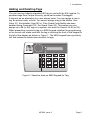
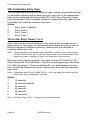
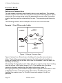
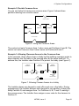
When presenting a proximity tag to a 9930 keypad, whether for programming
or for normal use, make sure that the tag is touching the front of the keypad to
the left of the display as shown in Figure 1. The 9940 keypad has a proximity
coil that makes the whole case sensitive to tags.
Figure 1. Sensitive Area on 9930 Keypad for Tag
497096, issue 3
Page 5
1. Introduction
To Add a Tag
1.
2.
Key in User 01 access code while the system is unset.
The display shows:
Press 4 to select the change codes option.
The display shows:
Select?
Old Code=
3.
Enter the access code of the user for whom you want to program a tag
and press y.
The display shows the user number and any text description you have
programmed for that user.
4.
Press y.
The display shows the user number and an underscore,
User 06 =
for example:
5.
_
_ _ _
Present the proximity tag to the front of the keypad (see Figure 1).
The system learns the identity of the tag and links it to that user number.
The keypad gives a double "beep" to confirm that the tag has been
learned successfully.
The keypad displays the date and time.
6.
Repeat steps 1 to 5 for other tags, as necessary.
To Delete a Tag
Note: If you delete a tag, you also delete that user's access code.
1.
2.
Key in User 01 access code while the system is unset.
The display shows:
Press 4 to select the change codes option.
The display shows:
Select?
Old Code=
3.
Enter the User 01 access code again and press y.
The display shows "User 01" and any text description for that user.
4.
Press X repeatedly until the display shows the user number of the tag
you want to delete.
The display shows the user number and any text you have programmed
for that user.
5.
6.
Press y.
Key in "0000" and press y.
The system deletes the tag and the user's access code. The keypad
gives a double "beep".
Page 6
497096, issue 3
_
2. PROGRAMMING COMMANDS
0: Country PTT Defaults
Use this command to select the country and PTT defaults; it also loads default
access codes and programming options. Use Command 126 to select
language without making other changes.
Note: If you select options X4, X5, X6 or X7 (Finland, Norway, Sweden or Denmark), the
control unit changes the method of entering installer mode (see "Entering Installer
Mode" on page 1).
Option
0
1
2
3
4
5
UK (default)
Italy
Spain
Portugal
Netherlands
France
Option
6
7
8
9
X1
X2
Belgium
Germany
Switzerland
Austria
Ireland
OEM 1
Option
X3
X4
X5
X6
X7
OEM 2
Finland
Norway
Denmark
Sweden
01 to 16, X17 to X40: Zone Programming
The number of zones available to program depends on the control unit model
and the number of expanders in your system (for details, refer to the 9x5x
Installation Guide). The format of the zone programming command changes,
depending whether a zone is connected to the control unit or to an expander.
For the first 16 zones, which are connected to the control unit, key in "01" to
"16" and press y. For zones 17 upwards, which are connected to expanders,
key in "X17" to "X40" (if that many zones are connected) and press y.
The zone programming commands take at least three further digits: the first
two specify the zone's type, while the others specify the zone's attributes.
When you key in the zone number and press y, the display shows the zone
number and any text associated with it. At this point, you can edit the zone
text. When the text is as required, press y to display the zone type and
attributes. At this point, you can edit them. When they are as required, press
y once more to store the changes.
Zone Names
When you key in the zone number and press y, the display shows the current
zone name with a flashing cursor under the first letter. Zone names can
contain up to 12 characters, including spaces and punctuation marks.
497096, issue 3
Page 7
2. Programming Commands
Enter letters from the keypad one at a time by repeatedly pressing a number
key until the display shows the letter you want. If you make a mistake, press C
or D to move the cursor to the letter you want to change and key in the new
letter. To delete a name completely, press D to move the cursor onto the first
character of the name and then press D again to clear the old name.
When you have finished entering the name, press y.
The following table shows the letters generated by each key on the keypad.
1
2
3
4
5
6
ABCÆÅÄ
DEF
GHI
JKL
MNOØÖ
7
8
9
0
C
D
PQRS
TUV
WXYZ
Space ' ( ) : . - ! &
Move right
Move left
Zone Types
The following table shows the values available for zone type.
Value
00
Type
Not Used
(NU)
01
Panic Alarm
(PA)
02
Fire (FR)
03
Normal Alarm
(NA)
24-hour (24)
04
Page 8
Description
Identifies zones that are not used. The system ignores zones of
this type. It is not necessary to link the circuit or anti-tamper
connections.
Operating a device programmed as "Panic Alarm" will start
either a silent alarm transmission to the Alarm Receiving Centre
(ARC) or an audible alarm, depending on how you have
programmed PA Response (see Command 30). PAs operate,
whether the system is set or unset. PA zones can be allocated
to one or more partitions in a partitioned system (A–D attributes
on page 12) but these attributes are not available in a single
system.
Smoke or heat detectors connected to FR type zones cause the
speakers to give a distinctive fire signal (internal sounders
pulsing "Dee Dah Dee Dah..."). Fire alarms always operate,
whether the system is set or unset, and always trigger
communications if fitted. Fire zones can be allocated to one or
more partitions in a partitioned system (A–D attributes on page
12) but these attributes are not available in a single system.
A zone programmed as "Normal Alarm" will start an alarm if
activated while the system is set.
This zone causes an internal alarm if violated when the system
is unset, and a full alarm if the system is set. If the Installer
programs 24-hour zones with "Omit Allow", the user can omit
24-hour zones in Day mode. The control unit reinstates all 24hour zones if anyone sets the system.
497096, issue 3
2. Programming Commands
Value
05
06
07
08
09
10
Type
Description
Final Exit (FE) Zones of this type must be the first to be activated on entry. You
can use them to set the system using the Final Door Set exit
mode. Use Command 39 to set the exit mode for the zone (page
20). Use zone attribute X7 to select an entry timer for the zone
(page 12) and Commands 201–4 (page 66) to set up the entry
timers.
Entry Route
Use this zone type for detectors sited between the Final Exit
(ER)
door/detector and a keypad. If an "Entry Route" zone is violated
when the system is set, an alarm will occur. If the Entry/Exit
timer is running when an Entry Route zone is violated, no alarm
occurs until the Entry/Exit timer expires. Use zone attribute X7 to
select an entry timer for the zone (page 12) and Commands
201–4 (page 66) to set up the entry timers.
Shock
You can apply this zone type to zones 1 to 4. The system will
Analyser (SA) not accept this type for zones 5 to 40. Use zone attribute X7 to
set the sensitivity for the zone (page 12).
Technical
Use this zone type when you want to monitor equipment, for
Alarm (TC)
example a freezer, without raising a full alarm. If a Technical
Alarm zone is activated while the system is set, the system
makes no audible alarm. However, when a user unsets the
system, the keypad indicates a fault. If a Technical Alarm zone
is activated while the system is unset, the system starts a pulsed
tone from the keypad. If programmed, the control unit also starts
communication. When a user enters a valid code, the keypad
stops the tone and displays the zone.
Keybox (KB)
This zone type is for use in Scandinavia only. When a zone of
this type is required, the Installer connects the alarm wires of the
zone to a special external key box and the tamper wires to the
box enclosure switch. When someone opens the box, the
control unit logs the event and communicates it to the Alarm
Receiving Centre (ARC). The control unit also provides a Key
Box output type, which you can program with Command 151 to
trigger one of the plug-by communicator output pins.
Smoke
In Scandinavia only, use this type for zones connected to 12V
Detector (SD) smoke detectors. This type is active whether the system is set or
unset, and the control unit will transmit a specific alarm to the
Alarm Receiving Centre (ARC) if triggered. The control unit also
provides a Smoke Detector output type, which you can program
with Command 151 to trigger one of the plug-by communicator
outputs. If a zone of this type causes an alarm, the user will
need to enter an access code to disarm and reset the system.
497096, issue 3
Page 9
2. Programming Commands
Value
11/12
Type
Keyswitch
13
Anti-Mask
Zone (AM)
14
Forbikobler
(FB)
15
AC Fail (AC)
16
Low Battery
(LB)
Page 10
Description
There are two Keyswitch zone types: Momentary and Fixed.
Use these for zones that connect to an access control keypad,
electronic key or other hardwired device used to set or unset the
system:
11
Momentary Keyswitch (KM)
12
Fixed (or latched) Keyswitch (KF)
The keyswitch or similar device can be used to set and unset
the level or partition to which the zone is assigned. It cannot be
used to reset the system.
In a single system, do not assign a Keyswitch zone to levels B,
C or D if you have assigned one to Level A (full system). In a
partitioned system, do not assign more than one Fixed
Keyswitch zone to a partition.
Note: In a partitioned system with a keyswitch for each partition,
operating a second keyswitch whilst the first partition is starting
to set will prevent the second partition from setting.
Use this zone type for the anti-mask outputs of detectors with
this facility. Connect the detector's alarm and contact wiring to
one zone (for example, Zone 07) and its anti-mask outputs to
the zone above (for example, Zone 08). Assign the Anti-Mask
type to the higher zone; that is, the one connected to the antimask outputs (Zone 08 in the example).
If an Anti-Mask zone is violated, the control unit starts a Tamper
Alarm and shows the message "AM Tamper" on the keypad
display. It logs the event to the zone connected to the detector's
alarm and contact wiring (Zone 07 in the example). Command
136 defines whether an Anti-Mask zone can be reset by a user
or only by the installer.
To use two-zone anti-masking, Command 88 must be set to 0
(Mask only).
This zone type is a Scandinavian type of Entry/Exit zone (the
word "forbikobler" means "bypass" in Danish). Use this type for
zones connected to standalone external keypads or access
controllers. If the zone is triggered by the external keypad during
the exit time, the control unit stops the exit time and sets the
system. If the zone is triggered while the system is set, the
control unit starts the entry time. Use zone attribute X7 to select
an entry timer for the zone (page 12) and Commands 201–4
(page 66) to set up the entry timers.
This zone type is triggered by a failure in the AC input to an
external power supply. Command 134 defines whether a zone of
this type can be reset by a user or only by the installer.
Command 137 defines whether the user can override the fault to
set the system. In a partitioned system, AC zones are always
allocated to Partition A.
This zone type is triggered by a low voltage in the battery in the
external power supply. In a partitioned system, LB zones are
always allocated to Partition A.
497096, issue 3
2. Programming Commands
Value
17
Type
Battery Fault
(BF)
18
Power Output
Failure (PF)
19
Fault (FL)
Description
This zone type is triggered by a fault in the battery in the
external power supply. In a partitioned system, BF zones are
always allocated to Partition A.
This zone type is triggered by a failure in the DC output to the
external power supply. In a partitioned system, PF zones are
always allocated to Partition A.
This zone type triggers a fault condition, causing an alert and
preventing the system from being set. The tamper connection
operates in the same way as a normal alarm zone (type "NA").
Command 139 defines whether a zone of this type can be reset
by a user or only by the installer. Command 140 defines whether
the user can override the fault to set the system. In a partitioned
system, FL zones are always allocated to Partition A.
Zone Attributes
The following table shows the values available for zone attribute, depending
on the zone type. To set an attribute, key in the appropriate value. To unset
the attribute, key in the value again.
Value
Attribute
Valid for
Description
X1
Chime (C)
Normal Alarm
(NA)
Final Exit (FE)
Entry Route
(ER)
Shock Analyser
(SA)
X2
Soak Test (S)
Normal Alarm
(NA)
Entry Route
(ER)
24-hour (24)
Shock Analyser
(SA)
When enabled by the user, the system makes
a doorbell-like sound when any zones
programmed as "Chime" are opened. This
facility operates only while the system is
unset.
To make the Chime available from keypad
sounders but not internal sounders, use
Command 22 with option 0.
Use this zone attribute if you want to place on
long-term test a detector that you suspect is
giving false alarms. Zones with this attribute
are disabled for 14 days after you return the
control unit to user mode. If the zone is
opened while the system is set (or at any time
for a 24-hour zone), the control unit logs the
event as a "Soak Fail Znn" (nn = zone
number) without sounding any bells or starting
signalling. The control unit returns the zone to
normal use after 14 days, even if the system
is set at the time.
497096, issue 3
Page 11
2. Programming Commands
Value
Attribute
Valid for
X3
Double Knock
(D)
Normal Alarm
(NA)
Entry Route
(ER)
X4
X7
A
B
C
D
Page 12
Description
For zones with this attribute, no action is
taken on first activation. To cause an alarm,
the zone must be activated twice within a fiveminute period or remain open for longer than
10 seconds. An alarm will also occur if
another double-knock zone in any partition is
activated within five minutes of the first.
Programming a zone as "Double Knock" is a
way of reducing false alarms caused by
environmental changes but is not normally
recommended. Do not apply "Double Knock"
to radio zones with a PIR detector. The radio
PIR detector uses a lockout timer and will not
send a second activation within the Double
Knock period.
Omit Allowed
All
When applied to a zone, this attribute allows
(O)
the user to omit the zone when setting the
alarm. Do not allow the user to omit PA
zones.
Do not apply this attribute to an FE zone if
there is no ER zone present.
The meaning of this attribute depends on the zone type:
Shock Analyser You can set this attribute only for a zone of
Shock
(SA)
type SA, and only zones 1, 2, 3 and 4 support
Analyser
Sensitivity
this type. To set the sensitivity of a shock
sensor zone, enter a digit in the range 1 (least
sensitive) to 6 (most sensitive). You must
enter the whole sequence; for example, to set
the sensitivity to 3, press X73
To select which of the four entry timers (set
Entry Timer
Final Exit (FE)
up using Commands 201–4, as described on
Number
Entry Route
page 66) are used for the zone, enter a digit
(ER)
in the range 1 to 4. You must enter the whole
Forbikobler
sequence; for example, to select Entry Timer
(FB)
3, press X73
Armed in
All
When applied, the zone is armed when the
Level or
user selects Level or Partition A.
Partition A
Armed in
All
When applied, the zone is armed when the
Level or
user selects Level or Partition B.
Partition B
Armed in
All
When applied, the zone is armed when the
Level or
user selects Level or Partition C.
Partition C
Armed in
All
When applied, the zone is armed when the
Level or
user selects Level or Partition D.
Partition D
497096, issue 3
2. Programming Commands
For information on how zones behave in linked partitions, refer to "Common
Areas" on page 78.
Zones and Partitions
In a partitioned system, you can assign some zone types to two or more
partitions, and some zone types to one partition only.
One partition only
Panic Alarm (PA)
Fire (FR)
24-hour (24)
Technical (TC)
Smoke Detector (SD)
Keyswitch – Momentary (KM)
Keyswitch – Fixed (KF)
More than one partition
Normal Alarm (NA)
Final Exit (FE)
Entry Route (ER)
Shock Analyser (SA)
Keybox (KB)
Anti-Mask (AM)
Forbikobler (FB)
Use those zone types that can be assigned to more than one partition to
create a common area (see page 78).
Some zone types are not assigned to a partition: AC Fail (AC), Low Battery
(LB), Battery Fault (BF) and Power Output Fault (PF). The Fault zone type
(FL) is always assigned to Partition A.
20: Change Engineer Code
Note: 9x5x control units support six-digit access codes as well as the standard four-digit
codes. Command 56 sets the code length.
To change the Engineer Code:
1. Make sure you are in installer mode.
2. Press 20y
The display shows:
3.
Key in a new Engineer Code.
The display shows:
20:Code
20:Code
xxxx
4.
Press y
If Guard Code is enabled (Command 181), the display shows: 20:Guard
3.
Key in a new Guard Code.
The display shows:
4.
20:Guard
xxxx
Press y
497096, issue 3
Page 13
2. Programming Commands
21: Zone Configuration
This command enables you to select the wiring type of the zone connectors
on the control unit PCB. The default is option 0 for all models.
Zones type on 9751/2 PCB
0
Up to 8 closed circuit loop zones (CC + Com A/T).
1
Up to 8 fully-supervised loop zones (FSL 2K2/4K7).
Zones type on 9853 PCB
0
Up to 8 closed circuit loop zones (CC 4 wire).
1
Up to 8 end-of-line zones (EOL 2K2).
2
Up to 16 fully-supervised loop zones (FSL 2K2/4K7). This setting
enables up to 24 zones to be connected to expanders.
3
Up to 8 fully-supervised loop zones (FSL + EXP). This setting enables
up to 32 zones to be connected to expanders.
Note:
1.
Compliance with PD 6662 / prEN 50131-1: 2004 (see page 85) at Grade 3 (9853
units only) requires that Command 21 is set to one of the Fully Supervised Loop
options (2 or 3).
2.
Using three-resistor anti-mask wiring (9853 units only) requires that Command 21 is
set to one of the Fully Supervised Loop options (2 or 3).
You can connect more zones using expanders. The maximum number of
zones depends on the type of control unit. Refer to the Installation Guide for
details.
22: Loudspeaker Chime
In a single system, a user may find that the Chime tone from the keypads is
not loud enough. If so, use this command to make the internal sounder give
the Chime tone as well. If you select option 0, the internal sounder emits no
tone. Select a value from 1 (quietest) to 9 (loudest) to set the Chime volume
(the default is 5). The internal sounder demonstrates the volume when you
enter the digit.
Note: In a partitioned system, this command is available only for Partition A.
Page 14
497096, issue 3
2. Programming Commands
23: Remote Reset Enable
Option 1 enables Remote Reset, which is designed to operate with the plugby communicator or remote PC reset. After an alarm, the user keys in an
access code to silence the alarm but cannot reset the system. The first alarm
message to display and the Service lamp remain visible. The user contacts
the Alarm Receiving Centre (ARC), which verifies the user's identity and then
sends a signal to the control unit. The Service lamp goes out and the user can
then reset the system with any valid access code, provided that there are no
faults.
Use option 0 (the default) to disable this function.
Notes:
1.
To ensure option 1 works correctly, you must set System Reset to Engineer
(Command 33 option 1) and set a CSID code (Command 50).
2.
To comply with PD 6662 / prEN 50131-1: 2004, the system must be set to hide
status information after 30 seconds (Command 28), in which case the Service lamp
will go out after the same period.
24: Show Control Unit Account Name
An account name can be programmed into a control unit using Downloader.
Use this command to display the account name.
25: Internal Sounder Delay and Duration
Option 0 (the default) makes the internal sounder use the external Bell Delay
and Duration times. Option 1 makes the internal sounder continue after the
external Bell Delay expires, stopping only when a user enters an access code.
26: Internal Sounder Delay on Entry
This command controls when internal sounders start to operate in response to
an intruder straying from the Entry Route or the entry time expiring.
If you select option 0, the control unit starts the internal sounders immediately.
If you select option 1 (the default), the control unit starts the internal sounders
at the same time as the external sounders (that is, after any Bell Delay). This
delay allows silent communications when an entry alarm is triggered, which is
required by some police forces. Option 1 is available only when:
° Alarm Abort is Off (Command 36, option 0)
° Bell Delay is not zero (Command 41, not option 0)
° Alarm Confirm is Off (Command 89, option 0)
Note: Compliance with PD 6662 / prEN 50131-1: 2004 (see page 85) at Grades 1, 2 and
3 requires that Command 26 is set to option 0.
497096, issue 3
Page 15
2. Programming Commands
27: Exit Fault External Sounder
This command controls what happens when an exit timer completes and a
zone is still violated (for example, when a door is not shut).
Option
0
Internal (default). System operates the internal sounders only.
1
Local. System operates both internal and external sounders.
Note: Compliance with PD 6662 / prEN 50131-1: 2004 (see page 85) prohibits an alarm
after a failure to set the system, which would require Command 27 to be set to
option 0. However, if external sounders are preferred, 9x5x control units also
provide "Set Fail" outputs that can be used to indicate that an alarm resulted from a
set failure.
28: Status Display
If you select option 0 (the default), the keypad displays "Level Set" or "Partn.
Set" continuously for the whole time that the alarm system is set. The keypad
lamps are illuminated if a relevant condition exists. Select option 1 to clear the
display and turn off the lamps 30 seconds after the user's last action.
The following table shows the effect of these settings in more detail.
Panel Set
No alerts
Alerts
Panel Unset
No alerts
Alerts
P/L
Text
0
1
continuous timed
P/L set
P/L set
30s, then
T&D
P/L set
P/L set
30s, then
T&D
1
0
continuous timed
T&D
T&D
T&D
T&D
Partition or level
Alert lamp
0
1
continuous timed
Off
Off
Service/Mains lamps
0
1
continuous timed
On
On* 30s
On
On 30s
On
On* 30s
0
continuous
Off
On
1
timed
Off
On
0
continuous
On
On
1
timed
On* 30s
On* 30s
T&D Time and date
*
If a relevant condition exists
Note: Compliance with PD 6662 / prEN 50131-1: 2004 (see page 85) at Grades 1, 2 and
3 requires that Command 28 is set to option 1.
Page 16
497096, issue 3
2. Programming Commands
29: Entry Alarm Delay Time
This command determines what the system does if a user strays from an
Entry Route zone during entry.
If you select option 0 (the default), the system gives an immediate alarm when
the user strays from an Entry Route zone during entry.
If you select option 1, the system gives an internal alarm when the user strays
from an Entry Route zone during entry but waits for 30 seconds before raising
a full alarm. The user can reset the system by entering an access code within
that time.
Note: Compliance with PD 6662 / prEN 50131-1: 2004 (see page 85) requires that
Command 29 is set to option 1.
30: PA Response
When a Panic Alarm (PA) occurs, the system sends a PA message to the
Alarm Receiving Centre (ARC), if a communicator is enabled, and the keypad
shows the PA zone when a user disarms the system. With this option, you
can choose whether the system also operates the sounders.
Option
0
Sounders operate (default).
1
Sounders remain quiet.
31: Zone Tamper User/Engineer Reset
Use this command to ensure that the system complies with national
requirements for resetting zone tamper indications while the system is unset.
If you select option 0 (the default), the user can reset the system after a zone
tamper.
If you select option 1, the user can silence the alarm after a zone tamper but
an engineer must reset the system by entering the Engineer Code, or by
using a remote or anti-code reset (Commands 23 and 50).
Note: See Commands 37 and 38 for reporting and resetting system tampers (for example,
attempts to open control unit or keypad cases).
32: Keypads and Partitions
If you created a partitioned system during initial power up, this command
enables you to assign individual keypads to those partitions. By default, all
keypads belong to all partitions.
Notes:
1.
You cannot assign keyswitches connected to keypads to partitions.
2.
PAs belong to the whole system.
3.
Command 66 is used to assign Forbikobler keypads to partitions.
497096, issue 3
Page 17
2. Programming Commands
33: System User/Engineer Reset
To require an engineer reset, select option 1. To permit a user reset, select
option 0 (the default). Certain types of events always need an engineer reset,
irrespective of the option that you choose here:
° Auxiliary 12V supply fuse blown
° Keypad missing or failed
° Remote expander missing or failed
° A low battery at the control unit.
Note: Compliance with DD 243: 2004 (see page 83) requires that Command 33 is set to
option 1. You can use various other forms of reset, such as remote (see Command
23) or anti-code (see Command 50).
34: PA User/Engineer Reset
To require an engineer to reset the system after a PA, select option 1. To
permit a user to reset the system after a PA, select option 0 (the default).
35: First Circuit Lockout
If you select option 0 (Lockout), the first zone to activate during the set cycle
is ignored until the system is unset. This is the default.
If you select option 1 (Rearm), all zones are included at the end of the
programmed bell run time, provided that the first-to-alarm zone is closed and
the number of rearms is not exceeded. While the zone is open, the system
excludes it. If the zone closes after the system rearms, the system includes it
again.
36: Alarm Abort
Users occasionally trigger false alarms by accident. Select option 1 to permit
them to abort under these circumstances.
If a user accidentally triggers an alarm while the system is set, the control unit
transmits an intruder alarm and starts the Bell Delay and Alarm Abort timers.
To abort the alarm, the user must enter a valid access code during the abort
period. If the user enters a valid code within this time, the system transmits a
restore of the intruder alarm and simultaneously transmits an abort.
Select option 0 (the default) to prevent users from aborting alarms in this way.
Note: The Alarm Abort period is controlled by the Alarm Receiving Centre (ARC).
Page 18
497096, issue 3
2. Programming Commands
37: Daytime Tamper Communication
This command defines how the control unit reports tamper indications (for
example, an attempt to open a control unit or keypad case) while the alarm
system is unset.
Option
0
Internal sounder only (default).
1
Internal sounder and communication of tamper indication to the Alarm
Receiving Centre (ARC).
Notes:
1.
Compliance with PD 6662 / prEN 50131-1: 2004 (see page 85) at Grade 3 requires
that Command 37 is set to 1 (see notes for Command 132 on page 53).
2.
Command 31 sets user/engineer reset for zone tampers.
3.
Command 38 sets user/engineer reset for system tampers.
4.
Command 58 sets user/engineer reset for system tampers.
38: System Tamper User/Engineer Reset
This command defines how to reset the control unit after a tamper alarm (for
example, an attempt to open a control unit or keypad case).
To require an engineer reset, select option 1 (the default). To permit a user
reset (provided that no tamper circuit is open), select option 0.
Note: This facility is independent of the options selected in Commands 31 and 33.
497096, issue 3
Page 19
2. Programming Commands
39: Level/Partition A Exit Mode
Use this command to select the exit mode for Full Set or Partition A. The
keypads give a double "beep" confirmation tone at the end of all setting
modes, including Silent Set. The default is option 0, Timed.
In a single system, the options are:
Option
0
Timed. Use this option if the system sets after an exit time selected
using Command 44. If an Exit Terminate button is fitted, the user may
use it to shorten the exit time.
1
Terminated. Use this option if the user completes setting the system
by pushing an Exit Terminate button connected to a keypad. The exit
time is infinite in this option. The system sets 7–12 seconds after the
completed action; the delay is set with Command 182 (see page 63).
2
Final Door Set. Use this option to complete setting of the system by
closing a door fitted with a Final Exit zone detector. The exit time is
infinite in this option. The system sets 7–12 seconds after the
completed action; the delay is set with Command 182 (see page 63).
3
Lock Set. To use this option, you must install a lock switch and
connect its contacts to the ET terminals of a keypad (refer to the 9x5x
Installation Guide). This facility is available on keypad software
version 1.4.2 onwards. See the notes below for more information.
In a partitioned system, the options are:
Option
0
Timed. Use this option if the system sets after an exit time selected
using Command 44. If an Exit Terminate button is fitted, the user may
use it to shorten the exit time.
1
Terminated. Use this option if the user completes setting the system
by pushing an Exit Terminate button connected to a keypad. The exit
time is infinite in this option. The system sets 7–12 seconds after the
completed action; the delay is set with Command 182.
2
Final Door Set. Use this option to complete setting of the system by
closing a door fitted with a Final Exit zone detector. The exit time is
infinite in this option. The system sets 7–12 seconds after the
completed action; the delay is set with Command 182.
3
Instant Set (no exit tone). Use this option to make the system set
without delay or exit tone.
4
Silent Set. Use this option to make the system set without an exit
tone. Use Command 44 to program the exit time.
5
Lock Set. To use this option, you must install a lock switch and
connect its contacts to the ET terminals of a keypad (refer to the 9x5x
Installation Guide). This facility is available on keypad software
version 1.4.2 onwards. See the notes below for more information.
Page 20
497096, issue 3
2. Programming Commands
Notes on Lock Set:
1.
Do not assign the keypad to more than one partition. Do not connect more than one
lock switch (or any other device) to the keypad ET terminals. In a single system, do
not attempt to fit two lock switches.
2.
To set the system, the user first enters their access code at a keypad or operates a
keyswitch. The control unit starts to emit the exit tone. The exit time is infinite in this
option. The user then operates the Final Exit zone and turns the key in the lock
switch to "locked". The system sets 7–12 seconds after the lock switch contacts
open; the delay is set with Command 182 (see page 63).
3.
To unset the system, the user turns the lock switch to "unlocked" (which closes the
contacts). The keypads start to emit a continuous tone; this is not affected by
PD6662 / pr EN 50131-1: 2004, as the possession of a key indicates an authorised
user. At this point, the user can lock the lock switch again without causing an alarm.
When the user opens the Final Exit zone, the control unit starts the entry timer. The
user completes entry by unsetting the system in the normal way.
4.
When the user unlocks the lock switch, the control unit disables Alarm
Confirmation. If the user locks the lock switch without starting the entry timer, the
control unit enables Alarm Confirmation again.
5.
If an intruder opens the Final Exit door without first unlocking the lock switch, the
control unit immediately starts an unconfirmed alarm. If the intruder goes on to
violate another zone and Alarm Confirmation is enabled, the control unit sends a
confirmed alarm.
40: System Auto Rearm
This command sets the number of times that the system will rearm all closed
zones when the bell duration expires. If you select option 0, the system will
not rearm (it will go into alarm only once). Select option 1 to rearm once, 2 to
rearm twice, 3 to rearm three times or 4 to rearm every time the bell duration
expires.
Use this command in conjunction with Command 35, First Circuit Lockout.
If the system has rearmed, the control unit gives an audible internal alarm
instead of the normal entry tone when a user enters the premises through the
Entry Route.
497096, issue 3
Page 21
2. Programming Commands
41: Bell Delay
When an alarm occurs (for example, an intruder violates a zone), the system
waits for the Bell Delay before operating the external sounder for the Bell
Duration. This command sets the Bell Delay.
Note: Compliance with PD 6662 / prEN 50131-1: 2004 (see page 85) requires that the
Bell Delay does not exceed 10 minutes and that it is not used for entry alarms (see
Command 26).
Option
0
No delay (default)
1
1.5 minutes
2
3 minutes
3
5 minutes
4
10 minutes
5
15 minutes
6
20 minutes
Note: Command 41 has no effect if Alarm Confirmation (Command 89) is enabled and any
of the following applies:
External Sounder (Command 162) is set to option 0
Internal Sounder (Command 161) is set to option 0
Alarm Response Mode (Commands 47, 63, 73 and 77) does not require
communications.
42: Bell Duration
When an alarm occurs (for example, an intruder violates a zone), the system
waits for the Bell Delay before operating the external sounder for the Bell
Duration. This command sets the Bell Duration.
Note: Compliance with PD 6662 / prEN 50131-1: 2004 (see page 85) requires that the
Bell Duration does not exceed 15 minutes.
Option
1
1.5 minutes
2
3 minutes
3
5 minutes
4
10 minutes
5
15 minutes (default)
6
20 minutes
43: Not used
Level A Entry Time has been replaced by Command 201–204.
Page 22
497096, issue 3
2. Programming Commands
44: Level/Partition A Exit Time
This command lets you set the Exit Time for Full Set or Partition A.
Option
1
10 seconds
2
20 seconds (default)
3
30 seconds
4
45 seconds
5
60 seconds
6
120 seconds
45: Entry/Exit Tone Volume
In a single system, this command sets the volume of the Entry/Exit tone from
the internal sounder. If you select option 0, the internal sounder emits no tone.
Select a value from 1 (quietest) to 9 (loudest) to set the volume (default 5).
The internal sounder demonstrates the volume when you enter the digit.
Note: In a partitioned system, this command is available only for Partition A.
46: Tamper Alarm Response
In a single system, this command specifies which sounders the control unit
will activate for a Tamper Alarm while the system is unset.
Option
0
Internal sounders only (default)
1
Keypad sounders only
2
Internal and keypad sounders
Note: This command is not available in a partitioned system.
47: Partition A Alarm Response
In a partitioned system, this command specifies which sounders the control
unit will activate for an alarm.
Note: Compliance with PD 6662 / prEN 50131-1: 2004 (see page 85) requires the full
response, option 2 (default).
Option
0
Keypad sounders only
1
Local alarm (internal and external sounders)
2
Full alarm (internal and external sounders, plus communication)
Note: This command is not available in a single system.
497096, issue 3
Page 23
2. Programming Commands
48: Lockout Keypads During Entry
This command enables you to lock keypads during entry when proximity tag
readers or remote setting devices are being used to unset the system. When
you lock keypads during entry, some functions are still available:
° Keypad PA, Fire and Medical alarms
° Duress Code operation
° User's ability to cancel false alarms or disarm the system during an alarm.
If you select option 0, the system permits all users to use all keypads during
entry. If you select option 1, it locks all users out of all keypads during entry.
The display shows 'abcd' for option 1 in a partitioned system to indicate that
locking affects all partitions; you cannot change the partitions affected.
Note: Compliance with DD 243: 2004 (see page 83) requires that Command 48 is set to
option 1 when using portable ancillary control equipment to unset the system with
readers inside the premises (section 6.4.5). Otherwise (sections 6.4.2, 6.4.3, 6.4.4
and 6.4.6), set this command to Option 0.
49: Duress Code
This command selects whether the control unit supports a Duress Code (set
by the master user as described in the 9x5x User Guide). Entering this code
will cause a silent communication to be sent to the Alarm Receiving Centre
(ARC) if a user is forced to unset the system by an intruder.
A duress restore is communicated on the first occasion that a normal user
access code is entered after the duress code has been used.
Option
0
Off (default). No Duress Code.
1
On. Duress Code.
Note: If the duress code is disabled and then enabled again, the code previously
assigned to it by the user will be lost. A new duress code must be assigned.
Page 24
497096, issue 3
2. Programming Commands
50: CSID Code
To enable the user to use the "Remote Reset" facility (enabled with Command
23), you must program the control unit as "Engineer Reset" (Command 33
option 1) and install a four-digit Central Station Identification (CSID) code:
1. Contact the Alarm Receiving Centre (ARC) and obtain the CSID code.
2. Ensure that the system is in installer mode.
3. Select Command 50 and enter the four-digit CSID code.
The control unit now contains the same CSID code as the ARC and can use
this to generate a four-digit reset code that will be recognised by the ARC
7300 Remote Reset decode programmer.
After an alarm, the user keys in their access code to silence the alarm but
cannot reset the system. The system generates the reset code and displays it
on the keypad. The user calls the ARC and reports the reset code. The ARC
verifies the user's identity and then enters the reset code into the 7300
programmer, which generates an anti-code. The ARC gives the anti-code to
the user, who keys it into the keypad to reset the system.
Note: To delete a CSID code, key in "0000" over the existing code.
51: Set Time and Date
The system has an internal clock/calendar, which it uses to record the time
and date of events in the log. This command sets the current time and date in
the clock/calendar. The system displays the date first: enter the day, month
and year in turn, each as two digits. The system then displays the time: enter
the hours and minutes in turn, each as two digits (using the 24-hour clock).
52: Omit Alarm
This command specifies whether, when a user omits a zone, the control unit
omits the tamper contacts as well as the alarm contacts.
Option
0
The control unit omits alarm contacts only.
1
The control unit omits both alarm and tamper contacts.
Note: To permit the user to omit a zone, you must set attribute X4 for the zone.
53: Abort User/Engineer Reset
This command specifies how the system is reset after an aborted alarm.
Option
0
Use the reset option selected for the system with Command 33
(default).
1
Permit the user to reset after an abort.
497096, issue 3
Page 25
2. Programming Commands
54: Supervision Time
Radio zones are supervised. If they do not communicate for a certain time,
the control unit reacts in the way selected with Command 55. The time is
based on the supervision period of the radio detector used in the zone, which
depends on the model as shown in the following table. The model number is
usually shown on a label affixed to the PCB inside the detector.
Long period (29 minutes)
1715REUR-00
715REUR-00
715RUK-00
719REUR-00
735REUR-00
Short period (4 minutes)
1715REUR-02
715RB-00
715REUR-02
715REUR-01
719RB-00
719REUR-02
719REUR-01
735RB-00
735REUR-02
735REUR-03
735REUR-01
RST15RDK-00
RST19RDK-00
RST35RDK-00
all 734R models
735REUR-50
all 714R models
all 738R models
all 739R models
all 7525R models
Command 54 specifies whether the control unit uses slow or fast supervision,
which determines how quickly it reacts to losing contact with a radio zone. It
will never take more than two hours to react to a supervision failure.
Option
0
Supervision time slow.
1
Supervision time fast (default).
If the system uses any radio detectors with long supervision periods, select
option 0.
If the system uses only radio detectors with short supervision periods, you
can select either option. However, selecting option 1 will cause the control unit
to react to a loss of contact after only about 15 minutes.
Note:
1.
Compliance with PD 6662 / prEN 50131-1: 2004 Grades 1 and 2 (see page 85)
requires option 1.
2.
PD 6662 / prEN 50131-1: 2004 Grade 3 does not permit radio zones.
Page 26
497096, issue 3
2. Programming Commands
55: Supervision Response
This command specifies how the control unit responds to a reported
supervision failure (as described in Command 54).
Option
0
Supervision response: tamper (default)
1
Supervision response: alarm
2
Supervision response: fault
3
Supervision response: silent
Note: Compliance with PD 6662 / prEN 50131-1: 2004 Grades 1 and 2 (see page 85)
requires option 0. Grade 3 does not permit radio zones.
The response depends on whether the system is set or unset, as well as on
the option selected. The following table shows the possible variations.
Panel UNSET
Option
Lights Alert
lamp
Emits fault tone
Starts internal
sounder
Starts external
sounder
Sends to ARC
(EN 50131-1)
Sends to ARC
(other)
Records in
event log
Panel SET
Option
Lights Alert
lamp
Emits fault tone
Starts internal
sounder
Starts external
sounder
Sends to ARC
(EN 50131-1)
Sends to ARC
(other)
Records in
event log
0
Yes
1
Yes
2
Yes
3
Yes
Yes
Yes
Yes
No
Yes
No
No
No
No
No
No
No
Tamper
None
None
None
Supervision
Fault
Supervision
Fault + Tamper
None
None
None
Supervision
Fault
Supervision
Fault
Supervision
Fault
0
No
1
No
2
No
3
No
No
Yes
No
Yes
No
No
No
No
Yes
Yes
No
No
Tamper
Alarm
Supervision
Fault
Supervision
Fault + Tamper
Supervision
Fault
Supervision
Fault + Alarm
Supervision
Fault
None
Supervision
Fault
None
Supervision
Fault
Supervision
Fault
497096, issue 3
Page 27
2. Programming Commands
56: Number of Digits in Access Codes
The control unit can use either four-digit or six-digit access codes. Select
option 0 for four-digit access codes and option 1 for six-digit access codes.
Changing code length causes the system to revert to factory defaults for all
access codes; four-digit defaults are 1234 (user) and 7890 (engineer), sixdigit defaults are 123456 (user) and 567890 (engineer).
Note: Compliance with PD 6662 / prEN 50131-1: 2004 Grades 2 and 3 (see page 85)
require option 1; this applies even if you are using proximity tags because the
installer and master user will still use access codes. Grade 1 permits either option.
57: Battery Load Test (not 9751)
This command specifies whether the control unit should load test its backup
battery. If the battery fails a test, the control unit reports the failure to the
central station; it also emits a regular short tone through the keypad sounders
and shows the message "Batt Load Fail" on the keypad display.
Option
0
Do not load test the battery (default).
1
Load test the battery when the system is unset or 23 hours after the
last battery test (whichever comes first).
Note: Compliance with PD 6662 / prEN 50131-1: 2004 Grade 3 (see page 85) requires
option 1. Grades 1 and 2 permit either option.
58: Day Tamper User/Engineer Reset (not 9751)
To require an engineer to reset a tamper indication while the system is unset,
select option 1. To permit a user to reset a tamper indication in this situation,
select option 0 (the default). Irrespective of this setting, the user can continue
to set and unset the system while a tamper indication is being displayed.
Notes:
1.
Command 58 was originally used to achieve BVVO compliance.
2.
Use Command 38 to allow a user reset after a system tamper alarm.
59: External Sounder Tamper
This command specifies which one of two tamper arrangements is used to
connect the control unit to the external sounders. Select the appropriate
option for the sounder fitted to the system.
Option
0
Tamper return uses negative voltage (default).
1
Tamper return is terminated with a 2k2 resistance.
Page 28
497096, issue 3
2. Programming Commands
60: Level B Final Exit Operation
In a single system, this command specifies how the system treats Final Exit
zones during part set B. If you select option 0 (the default), Final Exit zones
included in Level B continue to act as Final Exit zones during part set B. If you
select option 1, these zones act as Normal Alarm zones during part set B.
Note: This command is not available in a partitioned system.
61: Level B Entry Route Operation
In a single system, this command specifies how the system treats Entry Route
zones during part set B. If you select option 0 (the default), Entry Route zones
included in Level B continue to act as Entry Routes during part set B. If you
select option 1, these zones act as Final Exit zones during part set B.
Note: This command is not available in a partitioned system.
62: Level/Partition B Exit Mode
This command sets the exit mode for Level or Partition B. The keypads give a
double "beep" confirmation tone at the end of all setting modes, including
Silent Set. The default is option 0, Timed.
In a single system, the options are:
Option
0
Timed. The keypad sounders and any internal sounders give a low
tone during exit of Level B. Use Command 65 to select the exit time.
1
Instant Set (no exit tone). Use this option to make the system set
without delay or exit tone.
2
Silent Set. Use this option to make the system set without an exit
tone. Use Command 65 to program the exit time.
3
Makes the Level B exit mode the same as Level A.
497096, issue 3
Page 29
2. Programming Commands
In a partitioned system, the options are:
Option
0
Timed. Use this option if Partition B sets after an exit time selected
using Command 65. If an Exit Terminate button is fitted, the user may
use it to shorten the exit time.
1
Terminate. Use this option if the user completes setting the partition
by pushing an Exit Terminate button connected to a keypad. The exit
time is infinite in this option.
2
Final Door Set. Use this option to complete setting the partition by
closing a door fitted with a Final Exit zone detector. The exit time is
infinite in this option.
3
Instant Set (no exit tone). Use this option to make the system set
without delay or exit tone.
4
Silent Set. Use this option to make the system set without an exit
tone. Use Command 65 to program the exit time.
5
Lock Set. See Command 39 on page 20 for an explanation.
63: Level/Partition B Alarm Response
This command sets the alarm response for Level or Partition B.
In a single system, the options are:
Option
0
Keypad sounders only.
1
Internal sounders and keypad sounders (default).
2
Local alarm (internal and external sounder only).
3
Full alarm (communication and internal/external sounders).
In a partitioned system, the options are:
Option
0
Keypad sounders only.
1
Local alarm (internal and external sounder only).
2
Full alarm (communication and internal/external sounders) (default).
Note: Compliance with PD 6662 / prEN 50131-1: 2004 (see page 85) requires that
Command 63 is set to option 2 in a partitioned system.
64: Not used
Level B Entry Time has been replaced by Command 201–204.
Page 30
497096, issue 3
2. Programming Commands
65: Level/Partition B Exit Time
This command sets the Exit Time for Level or Partition B.
Option
1
10 seconds
2
20 seconds (default)
3
30 seconds
4
45 seconds
5
60 seconds
6
120 seconds
66: Forbikobler Keypads and Partitions
If you created a partitioned system during initial power up, this command
enables you to assign individual Forbikobler keypads to those partitions. By
default, all Forbikobler keypads belong to all partitions.
Note: Command 32 is used to assign ordinary keypads to partitions.
67: Forbikobler Approved
This command specifies whether the Forbikobler system should operate in an
approved manner (user codes only) or a non-approved manner (proximity
tags and user codes).
Option
0
Non-approved
1
Approved (default)
68: Forbikobler Door Timer
This command sets the time that the Forbikobler system allows for entry to
the building (not the time needed to unset the system). During this period, an
optional output is activated to operate an electromechanical lock on the door.
Option
0
1
2
3
4
2 seconds
3 seconds
4 seconds
5 seconds (default)
10 seconds
5
6
7
8
9
20 seconds
30 seconds
60 seconds
120 seconds
255 seconds
497096, issue 3
Page 31
2. Programming Commands
69: Forbikobler Door Locking
This command specifies whether the door controlled by the Forbikobler
system is normally unlocked while the system is reset or opened only for a
controlled time. Even if the door is normally unlocked, it can be locked with a
user command if required.
Option
0
Lock Timed (default)
1
Lock Toggled
70: Level C Final Exit Operation
In a single system, this command specifies how the system treats Final Exit
zones during part set C. If you select option 0 (the default), any Final Exit
zones in Level C continue to act as Final Exit zones during part set C. If you
select option 1, these zones act as Normal Alarm zones during part set C.
Note: This command is not available in a partitioned system.
71: Level C Entry Route Operation
In a single system, this command specifies how the system treats Entry Route
zones during part set C. If you select option 0 (the default), any Entry Route
zones in Level C continue to act as Entry Routes during part set C. If you
select option 1, these zones act as Final Exit zones during part set C.
Note: This command is not available in a partitioned system.
72: Level/Partition C Exit Mode
This command sets the Exit Mode for Level or Partition C. The keypads give a
double "beep" confirmation tone at the end of all setting modes, including
Silent Set. The default is option 0, Timed.
In a single system, the options are:
Option
0
Timed. The keypad sounders and any internal sounders give a low
tone during exit of Level C. Use Command 75 to select the exit time.
1
Instant Set (no exit tone). Use this option to make the system set
without delay or exit tone.
2
Silent Set. Use this option to make the system set without an exit
tone. Use Command 75 to program the exit time.
3
Makes the Level C exit mode the same as Level A.
Page 32
497096, issue 3
2. Programming Commands
In a partitioned system, the options are:
Option
0
Timed. Use this option if Partition C sets after an exit time selected
using Command 75. If an Exit Terminate button is fitted, the user may
use it to shorten the exit time.
1
Terminate. Use this option if the user completes setting the partition
by pushing an Exit Terminate button connected to a keypad. The exit
time is infinite in this option.
2
Final Door Set. Use this option to complete setting the partition by
closing a door fitted with a Final Exit zone detector. The exit time is
infinite in this option.
3
Instant Set (no exit tone). Use this option to make the system set
without delay or exit tone.
4
Silent Set. Use this option to make the system set without an exit
tone. Use Command 75 to program the exit time.
5
Lock Set. See Command 39 on page 20 for an explanation.
73: Level/Partition C Alarm Response
This command sets the Alarm Response for Level or Partition C.
In a single system, the options are:
Option
0
Keypad sounders only.
1
Internal sounders and keypad sounders (default).
2
Local alarm (internal and external sounder only).
3
Full alarm (communication and internal/external sounders).
In a partitioned system, the options are:
Option
0
Keypad sounders only.
1
Local alarm (internal and external sounder only).
2
Full alarm (communication and internal/external sounders) (default).
Note: Compliance with PD 6662 / prEN 50131-1: 2004 (see page 85) requires that
Command 73 is set to option 2 in a partitioned system.
74: Not used
Level C Entry Time has been replaced by Command 201–204.
497096, issue 3
Page 33
2. Programming Commands
75: Level/Partition C Exit Time
This command sets the Exit Time for Level or Partition C.
Option
1
10 seconds
2
20 seconds (default)
3
30 seconds
4
45 seconds
5
60 seconds
6
120 seconds
76: Level/Partition D Exit Mode
This command sets the Exit Mode for Level or Partition D. The keypads give a
double "beep" confirmation tone at the end of all setting modes, including
Silent Set. The default is option 0, Timed.
In a single system, the options are:
Option
0
Timed. The keypad sounders and any internal sounders give a low
tone during exit of Level D. Use Command 79 to select the exit time.
1
Instant Set (no exit tone). Use this option to make the system set
without delay or exit tone.
2
Silent Set. Use this option to make the system set without an exit
tone. Use Command 79 to program the exit time.
3
Makes the Level D exit mode the same as Level A.
In a partitioned system, the options are:
Option
0
Timed. Use this option if Partition D sets after an exit time selected
using Command 79. If an Exit Terminate button is fitted, the user may
use it to shorten the exit time.
1
Terminate. Use this option if the user completes setting the partition
by pushing an Exit Terminate button connected to a keypad. The exit
time is infinite in this option.
2
Final Door Set. Use this option to complete setting the partition by
closing a door fitted with a Final Exit zone detector. The exit time is
infinite in this option.
3
Instant Set (no exit tone). Use this option to make the system set
without delay or exit tone.
4
Silent Set. Use this option to make the system set without an exit
tone. Use Command 79 to program the exit time.
5
Lock Set. See Command 39 on page 20 for an explanation.
Page 34
497096, issue 3
2. Programming Commands
77: Level/Partition D Alarm Response
This command sets the Alarm Response for Level or Partition D.
In a single system, the options are:
Option
0
Keypad sounders only.
1
Internal sounders and keypad sounders (default).
2
Local alarm (internal and external sounder only).
3
Full alarm (communication and internal/external sounders).
In a partitioned system, the options are:
Option
0
Keypad sounders only.
1
Local alarm (internal and external sounder only).
2
Full alarm (communication and internal/external sounders) (default).
Note: Compliance with PD 6662 / prEN 50131-1: 2004 (see page 85) requires that
Command 77 is set to option 2 in a partitioned system.
78: Not used
Level D Entry Time has been replaced by Command 201–204.
79: Level/Partition D Exit Time
This command sets the Exit Time for Level or Partition D.
Option
1
10 seconds
2
20 seconds (default)
3
30 seconds
4
45 seconds
5
60 seconds
6
120 seconds
Note: In a single system, you cannot change the operation of Final Exit and Entry Route
zones assigned to Level D as you can with Levels B and C (see Commands 60, 61,
70 and 71). For this reason, Cooper Security recommends that you use Level D for
simple applications only.
80: Forbikobler Chime
This command links the bell push on the Forbikobler keypad to the Chime on
the system, so that pressing the bell operates the sounders.
Option
0
Off. Pressing the bell push does not operate the sounders (default).
1
On. Pressing the bell push operates the sounders.
497096, issue 3
Page 35
2. Programming Commands
81 to 84: Output n Type
These commands, along with Commands 215 to 218, select types for the
control unit's panel outputs. They take two digits to select the type (see below)
and have the following defaults:
Command Output
Control unit
Default outputs
81
1
All
00 Bell
82
2
All
08 Strobe
83
3
All
03 Set Latch
84
4
9853
04 Shock Sensor Reset
215
5
9853
15 Set Complete
216
6
9853
16 Unset Complete
217
7
9853
38 All Fault
218
8
9853
01 EE Follow
Notes:
1.
Commands 84 and 215-218 apply only to the 9853, as only it has more than three
outputs.
2.
The panel outputs can be tested using Command 91 (page 73).
Option
00
Bell: active during an alarm. Use Command 41 to set Bell Delay and
42 to set Bell Duration. In a partitioned system, this type is activated
when any partition is in alarm. If Alarm Confirmation (Command 89) is
enabled, use Command 162 to set whether the bell is sounded on the
first or confirmed alarm.
01
EE Follow: active when Entry or Exit Time starts and inactive when
the time expires or is terminated. The output can be used for a
separate Entry/Exit buzzer. It will not give a tone during part set if the
exit mode is silent set or instant set.
02
Armed Lamp: active continuously while the system is full or part set.
03
Set Latch: active when the system is set and inactive when the
system is unset or an alarm condition occurs. It is active for one
second when a reset is performed or the control unit leaves installer
mode. It is also active during Walk Tests.
04
Shock Reset: used to reset shock sensors (for example, the "Viper").
The output is triggered by the control unit at the start of the Exit Time
and remains active for five seconds.
Page 36
497096, issue 3
2. Programming Commands
05
Walk Test: active during both engineer and user Walk Tests and
during the time between silencing and resetting the system. It is used
on movement detectors that are able to switch off the Walk Test lamp
in any state other than a Walk Test.
06
Ready Lamp: active when the system is unset and if there are no
faults. It is inactive when the system is full or part set, during any
alarm or if a circuit fault prevents setting. It is also active when the
control unit is in installer mode.
07
24-hour Alarm: activated when a zone designated as 24-hour is
violated and deactivated when the system is disarmed.
08
Strobe: activated during an alarm and deactivated when the system is
disarmed.
09
Smoke Reset: designed to be connected to low-voltage smoke
detector reset terminals. It is active for 3 seconds when the system is
reset after an alarm.
10
Siren Test: activated when the user performs a sounder test.
11
Strobe Set A: active for 10 seconds after the system (or any partition)
is set. It can be used to operate the Strobe output to give a visual
indication that the system has completed setting.
12
Pulse Set 1: active for the time set by Command 170 when someone
sets the system (same as type 26).
13
Pulse Unset 1: active for the time set by Command 172 when
someone unsets the system and during a Fire alarm or PA (same as
type 30).
14
Alarm Confirm: active during a confirmed alarm.
15
Set Complete: active for 10 seconds after someone sets the system.
16
Unset Complete: active for 10 seconds after someone unsets the
system or disarms it after an alarm.
17
System Alarm: activated when the control unit raises a System Alarm.
In a partitioned system, the following options (18-25) are also available:
18
Bell Partition A: active when an alarm occurs in Partition A.
19
Bell Partition B: active when an alarm occurs in Partition B.
20
Bell Partition C: active when an alarm occurs in Partition C.
21
Bell Partition D: active when an alarm occurs in Partition D.
22
Strobe Set A: active for 10 seconds after Partition A is set.
23
Strobe Set B: active for 10 seconds after Partition B is set.
24
Strobe Set C: active for 10 seconds after Partition C is set.
25
Strobe Set D: active for 10 seconds after Partition D is set.
497096, issue 3
Page 37
2. Programming Commands
26
Pulse Set 1: active for time set by Command 170.
27
Pulse Set 2: active for time set by Command 170.
28
Pulse Set 3: active for time set by Command 170.
29
Pulse Set 4: active for time set by Command 170.
30
Pulse Unset 1: active for time set by Command 172.
31
Pulse Unset 2: active for time set by Command 172.
32
Pulse Unset 3: active for time set by Command 172.
33
Pulse Unset 4: active for time set by Command 172.
34
Fire: active during a Fire alarm.
35
PA: active during a PA.
36
Set Fail: active for 60 seconds from when a set command fails.
37
General Fault: active for all faults except AC Fail, Anti-Mask, Battery
Fault, Line Fault, Supervision Fail, Zone AC Fail, Zone Battery Fault
and Zone Low Battery.
38
All Fault: active for all faults (including AC Fail, Anti-Mask, Aux DC,
Battery Load Test Fail, Battery Missing, Comms Fail, Jamming,
Keypad Ident Fail, Line Fail, Low Battery, Plugby Fail, RF Low
Battery, Supervision Fail, Telecommand Low Battery, uCom Fail,
Zone AC Fail, Zone Battery Fault, Zone Fault, Zone Low Battery and
Zone Pwr O/P).
85: Burglar Communication Rearm
This command determines what happens to the "burg" communications output
(or channel) at the end of the bell run time.
Option
0
Latched (default). The output stays active until an engineer or user
resets the system.
1
Rearm. The system turns off the "burg" channel when the bell run time
has expired. Once the channel is inactive, the system is ready to
report any new alarm.
Note:
If Alarm Abort is enabled (Command 36, option 1), the "burg" channel restores if
the user unsets the system.
86: Not used
This command has been replaced by the changed Command 29.
Page 38
497096, issue 3
2. Programming Commands
87: Keypad Dual Key Alarms
This command enables users to raise an alarm by pressing two keys on the
keypad at the same time. Three types of alarms are available, each of which
can be enabled or disabled independently. The default is disabled (option 0).
Alarm type
PA
Medical
Fire
Key combination
1 and 3
4 and 6
7 and 9
Disable
0
0
0
Enable
1
1
1
Press A and B to scroll up and down through the types (PA, FI and MD).
Notes:
1.
Selecting option 1 also enables any PAs connected to 9928 keyswitch interfaces or
to 9940 keypads.
2.
Compliance with DD243: 2004, which relates to the ACPO Security Systems Policy
2004, requires that dual key PA is disabled (option 0).
88: Anti-Mask Mode (9853 only)
When using the three-resistor wiring method for anti-masking, the three
possible signals from a detector are interpreted in combination:
Event
None
Intrusion
Tamper
Fault
Masking
Alarm
N
Y
any
N
Y
Signal
Tamper
N
N
Y
N
N
Fault
N
N
any
Y
Y
This command determines whether a resistance value of 4.4kΩ (resulting
from a Fault signal alone) is reported as Mask or Fault. If the detectors with
anti-masking outputs in the system can report faults, select option 1; if they
cannot, select option 0. For information on three-resistor anti-mask wiring,
refer to the 9x5x Installation Guide.
All detectors with anti-masking outputs used in the system must work in the
same way (either all report faults or none report faults). If no detectors with
anti-masking outputs are fitted, this command has no effect.
497096, issue 3
Page 39
2. Programming Commands
Option
0
Masking (default). Resistance values of both 4.4kΩ and 9.1kΩ are
reported as Masking detected.
1
Masking and Fault. A resistance value of 4.4kΩ is reported as a Fault
and 9.1kΩ is reported as Masking detected.
Note:
1.
Using three-resistor anti-mask wiring requires that Command 21 is set to one of the
Fully Supervised Loop options (2 or 3).
2.
Compliance with PD 6662 / prEN 50131-1: 2004 Grade 3 (see page 85) requires
that detectors can report faults and that Command 88 is set to 1.
89: Alarm Confirmation
Use this command to select if alarms are confirmed and, if so, how this is
done. Your local Police Intruder Alarms Policy may require alarms to be
confirmed.
Option
0
None: alarm is communicated when one zone is activated (default
outside the UK).
1
UK (DD 243): alarm is not communicated until a second zone is
activated within 30 minutes of the first (default in the UK).
2
2Zn: alarm is communicated when any two zones are activated at any
time while the system is set.
Note:
1.
Compliance with DD 243: 2004 (see page 83) requires that Command 89 is set to
option 1.
2.
Activating entry zones during the entry time will not cause or confirm an alarm.
90: Event Log
For information on this command, see page 69.
91 to 96: Testing Outputs
For information on these commands, see page 73.
97: Engineer Walk Test
For information on this command, see page 73.
98: Load Full Defaults
This command loads the original default values for all commands and selects
single or partitioned operation (for more information, see page 4).
Page 40
497096, issue 3
2. Programming Commands
99: Leave Installer Mode
This command returns to user mode (for more information, see page 3).
100: Not used
This command is not used.
101: Call Mode
Use this command to select the call mode used by the communicator when
contacting the Alarm Receiving Centre (ARC).
Option
0
Disabled (default). The control unit does not use any communications.
1
Single reporting. The control unit reports to one programmed
telephone number (see Command 115) with one account number (see
Command 117).
Operation: The communicator dials the number and tries to connect
with the ARC. If it fails, it closes down and then tries again. It will try to
connect up to 15 times.
2
Alternate reporting. The control unit reports to one of two programmed
telephone numbers (see Commands 115 and 116), still using one
account number (see Command 117).
Operation: The communicator dials the first telephone number and
tries to connect to the ARC. If it fails, it closes down, dials the second
telephone number and tries to connect to the ARC again. If this
attempt is received and acknowledged, the system closes down and
the alarm transmission is complete. If this attempt fails, the system
closes down and tries again to connect to the first telephone number.
The communicator tries the two numbers in turn for up to 15 times,
until it has successfully called one of them.
3
Dual reporting. The control unit reports to two programmed telephone
numbers, one each for two receivers (see Commands 115 and 116).
Operation: The communicator dials the first telephone number and
tries to connect to the first ARC. If this attempt is received and
acknowledged, the communicator dials the second number and tries
to connect to the second ARC. If this attempt is received and
acknowledged, the communicator closes down and the alarm
transmission is complete. If the call to the first number fails, the
communicator tries the second number. If the call to the second
number fails, the communicator closes down and tries the first number
again. The communicator tries the two numbers in turn for up to 15
times, until it has successfully called both of them.
Note: Dual reporting does not work with SIA or CID reporting formats.
497096, issue 3
Page 41
2. Programming Commands
102: Communication Fault Timeout
This command sets the period after which a communications fault times out.
In earlier versions of the 9x5x series, timeouts occurred after a specified
number of calls.
Option
0
60 seconds
1
120 seconds
2
240 seconds (default)
3
480 seconds
Note: Compliance with PD 6662 / prEN 50131-1: 2004 (see page 85) requires that
Command 102 is set to option 2.
103: Reporting Type
The system supports several message formats for communications:
Option
0
Scancom Fast Format (FF) (default)
1
Contact ID (CID)
2
Scancom SIA Level I (SIAI)
3
Scancom SIA Level II (SIAII) – this does not send time and date
4
Scancom SIA Level 3 (SIA3)
5
Extended Scancom SIA Level 3 (XSIA3)
6
Home "beep" (Home)
Option 6, Home "beep", is not a particular message format. What it means is
that the communicator dials a number and sends a "beep" down the line. This
does not allow a complex message to be sent but means that the person
answering the call needs no special equipment to decode the message. The
number of times the communicator repeats the Home "beep" is set with
Command 186. For the 9853 only, the receiver can press 5 on the telephone
keypad to acknowledge the alarm and terminate the series of calls.
104: Not used
This command is not used.
Page 42
497096, issue 3
2. Programming Commands
105: Static Test Call
With static testing, the control unit makes test calls at fixed times or intervals;
alternatively, you can use Command 108 (see page 44) to set up a dynamic
test call for 24 hours after the last communication.
Note: Cooper Security recommends that you choose either Static Test Call (105) or
Dynamic Test Call (108), but not both at the same time.
To disable static test calls, key in "00".
To make static test calls at a regular time, you have two options:
Ann To make a static test call at a set time every day, press A and then key in
a number between 01 and 24 to select the time for the call. For example,
key in "18" to program the control unit to make a call at 6.00pm every
day.
Bnn To make a static test call on a set day of every month, press B and then
key in a number between 01 and 28 to select the day for the call. For
example, key in "22" to program the control unit to make a call on the
22nd day of every month. The call will be made at 1.00am.
To make static test call at regular intervals, you have two options:
Cnn To make a static test call every nn hours, press C and then key in a
number between 01 and 24 to select the interval in hours. For example,
key in "12" to program the control unit to make a call every 12 hours.
Dnn To make a static test call every nn days, press D and then key in a
number between 01 and 28 to select the interval in days. For example,
key in "07" to program the control unit to make a call every 7 days.
The control unit adjusts call timing by a random interval (up to 16 minutes) to
ensure that the Alarm Receiving Centre (ARC) is not overwhelmed by a flood
of test calls from systems that have all been set with the static test options.
Note: Compliance with PD 6662 / prEN 50131-1: 2004 Grades 1 and 2 (see page 85)
requires that a test call is made within 25 hours of the last communication. Grade 3
requires the call to be within five hours. If you use static test calls, choose an
appropriate interval.
497096, issue 3
Page 43
2. Programming Commands
106: Line Fault Response
This command sets how the control unit responds when it detects a fault on
an attached telephone line. The response depends on whether the system is
set or unset.
Option
0
Disabled. The control unit does not monitor the telephone line.
1
Audible (default).
If the system is unset, the control unit logs the event and the keypads
emit a short audible tone every minute. Entering a valid access code
silences the sounders and the keypad displays indicate a telephone
line fault. The system can be set again with the line fault present.
If the system is set, the control unit logs the event but the keypads do
not emit a tone or display a message. If the line is out of order when
an alarm occurs, the control unit cancels any programmed Bell Delay.
Note: Compliance with the NSI recommendation requires option 1.
2
Silent.
If the system is unset, the control unit logs the event and the keypad
displays indicate a telephone line fault (without giving any audible
warning). The system may be set again with the line fault present.
If the system is set, the control unit logs the event but the keypads do
not display a message. If the line is out of order when an alarm
occurs, the control unit cancels any programmed Bell Delay.
107: Not used
This command is not used.
108: Dynamic Test Call
With dynamic testing, the control unit makes a test call 24 hours after the last
communication, rather than at the fixed times or intervals specified for static
calls with Command 105 (page 43). Select option 0 (the default) to disable
dynamic test calls and option 1 to enable dynamic test calls.
Notes:
1.
Cooper Security recommends that you select either Static Test Call (105) or
Dynamic Test Call (108), but not both at the same time.
2.
Compliance with PD 6662 / prEN 50131-1: 2004 Grades 1 and 2 (see page 85)
requires that a test call is made within 25 hours of the last communication, which is
satisfied by Command 108. Grade 3 requires the call to be within five hours, which
is not satisfied by Command 108.
Page 44
497096, issue 3
2. Programming Commands
109: Three-way Calling (UK only)
To use three-way calling, you must make sure that the BT Network Services
Option of "three-way calling" is available on the telephone line to which the
communicator is connected.
Option
0
Three-way calling off (default).
1
Three-way calling on.
Operation: If the communicator, when triggered by the control unit,
detects Off Hook or Incoming Ringing, it sends an 80ms trigger. This
trigger represents the "R" or Recall button on a telephone and is
interpreted by the exchange as a request for a new clean line. When
the new line is available, the communicator tries to connect to the
programmed receiver number.
110: Download Mode
You can program the control unit from a PC using Downloader software. The
PC can be connected to the control unit using the telephone network or, for
the 9752 or 9853 model, locally using a cable. This command enables you to
select one of these options.
Option (not 9751)
0
Local (default for 9752 and 9853). Programs the control unit for a
cable connection.
1
Remote. Programs the control unit for a telephone connection, in
which case it will wait for and answer a call from the remote PC. You
will need to use Commands 112 and 113 to configure the connection.
Notes:
1.
There is no option for this command on the 9751, which has no connector for a
local PC: 110y selects Remote.
2.
Secure Callback does not work with this command.
3.
The control unit will exit from this command if Downloader does not call within 30
minutes. Press X to exit before then.
111: Modem Speed (9853 only)
Use this command to set the speed of the modem inside the 9853 (built-in
communicator).
Option
0
Automatic baud selection: tries to connect at 1200 baud; if that fails,
connects at 300 baud.
1
300 baud (default).
497096, issue 3
Page 45
2. Programming Commands
112: Rings to Answer
Use this command to set the number of rings for which the system waits
before answering an incoming call from the remote PC.
Option
0
3 rings
1
5 rings (default)
2
7 rings
3
10 rings
4
15 rings
5
255 rings
113: Answer on One Ring
If the alarm system shares a telephone line with other equipment, use this
command to instruct the control unit how to interpret one ring on the shared
line.
Option
0
One Ring off (default). The control unit does not respond to one ring.
1
One Ring on. The control unit interprets one ring as a message from
Downloader to expect a call within 10 to 90 seconds.
Operation: Downloader calls once, waits for one ring and then
disconnects. It then waits for 10 to 90 seconds before calling again, at
which time the control unit answers after the first ring.
Note: When using One Ring mode, set the number of rings in "Rings to Answer"
(Command 112) to a higher number than that used by the equipment with which the
alarm system shares a line. If you do not, the other equipment will never answer
any incoming calls because the control unit will answer them first.
Page 46
497096, issue 3
2. Programming Commands
114: Access Mode
You may wish to impose extra security on communication between a remote
PC and the control unit as, once the PC is connected, Downloader has
access to all programming commands. Select option 0 (the default) to require
the user to initiate communication with the remote PC. Select option 1 to
accept remote calls but check the details sent by the Downloader software.
Select option 2 if you do not require extra security.
Option
0
Callback off (Attended).
Operation: Someone must initiate a call to the remote PC manually
using Command 0 in User Mode. This command calls the first
Downloader Telephone Number (set with Command 118).
1
Callback on (Secure Callback).
Operation: When the remote PC calls, the control unit answers after a
set number of rings (set with Command 112). The control unit hangs
up and checks that the received control unit ID and software version
are correct. If they are, it waits for a short delay and then calls the PC
back using one of the Downloader Telephone Numbers programmed
with Commands 118 and 119 (see page 48).
2
Callback any (Unattended).
Operation: When unset, the control unit answers after a set number of
rings (set in Commands 112 or 113) and accepts programming
instructions immediately.
Notes:
1.
Secure Callback must be disabled (default) until the first attended upload has been
performed. This first upload can be carried out either using Command 110, option 1
or using Command 114, option 0.
2.
The Downloader operator can choose to use Secure Callback, even if the control
unit is programmed for Unattended.
115 and 116: Communicator Telephone Numbers
Use these commands to enter the telephone numbers to which the
communicator will report alarms. The numbers can contain up to 31 digits.
You can use the A key to insert a four-second pause, displayed as a comma
(,). When a number is successfully stored, the keypad gives a double "beep".
Use of the numbers depends on the setting of Command 101 (Call Mode):
° Option 0 (Disabled – default): the numbers are not used.
° Option 1 (Single): only the first number is used (Command 115).
° Option 2 or 3 (Alternate or Dual): both numbers are used.
497096, issue 3
Page 47
2. Programming Commands
117: Account Number
With SIA formats, the control unit can report alarms using a six-digit account
number. Use leading zeros to pad the account number to the correct length if
necessary; for example; account 1234 would be 001234. Some European
countries use letters in account numbers. The control unit accepts B, C, D, E
and F ("Zone Names" on page 7 explains how to enter characters).
In a partitioned system, you can enter up to four account numbers, one for
each partition. The display shows the partition to which each account number
applies: PA, PB, PC and PD.
118 and 119: Downloader Telephone Numbers
Use these commands to enter the telephone numbers that the communicator
will use to call the Downloader software on a remote PC (as described in the
9x5x User Guide). The numbers can contain up to 31 digits. You can use the
A key to insert a pause of four seconds, which is displayed as a comma (,).
When a number is successfully stored, the keypad gives a double "beep".
Use of the numbers depends on the setting of Command 114 (Access Mode):
° Option 0 (Attended – default): only the first number is used (Command
118).
° Option 1 (Secure Callback): both numbers are used.
° Option 2 (Unattended): the numbers are not used.
120: Enable Third Downloader Telephone Number
Use this command to instruct the control unit to accept a callback telephone
number from Downloader (independent of Commands 118 and 119). The
remote PC operator keys in this number before a connection is established
and then Downloader transmits it to the control unit. The control unit then
uses the number to call the remote PC back.
Select option 0 (the default) to disable a third callback number. Select option 1
to enable it.
121: Not used
Fast Format Channels has been replaced by Commands 191 to 198.
Page 48
497096, issue 3
2. Programming Commands
122: Communication Acknowledge
This command is available only if Country is set to Ireland (Command 0,
option X1). In addition, option 1 is effective only if Scancom Fast Format is
selected (Command 103, option 0).
To enable Communication Acknowledge, select option 1. In this mode, when
the communicator has called the Alarm Receiving Centre (ARC) and received
an acknowledgement, the keypad displays the message "Call your CS" and
emits a "beep" for 10 seconds when the system is unset or disarmed. To clear
the display, the user must enter a valid access code.
If Fast Format communications are programmed with Channel 3 for burglary
(using Command 193), the control unit adds a 20-second delay before making
an alarm call.
To disable Communication Acknowledge, select option 0 (the default).
123: Report Restores
This command is effective only if Scancom Fast Format is selected
(Command 103, option 0).
Option
0
Restore off (default). The system does not communicate restores.
1
Restore on. The system communicates restores.
124: Reverse Open/Closed
Note: This command is normally set to option 1 in France.
Selecting option 1 reverses the sense of the Open/Close Fast Format
channel. It is effective only if Scancom Fast Format is selected (Command
103, option 0) and does not affect the separate Open and Close channels.
Option 0 (default)
Option 1
On setting system
code 4
code 2
On unsetting system
code 2
code 4
125: No Close Signal (not 9751)
Note: This command is required for Belgian approval.
This command is effective only if Scancom Fast Format is selected
(Command 103, option 0). When option 1 is selected, the control unit does
not transmit a Close signal if the user has omitted two or more zones. The
default is option 0.
497096, issue 3
Page 49
2. Programming Commands
126: Select Language
The control unit can display messages on the keypads in several languages.
Select option for the language you wish to use:
0
1
2
3
4
5
English (default)
Italian
Espanol (Spanish)
Port (Portuguese)
Nederl (Dutch)
Francai (French)
6
7
8
9
X1
Deutsch (German)
Norsk (Norwegian)
Svenska (Swedish)
Dansk (Danish)
Suomi (Finnish)
Note: This overrides the default language loaded when the Country is selected with
Command 0.
127: Not used
This command is not used.
128: Not used
This command has been replaced by Command 55.
129: Telecommand Requires Entry for Unset
If the system is fitted with a radio expander, the user can use a telecommand
(remote setting device) to set and unset the system from outside the building.
This command provides two options for unsetting with a telecommand:
Option
0
The user must first trigger the entry zone and start the entry timer
before unsetting the system with a telecommand (default).
1
The user can unset the system using a telecommand without first
starting the entry timer by triggering the entry zone.
Note: To conform to UK Class VI radio requirements, set Command 129 to option 0 and
select Final Door Set with the appropriate command for the level or partition
(Command 39, 62, 72 or 76). This prevents users from unsetting the system from
outside the building.
130: Not used
This command is not used.
Page 50
497096, issue 3
2. Programming Commands
131: SIA Report Mode
SIA reports are called telegrams. Each telegram contains the site
identification number (normally six digits) and relevant event information. The
amount of information reported depends on the SIA mode that you select:
Basic, Summary, Intermediate or Full. The following table shows the types of
report for each mode; use this to decide which mode is appropriate for the
installation. Each mode also contains all the reports in the mode above it.
Option
0
Basic (default)
1
Summary
2
Intermediate
3
Full
The system also provides a "custom" mode, which allows any combination of
event information, but you have to use Downloader to create the required
combination.
Note: The control unit delays reporting/logging either mains loss, or exiting engineering
with mains loss, by 15-18 min (chosen at random). The control unit delays
reporting/logging either mains restore, or exiting engineering with mains restored,
by 60-90 sec (chosen at random). If you select a Scandinavian default in Command
0, the control unit waits at least 60 minutes before reporting.
BASIC
Event
ALARM CONFIRM
BURG
BURG RESTORE
DURESS
DURESS RESTORE
EXIT TIMEOUT
EXPANDER TAMPER
EXPANDER TAMPER RESTORE
FIRE
FIRE RESTORE
FORBI INTERFACE TAMPER
FORBI INTERFACE TAMPER RESTORE
FORBI LOOP TAMPER
FORBI LOOP TAMPER RESTORE
FORBI TAMPER
FORBI TAMPER RESTORE
GLOBAL TAMPER
GLOBAL TAMPER RESTORE
KEYBOX OPEN
KEYBOX CLOSED
497096, issue 3
SIA Code
BV
BA
BR
HA
HR
EA
TA
TR
FA
FR
TA
TR
TA
TR
TA
TR
TA
TR
BA
BR
CID Code
139
130
130‡
121
121‡
137
137‡
110
110‡
137
137‡
137
137‡
137
137‡
137
137‡
150
150‡
Page 51
2. Programming Commands
KEYPAD MEDICAL
KEYPAD FIRE
KEYPAD PA
LID TAMPER
LID TAMPER RESTORE
MAN TRIGGER TEST REPORT
PANIC
PANIC RESTORE
PERIODIC TEST REPORT
SENSOR TAMPER
SENSOR TAMPER RESTORE
SMOKE DETECTOR
SMOKE DETECTOR RESTORE
BELL TAMPER
BELL TAMPER RESTORE
SUPERVISION FAIL
TA (Technical alarm)
TA RESTORE
TAMPER KEYPAD
TAMPER KEYPAD RESTORE
TELCO1 FAULT
TELCO1 FAULT RESTORE
ZONE OMIT
SUMMARY
Event
AC LOST
AC RESTORE
ALARM ABORT
ANTI MASK ZONE OPEN (see note below)
ANTI MASK ZONE TAMPER (see note
below)
ANTI MASK ZONE RESTORED (see note
below)
AUX TROUBLE
AUX RESTORE
BATT MISSING
BATT RESTORED
LOW BATT
LOW BATT RESTORE
PARTITION RESET
RESET
INTERMEDIATE
Event
ARM
DISARM
Page 52
497096, issue 3
MA
FC
HA
TA
TR
RX
PA
PR
RP
TA
TR
FA
FR
TA
TR
BZ
UA
UR
TA
TR
LT
LR
BB
100
110
120
137
137‡
601
120
120‡
602
137
137‡
111
111‡
137
137‡
381
150
150‡
137
351
573
SIA Code
AT
AR
BC
BT
BT
CID Code
301
301‡
406
380
380
BJ
380
YP
YQ
YM
YR
YT
YR
OR
OR
311
311‡
311
311‡
305
305
SIA Code
CL
OP
CID Code
401
401
2. Programming Commands
KEYSWITCH DISARM
KEYSWITCH ARM
FULL
Event
DOWNLOAD SUCCESS
EXPANDER MISSING
EXPANDER MISSING RESTORE
FORBI MISSING
FORBI MISSING RESTORE
JAMMING
PASSWORD DEFAULTS LOADED
PROG MODE START
PROG MODE END
TD (Time and day) RESET
TX BATTERY TROUBLE
USER CODE CHANGED
USER CODE DELETED
OS
CS
409
409
SIA Code
RS
TA
TR
TA
TR
XQ
RH
LB
LS
JT
XT
JV
JX
CID Code
412
137
137‡
137
137‡
380
627
628
625
384
-
Notes:
1.
If Command 143, option 1 is selected, all messages with a CID Code are sent. If
option 0 is selected, the restores marked with ‡ are not sent.
2.
The control unit logs an Anti-Mask event to the zone number one below that assigned
the Anti-Mask type. See page 8 for an explanation of the Anti-Mask zone type.
132: Send Tampers as Burglary
Some Alarm Receiving Centres (ARCs) experience problems if a control unit
sends "restore" messages using SIA, wrongly interpreting them as "user
restores". When using SIA reporting, Command 132 enables you to program
the control unit to send tampers as alarms.
Option
0
The control unit sends all SIA messages as specified in Command
131 (default).
1
For full alarm response, the control unit sends tampers as burglary
(BA) and sends Contact ID 130 in place of Contact ID 137.
Notes:
1.
Compliance with PD 6662 / prEN 50131-1: 2004 (see page 85) at Grade 3 requires
that Command 132 is set to 1.
2.
If Command 132 is set to 0, Command 37 must also be set to 0.
3.
Fast Format and plug-by outputs send tampers as alarms only if no tampers are
allocated using Commands 151-158, 191-198, 211-218. As the default settings do
not include tamper allocations, the normal operation of these outputs is to send
tampers as alarms.
497096, issue 3
Page 53
2. Programming Commands
133: Do not Send SIA Restores
Use this command to stop the system sending SIA restore messages.
Option
0
SIA Restores Off (default). System does not send SIA restore
messages: FR (Fire Restore), PR (Panic Restore), UR (Technical
Restore), BR (Burglary Restore) or TR (Tamper Restore).
1
SIA Restores On. System sends SIA restore messages.
134: AC Fail User/Installer Reset
Use this command to determine how AC Fail alerts are reset.
Option
0
No Reset Required (default). An alert is generated when the mains
power supply fails and reset automatically when the supply is
restored.
1
User Reset. An alert is generated when the mains power supply fails
and can be reset by the user or installer when the supply is restored.
2
Installer Reset. An alert is generated when the mains power supply
fails and can be cleared only by the installer when the supply is
restored.
Note: Compliance with PD 6662 / prEN 50131-1: 2004 (see page 85) requires that
Command 134 is set to 1 or 2 (Cooper Security recommends 1).
135: Line Fault User/Installer Reset
Use this command to determine how Line Fault alerts are reset.
Option
0
No Reset Required (default). An alert is generated when a line fault
occurs and reset automatically when the fault is cleared.
1
User Reset. An alert is generated when a line fault occurs and can be
reset by the user or installer when the fault is cleared.
2
Installer Reset. An alert is generated when a line fault occurs and can
be cleared only by the installer when the fault is cleared.
Note: Compliance with PD 6662 / prEN 50131-1: 2004 (see page 85) requires that
Command 135 is set to 1 or 2 (Cooper Security recommends 1).
136: Anti-Mask User/Installer Reset
Use this command to determine how Anti-Mask alerts are reset.
Option
0
User Reset (default). Anti-Mask alerts can be reset by the user or
installer.
1
Installer Reset. Anti-Mask alerts can be cleared only by the installer.
Page 54
497096, issue 3
2. Programming Commands
137: AC Fail Override
Use this command to determine how AC Fail alerts can be overridden.
Option
0
Never. The user cannot override AC Fail alerts when setting the
system and must first reset them. Command 134 determines how the
alert can be reset.
1
Inactive. The user can override AC Fail alerts when setting the
system, provided that the power supply has been restored.
2
Any (default). The user can override AC Fail alerts when setting the
system.
Note: Insurance policies that are conditional on compliance with PD 6662 / prEN 50131-1:
2004 (see page 85) may require that Command 137 is set to 1 or 2 to restrict the
user's ability to override alerts.
138: Line Fault Override
Use this command to determine how Line Fault alerts can be overridden.
Option
0
Never. The user cannot override Line Fault alerts when setting the
system and must first reset them. Command 135 determines how the
alerts can be reset.
1
Single. The user can override a Line Fault alert when setting the
system, provided that only one signalling path is faulty.
2
Any (default). The user can override any number of Line Fault alerts
when setting the system.
Note: Insurance policies that are conditional on compliance with PD 6662 / prEN 50131-1:
2004 (see page 85) may require that Command 138 is set to 1 or 2 to restrict the
user's ability to override alerts.
497096, issue 3
Page 55
2. Programming Commands
139: Fault User/Installer Reset
Use this command to determine how alerts can be reset for all faults that do
not have an individual reset command.
Option
0
User Reset (default). Fault alerts can be reset by the user or installer.
1
Installer Reset. Fault alerts can be cleared only by the installer.
Notes:
1.
Resets faults including AC Fail, Aux DC, Battery Load Test Fail, Battery Missing,
Comms Fail, Jamming, Keypad Ident Fail, Line Fail, Low Battery, Plugby Fail, RF
Low Battery, Supervision Fail, Telecommand Low Battery, uCom Fail, Zone AC
Fail, Zone Battery Fault, Zone Fault, Zone Low Battery and Zone Pwr O/P.
2.
Insurance policies that are conditional on compliance with PD 6662 / prEN 50131-1:
2004 (see page 85) may require that Command 139 is set to 1 to restrict the user's
ability to override alerts.
140: Fault Override
Use this command to determine how alerts can be overridden for all faults that
do not have an individual override command.
Option
0
Never (default). The user cannot override a Fault alert when setting
the system.
1
Inactive. The user can override a Fault alert when setting the system,
provided that the cause of the fault has been rectified.
Note: Overrides faults including AC Fail, Aux DC, Battery Load Test Fail, Battery Missing,
Comms Fail, Jamming, Keypad Ident Fail, Line Fail, Low Battery, Plugby Fail, RF
Low Battery, Supervision Fail, Telecommand Low Battery, uCom Fail, Zone AC
Fail, Zone Battery Fault, Zone Fault, Zone Low Battery and Zone Pwr O/P.
141 to 142: Not used
These commands are not used.
Page 56
497096, issue 3
2. Programming Commands
143: Contact ID Report Restores
If the Reporting Type is set to Contact ID (Command 103, option 1), use this
command to select the types of contact ID messages that will be sent.
Option
0
Basic: all the messages with numbers in the "CID Code" column of the
table in "131: SIA Report Mode", except for those marked with an "‡".
1
Basic + Restore (default): all the messages with numbers in the "CID
Code" column of the table in "131: SIA Report Mode".
Note: If the keypad display shows "Custom" when you enter Command 143, Downloader
has been used to program Contact ID Report Restores.
144 to 150: Not used
These commands are not used.
151 to 158: Plug-by Communicator Outputs
These commands select types for the control unit's programmable outputs,
which can be used to control a plug-by communicator. All models provide
eight programmable outputs on the main circuit board and there is an optional
expansion for the 9853 that adds four more (see Commands 211 to 214 on
page 68). The outputs can be connected to the communicator by a wiring
harness provided with the control unit (refer to the 9x5x Installation Guide for
details). The commands take two digits to select the type (23-26 apply to a
partitioned system only) and have the following defaults:
Command Output
Default type
151
152
153
154
155
156
157
158
211
212
213
214
01 Fire
02 PA
03 Burglar
04 Open/Close
15 Zone Omitted
05 Alarm Abort
07 Alarm Confirm
06 Technical Alarm
11 AC Fail
21 Battery Fault
40 All Fault
12 Tamper Alarm
1
2
3
4
5
6
7
8
9
10
11
12
497096, issue 3
Page 57
2. Programming Commands
Option
00
01
02
03
04
05
06
07
08
09
10
11
12
13
14
15
16
17
18
19
20
Not Used
Fire
PA
Burglar
Open/Close
Alarm Abort
Technical Alarm
Alarm Confirmation
RF Low Battery
Supervision Loss
RF Jamming
AC Fail
Tamper Alarm (day tamper)
Open
Close
Zone Omitted
Medical Assistance
Key Box
Anti-Mask
Smoke Detector
Comms Acknowledge (Note 1)
21
22
23
24
25
26
27
28
29
30
31
32
33
34
35
36
37
38
39
40
41
Battery Fault
System Alarm
Alarm Partition A
Alarm Partition B
Alarm Partition C
Alarm Partition D
Not used
Not used
Not used
Pulse Set OP 1
Pulse Set OP 2
Pulse Set OP 3
Pulse Set OP 4
Pulse Unset OP 1
Pulse Unset OP 2
Pulse Unset OP 3
Pulse Unset OP 4
Set Fail
General Fault (Note 2)
All Fault (Note 3)
Duress
Notes:
1.
If the control unit is using Fast Format signalling, and has sent a Burg to the Alarm
Receiving Centre (ARC), the control unit activates the output pin assigned to
Comms Acknowledge when the ARC returns a Comms Acknowledge signal.
2.
General Fault is active for all faults except AC Fail, Anti-Mask, Battery Fault, Line
Fault, Supervision Fail, Zone AC Fail, Zone Battery Fault and Zone Low Battery.
3.
All Fault is active for all faults (including AC Fail, Anti-Mask, Aux DC, Battery Load
Test Fail, Battery Missing, Comms Fail, Jamming, Keypad Ident Fail, Line Fail, Low
Battery, Plugby Fail, RF Low Battery, Supervision Fail, Telecommand Low Battery,
uCom Fail, Zone AC Fail, Zone Battery Fault, Zone Fault, Zone Low Battery and
Zone Pwr O/P).
4.
The control unit delays reporting/logging either mains loss, or exiting engineering
with mains loss, by 15-18 min (chosen at random). If you select a Scandinavian
default in Command 0, the control unit waits at least 60 minutes before reporting.
5.
The plug-by outputs can be tested using Command 92 (page 73).
Page 58
497096, issue 3
2. Programming Commands
159: Invert Plug-by Outputs
By default, plug-by outputs have a positive voltage when inactive and this is
removed when the output is active. This command inverts that logic so that a
positive voltage is applied when the output is active.
Option
0
+ve removed to trigger (default): the output is positive when inactive
and goes to zero when active.
1
+ve applied to trigger: the output floats when inactive and goes
positive when active.
160: Confirmed Alarm Timer
Note: Set Alarm Confirmation (Command 89) to 1 to access this command.
This command controls a timer, which starts when an alarm is triggered for
the first time. If a second alarm is triggered before the timer expires, the
control unit transmits a confirmed alarm to the Alarm Receiving Centre (ARC).
You can set the timer to any value between 001 and 999 minutes (default 30).
Note: Compliance with DD 243: 2004 (see page 83) requires that Command 160 is set to
a value of 30 to 60 minutes.
161: Internal Sounder on Confirmed or Unconfirmed Alarm
Note: Set Alarm Confirmation (Command 89) to 1 or 2 to access this command.
This command selects whether the control unit will operate the internal
sounder for a confirmed alarm or for an unconfirmed alarm. In a partitioned
system, the internal sounder is available only for Partition A; other partitions
use keypad sounders only.
Option
0
Control unit operates the internal sounder for a confirmed or
unconfirmed alarm (default).
1
Control unit operates the internal sounder only for a confirmed alarm.
Note: Compliance with DD 243: 2004 (see page 83) requires that Command 161 is set to 0.
497096, issue 3
Page 59
2. Programming Commands
162: External Sounder on Confirmed or Unconfirmed Alarm
Note: Set Alarm Confirmation (Command 89) to 1 or 2 to access this command.
This command selects whether the control unit will operate the external
sounder for a confirmed alarm or for an unconfirmed alarm.
Option
0
Control unit operates the external sounder for a confirmed or
unconfirmed alarm (default).
1
Control unit operates the external sounder only for a confirmed alarm.
Note: Compliance with DD 243: 2004 (see page 83) requires that Command 162 is set to 0.
163: Confirmed Alarm during Entry
Note: Set Alarm Confirmation (Command 89) to 1 or 2 to access this command.
This commands controls how the system treats alarms that arise during entry.
The options select the number of non-Entry Route zones that must be
triggered to provide a confirmed alarm after the entry time.
Option
0
Never (default). Alarm Confirmation is disabled after entry.
1
One zone.
2
Two zones.
Notes:
1.
Compliance with PD 6662 / prEN 50131-1: 2004 (see page 85) requires that
Command 163 is set to 0.
2.
Compliance with DD 243: 2004 (see page 83) requires that Command 163
is not set to 1 (setting to 0 to comply with Note 1 is acceptable).
Option 0 ensures that you will never get a confirmed alarm after the start of
the entry timer. Select this to comply with DD 243 sections 6.4.2, 6.4.3, 6.4.4
and 6.4.6, which cover entry methods where:
° Unlocking the final door unsets the system.
° Unlocking the final door disables confirmation.
° Opening the entry door disables confirmation.
° The user must call the Alarm Receiving Centre (ARC) to unset the system.
Select option 2 to comply with DD243: 2004 section 6.4.5, which covers
unsetting the system with an item of portable alarm communication equipment
(for example, a proximity reader or telecommand).
Page 60
497096, issue 3
2. Programming Commands
164: User/Engineer Reset after Confirmed Alarm
Note: Set Alarm Confirmation (Command 89) to 1 or 2 and Enable Engineer Reset
(Command 33) to access this command.
Use this command to select who can reset the system after a confirmed
alarm.
Option
0
User/Engineer (default). The user can reset the system after a first
alarm but an engineer is required to reset after a confirmed alarm.
1
User/User. The user can reset the system after both types of alarm.
2
Engineer/Engineer. An engineer is required to reset the system after
both types of alarm.
Note: Compliance with DD 243: 2004 (see page 83) requires that Command 164 is set to
(a) option 0 or 2 for sections 6.4.4 and 6.4.5 or (b) option 1 for sections 6.4.2, 6.4.3
and 6.4.6. This means that a user cannot reset the system after a confirmed alarm
unless the system is unset using a keyswitch, lockswitch or by calling an Alarm
Receiving Centre (ARC).
165 to 169: Not used
These commands are not used.
170 to 175: Pulse Output Programming
You can program the panel outputs to generate a pulse of a defined length
when triggered by a set or unset event. Pulses of different lengths can be set
for each level or partition. Commands 170 to 175 enable you to configure
these pulse outputs. Press y to move between the outputs within each
command.
Command
170
Value
00* to 12
Default
01
171
A/B/C/D
abcd
172
00* to 12
01
173
A/B/C/D
abcd
174
0 (Off) or 1
(On)
0 (Off) or 1
(On)
On
175
On
Description
Specifies the length in seconds of the pulse to
be generated on setting.
* A value of 00 latches the output.
Assigns each pulse set output to one or more
levels or partitions.
Specifies the length in seconds of the pulse to
be generated on unsetting.
* A value of 00 latches the output.
Assigns each pulse unset output to one or more
levels or partitions.
Specifies whether each pulse unset output is
activated for a Fire alarm.
Specifies whether each pulse unset output is
activated for a PA.
497096, issue 3
Page 61
2. Programming Commands
Notes:
1.
Generating a pulse on an output depends both on a set or unset pulse being
defined for the output and on the output being associated with a partition that is
being armed or disarmed.
2.
Commands 174 (Fire) and 175 (PA) activate only the Pulse Unset outputs
configured with Command 172.
Example 1
In a single system, panel output 3 is to be programmed as type 12 (Pulse Set
1). It will be used to operate a locking mechanism when the whole system is
set. The locking mechanism requires a 6-second pulse. The table below
shows how to program the system to generate the required pulse.
Command
83
170
171
Value
12
Set 1 = 06
Set 1 = a
Description
Sets panel output 3 to type Pulse Set 1.
Sets the duration of Pulse Set 1 to 6 seconds.
Allocates Pulse Set 1 to Level or Partition A (which is the
whole system in a single system).
Example 2
In a partitioned system, panel output 3 is to be programmed as type 35 (Pulse
Unset 2). It will be used to operate an unlocking mechanism when Partition B
is unset. The unlocking mechanism requires an 8-second pulse. The output
will also be activated if there is a Fire alarm or PA, enabling people to leave
the building. The table below shows how to program the system to generate
the required pulse.
Command
83
172
173
174
175
Value
31
Unset 2 = 08
Unset 2 = b
Fire 2 = On
PA 2 = On
Description
Sets panel output 3 to type Pulse Unset 2.
Sets the duration of Pulse Unset 2 to 8 seconds.
Allocates Pulse Unset 2 to Level or Partition B.
Activates the second pulse output in a Fire alarm.
Activates the second pulse output in a PA.
176 to 179: Not used
These commands are not used.
Page 62
497096, issue 3
2. Programming Commands
180: Print Log (9853 only)
This command instructs the control unit to print the event log through the
serial port on the main PCB. Selecting option 1 causes events to be printed as
they occur until the mode is cancelled by selecting option 0. To print the log
during testing, use Command 90, options 0 and 7, as described on page 70.
Option
0
Off (default). Do not print the event log.
1
On. Print the event log.
Note: The log is protected and cannot be erased by the Installer or a user.
181: Enable Guard Code
This command selects whether the control unit supports a Guard Code (set
with Engineer Code using Command 20). A user with Guard access can unset
the system but only after an alarm, which will be recorded in the event log.
Option
0
Off (default). No Guard Code.
1
On. Guard Code.
182: Set Final Exit Settling Time
This command defines a time delay to allow detectors to settle before the
system sets. This may be needed if detectors are being set off by air
movements caused by the final door being closed. During this period, the
sounders stop and the system sets but the control unit ignores any alarms
generated by the detectors.
Enter two digits to specify a time in seconds, from 07 to 12 (default is 07).
183: Set Display Line 2
This command sets the message that the control unit shows on the second
line of keypad displays in user mode. Key in a message of up to 16 characters
("Zone Names" on page 7 explains how to enter characters). The default text
identifies the control unit model used in the system.
184: Pulsed External Sounder for Fire
This command instructs the control unit to send a pulse to bell-type panel
outputs (configured with Commands 81–84, option 00) to signal a Fire alarm.
This can be used to drive the external sounders, giving a different alarm
sound from the normal continuous bell tone.
Option
0
Off (default). Use normal two-tone Fire alarm.
1
On. Send a pulse to bell-type outputs in the system.
497096, issue 3
Page 63
2. Programming Commands
185: Keyswitch Auto Reset
This command instructs the control unit to reset automatically if the user uses
the keyswitch to set the system on leaving.
Option
0
Off (default). User must reset manually.
1
On. System resets automatically when the user sets it with a
keyswitch (KM or KF).
Note: Compliance with PD 6662 / prEN 50131-1: 2004 (see page 85) requires that
Command 185 is set to option 0.
186: Set Number of Home Beep Calls
This command sets the number of times that the control unit will call if
Reporting Type is set to Home "beep" (Command 103, option 6). The
repeated message acts as a confirmation.
Enter two digits, from 01 to 15 (default 02). The default is usually sufficient,
providing one call to alert the user and a second call to confirm the alert. For
the 9853 only, the user can acknowledge the call by pressing 5 on the
telephone handset; this terminates the series of home "beep" calls.
Note: This command sets the number of successful calls the system makes. It does not
include retries after failed communication attempts, which are built into the general
protocols used to control communications.
187 to 190: Not used
These commands are not used.
191 to 198: Fast Format Channels
If Fast Format reporting is selected (Command 103, option 0), Commands
191 to 198 enable you to assign types of events to outputs. The commands
take two digits to select the type (23-26 apply to a partitioned system only)
and have the following defaults:
Command
191
192
193
194
195
196
197
198
Page 64
Output
1
2
3
4
5
6
7
8
Default type
01 Fire
02 PA
03 Burglar
04 Open/Close
15 Zone Omitted
05 Alarm Abort
07 Alarm Confirmation
06 Technical Alarm
497096, issue 3
2. Programming Commands
Option
00
01
02
03
04
05
06
07
08
09
10
11
12
13
14
15
16
17
18
19
20
Not Used
Fire
PA
Burglar
Open/Close (Note 1)
Alarm Abort
Technical Alarm
Alarm Confirmation
RF Low Battery (Note 2)
Supervision Loss
RF Jamming
AC Fail
Tamper Alarm (day tamper)
Open (Note 1)
Close (Note 1)
Zone Omitted (Note 3)
Medical Assistance
Key Box
Anti-Mask
Smoke Detector
Comms Acknowledge
21
22
23
24
25
26
27
28
29
30
31
32
33
34
35
36
37
38
39
40
41
Battery Fault
System Alarm
Alarm Partition A
Alarm Partition B
Alarm Partition C
Alarm Partition D
Not used
Not used
Not used
Pulse Set OP 1
Pulse Set OP 2
Pulse Set OP 3
Pulse Set OP 4
Pulse Unset OP 1
Pulse Unset OP 2
Pulse Unset OP 3
Pulse Unset OP 4
Set Fail
General Fault (Note 4)
All Fault (Note 5)
Duress
Notes:
1.
13 Open and 14 Close provide the same functions as 4 Open/Close, but on two
separate channels.
2.
The control unit sends 08 RF Low Battery when the radio detector with a low
battery causes an alarm or sends a supervision signal. To enable this facility in day
mode set Menu 37 to option 1.
3.
15 Zone Omitted – the control unit sends this signal for five seconds when a user
omits a zone.
4.
General Fault is active for all faults except AC Fail, Anti-Mask, Battery Fault, Line
Fault, Supervision Fail, Zone AC Fail, Zone Battery Fault and Zone Low Battery.
5.
All Fault is active for all faults (including AC Fail, Anti-Mask, Aux DC, Battery Load
Test Fail, Battery Missing, Comms Fail, Jamming, Keypad Ident Fail, Line Fail, Low
Battery, Plugby Fail, RF Low Battery, Supervision Fail, Telecommand Low Battery,
uCom Fail, Zone AC Fail, Zone Battery Fault, Zone Fault, Zone Low Battery and
Zone Pwr O/P).
6.
The control unit delays reporting/logging either mains loss, or exiting engineering
with mains loss, by 15-18 min (chosen at random). If you select a Scandinavian
country in Command 0, the control unit waits at least 60 minutes before reporting.
199: Display Zone Circuit Resistance
For information on this command, see page 74.
497096, issue 3
Page 65
2. Programming Commands
200: Forbikobler Entry Timer
This command sets the interval between a user entering the premises through
a Forbikobler entrance and an alarm going off, using one of the independent
entry timers configured with Commands 201 to 204. Any of the entry timers
can be assigned to any Forbikobler entrance. Entering the entry code into the
Forbikobler unit starts the selected entry timer.
Option
1
Entry Timer 1 (default)
2
Entry Timer 2
3
Entry Timer 3
4
Entry Timer 4
201 to 204: Entry Timers 1 to 4
Entry timers set the interval between a user entering the premises and an
alarm going off. There are four independent entry timers so that you can set
different intervals for different entrances, reflecting the time required to
complete each entry route.
Note: These replace the level-specific timers available on earlier control units (formerly
set with Commands 43, 64, 74 and 78). They provide a more flexible approach to
timed entry routes, enabling any timer to be selected for any entrance.
Each entry timer can be assigned to any zone of types FE (Final Exit), ER
(Entry Route) and FB (Forbikobler), using the zone programming commands
01 to X40 (see page 7). Set zone attribute X7 to a value between one and
four to select the required entry timer. Opening the zone starts the selected
entry timer.
Note: Compliance with PD 6662 / prEN 50131-1: 2004 (see page 85) requires that the
Entry Timer does not exceed 45 seconds.
Option
1
10 seconds
2
20 seconds (default)
3
30 seconds
4
45 seconds
5
60 seconds
6
120 seconds
Note: By default, Entry Timer 1 is assigned to all relevant zones.
Page 66
497096, issue 3
2. Programming Commands
Setting Different Entry Timers for Different Entrances
Suppose that you have installed a system on a site that can be entered
through a front door or through an integral garage with an internal door:
° When a user opens the front door, it may take only 20 seconds to step
inside and enter an access code at a keypad in the lobby.
° In contrast, when the user drives in through the garage door and uses a
remote setting device to open the external door (starting the entry timer), it
may then take 120 seconds to park the car, get out, lock the car, unlock the
internal door, go inside and enter an access code at the keypad.
Irrespective of levels or partitions, you can set one entry timer to 20 seconds
and assign it to the front door, and set another entry timer to 120 seconds and
assign it to the garage door.
To set up such a system:
1. Set Entry Timer 1 to 20 seconds: Command 201, option 2 (default).
2. Set Entry Timer 2 to 120 seconds: Command 202, option 6.
3. Set up an FE zone for the front door and use X7 to select Entry Timer 1: for
example, zone 10 with type set to 05 (FE) and attribute X7 set to 1 (Entry
Timer 1).
4. Set up an FE zone for the garage door and use X7 to select Entry Timer 2:
for example, zone 11 with type set to 05 (FE) and attribute X7 set to 2
(Entry Timer 2).
The same principle applies equally well in any other situation where there are
multiple entrances with entry routes of different lengths. Managing entry
timers in this way enables you to assign the most appropriate of four intervals
to each entrance, without being restricted by the way in which you have set up
your levels or partitions.
Setting Entry Timers for both FE and ER Zones
Suppose that you have installed a system that uses the Final Door exit mode.
In this case, the entry timer will usually be started when a user opens the final
door. It might seem unnecessary to assign an entry timer to an ER zone set
up inside but there are two types of situations which make it useful to do so.
1. In a house where the keypad is near the final door (for example, in the
hall), the entry time for a user coming through the door and unsetting the
system might be short (for example, 20 seconds). However, if the stairs
from the bedrooms descend into the living room (rather than the hall) and
you set up a detector there as an ER zone, users coming downstairs in the
morning may need longer to reach the keypad and unset the system.
Assigning a longer timer to the ER zone allows for this requirement.
2. If a final door develops a fault and has to be omitted from the system, the
control unit treats ER zones as FE zones and so they need entry timers.
497096, issue 3
Page 67
2. Programming Commands
211 to 214: Plug-by Communicator Outputs
These commands select types for the four additional programmable outputs
on the optional expansion for the 9853. For details, see Commands 151 to
158 on page 57.
215 to 218: Output n Type
These commands select types for the control unit's panel outputs. They apply
only to the 9853, as only it has eight outputs. For details, see Commands 81
to 84 on page 36.
Page 68
497096, issue 3
3. TESTING COMMANDS
90: Reading the Event Log
The control unit keeps a log of recent events. The log can contain up to 700
events. Each event is described by a short text message. To review the event
log, make sure the system is in installer mode and then:
1. Key in 90y.
The display shows the most recent event in the log.
2. Key in 1 to show earlier events or 3 to show later events.
3. Key in 4 to show the first event or 6 to show the last event.
4. Press X to leave the log.
The table on the following pages shows the messages that can be recorded in
the event log. Column 1 lists messages shown on the keypad displays and
column 2 lists corresponding messages in the printed log (9853 only). Each
event in the printed log is preceded by the date and time in numerical format.
To avoid multiple entries being made for the same fault condition, no more
than three events of the same type will be recorded for the same zone in the
same set period.
Note: The log is protected and cannot be erased by the Installer or a user.
In the log, users and devices are represented by numbers:
U00
Installer
U54
Telecommand
U01
User 01
U55
Keyswitch
U02 to U49/50 Users 02 to 49/50
U56
Remote reset
U50
Guard code (if set up)
U57
Download
U51
Duress code
U58
Virtual keypad
(Downloader)
U52
Control unit
U53
Idle
U59
Forbikobler
497096, issue 3
Page 69
3. Testing Commands
Printing the Event Log (9853 only)
Note: 975x models do not have the connector required for event log printing.
To print the event log, make sure the system is in installer mode, and then
press 90y0. To stop printing, press X.
To toggle the logging printer on and off, press 90y7. The keypad gives a
Chime tone when the printer is turned on and a "beep beep" confirmation tone
when the printer is turned off. This is a test mode and is cancelled if power is
lost. Use Command 180 to turn printing on indefinitely.
Figure 2 shows a sample of a printed log.
– 9853 14/12/01 18:42:30 Sounder Tamper
<END OF LOG>
Figure 2. Sample Log Print
To print a listing of the control unit's configuration, press 908y
Note: The log is protected and cannot be erased by the Installer or a user.
Event Log Messages
* Printed event messages start with a time and date stamp.
Keypad Display
AC Fail
AC Restore
Al Conf Dis K==
Printed (9853 only)*
AC Lost
AC Restore
Al Conf Dis K==
Al Confirm Z==
Alarm Abort
AntiMask Al Z==
AntiMask Rs Z==
AntiMask Tp Z==
ATE L.F. All
Confirmed Z==
U== Alarm Abort
Anti Mask Alarm Z==
Anti Mask Restore Z==
Anti Mask Tamp. Z==
ATE L.F. All
ATE L.F. Rstr
ATE L.F. Rstr
ATE L.F. Single
ATE L.F. Single
AUX DC Fail
AUX DC Fail Rstr
Bad Checksum
Batt Flt Rstr
Batt Load Fail
Batt Missing
Bell Tamper
AUX Trouble
AUX Restore
EEPROM Failure
Battery Restored
Batt Load Test Fail
Battery Missing
Bell Tamper
Page 70
Meaning
Mains power supply failed
Mains power supply restored
Alarm confirmation disabled by lock
switch
Confirmed alarm on zone ==
User aborted alarm
Anti-mask alarm on zone ==
Anti-mask alarm on zone == reset
Tamper on anti-mask zone ==
Alarm Transmission Equipment: fault on
all lines
Alarm Transmission Equipment: line
fault(s) restored
Alarm Transmission Equipment: fault on
one line
Auxiliary power failed
Auxiliary power restored
Control unit memory corrupted
Battery reconnected
Battery failed load test
Battery disconnected
Sounder tampered with
497096, issue 3
3. Testing Commands
Keypad Display
Bell Tamper Rst
Burg Z== Alarm
Burg Z== Rstr
Bypass Supr. Z==
Codes Defaulted
Comms Fail
Printed (9853 only)*
Bell Tamper Restore
Burg: Z==
Burg Restore Z==
U== Sup. Bypass Z==
Passwords Loaded
Comms Fail
Config Changed
Config Changed
Defaults Loaded
EEPROM Fail
Exp == Tamp Rst
Exp == Tamper
Expander == Miss
Expander == Rstr
F== Missing
F== Restore
F== Tamper
Fire Reset
Fire Z== Alarm
Fire Z== Rstr
Forbi I/F Tamper
Forbi Lp Tamper
Fr K== Alarm
Frb I/F Tamp Rst
Frb Lp Tamp Rst
Global T.Restore
Global Tamper
K== Excess Keys
Defaults Loaded
EEPROM Bad Data
Exp. Tamper Restore
Exp. Tamper
Expander Missing
Expander Restored
Forbi Missing F==
Forbi Miss Restore F==
Forbi Tamper F==
U== Fire Reset
Fire Z==
Fire Restore Z==
Forbi I/F Tamper
Forbi Lp Tamper
K/P Fire K==
Forbi I/F Tamp Restore
Forbi Lp Tamp Restore
Global T.Restore
Global Tamper
Tamper Usercode K==
K== Missing
K== Restore
K== Tamper
Key Box Cls Z==
Key Box Opn Z==
Key Sw Set #
K/P Missing K==
K/P Miss Restore K==
Tamper K/P K==
Keybox Close Z==
Keybox Open Z==
Key Switch Set #
KeySw Unset #
Key Switch Unset #
Lid Tamp Restore
Lid Tamper
Low Bat Z==
Low Bat Z== Rstr
Low Batt Rstr
Lid Tamp Restore
Lid Tamper
Tx Lo Batt Z==
Tx Lo Batt Restore Z==
Low battery Restore
Meaning
Sounder tamper reset
Intruder alarm on zone ==
Intruder alarm on zone == reset
Supervision on zone == bypassed
Access codes returned to default values
Communications failure (e.g. no response
from ARC)
System configuration (site-specific data)
has changed
Default values loaded for all commands
Control unit memory damaged
Expander tamper reset
Expander tampered with
Expander disconnected
Expander reconnected
Forbikobler keypad disconnected
Forbikobler keypad reconnected
Forbikobler keypad tampered with
Fire alarm reset
Fire alarm on zone ==
Fire alarm on zone == restore
Forbikobler interface tampered with
Forbikobler loop tampered with
Fire alarm started at keypad ==
Forbikobler interface tamper reset
Forbikobler loop tamper reset
Global zone tamper alarm reset
Global zone tamper alarm
Incorrect access code entered more than
four times at keypad ==
Keypad == disconnected
Keypad == reconnected
Keypad == tampered with
Keybox on zone == closed
Keybox on zone == open
System set by keyswitch on level/partition
#
System unset by keyswitch on
level/partition #
Control unit lid tamper reset
Control unit lid tampered with
Low battery detected on transmitter ==
Low battery reset on transmitter ==
Low battery detected on control unit
497096, issue 3
Page 71
3. Testing Commands
Keypad Display
Low Batt Rstr Z==
Md K== Alarm
Override #
PA K== Alarm
PA Z== Alarm
PA Z== Rstr
RF Jamming
RF Jamming Rstr
RF Sup Fail Z==
Printed (9853 only)*
Low Batt Rstr Zone Z==
K/P Medi K==
Override #
K/P PA K==
Panic Alarm Z==
Panic Restore Z==
Jamming Start
Jamming End
Supervision Fail Z==
RF Sup Rstr Z==
Set Fail Z==
Super'ion Restore Z==
U== Exit Timeout Z==
Smk Det Alm Z==
Smk Det Res Z==
Soak Fail Z==
System Rearmed
System Startup
System Tamp Rst
System Tamper
Tamper F== Rstr
Tamper K== Rstr
Tamper Z==
Tamper Z==
Tamper Z== Rstr
Tech Z== Alarm
Tech Z== Rstr
Tel Line Fault
Tel Line Rstr
Telecmd Low Bat
Telecmmd PA
Test Call
Test Call
U== # Set
U== # UnSet
U== Change U==
Smoke Det. Alarm Z==
Smoke Det. restore Z==
Test Zone Fail Z==
Rearmed
Startup
System Tamp Restore
System Tamp
Forbi Tamp Restore F==
Tamper K/P Restore K==
Tamper Z==
Tamper In Day Z==
Tamp Restore Z==
TA Z==
TA Restore Z==
Tel Line Fault
Tel Line Restore
Telecomm Low Battery
Telecmd Panic
Man Trig Test
Periodic Test
U== Armed L=
U== Disarm L=
U== Changed U==
U== Delete U==
U== Dload Fail
U== Duress
U== Off-Site
U== On-Site
U== Ptn # Reset
U== Remote Dload
U== Deleted U==
U== Download FAIL
U== Duress
U== Prog. Mode End
U== Prog. Mode
U== Reset #
U== Download OK
Page 72
Meaning
Low battery reset on control unit
Medical alarm started at keypad ==
Fault overridden in level/partition #
Panic alarm started at keypad ==
Panic alarm started in zone ==
Panic alarm reset in zone ==
Radio jamming detected
Radio jamming reset
Radio supervision failure detected in zone
==
Radio supervision failure in zone == reset
System failed to set because of fault in
zone ==
Smoke detector alarm in zone ==
Smoke detector alarm reset zone ==
Soak test failed in zone ==
System rearmed after an alarm
Power applied to system
System tamper reset
System tamper
Forbikobler keypad == tamper reset
Keypad == tamper reset
Zone == tampered with
Tamper in zone == during the day
Zone == tamper reset
Technical alarm in zone ==
Technical alarm in zone == reset
Fault on telephone line (e.g. line cut)
Line fault reset on telephone line
Low battery in 723r telecommand
Panic alarm from 723r telecommand
Test call made
Test call at a specified interval
User == set level/partition #
User == unset level/partition #
User == changed access code for user
==
User == deleted access code for user ==
Download by user == failed
Duress code entered by user ==
Installer exited from programming mode
Installer entered from programming mode
User – reset partition #
Download by user == successful
497096, issue 3
3. Testing Commands
Keypad Display
U== System Reset
U== Time/Date
U== Z== Omit
U== Z== Unomit
UserCode req off
UserCode req on
XT ACFl Rst Z==
XT ACFl Z==
XT BatFl Rst Z==
XT BatFl Z==
XT Fault Z== Rst
XT Fault Zone ==
XT LoBat Rst Z==
XT LoBat Z==
XT PwrFl Rst Z==
XT PwrFl Z==
Printed (9853 only)*
U== Reset
U== Reset Time/Date
U== Omitted Z==
Zone Unomit Z==
UserCode req off K==
UserCode req on K==
AC Fail Rstr Zone Z==
AC Fail Zone Z==
Batt Fault Rstr Zone Z==
Batt Fault Zone Z==
Fault Rstr Zone Z==
Fault Zone Z==
Low Battery
Low Batt Zone Z==
Power O/P Fault Rstr
Zone Z==
Power O/P Fault Zone
Z==
Meaning
User – reset system
Time and date user reset the system
User omitted zone ==
User unomitted zone ==
No user code before installer code
User code before installer code
Mains power supply restored in zone ==
Mains power supply failed in zone ==
Battery reconnected in zone ==
Battery fault in zone ==
Zone of type ‘Fault’ reset
Zone of type ‘Fault’ active
Low battery reset on radio zone ==
Low battery detected on radio zone ==
Power output fault reset in zone ==
Power output fault in zone ==
Note: The log is protected and cannot be erased by the Installer or a user.
91 to 96: Testing Outputs
You may test parts of the system by entering commands at the keypad. To
carry out a test make sure the system is in installer mode and then key in one
of the following commands:
91y Test normal outputs:
On 975x units, press keys 1 to 3 to toggle outputs 1 to 3 on and off.
On 9853 units, press keys 1 to 8 to toggle outputs 1 to 8 on and off.
92y Test plug-by and plug-on outputs:
Press key 0 to test the Alarm Transmission System.
On 975x units, press keys 1 to 8 to toggle outputs 1 to 8 on and off.
On 9853 units, press keys 1 to C to toggle outputs 1 to 12 on and off
(A=10, B=11 and C=12).
93y Not used.
94y Test the internal sounder output.
95y Test the keypad sounder.
96y Not used.
Press y to end each test. All outputs revert to their former settings.
Note: An Alarm Transmission System (ATS) test includes the whole communication
system, from the Alarm Transmission Equipment (ATE) attached to the control unit
to the communication equipment in use at the Alarm Receiving Centre (ARC).
497096, issue 3
Page 73
3. Testing Commands
97: Engineer Walk Test
This function enables the engineer to test all devices on the system.
1. Enter installer mode.
2. Press 97y
97: Walk Test
The display shows:
3.
Open and close each alarm and tamper contact in turn.
The system gives a Chime tone each time you open and close a detector
contact. The display shows: "A: Zone" and the zone number of every
detector you have tested, in sequence and for one second each. If you
also test the tampers on each zone, the display shows the letter "T"
against each zone number.
4.
Press X to stop the Walk Test.
Note: The engineer Walk Test enables you to test all zones, including PA zones, zone
tampers, and control unit and bell tampers. The user Walk Test does not enable
you to test tampers or PA, Fire, 24-hour and Technical zones.
199: Display Zone Circuit Resistance
This command lets you step through the zones connected to the control unit,
viewing the resistance of the circuit connected to each. Press 1 (down) and 3
(up) keys to step through the list of zones. The display shows the resistance
of the circuit in ohms, or O/C for open circuit.
Page 74
497096, issue 3
4. SYSTEM CONFIGURATIONS
Using a Partitioned System
Introduction
When programming a control unit, there are two ways of changing from a
single system to a partitioned system:
a) during initial power up
b) using Command 98.
To create a partitioned system during initial power up, refer to the 9x5x
Installation Guide.
If you have an existing control unit that has already been programmed as a
single system and wish to convert it to a partitioned system, then:
1. Enter installer mode.
2. Press 98y at the keypad.
The display shows:
Load Default
3.
4.
5.
Press 1y at the keypad.
The display shows (for example):
Mult Sys?
OFF
Either:
Press 1 to create a partitioned system
Or press 0 to create a single system
The display shows (for example):
Mult Sys?
ON
Press y.
The keypad gives a double "beep" confirmation tone and the control unit
loads the default settings, erasing all previous selections.
497096, issue 3
Page 75
4. System Configurations
Programming Partitions
Once you have selected a partitioned system, you can use the following
commands to program each partition:
1. Use Commands 01 to 16 and X17 to X40 to assign each zone to a
partition.
Each zone defaults to Partition A.
Press A to assign zones to Partition A.
Press B to assign zones to Partition B.
Press C to assign zones to Partition C.
Press D to assign zones to Partition D.
(See also "Setting Up A Common Area" on page 78.)
2. Use Command 32 to assign each keypad to a partition as required. By
default all keypads belong to all partitions.
3. Program Exit Mode, Alarm Response and Exit Time for each partition:
Partition
A
B
C
D
Exit Mode
C39
C62
C72
C76
Alarm Response
C47
C63
C73
C77
Exit Time
C44
C65
C75
C79
4. Use Commands 81 to 84 to assign bell outputs to each partition as
required.
Option 18 assigns an output to Partition A
Option 19 assigns an output to Partition B
Option 20 assigns an output to Partition C
Option 21 assigns an output to Partition D
5. Make sure that the master user understands how to assign individual
user codes to each partition.
Page 76
497096, issue 3
4. System Configurations
Differences in Commands for Partitioned Systems
When you are using a partitioned system, some commands offer new options
and others can no longer be used. The table below summarises the
programming differences between partitioned and single systems.
Command
01-40 Zone Programming
28 Hide Status Display
32 Keypads and Partitions
39 Level/Partition A Exit Mode
47 Partition A Alarm Response
60 Level B Final Exit
61 Level B Entry Route
62 Level/Partition B Exit Mode
63 Level/Partition B Alarm Response
70 Level C Final Exit
71 Level C Entry Route
72 Level/Partition C Exit Mode
73 Level/Partition C Alarm Response
76 Level/Partition D Exit Mode
77 Level/Partition D Alarm Response
81, 82, 83, 84 Outputs
Partitioned system
A to D = Partitions
"Partn. Set"
Link keypad to partition
Opts 3 and 4 available
Single system
A to D = Part Sets
"Level Set"
Not available
Opt 3 becomes Lockset
Opt 4 not available
Available
Not Available
Not available
Available
Not available
Available
Options change
Options change
Not available
Available
Not available
Available
Options change
Options change
Options change
Options change
18-21=Partition bells
Not available
22-25=Strobe sets
Not available
497096, issue 3
Page 77
4. System Configurations
Common Areas
Setting up a Common Area
You can create a common area linked to two or more partitions. The system
sets the common area when the users have set all the linked partitions. When
users enter the common area using the appropriate access code, the system
unsets it and any partition selected by the user. The remaining partitions stay
set.
The following sections show examples of how to use common areas.
Example 1. Four Offices and a Lobby
Office D
Partition D
Office C
Partition C
Z5
KPD
Z4
KPD
KPD
Lobby
Common Area
Z3
Z2
Office B
Partition B
Z1
KPD
Office A
Partition A
Figure 3. Using a Common Area
Figure 3 shows four offices share a building, all using the same entrance
lobby. The building owner wants to protect the lobby when the building is
empty but cannot rely on the last office user to remember to set the alarm for
the lobby on leaving.
The Installer fits keypads in each office and door contacts to the doors leading
from the offices to the lobby (zones 2 to 5). The Installer also fits a door
contact to the door leading from the lobby to the street (zone 1).
During programming, the Installer assigns each keypad and office door to one
of Partitions A to D, and makes each office door a Final Exit zone. The
Installer then makes zone 1 a Final Exit zone and assigns it to all the
partitions.
Page 78
497096, issue 3
4. System Configurations
To see how this works, start with what happens at the end of a working day
when all the users leave the building. User A happens to leave first, and sets
Partition A from the keypad in Office A. The control unit completes setting
Partition A when the user closes zone 2. A few moments later, users B and C
set their partitions. The control unit completes setting Partitions B and C when
the users close zones 3 and 4 respectively. Finally, user D sets Partition D
from the keypad in Office D. When the user closes zone 5, the control unit
completes setting Partition D. However, the control unit maintains the exit
tone because no one has opened and closed zone 1. When the user leaves
the building and finally closes zone 1, the control unit also sets the common
area.
In the morning, the users return to their offices at different times. The first user
to return is user B. As user B opens the door from the street into the lobby,
the control unit starts the entry timer. User B then opens zone 3 and unsets
Partition B. The control unit stops the entry tone, unsets Partition B and the
common area, and leaves Partitions A, C and D set. User C is the next to
arrive. When user C opens zone 1 the control unit does nothing since the
common area is already unset. The control unit starts the entry timer when
user C opens zone 4. User C unsets Partition C and the control unit stops the
entry timer, but leaves Partitions A and D set. As the morning goes on, users
A and D arrive and unset their partitions in the same way.
Exit Methods
Example 1 uses Final Exit zones on the doors to complete setting of the
system. You can also use Timed Exit zones on zones 2, 3, 4 and 5, with zone
1 as a Normal Alarm zone. In this case, the system sets the common area
after the Exit Time for the last user to leave expires. However, you must make
the Exit Time long enough to let the last user to leave close the door to their
office, cross the lobby and close the last door before the exit timer expires.
Using Exit Terminate buttons is not recommended with common areas. If
there is a single terminate button, one user can press the button while another
is still crossing the lobby. If, on the other hand, you give each user a separate
button, there is always the problem of a user pressing the wrong button.
Things to Avoid
If you use Final Exit Zones to complete setting of the system when all the
users have left, you must not give any user separate access to the outside
world. To see why, look at Figure 4 which shows two partitions sharing a
common area.
497096, issue 3
Page 79
4. System Configurations
Office A
Partition A
Z4
Office B
Partition B
KPD
KPD
Z2
Z3
Lobby
Common Area
Z1
Figure 4. Using a Private Door
Partition A has a separate exit guarded by a Final Exit zone (zone 4). Partition
B is set. User A starts setting at their keypad and then leaves by their private
door on zone 4. The control unit is expecting to see zone 1 close in order to
complete setting Partition A and the common area. However, since zone 1
has not opened and closed, the control unit does not set either Partition A or
the common area.
In general, when using Final Exit, make sure that the exit route is always
shared by increasing the number of partitions. Figure 5 shows an extreme
example.
KPD
KPD
Partition A
KPD
Partition B
KPD
Partition C
Partition D
Common Area
Common Area
Common Area
Figure 5. Arranging Shared Exit Routes
Page 80
497096, issue 3
4. System Configurations
Example 2. Double Common Area
You are not limited to having one common area. Figure 6 shows three
partitions sharing two common areas.
Common Area 2
KPD
KPD
Partition B
Partition A
KPD
Partition C
Common Area 1
Figure 6. Using two Common Areas
The control unit sets Common Area 1 when users set Partitions A and B. The
control unit sets Common Area 2 when users set Partitions B and C.
Example 3. Allowing Cleaners Access to the Common Area
In this example, three offices share a lobby but the building manager wants to
allow cleaners into the lobby in the evening after all the users have left. To
achieve this, the Installer uses Partition D to protect the lobby (see Figure 7).
Office A
Partition A
Office B
Partition B
KPD
KPD
Z2
Office B
Partition B
KPD
Z3
Partition D
Lobby
Common Area
KPD
Z1
Figure 7. Allowing Cleaner Access to a Lobby
The Installer places one keypad in each office and one in the lobby. During
programming, the Installer assigns each keypad to one partition, making the
lobby Partition D, and assigns zone 1 to Partitions A, B, C and D, making it
the common area. The Installer then assigns a user code for the cleaners to
Partition D.
497096, issue 3
Page 81
4. System Configurations
Partition D remains set during the day. Partitions A, B and C are unset, so the
control unit leaves the common area unset. When users A, B and C leave at
the end of the day the control unit sees that all partitions are set and sets the
common area.
When the cleaners arrive in the evening, they open zone 1 and the control
unit starts the entry timer. The cleaners unset Partition D and the control unit
unsets the common area but leaves Partitions A, B and C set. When the
cleaners have finished, they set Partition D again and the control unit sets the
common area. In the morning, the first user to arrive unsets their partition, and
the control unit unsets the common area, leaving the other partitions
(including D) set.
If you do not use a common area and simply assign the lobby to Partition D,
you still have the problem of ensuring that the last user to leave sets Partition
D. If they forget, the lobby is unprotected in the time between the users
leaving and the cleaners arriving.
Note: You cannot use plug-on or plug-by communications in this scenario. Partition D is
set while Partitions A, B and C are unset. Partitions A, B and C are set while
Partition D is unset. Therefore, the plug-on or plug-by communicator would indicate
a closed system all the time.
Page 82
497096, issue 3
4. System Configurations
DD243: 2004 Compliance
Applicability
Please study this section if all of the following apply:
1. You are installing an alarm system in England, Wales or Northern Ireland.
2. The system has remote signalling and requires the local Police Authority to
issue a URN (Unique Reference Number).
3. You have chosen to use "Sequential Alarm Confirmation" to comply with
DD243: 2004.
For Installers in Scotland, the ACPOS-IAS policy document states:
"Confirmation technology (BS DD243 applies) is desirable for newly installed
systems but is not mandatory in terms of this policy."
Cooper Security therefore recommends that systems in Scotland are installed
to comply with DD243: 2004, and Installers obtain copies of the ACPOS policy
from their local Police Authority.
Note: The installed system will only fully comply with the requirements of DD243: 2004 if it
has been designed in accordance with this section.
Programming for Compliance
Use the following settings to ensure compliance with DD243: 2004.
Command
33
Name
System Reset
81-84
Output types
89
Value
1
Page
18
36
Notes
Engineer Reset. In addition various other forms of reset
can be used such as remote reset or anti-code (if the
CSID code has been programmed into the control unit).
There are three new output types that you can use to
indicate the status of the system: Alarm Confirm, Set
Complete and Unset Complete.
Enabled
Alarm
1
39
Confirmation
Note: The following commands are available only if Alarm Confirmation is enabled.
48
Lockout
1
24
Yes. Use this option to comply with section 6.4.5.
Keypads During
Entry
160
Confirm Time
30
59
Default.
161
Internal Sounder
0
59
Sounder on confirmed or unconfirmed alarm.
162
External
0
60
Sounder on confirmed or unconfirmed alarm.
Sounder
163
Confirm After
0
60
When a user starts the entry timer, the control unit
Entry
disables Alarm Confirmation. Use this option to comply
with sections 6.4.2, 6.4.3, 6.4.4 and 6.4.6.
2
60
The control unit starts a confirmed alarm if an intruder
activates two separate zones after the entry timer
expires. Use this option to comply with section 6.4.5.
164
User Reset After
1
61
Enabled to enable users to reset the system after a
Confirmed
confirmed alarm.
Alarm
497096, issue 3
Page 83
4. System Configurations
The table below summarises which options to select on various commands in
order to comply with paragraphs 6.4.2 to 6.4.6.
DD243: 2004 Para:
Possible Installation
Command
89
160
48
163
164
Alarm Confirmation
Confirmation Time
Lockout Keypads
During Entry
Confirmation on
Entry
User Reset After
Confirmation
6.4.2
Unset from
outside the
premises
using a
keyswitch
zone input –
entry must
be prevented
until system
is unset
No
(Option 0)
Never
(Option 0)
Enabled
(Option 1)
6.4.3
Exit Mode of
"Lock Set"
No
(Option 0)
Never
(Option 0)
Enabled
(Option 1)
6.4.4
Keypad and
user access
code
Enabled
30 to 60 minutes
No
(Option 0)
Never
(Option 0)
Disabled
(Option 0 or
2)
6.4.5
Portable
ancillary
control
equipment –
with the
reader inside
the premises
6.4.6
Requires
ARC to
unset
Yes
(Option 1)
Two zones
(Option 2)
Disabled
(Option 0 or
2)
No
(Option 0)
Never
(Option 0)
Enabled
(Option 1)
Alarm Filtering
The alarm system should either:
a) Have the means to indicate to the Alarm Receiving Centre (ARC) whether
the alarm system is set or unset (open and close signals).
or
b) Be capable of generating a secondary signal identifiable at the ARC as a
mis-operation signal (see Command 36 Alarm Abort).
Page 84
497096, issue 3
4. System Configurations
PD 6662 / prEN 50131-1: 2004 Compliance
EN 50131-1: 2004, Alarm systems – Intrusions and Hold-up Systems – Part 1:
System Requirements, requires that an alarm system does not display any
detailed information until a user enters a valid access code or presents a valid
proximity tag. The system should display an alert to inform users that there is
information to view. There are four grades of system:
Grade 1
Grade 2
Grade 3
Grade 4
The 9651 control unit can be configured to comply with this grade.
The 9751/2 control units can be configured to comply with this grade.
The 9853 control unit can be configured to comply with this grade.
9x5x control units are not designed to comply with this grade.
Note: 9x5x control units do not reflect variations set out in EN 50131-1:1997. The 9651
unit is not covered by this Programming Guide.
497096, issue 3
Page 85
4. System Configurations
Programming for Compliance
Use the following setting to ensure compliance with PD 6662 / prEN 50131-1:
2004.
N/A = Not applicable
Command
21
26
27
28
29
37
41
42
47
54
55
56
57
63
73
77
88
102
105
108
132
134
135
136
137
138
139
140
201
202
203
204
Page 86
Grade 1/2
any
any
0
0
2
1
any
≤ 10 min
≤ 15 min
2
1
0/2
G1 – any
G2 – 1
any
2
2
2
any
2
≤ 25 hours
≤ 25 hours
any
1/2
1/2
1/2
Grade 3
N/A
2/3
0
0
2
1
1
≤ 10 min
≤ 15 min
2
N/A
N/A
1
Page
14
14
15
16
16
17
19
22
22
23
26
27
28
1
2
2
2
1
2
≤ 5 hours
N/A
1
1/2
1/2
1/2
≤ 45 secs
≤ 45 secs
≤ 45 secs
≤ 45 secs
≤ 45 secs
≤ 45 secs
≤ 45 secs
≤ 45 secs
28
30
33
35
39
42
43
44
53
54
54
54
55
55
56
56
66
66
66
66
Notes
9751/2
9853
Grade 3 does not permit radio devices
Grade 3 does not permit radio devices
Applies when using proximity tags because the
installer and master user still use access codes
9751 does not support option 1
If set to 0, set Command 37 to 0 too
Option 1 is recommended
Option 1 is recommended
Option 1 is recommended
Insurers may require a restriction
Insurers may require a restriction
Insurers may require a restriction
Insurers may require a restriction
497096, issue 3
Index
24-hour Alarm ............................................................. 37
Abort
Alarm ..................................................................... 18
reset after an Abort Alarm ..................................... 25
AC Fail Override ......................................................... 55
AC Fail Reset.............................................................. 54
Access code.............................................................. 3, 7
length..................................................................... 28
restoring .................................................................. 4
Access mode .............................................................. 47
Account name ............................................................. 15
Account number for SIA reporting ............................... 48
Alarm
Abort...................................................................... 18
Confirm .................................................................. 37
Confirmation .......................................................... 40
dual key alarm ....................................................... 39
entry alarm delay time ........................................... 17
Alarm response
Level/Partition B .................................................... 30
Level/Partition C .................................................... 33
Level/Partition D .................................................... 35
Partition A .............................................................. 23
Tamper Alarm response ........................................ 23
All Fault output ............................................................ 38
Alternate reporting ...................................................... 41
Answer on one ring ..................................................... 46
Anti-Mask
Mode ..................................................................... 39
Reset ..................................................................... 54
Armed Lamp ............................................................... 36
Auto rearm .................................................................. 21
Basic SIA .................................................................... 51
Battery
load test................................................................. 28
Bell .............................................................................. 36
delay...................................................................... 22
Duration................................................................. 22
Partition A .............................................................. 37
Partition B .............................................................. 37
Partition C.............................................................. 37
Partition D.............................................................. 37
System .................................................................. 37
Burg communication rearm ......................................... 38
Call modes .................................................................. 41
Call out only ................................................................ 47
Central Station Identification (CSID) Code.................. 25
Chime
Forbikobler ............................................................ 35
loudspeaker ........................................................... 14
Circuit resistance ........................................................ 74
Clock
setting.................................................................... 25
Code
access ....................................................... 3, 4, 7, 28
CSID...................................................................... 25
Duress ............................................................... 3, 24
engineer ............................................................ 4, 13
Engineer .................................................................. 3
Guard .............................................................. 13, 63
Common area
cleaner access example ........................................ 81
problems with private doors................................... 80
setting up common areas ...................................... 78
shared lobby example ........................................... 78
two commons areas example................................ 81
Communication acknowledge ..................................... 49
Communication Fault Timeout .................................... 42
Communication output
burg rearm............................................................. 38
Communicator
modem speed ....................................................... 45
plug-by outputs................................................ 57, 68
telephone numbers to report alarms ..................... 47
Compliance with standards........................................... 1
Confirmed alarm
confirmation during entry....................................... 60
external sounder ................................................... 60
internal sounder .................................................... 59
reset ...................................................................... 61
timer ...................................................................... 59
Contact ID............................................................. 42, 57
CSID ............................ see Central Station Identification
Date, setting................................................................ 25
Daytime tamper reporting ........................................... 19
DD243 compliance ......................................... 39, 60, 83
Defaults
load values for all commands................................ 40
restoring .................................................................. 4
setting country defaults ........................................... 7
Delay
bell ........................................................................ 22
Dial pause............................................................. 47, 48
Display, setting text for second line ............................ 63
Door
Forbikobler locking ................................................ 32
Forbikobler timer ................................................... 31
Downloader
connection mode................................................... 45
telephone numbers ............................................... 48
Dual key alarm............................................................ 39
Dual reporting ............................................................. 41
Duration
bell ........................................................................ 22
Duress Code........................................................... 3, 24
Dynamic test ............................................................... 44
EN 50131 compliance.14, 15, 16, 17, 19, 22, 23, 26, 27,
28, 30, 33, 35, 42, 43, 44, 53, 54, 55, 56, 60, 64, 66,
85, 86
End of Line (EOL) resistor loop................................... 14
Engineer
code .............................................................. 3, 4, 13
performing engineer reset ....................................... 4
walk testing ........................................................... 74
Entry alarm delay time ................................................ 17
Entry Route response
Level B .................................................................. 29
Level C .................................................................. 32
Entry timer
1 to 4 ..................................................................... 66
Forbikobler ...................................................... 31, 66
Entry/Exit
EE Follow output type ........................................... 36
tone ....................................................................... 23
Event log.............................................................see Log
Exit fault external sounders ........................................ 16
497096, issue 3
Page 87
Index
Exit mode
Level/Partition A.....................................................20
Level/Partition B.....................................................29
Level/Partition C.....................................................32
Level/Partition D.....................................................34
Exit Terminate button
using in common areas..........................................79
Exit time
Level/Partition A.....................................................23
Level/Partition B.....................................................31
Level/Partition C.....................................................34
Level/Partition D.....................................................35
External sounder
confirmed alarm .....................................................60
delay ......................................................................22
on exit fault ............................................................16
pulsed output during Fire alarm .............................63
tamper return .........................................................28
Fast Format ...........................................................42, 64
no close signal .......................................................49
reverse Open/Closed .............................................49
Fault Override..............................................................56
Fault Reset ..................................................................56
Final Exit
Level B response ...................................................29
Level C response ...................................................32
settling time............................................................63
Fire alarm
programming outputs .............................................38
First circuit lockout.......................................................18
Forbikobler
approved operation ................................................31
bell push operation.................................................35
definition ................................................................10
door locking ...........................................................32
door timer...............................................................31
entry timer ..............................................................66
Full SIA........................................................................51
Fully Supervised Loop (FSL) .......................................14
General Fault output....................................................38
Guard Code...........................................................13, 63
Hide status display ......................................................16
Home beep............................................................42, 64
Intermediate SIA..........................................................51
Internal sounder
confirmed alarm .....................................................59
delay ......................................................................15
delay on entry ........................................................15
duration..................................................................15
Invert Plug-by Outputs.................................................59
Keypad
assigning to partitions ......................................17, 31
dual key alarm........................................................39
lockout ...................................................................24
setting text for second line of display .....................63
Keyswitch
automatic reset ......................................................64
fixed .......................................................................10
momentary .............................................................10
Language selection .....................................................50
Learning
proximity tags...........................................................6
Level B
Entry Route response ............................................29
Final Exit operation ................................................29
Level C
Entry Route response ............................................32
Final Exit response ................................................32
Page 88
Level/Partition A
exit mode ............................................................... 20
exit time ................................................................. 23
Level/Partition B
alarm response...................................................... 30
exit mode ............................................................... 29
exit time ................................................................. 31
Level/Partition C
alarm response...................................................... 33
exit mode ............................................................... 32
exit time ................................................................. 34
Level/Partition D
alarm response...................................................... 35
exit mode ............................................................... 34
exit time ................................................................. 35
Line
response to faults on line....................................... 44
Line Fault Override...................................................... 55
Line Fault Reset .......................................................... 54
Load
battery load test ..................................................... 28
default values for all commands ............................ 40
Lockout
first circuit .............................................................. 18
keypads ................................................................. 24
Log
printing event log during normal operation ............ 63
printing event log during testing............................. 70
viewing event log during testing............................. 69
Loudspeaker
Chime .................................................................... 14
Message format .......................................................... 42
Modem speed ............................................................. 45
Modes of operation ....................................................... 2
No close signal............................................................ 49
Omit
alarm contacts ....................................................... 25
omit zone attribute ............................................. 8, 12
tamper contacts ..................................................... 25
Operating modes........................................................... 2
Output
invert plug-by outputs ............................................ 59
plug-by communicator ..................................... 57, 68
programming panel outputs ............................. 36, 64
testing .................................................................... 73
Override
AC Fail................................................................... 55
Fault ...................................................................... 56
Line Fault............................................................... 55
PA
programming outputs............................................. 38
reset ...................................................................... 18
Partition
assigning bell outputs to partitions......................... 76
assigning keypads ........................................... 17, 31
assigning keypads to partitions.............................. 76
assigning User access codes to partitions............. 76
assigning zones to partitions ................................. 76
changing a single system into a partitioned system
......................................................................... 75
commands available in single and partitioned
systems............................................................ 77
linking common areas to partitions ........................ 78
setting alarm response .......................................... 76
setting exit mode ................................................... 76
setting exit time...................................................... 76
Pause.................................................................... 47, 48
497096, issue 3
Index
PD6662 compliance ... 14, 15, 16, 17, 19, 22, 23, 26, 27,
28, 30, 33, 35, 42, 43, 44, 53, 54, 55, 56, 60, 64, 66
Print
printing event log during normal operation ............ 63
printing event log during testing............................. 70
Programming
entering installer mode ............................................ 2
leaving installer mode.............................................. 3
leaving programming mode ................................... 41
using programming commands ............................... 3
Proximity tag reader
locking out keypads ............................................... 24
non-approved Forbikobler operation...................... 31
using proximity tags................................................. 5
Pulse
programming output pulses ................................... 61
pulsed output to external sounder during Fire alarm
......................................................................... 63
Set 1 ................................................................ 37, 38
Set 2 ...................................................................... 38
Set 3 ...................................................................... 38
Set 4 ...................................................................... 38
Unset 1 ............................................................ 37, 38
Unset 2 .................................................................. 38
Unset 3 .................................................................. 38
Unset 4 .................................................................. 38
Radio zone
response to supervision failure .............................. 27
supervision time..................................................... 26
Ready Lamp................................................................ 37
Remote
access mode for remote PC .................................. 47
answer on one ring call from remote PC ............... 46
reset ...................................................................... 15
rings to answer call from remote PC...................... 46
setting device................................................... 24, 50
Report
Contact ID messages ............................................ 57
do not send SIA restores ....................................... 54
tamper as burglary................................................. 53
Report mode ............................................................... 42
Fast Format ........................................................... 64
Home beep ............................................................ 64
report restores ....................................................... 49
SIA......................................................................... 51
Reset
AC Fail................................................................... 54
after abort .............................................................. 25
Anti-Mask .............................................................. 54
automatic resetting of keyswitch zones ................. 64
confirmed alarm..................................................... 61
Fault ...................................................................... 56
Line Fault............................................................... 54
PA alarm................................................................ 18
performing engineer reset ....................................... 4
remote ................................................................... 15
shock ..................................................................... 36
system reset .......................................................... 18
Resistance of zone circuits ......................................... 74
Restore
access codes........................................................... 4
defaults.................................................................... 4
report restores ....................................................... 49
Reverse Open/Closed................................................. 49
Rings to answer .......................................................... 46
Scancom Fast Format .......................... see Fast Format
Secure callback .......................................................... 47
Set Complete .............................................................. 37
Set Fail output............................................................. 38
Set Latch .................................................................... 36
Settling time for Final Exit ........................................... 63
Shock reset................................................................. 36
Show status display .................................................... 16
SIA reporting......................................................... 42, 51
account number .................................................... 48
do not send SIA restores....................................... 54
Silent or audible PA .................................................... 17
Single reporting........................................................... 41
Siren Test ................................................................... 37
Smoke reset................................................................ 37
Standards compliance .................................................. 1
Static test call.............................................................. 43
Status display ............................................................. 16
Strobe
Strobe output type................................................. 37
Strobe Set A output type ....................................... 37
Strobe Set B output type ....................................... 37
Strobe Set C output type ....................................... 37
Strobe Set D output type ....................................... 37
Summary SIA.............................................................. 51
System
automatic rearm .................................................... 21
reset ...................................................................... 18
tamper reset .......................................................... 19
Tamper
alarm response ..................................................... 23
day tamper reset ................................................... 28
external sounder connection ................................. 28
report tamper as burglary ...................................... 53
reporting tampers while unset ............................... 19
system tamper reset.............................................. 19
tamper indication ................................................... 28
zone tamper reset ................................................. 17
Telecommand ....................... see Remote setting device
Telegrams................................................................... 51
Telephone number
call modes ............................................................. 41
Downloader ........................................................... 48
reporting alarms .................................................... 47
Test
dynamic test .......................................................... 44
outputs .................................................................. 73
static test call......................................................... 43
walk testing ........................................................... 74
Three-way calling........................................................ 45
Time
setting.................................................................... 25
Unattended mode ....................................................... 47
Unset Complete .......................................................... 37
Walk Test.............................................................. 37, 74
Zone
assigning zone types to partitions ......................... 13
circuit resistance ................................................... 74
naming zones.......................................................... 7
programming ........................................................... 7
setting wiring type ................................................. 14
setting zone attributes ........................................... 11
setting zone type ..................................................... 8
tamper reset .......................................................... 17
497096, issue 3
Page 89
Index
Cooper Security Ltd.
Security House
Vantage Point Business Village
Mitcheldean
Gloucestershire
GL17 0SZ
www.scantronic.co.uk
Product Support (UK) Tel: +44 (0)870 7575400
Available between: 08:15 and 17:00 Monday to Friday
Product Support Fax: +44 (0)1594 545401
Part Number 497096 Issue 3
Declarations of conformance to standards can be obtained from our Web site, www.scantronic.co.uk
Page 90
497096, issue 3