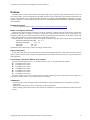
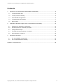
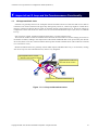
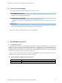
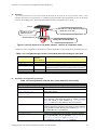
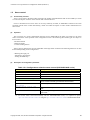
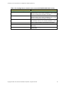
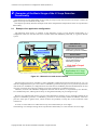
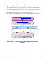
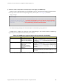
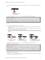
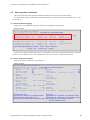
1
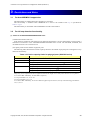
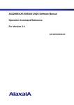
AX Series
L2 Loop Detection
Configuration Guide
Edition 2
Copyright © 2008, 2010, ALAXALA Networks Corporation. All rights reserved.
AX Series L2 Loop Detection Configuration Guide (Edition 2)
Preface
The AX Series L2 Loop Control Guide is intended to help system engineers grasp the operational overview of
each functionality, system configuration, and stable operation by providing them with technical information for
system configurations using each functionality related to L2 looping (Auto MDI/MDI-X suppression, L2 loop
detection, and storm control) supported by the AX series (AX6700S/AX6600S/AX6300S, AX3600S, AX2400S,
and AX1200S).
Related documents
x AX series product manuals (http://www.alaxala.com/en/techinfo/manual/index.html)
Notes on using this document
Information in this document is based on the basic operations verified under the environment specified by
ALAXALA Networks Corporation, and does not guarantee the operation of functionality, performance, and
reliability under all environment requirements. Please understand that this document is intended to help with
system configurations for ALAXALA Networks Corporation products.
The OS software versions are as follows at the point of creation of this document, unless otherwise specified:
AX6700S/AX6600S/AX6300S Ver. 11.3
AX3600S, AX2400S
Ver. 11.2
AX1230S
Ver. 1.4.F
AX1240S
Ver. 2.2
Information in this document is subject to change without notice.
Export restrictions
If you export this guide, you must check and comply with all applicable laws, rules and restrictions of Japan
and any other countries, such as Japan's Foreign Exchange and Foreign Trade Law and U.S. export control laws
and regulations.
Conventions: The terms "Switch" and "switch"
The term Switch (upper-case "S") is an abbreviation for any or all of the following models:
z AX6700S series switch
z AX6600S series switch
z AX6300S series switch
z AX3600S series switch
z AX2400S series switch
z AX1240S series switch
z AX1230S series switch
The term switch (lower-case "s") might refer to a Switch, another type of switch from the current vendor, or a
switch from another vendor. The context decides the meaning.
Trademarks
- The ALAXALA name and logo mark are trademarks or registered trademarks of ALAXALA Networks
Corporation.
- Ethernet is a trade name of Xerox Corporation in the United States.
- Other company and product names in this manual are trademarks or registered trademarks of their respective
owners.
Copyright © 2008, 2010, ALAXALA Networks Corporation. All rights reserved.
2
AX Series L2 Loop Detection Configuration Guide (Edition 2)
Revision history
Edition
Rev.
Date
Description
Edition 1
Edition 2
---
July 17, 2008
Feb. 17, 2010
First edition
Preface
The version of the used device has been updated.
Introduction to and usage example of the L2 loop
monitoring tool have been added.
Notes on using the AX6600S series have been added.
Appendix Configuration File has been updated.
Copyright © 2008, 2010, ALAXALA Networks Corporation. All rights reserved.
Applicable
sections
--2.1
2.2
2.3
4
3.2
Appendix
3
AX Series L2 Loop Detection Configuration Guide (Edition 2)
Contents
1.
2.
3.
Impact of an L2 Loop and the Countermeasure Functionality...........................................................5
1.1
L2 loops and their risks ...............................................................................................................5
1.2
L2 loop control functionality.........................................................................................................6
1.3
Auto MDI/MDI-X suppression......................................................................................................6
1.4
L2 loop detection functionality .....................................................................................................7
1.5
Storm control .............................................................................................................................10
Examples of the Basic Usage of the L2 Loop Detection Functionality ............................................12
2.1
Example of an application configuration ...................................................................................12
2.2
Important points for constructing a system ...............................................................................14
2.3
Configuration example ..............................................................................................................16
2.4
Troubleshooting with operation commands ..............................................................................18
2.5
Other operation commands.......................................................................................................23
Restrictions and Notes.....................................................................................................................24
3.1
For Auto MDI/MDI-X suppression .............................................................................................24
3.2
For L2 loop detection functionality ............................................................................................24
Appendix: Configuration File ....................................................................................................................26
Copyright © 2008, 2010, ALAXALA Networks Corporation. All rights reserved.
4
AX Series L2 Loop Detection Configuration Guide (Edition 2)
1. Impact of an L2 Loop and the Countermeasure Functionality
1.1
L2 loops and their risks
Networks are generally based on an assumption that the terminals and servers that send and receive data are
connected on an end-to-end basis both physically and logically. However, a data loop might be created due to
incorrect connections between devices used for network relaying (network devices) or incorrectly setting up
configurations on the network devices. If this occurs on a network controlled at the Layer 2 (L2) level, it is called an
L2 loop.
If an L2 loop is created, and then a broadcast frame enters, a serious problem occurs.
This causes an endless transfer of broadcast frames between the network devices and accordingly an increase in
the number of frames, leading to the compression of the transfer bandwidth that can be processed by the network
device and, in the worst case, results in a failure that stops other normal communication. (This condition is referred
to as a broadcast storm.)
Because broadcast frames are generally used for ARP requests and DHCP discovery in L2 networks, creating
such an L2 loop can cause a broadcast storm, which is very dangerous.
[3] Congestion due to a storm
-> Normal communication stopped
[2] Broadcasts continue to
flow and cause a storm!
[1] Incorrect connections cause a loop.
Figure 1.1-1 L2 loop and broadcast storm
Copyright © 2008, 2010, ALAXALA Networks Corporation. All rights reserved.
5
AX Series L2 Loop Detection Configuration Guide (Edition 2)
1.2
L2 loop control functionality
The AX series has the following functionality for preventing L2 loops:
Auto MDI/MDI-X suppression
Prevents L2 loops by creating no link-ups even with incorrect connections between access ports. This is
applicable only to twisted pair straight cables.
L2 loop detection functionality
Prevents L2 loops by detecting L2 loops in a device and blocking the port.
In addition to loops that close within the device, the detection of loops via upstream networks is also
possible.
Storm control
Restricts the receiver bandwidth of frames to a certain value when a storm occurs due to an L2 loop or
other cause, so that the impact on other communication can be minimized.
The following subsections describe the details of each functionality.
1.3
(1)
Auto MDI/MDI-X suppression
Functionality overview
Auto MDI/MDI-X refers to a functionality that automatically switches the MDI/MDI-X of a port in order to
eliminate any issues resulting from the different combinations of sending/receiving types (MDI/MDI-X) and
twisted pair cable types (straight/crossover) used for lines when a 1000BASE-T port interface is used. The Auto
MDI/MDI-X suppression functionality is used to suppress Auto MDI/MDI-X functionality, and uses only MDI-X
in order to prevent loops caused by twisted-pair straight cables.
Using a crossover cable causes a loop even if the Auto MDI/MDI-X suppression functionality is used. If a
1000BASE-X port interface is used, this functionality is disabled.
(2)
Description of the configuration and the parameter
Parameter
Description
Configured in interface configuration mode (config-if)
Disables the port's automatic MDIX functionality so that MDI-X is always used.
no mdix auto
Copyright © 2008, 2010, ALAXALA Networks Corporation. All rights reserved.
6
AX Series L2 Loop Detection Configuration Guide (Edition 2)
1.4
(1)
L2 loop detection functionality
Functionality overview
The L2 loop detection functionality is used to detect a loop failure in a Layer 2 network and correct the loop
failure by blocking the port that caused the loop. The L2 loop detection functionality can be used not only for core
networks made redundant with an L2 redundancy protocol, such as the spanning tree protocol and Ring Protocol,
but can also be used for access networks that cannot use such redundancy protocols.
Core network
Preventing loop failures via spanning trees, etc.
Switch A
Switch B
Pattern 1
An invalid connection on this
device causes a loop failure.
Switch C
Switch D
Switch E
Pattern 4
An invalid connection on a
device under the Switch
causes a loop failure across
the core network.
The L2 loop detection functionality can
prevent loop failures.
Access network
(Legend) ----: Improperly connected
line
: Loop flow
: Blocked status
Patterns 2 and 3
An invalid connection on the Switch
or an L2 switch under the device
causes a loop failure.
Figure 1.4-1 Basic patterns of loop failures
The L2 loop detection functionality can prevent the above-mentioned patterns (1 to 4) of loop failures.
Copyright © 2008, 2010, ALAXALA Networks Corporation. All rights reserved.
7
AX Series L2 Loop Detection Configuration Guide (Edition 2)
(2)
Operation
In L2 loop detection, an L2 control frame for detecting an L2 loop (an L2 loop detection frame) is sent
regularly from the port (a physical port or a channel group) specified in the configuration section. If the frame
returns to the sending device, the functionality determines that a loop failure has occurred.
Switch
Receipt of L2 loop detection frame
-> Detection of L2 loop
Sending L2 loop
detection frame
Small-scale hub, etc.
Incorrect connection
Figure 1.4-2 Loop failure on a hub under a device - the flow of a detection frame
Behaviors after a loop failure is detected are as follows depending on the configuration specified for the port.
Table 1.4-1 Configuration types of the L2 loop detection functionality for each port
Configuring ports
L2 loop
detection
frame sending
Yes
Yes
No
Behavior at receipt of an L2 loop detection frame
Detects L2 loops (log display) and blocks ports.
Only detects L2 loops (log display).
Detects L2 loops (log display) only for the applicable port.
Behavior according to the source settings at the source port#1
trap-port
No
Only detects L2 loops (log display).
exception-port
No
None
#1: For example, if send-inact-port is set to the source port, the source port is blocked.
send-inact-port
send-port
uplink-port
(3)
Description of configuration parameters
Table 1.4-2 Configurations related to the L2 loop detection functionality
Parameter
Description
Configured in global configuration mode (config)
loop-detection enable
Enables the L2 loop detection functionality of the device.
loop-detection
Releases (act) a blocked (inact) port automatically after a
auto-restore-time
certain period of time.
loop-detection
Sets the sending interval of L2 loop detection frames.
interval-time
loop-detection threshold
Sets the number of L2 loop detection frames receivable until the
port is blocked. If the threshold number of frames is received
during the period of time specified by loop-detection
hold-time after an L2 loop detection, the port is blocked.
loop-detection hold-time
Sets the retention time for the number of L2 loop detection frames
received until the port is blocked. The number of L2 loop detection
frames received is reset after the time specified by hold-time
has passed after an L2 loop detection.
Configured in interface configuration mode (config-if)
loop-detection
Sets the L2 loop detection frame sending or receiving behavior.
Any of the following can be specified: send-inact-port,
send-port, uplink-port, and exception-port
If this parameter is not set, trap-port is applied.
Copyright © 2008, 2010, ALAXALA Networks Corporation. All rights reserved.
8
AX Series L2 Loop Detection Configuration Guide (Edition 2)
(4)
Transmission rate and sending interval of L2 loop detection frames
The L2 loop detection functionality works when the target device sends and receives an L2 loop detection frame.
However, the transmission rate of L2 loop detection frames required for each device is determined based on the
sending interval of L2 loop detection frames and the number of VLAN ports subject to L2 loop detection. The
number of VLAN ports subject to L2 loop detection is the sum of the products of the number of physical interfaces
subject to L2 loop detection in the L2 loop detection functionality and the number of the VLANs used for the
respective interface.
(A) L2 loop detection frame rate per device (pps) =
Number of VLAN ports subject to L2 loop detection/sending interval of L2 loop detection frame (sec.)
(B) On the other hand, the L2 loop detection frame sending capacity depends on each device. (See the following
table.)
Table 1.4-3 L2 loop detection frame transmission rate
Model
Frame transmission rates (per device)#1
When using STP, GSRP, or the When not using STP, GSRP, or
Ring Protocol
the Ring Protocol
All models of the AX6700S/AX6300S series
All models of the AX3600S/AX2400S series
90 pps (recommended)#2
#2
30 pps (recommended)
600 pps (maximum)
#3
200 pps (maximum)#3
All models of the AX1200S series
20 pps (maximum)#3
#1: The transmission rate is automatically adjusted within the maximum value for each device (AX6700S/6300S series: 600
pps; AX3600S/AX2400S series: 200 pps; AX1200S series: 20 pps) according to the above-mentioned equation.
#2: When using STP, GSRP, or the Ring Protocol, set the transmission rate to the recommended value or less. If the
transmission rate is any higher, normal operation of STP, GSRP, or the Ring Protocol is not guaranteed.
#3: Frames that exceed the maximum value will not be sent. Loop failures cannot be detected on target ports or VLANs from
which frames have not been sent. Make sure that you set the transmission interval to achieve a transmission rate of no more
than the maximum value.
Accordingly, parameter (A) (the number of physical interfaces to be used, the number of VLANs, and the
sending interval) must be set so that (A) is less than or equal to (B). But it must eventually be adjusted using the
sending interval of L2 loop detection frames if the required device and the number of its physical interfaces and the
number of VLANs are determined by the network configuration or other factors.
This can be calculated by transforming the above-mentioned equation as follows:
Sending interval of L2 loop detection frame (sec.) ≥
Number of VLAN ports subject to L2 loop detection/frame transmission rate per device (pps)
As the time required for L2 loop detection is determined depending on this sending interval of the L2 loop
detection frame, it is preferred to set a value as small as possible within the range that satisfies the above inequality.
Example:
If one trunk port containing 19 access ports (with a VLAN) and 3 VLANs are used as the target of L2 loop
detection on an AX2400S series switch that uses STP:
For the sending interval of an L2 loop detection frame:
(19 x 1 + 1 x 3) / 30 (from Table 1.4-2) = 22 / 30 = 0.7333...
Based on this calculation, ALAXALA Networks Corporation recommends that you set a value of 1 (sec.).
Copyright © 2008, 2010, ALAXALA Networks Corporation. All rights reserved.
9
AX Series L2 Loop Detection Configuration Guide (Edition 2)
1.5
(1)
Storm control
Functionality overview
Storm control refers to the functionality that limits the number of flooded frames that are forwarded by a switch
to control the impact of storms on the network and connected devices.
Even if a broadcast storm occurs due to an L2 loop created by accident, its bandwidth is limited to the value
specified with the storm control functionality, which can reduce the impact on other normal communication to
some extent.
(2)
Operation
The occurrence of a storm is determined when the receiver bandwidth of the frame type subject to the storm
control exceeds the value specified in the configuration section. The following three frame types are subject to
storm control:
- Broadcast frames
- Multicast frames
- Unicast flooding frames
After a storm is detected, the receiver bandwidth of the target frame is limited. The following behaviors can also
be selected depending on the configuration:
- Blocking the target port
- Outputting a log message
- Issuing an SNMP trap
(3)
Description of configuration parameter
Table 1.5-1 Configurations related to storm control (AX6700S/6300S series)
Parameter
Description
Configured in global configuration mode (config)
storm-control broadcast
Enables storm control for broadcast frames.
storm-control multicast
Enables storm control for multicast frames.
storm-control unicast
Enables storm control for flooded unicast frames.
Configured in interface configuration mode (config-if)
storm-control level
Sets the threshold value for the receiver bandwidth for storm
control. Frames exceeding the threshold are discarded.
storm-control action
Blocks the port when a storm is detected.
inactivate
storm-control action trap
Issues an SNMP trap when a storm is detected and when a storm
ends.
storm-control action log
Outputs a log message when a storm is detected and when a
storm ends.
#1: To use the storm control functionality with the AX6700S/6300S series, it is required to specify
upc-in-and-storm-control using the upc-storm-control mode command beforehand.
Copyright © 2008, 2010, ALAXALA Networks Corporation. All rights reserved.
10
AX Series L2 Loop Detection Configuration Guide (Edition 2)
Table 1.5-2 Configurations related to storm control (AX3600S/2400S/1200S series)
Parameter
Description
Configured in interface configuration mode (config-if)
storm-control broadcast level pps Enables storm control for broadcast frames and sets the
threshold value for the receiver bandwidth for storm control.
Frames exceeding the threshold are discarded.
storm-control multicast level pps Enables storm control for multicast frames and sets the
threshold value for the receiver bandwidth for storm control.
Frames exceeding the threshold are discarded.
storm-control unicast level pps
Enables storm control for flooded unicast frames and sets
the threshold value for the receiver bandwidth for storm
control. Frames exceeding the threshold are discarded.
storm-control action inactivate
Blocks the port when a storm is detected.
storm-control action trap
Issues an SNMP trap when a storm is detected and when a
storm ends.
storm-control action log
Outputs a log message when a storm is detected and when
a storm ends.
Copyright © 2008, 2010, ALAXALA Networks Corporation. All rights reserved.
11
AX Series L2 Loop Detection Configuration Guide (Edition 2)
2. Examples of the Basic Usage of the L2 Loop Detection
Functionality
The efficient use of each functionality for preventing L2 loops can stop the occurrence of L2 loops or reduce the
impact of L2 loops to a minimum, if they occur.
This chapter specifically describes examples of the basic configurations and operations of the L2 loop detection
functionality.
2.1
Example of an application configuration
The following figure shows an example of the application of the L2 loop detection functionality in a
configuration with core switches and access switches connected redundantly with STP, as a general network
system.
Core network
Device E1
Core switch or
distribution switch
- Unseen from general users
- Redundancy protocol is enabled.
Redundant
configuration with STP
Access switch
Small-sca
le hub
No redundancy control
≈ Vulnerable to loops
- Accessible by general users
- Out of control range of
redundancy protocols
↓
High risk of loops!
To prevent this ↓
Application of L2 loop
detection functionality
Access network
Figure 2.1-1 General core and access network
STP and other protocols are available to control redundant configurations between network devices on a core
network configured at the Layer 2 level. Such L2 redundancy protocols also play a role to prevent loops between
network devices. In addition, as configurations of such networks are modified by the network administrator in most
cases, the occurrence rate of incorrect settings or incorrect connections is considered to be low.
Therefore, networks with redundant configuration between network devices, as represented by core networks,
are considered loop-free, reducing the necessity of using the functionality for preventing L2 loops.
However, for endpoints that connect to access switch destinations, terminals, servers, and hubs, and that do not
support L2 redundancy protocols, L2 redundancy protocols are not necessarily enabled. In addition, connection
ports are often open to general users, which increases the possibility of loops due to the invalid line cable
connections.
As such, it is most effective to enable the L2 loop control functionality at access edges.
The following is an example of using the L2 loop detection functionality on a switch used as an access edge.
Copyright © 2008, 2010, ALAXALA Networks Corporation. All rights reserved.
12
AX Series L2 Loop Detection Configuration Guide (Edition 2)
The following figure shows an example of a node of an access switch where the L2 loop detection functionality
is set.
(Option)
Upstream network of
STP (Rapid PVST+)
SNMP manager
IP address of Switch
192.168.10.1
(VLAN 10)
0/1
0/2
VLANs
E1: AX2430S-24T
VLAN 10
0/5
0/6
AX-NU (L2 loop
monitoring tool)
192.168.100.100
Empty (not
to be added)
192.168.100.200 public
VLAN 11
0/7
0/8
0/9
VLAN 12
...
0/3
0/4
0/23
10-12
0/24
L2 loop detection
uplink setting
L2 loop detection
and blocking setting
Empty (to be added)
Figure 2.1-2 Example of an access switch configuration
Ports 0/1 and 0/2 and Rapid PVST+ are used for connection with the upstream network.
For the endpoint side, where terminals and hubs are connected, ports 0/5 to 0/24 are used. Among those ports,
ports 0/5 and 0/6 are used by VLAN 10, ports 0/7 and 0/8 are by VLAN 11, and ports 0/9 to 0/23 are by VLAN 12.
Ports 0/9 to 0/23 are currently not connected to any devices, but might be connected to devices such as terminals or
hubs temporarily or in the future. Port 0/24 is used as a trunk port of VLANs 10 to 12.
Ports 0/3 and 0/4 are currently empty and no devices are to be connected in the meantime.
The status of this network system is monitored with SNMP, and L2 loop detection is also reported to the SNMP
manager.
Important points on constructing a system and configuration examples for the above-mentioned usage are shown
below.
Copyright © 2008, 2010, ALAXALA Networks Corporation. All rights reserved.
13
AX Series L2 Loop Detection Configuration Guide (Edition 2)
2.2
Important points for constructing a system
(1) Set the L2 loop detection functionality on a device located as near as possible to the endpoint, such as an access switch.
As described above:
- L2 redundancy protocols are used as measures against loops on upstream networks such as core networks in
many cases.
- When a port is blocked due to loop detection, devices located further upstream have more impact on
downstream networks.
For these reasons, ALAXALA Networks Corporation recommends that you use the L2 loop detection for a
device as near as possible to the endpoint.
(2) Set uplink-port for ports on the upstream network where L2 redundancy protocols are available.
Setting uplink-port blocks no ports when a control frame for L2 loop detection is sent or when a loop is
detected but receives and detects L2 loop detection frames.
This has no impact on L2 redundancy protocol operations on the upstream network and is effective for the
detection of loops created across devices via the upstream network.
(3) Enable the detection and port block setting (send-inact-port) for ports connected to endpoints such
as terminals and hubs.
Detection of a loop blocks ports, which can prevent loops. This can prevent broadcast storms caused by loops.
(4)
As a general rule, specify the L2 loop detection and port blocking setting for empty ports that might be connected to terminals
and hubs.
In particular, if devices are installed in locations easily accessed by general users, it is preferred that you specify
the setting in advance to prevent loops due to incorrect connections.
However, note that even ports in the link-down status are subject to L2 loop detection with this setting, affecting
the sending interval settings of L2 loop detection frames. (For details about the sending interval of L2 loop
detection frames, see 1.4 (4) Transmission rate and sending interval of L2 loop detection frames in this document
or 3. Switch capacities in the Software Manual Configuration Guide Vol. 1 for each device.)
Therefore, for devices installed in locations not easily accessed by general users, such as data centers, server
rooms, and inside racks, the use of the L2 loop detection functionality should be kept at a minimum level.
(5) Set shutdown for ports not to be used or prohibited.
For reasons similar to the above, if there is a port that is not to be connected or for which connection is prohibited
on a device installed in a location easily accessed by general users, disable (shutdown) the port in the
configuration in advance.
This setting allows for no loops to occur even if the port is improperly connected, because the port will not link
up.
Copyright © 2008, 2010, ALAXALA Networks Corporation. All rights reserved.
14
AX Series L2 Loop Detection Configuration Guide (Edition 2)
(6) When using STP, enable PortFast and the BPDU filter for access ports for which the L2 loop detection setting is enabled.
When STP is used for the L2 redundancy protocol, the functionality related to ports on the endpoint side include
PortFast, BPDU guard, and the BPDU filter. If the functionality is used with the L2 loop detection functionality,
ALAXALA Networks Corporation recommends that PortFast and the BPDU filter be enabled.
Enabling PortFast and the BPDU filter disables STP operations on the port, which can prevent interference
between STP and the L2 loop detection functionality.
(7) Set the sending interval of L2 loop detection frames to as small a value as possible.
The period of time from occurrence to detection of an L2 loop is determined by the sending interval of L2 loop
detection frames. So it is preferred to set a value as small as possible, according to the descriptions in 1.4 (4)
Transmission rate and sending interval of L2 loop detection frames in this document. As mentioned in the
descriptions, the sending interval of L2 loop detection frames can be calculated as follows:
<sending-interval-(sec.)> ≥ <number-of-VLAN-ports-subject-to-L2-loop-detection> / <frame-transmission-rate-(pps)>
If calculated taking the above-mentioned configuration as an example,
<sending-interval-(sec.)> ≥ (2 x 1 + 2 x 1 + 15 x 1 + 1 x 3) / 30 = 0.73
0/5-6, 0/7-8, 0/9-23: 1 VLAN for each, 0/24: 3 VLANs
Recommended value for using STP on
AX2430S (pps)
From this result, set the L2 loop detection frame sending interval to 1 (sec.) for the above-mentioned configuration.
Copyright © 2008, 2010, ALAXALA Networks Corporation. All rights reserved.
15
AX Series L2 Loop Detection Configuration Guide (Edition 2)
2.3
Configuration example
The following table provides configuration examples of important points for constructing a system. For details
about overall configuration, see the Appendix.
(1) Configuring an access edge node
Configuring E1
Configuring STP
(config)# spanning-tree mode rapid-pvst
(config)# spanning-tree portfast default
Use Rapid PVST+ for the connection with the
upstream network.
The PortFast functionality is used by default.
(Important points for constructing a system (6))
Configuring control VLANs and data transfer VLANs
(config)# vlan 10-12
Configure VLANs 10-12 to be used.
Configuring the L2 loop detection functionality
(config)# loop-detection enable
(config)# loop-detection interval-time 1
Enable the L2 loop detection functionality.
(Important points for constructing a system (1))
Set the control frame sending interval of the L2 loop
detection functionality to one second.
(Important points for constructing a system (7))
Configuring ports
Configuring uplink ports
(config)# interface range gigabitethernet 0/1-2
(config-if)# link debounce time 0
(config-if)# switchport mode trunk
(config-if)# switchport trunk allowed vlan 10-12
(config-if)# spanning-tree portfast disable
(config-if)# loop-detection uplink-port
Set link debounce time to 0.
Configure VLANs 10-11 to be used.
Cancel the PortFast setting so that the port is used as
the target of STP.
Set the port as an uplink port for L2 loop detection.
(Important points for constructing a system (2))
Configuring unused ports (not to be used in the future)
(config)# interface range gigabitethernet 0/3-4
(config-if)# shutdown
Shut down the ports that are not to be used.
(Important points for constructing a system (5))
Configuring access ports
(config)# interface range gigabitethernet 0/5-6
(config-if)# switchport mode access
(config-if)# switchport access vlan 10
(config-if)# spanning-tree bpdufilter enable
(config-if)# loop-detection send-inact-port
(config)# interface range gigabitethernet 0/7-8
(config-if)# switchport mode access
(config-if)# switchport access vlan 11
(config-if)# spanning-tree bpdufilter enable
(config-if)# loop-detection send-inact-port
(config)# interface range gigabitethernet 0/9-23
(config-if)# switchport mode access
(config-if)# switchport access vlan 12
(config-if)# spanning-tree bpdufilter enable
(config-if)# loop-detection send-inact-port
(config)# interface gigabitethernet 0/24
(config-if)# switchport mode trunk
(config-if)# switchport trunk allowed vlan 10-12
(config-if)# spanning-tree bpdufilter enable
(config-if)# loop-detection send-inact-port
Configure ports 0/5-6.
Configure VLAN 10 to be used as an access port.
Enable the BPDU filter functionality of STP.
(Important points for constructing a system (6))
Set the port as a detecting and blocking port for L2
loop detection.
(Important points for
constructing a system (3))
Configure ports 0/7-8.
Configure VLAN 11 to be used as an access port.
Enable the BPDU filter functionality of STP.
(Important points for constructing a system (6))
Set the port as a detecting and blocking port for L2
loop detection.
(Important points for
constructing a system (3))
Configure ports 0/9-23.
Configure VLAN 12 to be used as an access port.
Enable the BPDU filter functionality of STP.
(Important points for constructing a system (6))
Set the port as a detecting and blocking port for L2
loop detection.
(Important points for
constructing a system (4))
5
Configure port 0/24.
Configure VLANs 10-12 to be used as a trunk port.
Enable the BPDU filter functionality of STP.
(Important points for constructing a system (6))
Set the port as a detecting and blocking port for L2
loop detection.
(Important points for
constructing a system (4))
5
Copyright © 2008, 2010, ALAXALA Networks Corporation. All rights reserved.
16
AX Series L2 Loop Detection Configuration Guide (Edition 2)
Configuring E1
Configuring an SNMP trap destination
(config)# snmp-server host 192.168.100.200 traps
"public" loop-detection
Set the host address and community name of the
SNMP manager to which traps related to the L2 loop
detection functionality are issued.
Configuring a device IP
(config)# interface vlan 10
(config-if)# ip 192.168.10.1 255.255.255.0
Set an IP address to one of the VLANs connected to
uplink ports in order to issue traps related to the L2
loop detection functionality.
Configuring a default gateway
(config)# ip default-gateway 192.168.10.254
Set the default gateway to enable communication
externally.
Copyright © 2008, 2010, ALAXALA Networks Corporation. All rights reserved.
17
AX Series L2 Loop Detection Configuration Guide (Edition 2)
2.4
Troubleshooting with operation commands
This section describes the basic operations of the L2 loop detection functionality in the configuration example.
When the L2 loop detection functionality detects an L2 loop, the detection of a loop is output in the message log
of the device and a log entry is recorded. It is also possible to issue an SNMP trap.
When an L2 loop is detected in a device, the loop status and other information can be viewed for each device
using the operation commands related to the L2 loop detection functionality as shown below.
After that, investigate the location of the loop by referring to this information as well as the network
configuration diagram and the actual wiring status.
L2 loop occurs! (0H(1) Detecting the L2 loop status)
- Message log
- SNMP trap
1H(2) Identifying the loop location
- show logging (Shows the log message)
- show loop-detection (Shows the loop status)
Determining the cause of the loop (incorrect connection or incorrect setting)
If the cause is an incorrect
connection
Disconnect the cable.
If the cause is an incorrect setting
Check the configuration and layout.
Correct the configuration,
etc.
2H(3) Restoring blocked ports and removing the loop status
display
- show port (Shows the port status)
activate (Releases the blocked port)
- show loop-detection (Shows the loop status)
show loop detection Clears the Down(loop) status#1
#1: When the port is set to be blocked at the detection of an L2 loop (send-inact-port)
and has no link destination after the loop status is removed
Figure 2.4-1 Operation (troubleshooting) procedure related to the L2 loop detection
functionality
Copyright © 2008, 2010, ALAXALA Networks Corporation. All rights reserved.
18
AX Series L2 Loop Detection Configuration Guide (Edition 2)
(1) Detection of the L2 loop status via message logs, show logging, and SNMP traps
When an L2 loop is detected and the port is blocked due to this loop, message logs are displayed as shown below.
These logs can be viewed also in the log message history shown by the show logging command.
Display example
E1>sh logging
...
EVT 06/26 17:19:57 E4 VLAN 20800001 0700:000000000000 L2LD : Port(0/24): inactivated because of
loop detection from port(0/24). --- Port 0/24 is deactivated due to L2 loop detection sent from port 0/24.
EVT 06/26 17:19:57 E4 VLAN 20800005 0700:000000000000 L2LD : Port(0/1): loop detection from
--- L2 loop with source port 0/24 is detected at port 0/1.
port(0/24).
...
For details about log messages, see the manual Software Manual Message Log Reference.
If SNMP traps are enabled, trap notification to the SNMP manager is also available. Details of SNMP traps
supported by the L2 loop detection functionality are as follows.
Table 2.4-1 SNMP traps supported by the L2 loop detection functionality
Type
axsL2ldLinkDown
Meaning
Transition of a line to the
communication disabled
state via L2 loop detection
axsL2ldLinkUp
Transition of a line to the
communication enabled
state via the
automatic-restoration
functionality of L2 loop
detection
L2 loop detection
axsL2ldLoopDetection
Issued when
This trap is issued when the operating state of an
interface is changed from ACTIVE (communication
enabled) to DISABLE (communication disabled) by L2
loop detection.
This trap is issued when the operating state of an
interface is changed from DISABLE (communication
disabled) to ACTIVE (communication enabled) by the
automatic-restoration functionality of L2 loop
detection.
This trap is issued when an L2 loop is detected.
This trap is issued every 60 seconds while the L2 loop
still exists.
For more details about MIB information, see the manual Software Manual MIB Reference for each device.
Copyright © 2008, 2010, ALAXALA Networks Corporation. All rights reserved.
19
AX Series L2 Loop Detection Configuration Guide (Edition 2)
(2) Identification of loop location with the show loop-detection command
The status of L2 loops can be checked mainly with the show loop-detection command.
Example of executing the show loop-detection command
E1> sh loop-detection
--- Date and time of command execution
-----Date
and time
of command
execution
L2 loop
detection
frame sending
interval
-----L2Output
loop detection
framerate
sending interval
:1
transmission
-----Output
transmission
rate
Number
of received
L2 loop detection frames determined to be
:30pps
---loop
Number
of L2 loop detection frames receivable until a loop is
detection
:1
detected
--Received L2 loop detection frame hold time
:infinity--- Received L2 loop detection frame hold time
--- Automatic-restoration time after being blocked
:--- Automatic-restoration time after being blocked
No. of VLAN ports subject to L2 loop detection
Date 2008/06/26 17:43:54 UTC
Interval Time
Output Rate
Threshold
Hold Time
Auto Restore Time
VLAN Port Counts
Configuration
:22
Capacity
:30
No. of VLAN ports available for L2 loop detection
Port Information
Port
Status
Type
0/1
Up
uplink
DetectCnt RestoringTimer
-
-
SourcePort
0/24
0/2
Up
uplink
-
-
-
0/3
Down
trap
0
-
-
0/4
Down
trap
0
-
-
0/5
Down
send-inact
0
-
-
0/6
Down(loop) send-inact
20
-
0/6
0/7
Down
send-inact
0
-
-
Port
No.
Port
status
Port
type
Vlan
12
10
Current
Time to automatic Source Source
detection count restoration
port
VLAN ID
The following examples show display results for each actual loop pattern:
(a) Loop caused by connecting two port on the same switch device:
- A loop is created by connecting two ports on the same switch device.
- A loop is created by connecting a port on a switch device and a port on an intermediate device (such as a hub)
connected to the switch device.
- A loop is created by connecting two intermediate devices (such as hubs) linked to the same switch device.
0/5
0/6
- Connecting ports on the
same switchdevice
0/5
0/5
0/6
- Connecting a hub under
the device to another port
on the device
0/6
- Connecting hubs under
the device
In these cases, using the show loop-detection command results in the following display:
>show loop-detection
...
Port Information
Port Status
Type
0/5
Down(loop) send-inact
...
0/6
Down(loop) send-inact
DetectCnt RestoringTimer SourcePort
1
- 0/6
1
-
0/5
Vlan
10
10
This indicates that port 0/5 is in the inact status because port 0/5 received an L2 loop detection frame from port
0/6 and that port 0/6 is in the inact status because port 0/6 received an L2 loop detection frame from port 0/5.
(b) Loop in the same port on the same switch device:
Copyright © 2008, 2010, ALAXALA Networks Corporation. All rights reserved.
20
AX Series L2 Loop Detection Configuration Guide (Edition 2)
A loop is created by connecting two ports on an intermediate device (such as a hub) belonging to the switch
device.
0/5
- Connecting ports on a hub
under the device
In this case, using the show loop-detection command results in the following display:
>show loop-detection
...
Port Information
Port Status
Type
0/5
Down(loop) send-inact
DetectCnt RestoringTimer SourcePort
1
- 0/5
Vlan
10
This indicates that port 0/5 is in the inact status because port 0/5 received an L2 loop detection frame from port
0/5 itself.
(c) Loop with another switch device (via upstream network):
- A loop is created by connecting a switch device to another switch device via an upstream network in the
same segment.
- A loop is created by connecting an intermediate device (such as a hub) under a switch device to another
switch device via an upstream network in the same segment.
- A loop is created by connecting an intermediate device (such as a hub) under a switch device to an
intermediate device (such as a hub) under another switch device via an upstream network in the same
segment.
0/1
0/5
- Connecting the device and
another device
0/1
0/1
0/5
0/5
- Connecting a hub under the
device and another device
- Connecting a hub under the device
and a hub under another device
In these cases, using the show loop-detection command results in the following display:
(When port 0/1 is set as an uplink port)
>show loop-detection
...
Port Information
Port Status
Type
0/1
Up
uplink
0/5
Down(loop) send-inact
DetectCnt RestoringTimer SourcePort
- 0/5
1
- 0/1(U)
Vlan
10
10
This indicates that port 0/5 as a source port is in the inact status because port 0/1 as an uplink port received an
L2 loop detection frame from port 0/5.
As shown above, you can investigate ports in the loop status based on the messages by the operation command
by referring to the network configuration diagram.
Copyright © 2008, 2010, ALAXALA Networks Corporation. All rights reserved.
21
AX Series L2 Loop Detection Configuration Guide (Edition 2)
(3) Restoring (activating) blocked ports and removing the loop status display
After taking measures against the L2 loop status, restore blocked ports and remove the loop status display.
Follow the procedures below.
(i) Restoring the blocked ports
Use the show port command to confirm that the blocked port is in the inact status and then activate the
port.#1
(ii) Checking the loop status display
Execute the show loop-detection command. After that, confirm whether either of the following is true:
(a) If the activated port has a link destination, confirm that the status display of the port becomes Up, indicating
a link-up.
(b) If the activated port has no link destination, it will not enter the link-up status. Even if the show
loop-detection command is executed, the Down(loop) status still remains on the port. To remove
this status display (to change the display to the Down status display), the following two methods are
available:#2
Method 1: To clear the status of a specific port only, temporarily remove the send-inact-port setting
for the port from the configuration. (Temporarily specify no loop-detection
send-inact-port and then specify loop-detection send-inact-port again.)
Method 2: To clear the status of the whole device, set the L2 loop detection functionality all over again
from the configuration. (Temporarily specify no loop-detection enable and then specify
loop-detection enable again.)
After removing the status via either of the above methods, execute the show loop-detection
command again to confirm that the port is in the Down status.
#1: It is also possible to set the configuration in advance so that the port is automatically activated after a certain period of time
has passed (loop-detection auto-restore-time). In this case, the port is automatically activated when a
specified period of time has passed after detection of an L2 loop. However, the activation operation occurs even while the
L2 loop exists. In this case, L2 loop status is detected again after activation.
#2: When the status of a specific port is removed, the statistics (for the port) displayed with show loop-detection
statistics remain. When the status of the whole device is removed, the statistics displayed with show
loop-detection statistics are all removed.
Copyright © 2008, 2010, ALAXALA Networks Corporation. All rights reserved.
22
AX Series L2 Loop Detection Configuration Guide (Edition 2)
2.5
Other operation commands
This section describes other operation commands related to the L2 loop detection functionality.
For details about operation commands, see the manual Software Manual Operation Command Reference Vol. 1
for each device.
(1) show loop-detection logging
Displays the L2 loop detection log entries with the L2 loop detection functionality.
Display example
E1> sh loop-detection logging
Date 2008/06/26 17:44:02 UTC --- Date and time of command execution
2008/06/26 17:19:57 0/1
Source: 0/24
Vlan: 12
Uplink
2008/06/26 17:19:57 0/1
Source: 0/24
Vlan: 11
Uplink
2008/06/26 17:19:57 0/1
Source: 0/24
Vlan: 10
Uplink Inactive
2008/06/26 17:18:32 0/1
Source: 0/24
Vlan: 12
Uplink
2008/06/26 17:18:32 0/1
Source: 0/24
Vlan: 11
Uplink
2008/06/26 17:18:32 0/1
Source: 0/24
Vlan: 10
Uplink Inactive
2008/06/26 17:08:04 0/23
Source: 0/24
Vlan: 10
[1]
Time L2loop detected Received Source Source Uplink Switched to
port No. port
VLAN ID port inactive
[1] above, for example, indicates that port 0/1 as an uplink port received L2 loop detection frames from port 0/23
VLANs 10-12 on 2008-06-26 at 17:19:57 and that the source port 0/23 was in the deactivated status.
(2) show loop-detection statistics
Displays the statistics related to L2 loop detection.
Display example
E1> sh loop-detection statistics
Date 2008/06/26 17:44:19 UTC --- Date and time of command execution
Port:0/1
Up --- [1]
Type :uplink --- [2]
TxFrame
: --- [3]
0 RxFrame
:
40
--- [5]
Inactive Count:
0 RxDiscard
:
0
--- [7]
Last Inactive :
- Last RxFrame : 2008/06/26 17:19:57
Port:0/2
Up
Type :uplink
TxFrame
:
0 RxFrame
:
0
Inactive Count:
0 RxDiscard
:
0
Last Inactive :
- Last RxFrame :
Port:0/5
Down
Type :send-inact
TxFrame
:
0 RxFrame
:
0
Inactive Count:
0 RxDiscard
:
0
Last Inactive :
- Last RxFrame :
Port:0/6
Down(loop) Type :send-inact
TxFrame
:
5538 RxFrame
:
258
Inactive Count:
15 RxDiscard
:
0
Last Inactive : 2008/06/26 14:39:05 Last RxFrame : 2008/06/26 14:39:05
:
[1] Port No. and status
[3] TxFrame: No. of sent L2 loop detection frames
[5] Inactive Count: Inactive status count
[7] Last Inactive: Date and time of last inactive status
--- [4]
--- [6]
--- [8]
[2] Port type
[4] RxFrame: No. of received L2 loop detection frames
[6] RxDiscard: No. of discarded L2 loop detection frames
[8] Last RxFrame: Date and time of receipt of
last L2 loop detection frame
Copyright © 2008, 2010, ALAXALA Networks Corporation. All rights reserved.
23
AX Series L2 Loop Detection Configuration Guide (Edition 2)
3. Restrictions and Notes
3.1
For Auto MDI/MDI-X suppression
This functionality is enabled when auto-negotiation is specified.
This functionality is disabled when 1000BASE-X is used as the interface and sfp is specified for
media-type.
This functionality is unavailable when 10GBASE-R is used as the interface.
3.2
For L2 loop detection functionality
(1) Notes for the AX67000S/AX6600S/AX6300S series
(a) Maximum number of devices
In the same L2 segment for which the L2 loop detection functionality is set, this functionality can be used for a
maximum of 64 devices in the AX6700S/AX6600S/AX6300S series in total. The AX3600S, AX2400S, and
AX1200S series have no such restrictions.
(b) Capacity limits for the number of physical ports
The following tables describe the Switch's capacity limits for the number of physical ports running the L2 loop
detection functionality.
Table 3.2-1 Device capacity limits for physical ports (AX6700S series)
NIF abbreviation
Number of available physical ports#1
NK1G-24T
All ports
NK1G-24S
All ports
NK10G-4RX
Up to two ports with one BSU
#2
All ports with two or more BSUs (double-act or higher)
NK10G-8RX
Up to two ports with one BSU
Up to four ports with two BSUs (double-act)#3
Up to six ports with three BSUs (triple-act)#4, #5
#1: If the number of physical ports exceeding the capacity limit is used and a high load of traffic flows continually or
temporarily, an L2 loop detection frame might be discarded. This might cause a delay in the detection of a loop failure.
#2: To ensure BSU redundancy, use three BSUs (triple-act).
#3: Use port numbers 1-4, 3-6, or 5-8.
#4: Use port numbers 1-6 or 3-8.
#5: To ensure BSU redundancy, use no more than four physical ports. However, use any of the following port numbers:
1-4, 3-6, or 5-8
Copyright © 2008, 2010, ALAXALA Networks Corporation. All rights reserved.
24
AX Series L2 Loop Detection Configuration Guide (Edition 2)
Table 3.2-2 Device capacity limits for physical ports (AX6600S series)
NIF abbreviation
NK1G-24T
Number of available physical ports#1
12 ports when in single active PSP mode
All ports when in double active PSP mode
NK1G-24S
12 ports when in single active PSP mode
All ports when in double active PSP mode
NK1GS-8M
All ports
NK10G-4RX
1 port when in single active PSP mode
2 ports when in double active PSP mode#2, #3
NK10G-8RX
1 port when in single active PSP mode
2 ports when in double active PSP mode#3, #4
#1: If the number of physical ports exceeding the capacity limit is used and a high load of traffic flows continually or
temporarily, an L2 loop detection frame might be discarded. This might cause a delay in detection of a loop failure.
#2: Use port numbers 1-2 or 3-4.
#3: To ensure CSU redundancy, use no more than one physical port.
#4: Use port numbers 1-2, 3-4, 5-6, or 7-8.
Table 3.2-3 Device capacity limits for physical ports (AX6300S series)
NIF abbreviation
Number of available physical ports#1
NH1G-16S
1 port per group of four ports starting from the top port, up to a maximum of 4 ports.
NH1G-24T
Up to 12 ports
NH1G-24S
Up to 12 ports
NH1G-48T
1 port per group of four ports starting from the top port, up to a maximum of 12 ports.
NH10G-1RX
All ports
NH10G-4RX
Only 1 port
NH10G-8RX
Only 1 port
#1: If the number of physical ports exceeding the capacity limit is used and a high load of traffic flows continually or
temporarily, an L2 loop detection frame might be discarded. This might cause a delay in detection of a loop failure.
(2) Status display of the show loop-detection command
The show loop-detection command updates the displayed contents when the port link status changes.
For example, for a port that has once changed to the Down(loop) status due to the detection of a loop, the
status display remains until the port links up again even if it is activated after the loop status is removed.
However, while the port is set to be automatically activated after a certain period of time using the
loop-detection auto-restore-time command, the Down status is displayed if the L2 loop status is
removed with no link destination before the specified period of time has passed after L2 loop detection.
Copyright © 2008, 2010, ALAXALA Networks Corporation. All rights reserved.
25
AX Series L2 Loop Detection Configuration Guide (Edition 2)
Appendix: Configuration File
This file shows examples of configurations described in this guide.
The text file attached to this file contains all of the configurations for each device in each network configuration
described in Chapter 2. (Extracting the attachment file requires Adobe Acrobat 5.0 or later or Adobe Reader 6.0 or
later.)
For details about each configuration, see the attachment with the same name as shown below.
2. Examples of Basic Usage of L2 Loop Detection Functionality
2.1. Example of access switch configuration
Access edge switch
Device name and applicable device
E1
Copyright © 2008, 2010, ALAXALA Networks Corporation. All rights reserved.
Applicable file
2-1_L2LD_E1.txt
26
Edition 2 – February 17, 2010
Network Technical Support
ALAXALA Networks Corporation
Shin-Kawasaki Mitsui Bldg West Tower, 890
Kashimada, Saiwai-ku, Kawasaki-shi,
Kanagawa 212-0058, JAPAN
3Hhttp://www.alaxala.com/en/index.html